Embed Size (px)
Citation preview

6635 Kitimat Road, Unit 34; Mississauga, Ontario; Canada L5N 6J2; Tel: (905) 858-7663 Fax: (905) 858-4419 Toll Free 1-800-265-3376
Web Site: www.graphicwhizard.com
GW 6000Reference
Manual
Shown with optional second head & optional stand
GRAPHIC WHIZARD6635 Kitimat Road, Unit 34
Mississauga, Ontario L5N 6J2
Phone # (905) 858-7663 Fax # (905) 858-4419
Toll Free: 1-800-265-3376
Web Site: www.graphicwhizard.com
Version 99-07

2
3
TABLE OF CONTENTS
1.0 General Operation 3
1.1 Technical Data 3
1.2 Safety Regulations 3
1.3 Cautions Concerning Machine 4
2.0 Machine Assembly 5
2.1 Feed and Exit Trays 5
2.2 Numbering Heads 6
2.3 Optional Conveyor Outfeed Plate 7
2.4 Additional Switches and Control 7
3.0 Operating Keyboard 8
3.1 Running a Job 8
3.2 Stopping a Job 8
3.3 Clearing a Program 9
3.4 Changing and Programming a Job 9
3.5 Speed Control 10
4.0 Setting Up a Job 10
4.1 Aligning the Feed Tray Guides 10
4.2 Setting Feed Tire Pressure 10
4.3 Perforating/Slitting 12
4.4 Scoring 13
4.5 Idler Wheel Holders 14
4.6 Main Rollers 14
4.7 Installing Ink Pads 14
4.8 Locating the Numbering Heads 15
4.9 Stripper Assemblies 15
4.10Setting Impression Control 15
4.11Flatness of Impression 16
4.12Exit Rollers 17
5.0 Running a Job 17
5.1 Setting the Start Number 17
5.2 Setting the Repeat Selector 17
5.3 Fanning 18
6.0 Maintenance 19
6.1 Numbering Heads 19
6.2 Machine Cleaning 19
6.3 Lubrication 20
6.4 Friction Feed 20
7.0 Troubleshooting 21
Friction Feeder 21
Print Quality 21
Registration 22
Numbering Heads 22
Error codes 24
Parts List 25
GW 6000 PARTS LIST 25
GW 6000 PARTS DIAGRAM 29
4
1.0 GENERAL OPERATION
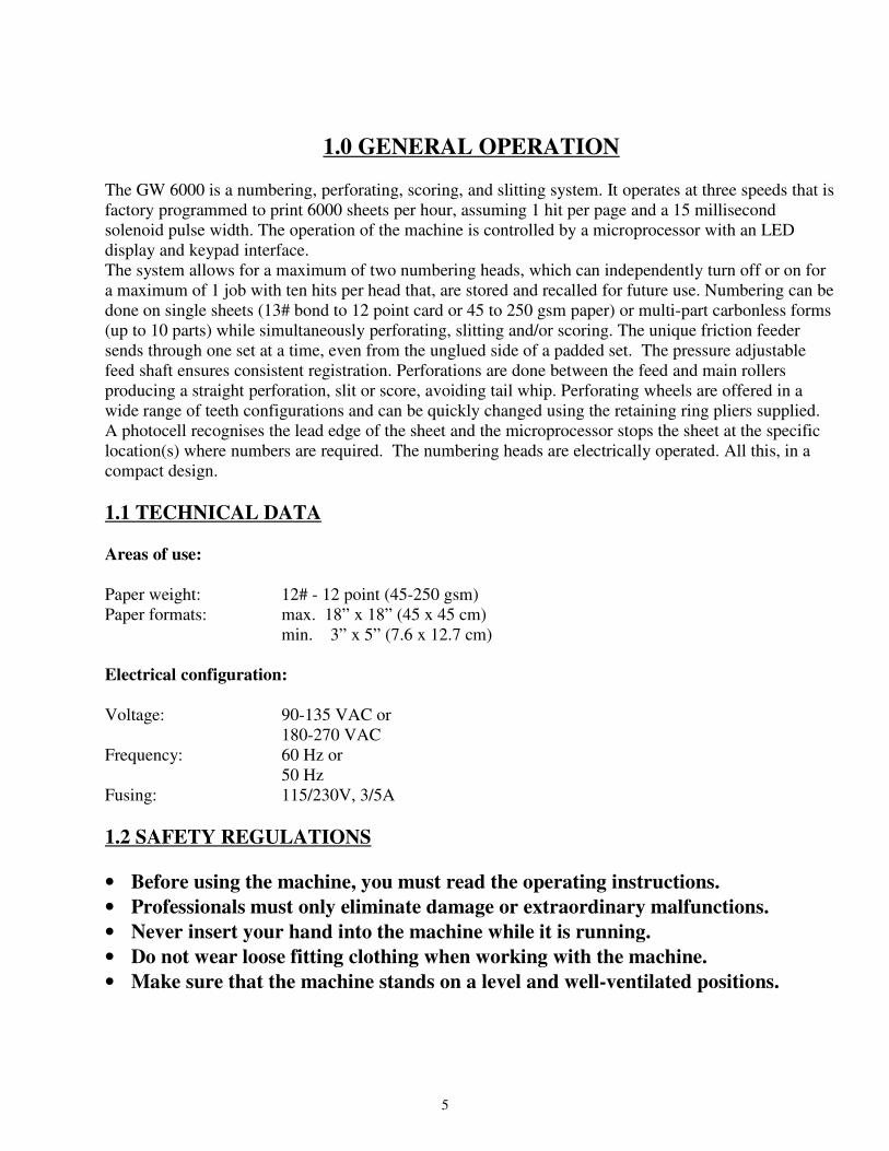
The GW 6000 is a numbering, perforating, scoring, and slitting system. It operates at three speeds that is
factory programmed to print 6000 sheets per hour, assuming 1 hit per page and a 15 millisecond
solenoid pulse width. The operation of the machine is controlled by a microprocessor with an LED
display and keypad interface.
The system allows for a maximum of two numbering heads, which can independently turn off or on for
a maximum of 1 job with ten hits per head that, are stored and recalled for future use. Numbering can be
done on single sheets (13# bond to 12 point card or 45 to 250 gsm paper) or multi-part carbonless forms
(up to 10 parts) while simultaneously perforating, slitting and/or scoring. The unique friction feeder
sends through one set at a time, even from the unglued side of a padded set. The pressure adjustable
feed shaft ensures consistent registration. Perforations are done between the feed and main rollers
producing a straight perforation, slit or score, avoiding tail whip. Perforating wheels are offered in a
wide range of teeth configurations and can be quickly changed using the retaining ring pliers supplied.
A photocell recognises the lead edge of the sheet and the microprocessor stops the sheet at the specific
location(s) where numbers are required. The numbering heads are electrically operated. All this, in a
compact design.
1.1 TECHNICAL DATA
Areas of use:
Paper weight: 12# - 12 point (45-250 gsm)
Paper formats: max. 18” x 18” (45 x 45 cm)
min. 3” x 5” (7.6 x 12.7 cm)
Electrical configuration:
Voltage: 90-135 VAC or
180-270 VAC
Frequency: 60 Hz or
50 Hz
Fusing: 115/230V, 3/5A
1.2 SAFETY REGULATIONS
• Before using the machine, you must read the operating instructions.
• Professionals must only eliminate damage or extraordinary malfunctions.
• Never insert your hand into the machine while it is running.
• Do not wear loose fitting clothing when working with the machine.
• Make sure that the machine stands on a level and well-ventilated positions.
5
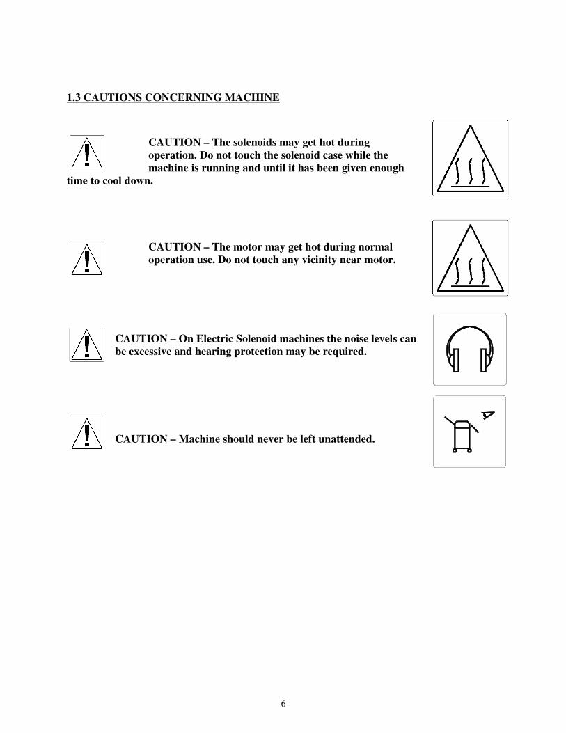
1.3 CAUTIONS CONCERNING MACHINE
CAUTION – The solenoids may get hot during
operation. Do not touch the solenoid case while the
machine is running and until it has been given enough
time to cool down.
CAUTION – The motor may get hot during normal
operation use. Do not touch any vicinity near motor.
CAUTION – On Electric Solenoid machines the noise levels can
be excessive and hearing protection may be required.
CAUTION – Machine should never be left unattended.
6
2.0 MACHINE ASSEMBLY
2.1 Feed and Exit Trays
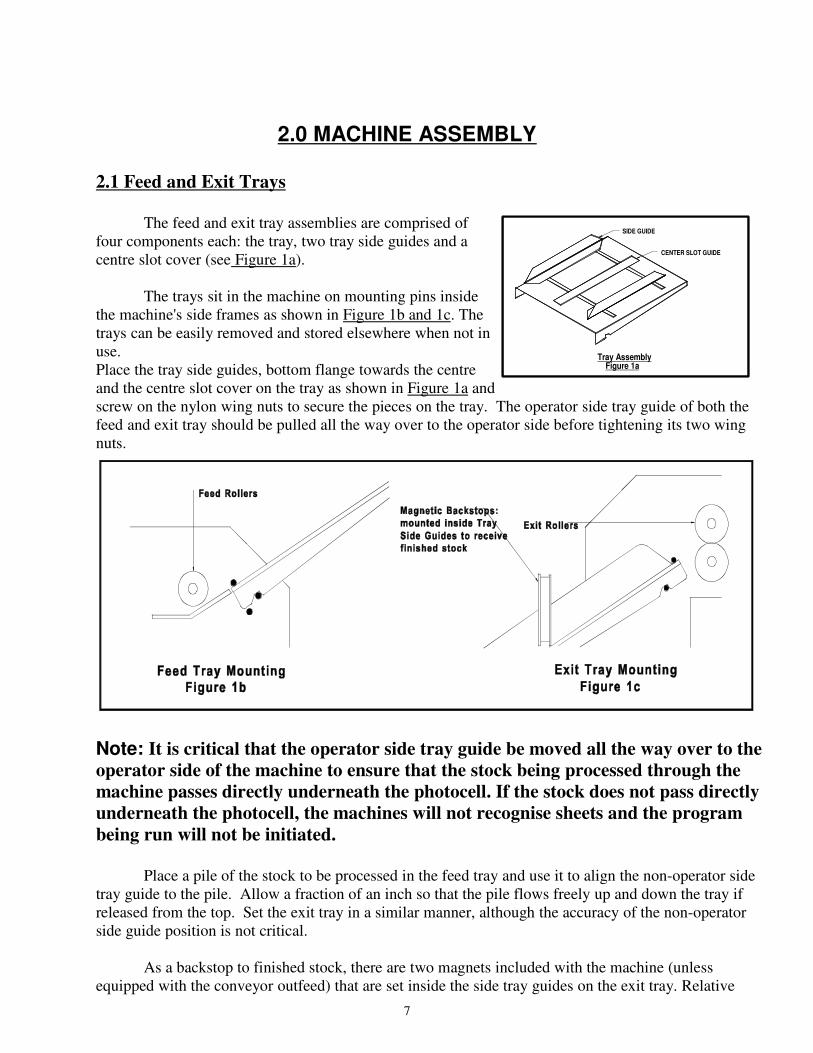
The feed and exit tray assemblies are comprised of
four components each: the tray, two tray side guides and a
centre slot cover (see Figure 1a).
The trays sit in the machine on mounting pins inside
the machine's side frames as shown in Figure 1b and 1c. The
trays can be easily removed and stored elsewhere when not in
use.
Place the tray side guides, bottom flange towards the centre
and the centre slot cover on the tray as shown in Figure 1a and
screw on the nylon wing nuts to secure the pieces on the tray. The operator side tray guide of both the
feed and exit tray should be pulled all the way over to the operator side before tightening its two wing
nuts.
Note: It is critical that the operator side tray guide be moved all the way over to the
operator side of the machine to ensure that the stock being processed through the
machine passes directly underneath the photocell. If the stock does not pass directly
underneath the photocell, the machines will not recognise sheets and the program
being run will not be initiated.
Place a pile of the stock to be processed in the feed tray and use it to align the non-operator side
tray guide to the pile. Allow a fraction of an inch so that the pile flows freely up and down the tray if
released from the top. Set the exit tray in a similar manner, although the accuracy of the non-operator
side guide position is not critical.
As a backstop to finished stock, there are two magnets included with the machine (unless
equipped with the conveyor outfeed) that are set inside the side tray guides on the exit tray. Relative
SIDE GUIDE
CENTER SLOT GUIDE
Tray AssemblyFigure 1a
7
position of the magnets depends on the stock being processed, but the magnets should be set such that
the stock does not slide down the exit tray too far, possibly causing sheets to get in uncollated order.
2.2 Numbering Heads
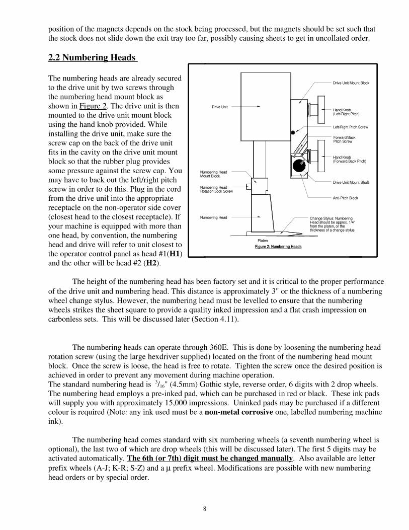
The numbering heads are already secured
to the drive unit by two screws through
the numbering head mount block as
shown in Figure 2. The drive unit is then
mounted to the drive unit mount block
using the hand knob provided. While
installing the drive unit, make sure the
screw cap on the back of the drive unit
fits in the cavity on the drive unit mount
block so that the rubber plug provides
some pressure against the screw cap. You
may have to back out the left/right pitch
screw in order to do this. Plug in the cord
from the drive unit into the appropriate
receptacle on the non-operator side cover
(closest head to the closest receptacle). If
your machine is equipped with more than
one head, by convention, the numbering
head and drive will refer to unit closest to
the operator control panel as head #1(H1)
and the other will be head #2 (H2).
The height of the numbering head has been factory set and it is critical to the proper performance
of the drive unit and numbering head. This distance is approximately 3" or the thickness of a numbering
wheel change stylus. However, the numbering head must be levelled to ensure that the numbering
wheels strikes the sheet square to provide a quality inked impression and a flat crash impression on
carbonless sets. This will be discussed later (Section 4.11).
The numbering heads can operate through 360Ε. This is done by loosening the numbering head
rotation screw (using the large hexdriver supplied) located on the front of the numbering head mount
block. Once the screw is loose, the head is free to rotate. Tighten the screw once the desired position is
achieved in order to prevent any movement during machine operation.
The standard numbering head is 3/16" (4.5mm) Gothic style, reverse order, 6 digits with 2 drop wheels.
The numbering head employs a pre-inked pad, which can be purchased in red or black. These ink pads
will supply you with approximately 15,000 impressions. Uninked pads may be purchased if a different
colour is required (Note: any ink used must be a non-metal corrosive one, labelled numbering machine
ink).
The numbering head comes standard with six numbering wheels (a seventh numbering wheel is
optional), the last two of which are drop wheels (this will be discussed later). The first 5 digits may be
activated automatically. The 6th (or 7th) digit must be changed manually. Also available are letter
prefix wheels (A-J; K-R; S-Z) and a µ prefix wheel. Modifications are possible with new numbering
head orders or by special order.
Change Stylus: NumberingHead should be approx. 1/4" from the platen, or thethickness of a change stylus
Figure 2: Numbering Heads
Numbering HeadMount Block
Numbering HeadRotation Lock Screw
Numbering Head
Platen
Drive Unit
Drive Unit Mount Shaft
Anti-Pitch Block
Hand Knob(Forward/Back Pitch)
Drive Unit Mount Block
Left/Right Pitch Screw
Forward/BackPitch Screw
Hand Knob(Left/Right Pitch)
8
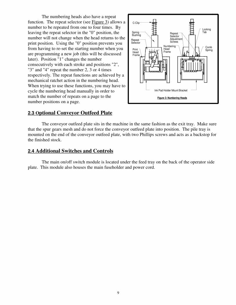
The numbering heads also have a repeat
function. The repeat selector (see Figure 3) allows a
number to be repeated from one to four times. By
leaving the repeat selector in the "0" position, the
number will not change when the head returns to the
print position. Using the "0" position prevents you
from having to re-set the starting number when you
are programming a new job (this will be discussed
later). Position "1" changes the number
consecutively with each stroke and positions "2",
"3" and "4" repeat the number 2, 3 or 4 times
respectively. The repeat functions are achieved by a
mechanical ratchet action in the numbering head.
When trying to use these functions, you may have to
cycle the numbering head manually in order to
match the number of repeats on a page to the
number positions on a page.
2.3 O ptional Conveyor Outfeed Plate
The conveyor outfeed plate sits in the machine in the same fashion as the exit tray. Make sure
that the spur gears mesh and do not force the conveyor outfeed plate into position. The pile tray is
mounted on the end of the conveyor outfeed plate, with two Phillips screws and acts as a backstop for
the finished stock.
2.4 Additional Switches and Controls
The main on/off switch module is located under the feed tray on the back of the operator side
plate. This module also houses the main fuseholder and power cord.
RepeatSelectorAdjustmentScrews
NumberingHeadFrame
Ink Pad Holder Mount Bracket
Figure 3: Numbering Heads
SpringBushing
C-Clip
RepeatSelector
PrintHeadFrame
34 2 1 0
LockingTab
CombSpring
9

3.0 Operating Keyboard
Figure 4: OPERATING KEYBOARD
The operating keyboard is comprised of six LED segments, various buttons and a Impression
Control which consist of one potentiometer knobs that control the crash strength of the numbering
heads, and can be adjusted to best suit the requirements of the job. For example, you may require
stronger crash numbering for carbonless sets than for single sheet bond paper. This adjustment can be
done while the machine is stopped or running (see Figure 4).
The four buttons under the LED display will perform whatever function is shown directly on them.
SET/FWD - Used to set up a numbering job and incrementing the motor in a forward direction.
CLR/BWD - Used to clear programs and increment
the motor backwards.
H1 - Used to control head number one, which is the
head closest to the operator.
H2 - Used to control head number two, which is the
head furthest away from the operator.
START - Used to start the machine.
STOP - Used to stop the machine.
Once you have plugged the machine in, turn the on/off switch to the 'on' position. The LED
display will be blank for a second the two lights for the safety lid and photocell will light up. The system
will do a check on each LED line segment and then look like the above.
The GW 6000 does systematic error checks, if it detects an error it will display a numeric value.
A list of all possible error codes is listed on page 21.
3.1 Running a Job
The machine is capable of storing a maximum of 1 job with 10 hits for recall and future use.
Ensure that there is paper in the feed tray first. Pressing the 'START' button will automatically begin the
program that was previously programmed in the memory.
3.2 Stopping a Job
There are two methods of stopping the machine.
1. Once the program is running, pressing the 'STOP' button will cause the machine to finish the
stock it is currently working on, move the next stock into the starting position and then stop the motor.
2. If you want to stop the machine while stock is still left in it, simply hold on to the stock in the
feed tray. After about one second, the machine will automatically stop (since it is no longer seeing any
new sheets). This is how it also stops when all of the stock in the feed tray is gone.
10
3.3 Clearing A Program
To completely clear a program from the memory insert a paper in the feed tray. Press the
SET/FWD button. The paper will then feed through and stop at 75. Press the CLR button and hold it
down, next press the H2 button and this will clear the memory.
3.4 Changing and Programming a Job
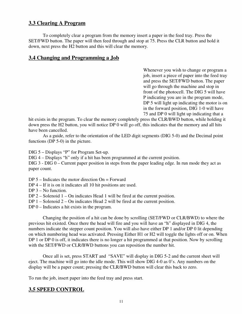
Whenever you wish to change or program a
job, insert a piece of paper into the feed tray
and press the SET/FWD button. The paper
will go through the machine and stop in
front of the photocell. The DIG 5 will have
P indicating you are in the program mode,
DP 5 will light up indicating the motor is on
in the forward position, DIG 1-0 will have
75 and DP 0 will light up indicating that a
hit exists in the program. To clear the memory completely press the CLR/BWD button, while holding it
down press the H2 button, you will notice DP 0 will go off, this indicates that the memory and all hits
have been cancelled.
As a guide, refer to the orientation of the LED digit segments (DIG 5-0) and the Decimal point
functions (DP 5-0) in the picture.
DIG 5 – Displays “P” for Program Set-up.
DIG 4 – Displays “h” only if a hit has been programmed at the current position.
DIG 3 - DIG 0 – Current paper position in steps from the paper leading edge. In run mode they act as
paper count.
DP 5 – Indicates the motor direction On = Forward
DP 4 – If it is on it indicates all 10 hit positions are used.
DP 3 – No function.
DP 2 – Solenoid 1 – On indicates Head 1 will be fired at the current position.
DP 1 – Solenoid 2 – On indicates Head 2 will be fired at the current position.
DP 0 – Indicates a hit exists in the program.
Changing the position of a hit can be done by scrolling (SET/FWD or CLR/BWD) to where the
previous hit existed. Once there the head will fire and you will have an “h” displayed in DIG 4, the
numbers indicate the stepper count position. You will also have either DP 1 and/or DP 0 lit depending
on which numbering head was activated. Pressing Either H1 or H2 will toggle the lights off or on. When
DP 1 or DP 0 is off, it indicates there is no longer a hit programmed at that position. Now by scrolling
with the SET/FWD or CLR/BWD buttons you can reposition the number hit.
Once all is set, press START and “SAVE” will display in DIG 5-2 and the current sheet will
eject. The machine will go into the idle mode. This will show DIG 4-0 as 0’s. Any numbers on the
display will be a paper count; pressing the CLR/BWD button will clear this back to zero.
To run the job, insert paper into the feed tray and press start.
3.5 SPEED CONTROL
11
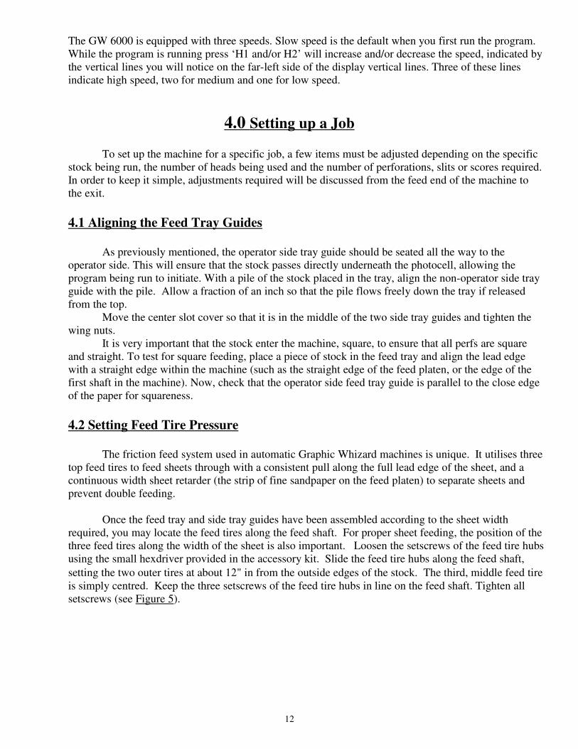
The GW 6000 is equipped with three speeds. Slow speed is the default when you first run the program.
While the program is running press ‘H1 and/or H2’ will increase and/or decrease the speed, indicated by
the vertical lines you will notice on the far-left side of the display vertical lines. Three of these lines
indicate high speed, two for medium and one for low speed.
4.0 Setting up a Job
To set up the machine for a specific job, a few items must be adjusted depending on the specific
stock being run, the number of heads being used and the number of perforations, slits or scores required.
In order to keep it simple, adjustments required will be discussed from the feed end of the machine to
the exit.
4.1 Aligning the Feed Tray Guides
As previously mentioned, the operator side tray guide should be seated all the way to the
operator side. This will ensure that the stock passes directly underneath the photocell, allowing the
program being run to initiate. With a pile of the stock placed in the tray, align the non-operator side tray
guide with the pile. Allow a fraction of an inch so that the pile flows freely down the tray if released
from the top.
Move the center slot cover so that it is in the middle of the two side tray guides and tighten the
wing nuts.
It is very important that the stock enter the machine, square, to ensure that all perfs are square
and straight. To test for square feeding, place a piece of stock in the feed tray and align the lead edge
with a straight edge within the machine (such as the straight edge of the feed platen, or the edge of the
first shaft in the machine). Now, check that the operator side feed tray guide is parallel to the close edge
of the paper for squareness.
4.2 Setting Feed Tire Pressure
The friction feed system used in automatic Graphic Whizard machines is unique. It utilises three
top feed tires to feed sheets through with a consistent pull along the full lead edge of the sheet, and a
continuous width sheet retarder (the strip of fine sandpaper on the feed platen) to separate sheets and
prevent double feeding.
Once the feed tray and side tray guides have been assembled according to the sheet width
required, you may locate the feed tires along the feed shaft. For proper sheet feeding, the position of the
three feed tires along the width of the sheet is also important. Loosen the setscrews of the feed tire hubs
using the small hexdriver provided in the accessory kit. Slide the feed tire hubs along the feed shaft,
setting the two outer tires at about 12" in from the outside edges of the stock. The third, middle feed tire
is simply centred. Keep the three setscrews of the feed tire hubs in line on the feed shaft. Tighten all
setscrews (see Figure 5).
12
If a feed tire is set too close to the edge of the sheet, its feeding efficiency will be affected by
variances in the stock such as sheet curl and inconsistent glue thickness on multiple padded forms.
Improper setting of the feed tires can cause random skewing problems.
Warning: All feed and exit tires, and
perf/score/slit boss wheels use setscrews
to secure their positions. When
tightening setscrews, do not over-tighten
them. This may scar the metal shafts
and inhibit the free sliding movement of
the feed tire hubs or perf/score/slit boss
wheels.
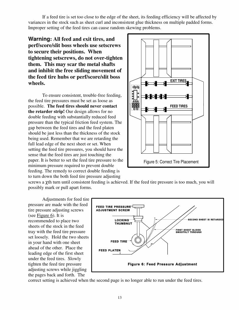
To ensure consistent, trouble-free feeding,
the feed tire pressures must be set as loose as
possible. The feed tires should never contact
the retarder strip! Our design allows for no
double feeding with substantially reduced feed
pressure than the typical friction feed system. The
gap between the feed tires and the feed platen
should be just less than the thickness of the stock
being used. Remember that we are retarding the
full lead edge of the next sheet or set. When
setting the feed tire pressures, you should have the
sense that the feed tires are just touching the
paper. It is better to set the feed tire pressure to the
minimum pressure required to prevent double
feeding. The remedy to correct double feeding is
to turn down the both feed tire pressure adjusting
screws a χth turn until consistent feeding is achieved. If the feed tire pressure is too much, you will
possibly mark or pull apart forms.
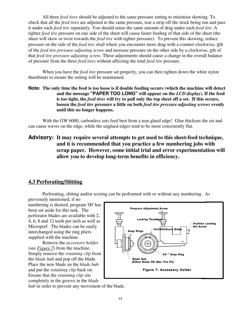
Adjustments for feed tire
pressure are made with the feed
tire pressure adjusting screws
(see Figure 6). It is
recommended to place two
sheets of the stock in the feed
tray with the feed tire pressure
set loosely. Hold the two sheets
in your hand with one sheet
ahead of the other. Place the
leading edge of the first sheet
under the feed tires. Slowly
tighten the feed tire pressure
adjusting screws while jiggling
the pages back and forth. The
correct setting is achieved when the second page is no longer able to run under the feed tires.
Figure 5: Correct Tire Placement
F1
STA
RT
32
65
1SE
TU
P
4
BAT
STO
P9
8
AC
C0
7
RE
P
ESC
SA
FET
YH
2
H1
>><<
F2
PH
OTO
CE
LL
FEED TIRES
EXIT TIRES
13
All three feed tires should be adjusted to the same pressure setting to minimise skewing. To
check that all the feed tires are adjusted to the same pressure, tear a strip off the stock being run and pass
it under each feed tire separately. You should sense the same amount of drag under each feed tire. A
tighter feed tire pressure on one side of the sheet will cause faster feeding of that side of the sheet (the
sheet will skew or twist towards the feed tire with tighter pressure). To prevent this skewing, reduce
pressure on the side of the feed tire shaft where you encounter more drag with a counter-clockwise, χth
of the feed tire pressure adjusting screw and increase pressure on the other side by a clockwise, χth of
that feed tire pressure adjusting screw. These adjustments should cause a change in the overall balance
of pressure from the three feed tires without affecting the total feed tire pressure.
When you have the feed tire pressure set properly, you can then tighten down the white nylon
thumbnuts to ensure the setting will be maintained.
Note: The only time the feed is too loose is if double feeding occurs (which the machine will detect
and the message "PAPER TOO LONG" will appear on the LCD display). If the feed
is too tight, the feed tires will try to pull only the top sheet off a set. If this occurs,
loosen the feed tire pressure a little on both feed tire pressure adjusting screws evenly
until this no longer happens.
With the GW 6000, carbonless sets feed best from a non-glued edge! Glue thickens the set and
can cause waves on the edge, while the unglued edges tend to be more consistently flat.
Advisory: It may require several attempts to get used to this sheet-feed technique,
and it is recommended that you practice a few numbering jobs with
scrap paper. However, some initial trial and error experimentation will
allow you to develop long-term benefits in efficiency.
4.3 Perforating/Slitting
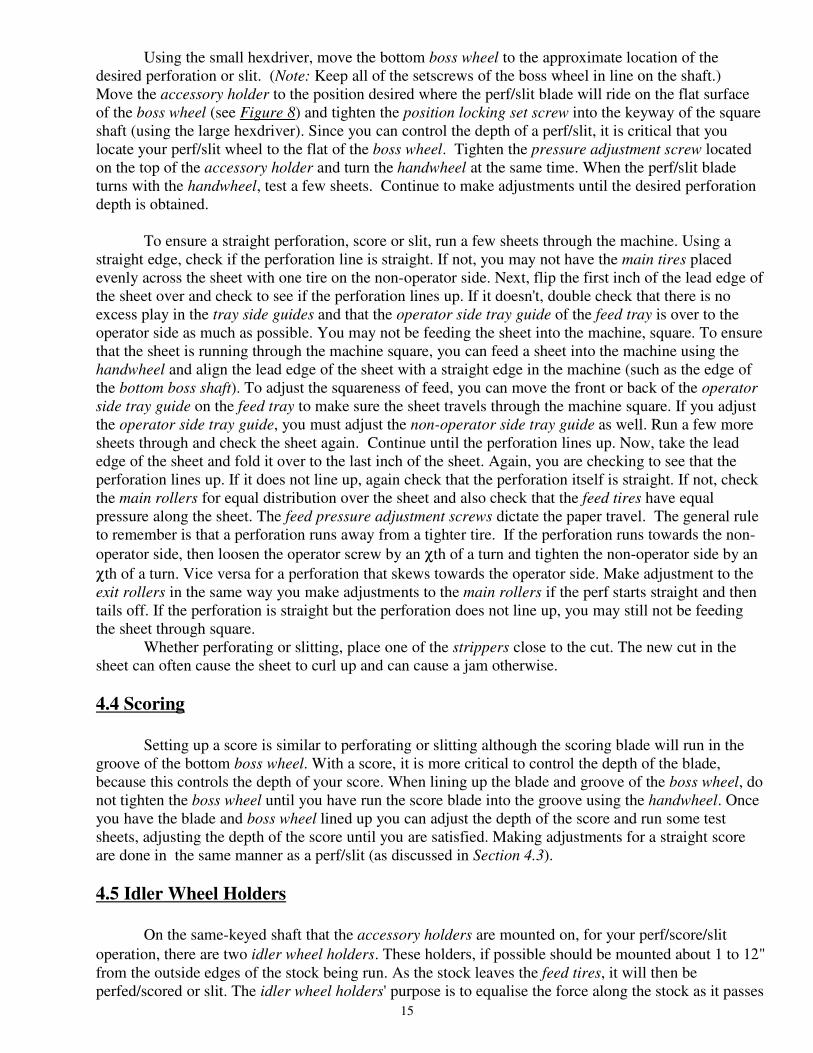
Perforating, slitting and/or scoring can be performed with or without any numbering. As
previously mentioned, if no
numbering is desired, program '00' has
been set aside for this task. The
perforator blades are available with 2,
4, 6, 8 and 12 teeth per inch as well as
Microperf. The blades can be easily
interchanged using the ring pliers
supplied with the machine.
Remove the accessory holder
(see Figure 7) from the machine.
Simply remove the retaining clip from
the blade hub and pop off the blade.
Place the new blade on the blade hub
and put the retaining clip back on.
Ensure that the retaining clip sits
completely in the groove in the blade
hub in order to prevent any movement of the blade.
14
Using the small hexdriver, move the bottom boss wheel to the approximate location of the
desired perforation or slit. (Note: Keep all of the setscrews of the boss wheel in line on the shaft.)
Move the accessory holder to the position desired where the perf/slit blade will ride on the flat surface
of the boss wheel (see Figure 8) and tighten the position locking set screw into the keyway of the square
shaft (using the large hexdriver). Since you can control the depth of a perf/slit, it is critical that you
locate your perf/slit wheel to the flat of the boss wheel. Tighten the pressure adjustment screw located
on the top of the accessory holder and turn the handwheel at the same time. When the perf/slit blade
turns with the handwheel, test a few sheets. Continue to make adjustments until the desired perforation
depth is obtained.
To ensure a straight perforation, score or slit, run a few sheets through the machine. Using a
straight edge, check if the perforation line is straight. If not, you may not have the main tires placed
evenly across the sheet with one tire on the non-operator side. Next, flip the first inch of the lead edge of
the sheet over and check to see if the perforation lines up. If it doesn't, double check that there is no
excess play in the tray side guides and that the operator side tray guide of the feed tray is over to the
operator side as much as possible. You may not be feeding the sheet into the machine, square. To ensure
that the sheet is running through the machine square, you can feed a sheet into the machine using the
handwheel and align the lead edge of the sheet with a straight edge in the machine (such as the edge of
the bottom boss shaft). To adjust the squareness of feed, you can move the front or back of the operator
side tray guide on the feed tray to make sure the sheet travels through the machine square. If you adjust
the operator side tray guide, you must adjust the non-operator side tray guide as well. Run a few more
sheets through and check the sheet again. Continue until the perforation lines up. Now, take the lead
edge of the sheet and fold it over to the last inch of the sheet. Again, you are checking to see that the
perforation lines up. If it does not line up, again check that the perforation itself is straight. If not, check
the main rollers for equal distribution over the sheet and also check that the feed tires have equal
pressure along the sheet. The feed pressure adjustment screws dictate the paper travel. The general rule
to remember is that a perforation runs away from a tighter tire. If the perforation runs towards the non-
operator side, then loosen the operator screw by an χth of a turn and tighten the non-operator side by an
χth of a turn. Vice versa for a perforation that skews towards the operator side. Make adjustment to the
exit rollers in the same way you make adjustments to the main rollers if the perf starts straight and then
tails off. If the perforation is straight but the perforation does not line up, you may still not be feeding
the sheet through square.
Whether perforating or slitting, place one of the strippers close to the cut. The new cut in the
sheet can often cause the sheet to curl up and can cause a jam otherwise.
4.4 Scoring
Setting up a score is similar to perforating or slitting although the scoring blade will run in the
groove of the bottom boss wheel. With a score, it is more critical to control the depth of the blade,
because this controls the depth of your score. When lining up the blade and groove of the boss wheel, do
not tighten the boss wheel until you have run the score blade into the groove using the handwheel. Once
you have the blade and boss wheel lined up you can adjust the depth of the score and run some test
sheets, adjusting the depth of the score until you are satisfied. Making adjustments for a straight score
are done in the same manner as a perf/slit (as discussed in Section 4.3).
4.5 Idler Wheel Holders
On the same-keyed shaft that the accessory holders are mounted on, for your perf/score/slit
operation, there are two idler wheel holders. These holders, if possible should be mounted about 1 to 12"
from the outside edges of the stock being run. As the stock leaves the feed tires, it will then be
perfed/scored or slit. The idler wheel holders' purpose is to equalise the force along the stock as it passes
15

through this section, so you do not encounter any skew, which you may encounter if you only had a
perf/score/slit wheel contacting the paper before going through the main rollers.
4.6 Main Rollers
The main rollers are comprised of a bottom solid roller with 6 and 4 adjustable rollers on top.
The top rollers are mounted on a spring-loaded shaft, to maintain pressure down to the bottom solid
roller. The adjustable top rollers must be distributed along the shaft so that there is a roller on each end
of the shaft, with the remainder distributed along the shaft. To ensure proper transport, a majority of the
rollers should be on the stock, but do not load all rollers to one end of the shaft where you may
encounter stock skew.
4.7 Installing Ink Pads
Loosen the large, star-shaped, lower knob on the drive-unit mount block and swivel the drive
unit up. This will allow you better access to the numbering head itself. Slide the repeat selector, on the
numbering head, over to the "0" position (see Figure 3 if you are unfamiliar with the components of the
numbering head). Pull down the numbering wheel frame, the ink pad mount plate swings away giving
you better access to the ink pad and exposes the numbering wheels. Now press in the locking tab which
sticks out from the top of the head frame. When you pull the numbering wheel frame down far enough,
the locking tab will drop into a groove on the numbering head shaft and hold the head in this position. If
you pull the numbering wheel frame too far down, the repeat selector may jam the head. Simply pull
the numbering wheel frame further down and press the repeat selector out of the way.
Remove an inkpad from its package (provided in the accessory kit) and grasp the two plastic
fingers on the back of the ink pad holder. Before inserting the inkpad, you must first condition the pad.
Because the pad is felt it may have swollen with ink and be thicker than need be. If inserted on the
numbering head, an inkpad with a swollen felt could cause the number wheels to get too much ink and
create splattering or fat images. To condition the inkpad, use a piece of coated stock (because it is less
absorbent) and place the inkpad on the coated stock, felt side down. Press down hard on the inkpad to
compress the felt. You can then soak up the excess ink with the pad. Once the pad is conditioned, you
gently squeeze the plastic fingers inwards on the back of the ink pad holder and slide it into the groove
on the ink pad holder plate, with the ink-reservoir side of the pad sliding in first. Release the tabs and
the holder.
4.8 Locating the Numbering Heads
To move the drive unit into the lateral position required, loosen the large star-shaped knob near
the bottom of the drive unit mount block (refer to Figure 2). Loosen the setscrew in the anti-pitch block
using the large hexdriver. This will allow you to slide the drive unit across the width of the machine.
You may now move the drive unit to the location desired. Bring the anti-pitch block over to and against
the drive unit. Now tighten the large star-shaped knob and set screw in the anti-pitch block to lock the
drive unit in place.
The anti-pitch block and drive unit mount block act together when locating a number position. If
the number position is slightly off, you can loosen one of the blocks and move it over the appropriate
distance, using the fastened block as a reference point. Also, when going to replace the inkpad, you may
move the drive unit aside, leaving the anti-pitch block in position as a reference when you wish to
continue the job.
16
To turn the numbering head so that it prints the number in the correct rotation, first loosen the
rotation lock screw on the numbering head mount block, just above the numbering head. The numbering
head will then be free to rotate to the desired orientation.
When satisfied, be sure that the head has been returned to the print position and all knobs have
been tightened.
Once you have the numbering head in the correct physical position, program the job. It is advised that
you run a few test sheets to check the strength and quality of the crash impression.
4.9 Stripper Assemblies
Each machine is supplied with a minimum of 3 stripper assemblies. Their purpose is to keep the
stock flat as it runs through the machine and to ensure that the stock does not catch on the numbering
head. The stripper blocks are to be mounted on the keyed square shaft, pointing down, and the same
shaft that the accessory holders are mounted on. They should normally be located close to the
numbering head but not underneath the numbering wheels (this can damage the numbering wheels!) or
close to where a perf/score/slit is being performed.
If you experience double images when numbering, it is possible that the stripper pressure is not
enough to keep the stock flat for the crash and the stock is bouncing, allowing a second image to occur.
If this occurs, simply bend the strippers down to create more pressure on the paper.
4.10 Setting Impression Control
After setting up the machine and then programming a job (Section 3.4), test sheets will have to
be run to verify you are getting the correct impression, in other words: number sequence; crash strength;
level impression; etc.
he Impression Control Dials, located on the control panel regulate the strength of the crash.
Simply turn the dial clockwise if more impression is required for multi-part carbonless work. Check the
bottom carbonless copies of the form to see if the impression strength is adequate. If the maximum
setting is not adequate, contact your dealer.
Reminder:Carbonless impressions are created as a development process
similar to developing a photograph. The numbering image will
continue to darken for a full twenty-four hours but will reach about
80% of its full colour in about twenty minutes. Ink chemistry, offset
powder and a number of other factors can affect both the time and the
extent of the image. Your fresh impressions will be lighter than you
want but trust them to darken. What you want to achieve is an even,
level impression with minimal or no embossing of the stock.
If making a number of impressions on the same sheet, you may have to turn up the Impression
Control to ensure a consistent crash from hit to hit. With the electric solenoid drive for the numbering
heads, jobs requiring multiple hits on a page require more work from the solenoids. A natural
consequence of an electric solenoid working more often is that the coil heats up, giving the solenoid
greater resistance to the electrical impulse. When this happens, the consequence is that the hits will get
lighter. By increasing the Impression Control, you can overcome the greater resistance the solenoid will
develop against the electrical impulse. Watching the job in progress, you will also find that the longer
17
the job, there will be a need to increase the Impression Control to maintain a consistent hit over the
whole job.
4.11 Flatness of Impression
It is best to check for the flatness of the impression on the bottom crash copy from a carbonless
set. The inked impression will not adequately show whether the impression is truly flat while the
bottom crash impression shows this quite well. Make some test impressions on carbonless, verify the
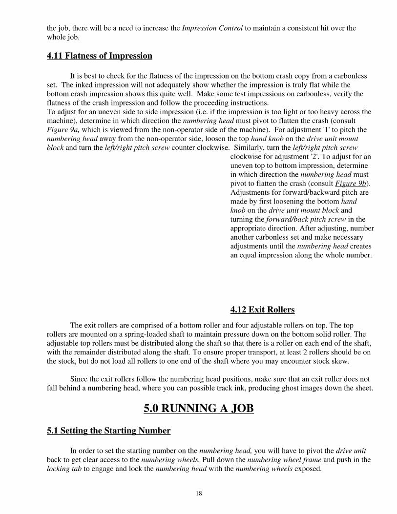
flatness of the crash impression and follow the proceeding instructions. To adjust for an uneven side to side impression (i.e. if the impression is too light or too heavy across the
machine), determine in which direction the numbering head must pivot to flatten the crash (consult
Figure 9a, which is viewed from the non-operator side of the machine). For adjustment '1' to pitch the
numbering head away from the non-operator side, loosen the top hand knob on the drive unit mount
block and turn the left/right pitch screw counter clockwise. Similarly, turn the left/right pitch screw
clockwise for adjustment '2'. To adjust for an
uneven top to bottom impression, determine
in which direction the numbering head must
pivot to flatten the crash (consult Figure 9b).
Adjustments for forward/backward pitch are
made by first loosening the bottom hand
knob on the drive unit mount block and
turning the forward/back pitch screw in the
appropriate direction. After adjusting, number
another carbonless set and make necessary
adjustments until the numbering head creates
an equal impression along the whole number.
4.12 Exit Rollers
The exit rollers are comprised of a bottom roller and four adjustable rollers on top. The top
rollers are mounted on a spring-loaded shaft to maintain pressure down on the bottom solid roller. The
adjustable top rollers must be distributed along the shaft so that there is a roller on each end of the shaft,
with the remainder distributed along the shaft. To ensure proper transport, at least 2 rollers should be on
the stock, but do not load all rollers to one end of the shaft where you may encounter stock skew.
Since the exit rollers follow the numbering head positions, make sure that an exit roller does not
fall behind a numbering head, where you can possible track ink, producing ghost images down the sheet.
5.0 RUNNING A JOB
5.1 Setting the Starting Number
In order to set the starting number on the numbering head, you will have to pivot the drive unit
back to get clear access to the numbering wheels. Pull down the numbering wheel frame and push in the
locking tab to engage and lock the numbering head with the numbering wheels exposed.
18
Each individual numbering wheel can be rotated to the appropriate starting number using the
change stick provided in the accessory kit. Remember that the standard head counts backwards so the
number that you set to start the job on will be the last number required.
If you do not require all the digits to print (ie. 0097 is desired instead of 000097), the last two
numbering wheels can be dropped from profile and locked down. To do this, rotate the numbering wheel
to the "9" position. Turn the wheel slightly past this position while also pushing down on the "9".
When the correct position is reached, the "9" will drop below type height. To restore a dropped wheel to
its regular print position, simply rotate the wheel in the regular direction and it will "pop" out of its
sunken position and back into regular print position.
Once your number has been set, and the inkpad has been installed (see Section 4.7), set the
repeat selector to "0". Now, pull the numbering wheel frame downward to release the locking tab.
Gently release the numbering wheel frame and allow it to return to its rest position. [Caution: the
numbering wheel frame is spring loaded. Once you release the locking tab, the numbering wheel frame
will spring back quickly. Please make sure that you keep your fingers clear of the inner workings of the
numbering head] If you pull the numbering wheel frame down too far and it locks, refer to Section 4.4.
If you do not return the numbering wheel frame to its rest position, the numbering head will not operate
when the machine is running, since it is already at the end of its available stroke-length. Now you can
pivot the drive unit back to the print position and re-tighten the large knob.
It is advised to set the repeat selector to '0' while running a few test sheets so that the starting
number does not change. When you are ready to start your numbering job, then change the repeat
selector to the action desired.
5.2 Setting the Repeat Selector
The numbering heads can be set to repeat a number continuously ("0"), change with every crash
("1"), or change after a number of crashes (ie. "2, 3, or 4"). This setting will depend on the type of job
required. The repeat selectors is clearly in view on the front of the numbering head and requires no
special tools to be changed (see Figure 3 ). Remember, for 2x, 3x and 4x repeat action, you may need to
run a couple of test sheets to ensure these actions match your numbering sequence, since the numbering
head is a mechanical process separate from the number position programming.
If the repeat sequence does not match the numbering sequence on your stock, you may need to
manually engage the numbering head. Push down on the numbering wheel frame as many times as it
takes to complete the repeat action, counting where the sequence was on your last test sheet.
Example: Repeat action desired is a three time action. After running a test sheet,
'9 9 8' is printed. The numbering head is in mid-sequence and to correct,
push down on the numbering wheel frame twice to complete the repeat
action. Test another sheet and the sequence printed now is '9 9 7'.
The final feeding concern is the fanning of the stock. This procedure may also take some practice, and
in particular when fanning carbonless sets across the un-glued edge. The following steps should be used
in order to fan the pile:
5.3 Fanning
1) Hold the paper as shown in Figure 10.
19
2) Lower your left hand while holding on to the pile firmly with your right hand.
3) Hold the pile tight with your left hand and loosely with the right.
4) Return the left hand to its original position.
5) Repeat steps 1 through 4 until adequate fanning is obtained.
Try fanning while holding the stack in a vertical, upright position, with the glued edge resting on
a table. This will maintain a flat, straight edge. When loading a fanned stack into the feed tires, hold
the back end of the stack up high (at approximately a 30 degree angle, relative to the feed tray) so that
the lead edge slips under the feed tires (see Figure 11). Then, gently lower the stack onto the feed tray.
Before starting the machine, rotate the handwheel one half turn and watch that the first sheet of the stack
advances correctly, while the second sheet beneath it should be retarded from feeding into the machine.
The efficiency of the feeding can be improved by increasing the spacing between the sheets of your
fanned stack. Begin with small stacks (10 to 20 sheets) and build up to larger stacks as you become
more confident with your fanning.
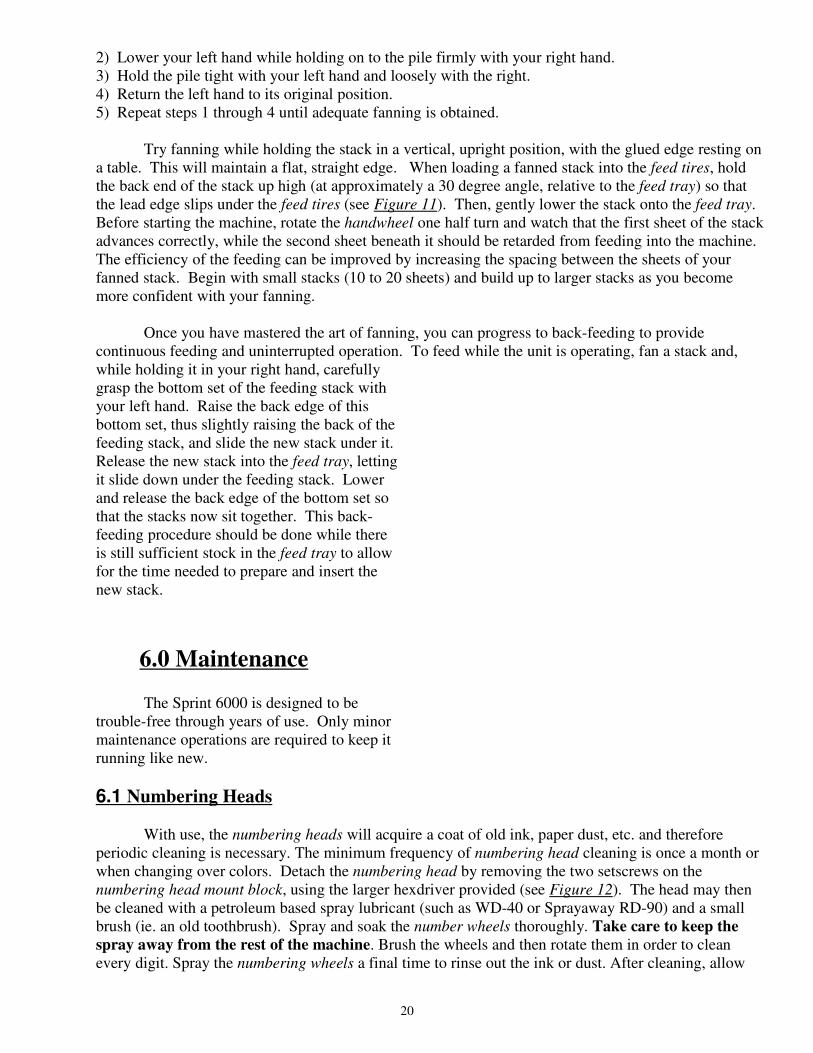
Once you have mastered the art of fanning, you can progress to back-feeding to provide
continuous feeding and uninterrupted operation. To feed while the unit is operating, fan a stack and,
while holding it in your right hand, carefully
grasp the bottom set of the feeding stack with
your left hand. Raise the back edge of this
bottom set, thus slightly raising the back of the
feeding stack, and slide the new stack under it.
Release the new stack into the feed tray, letting
it slide down under the feeding stack. Lower
and release the back edge of the bottom set so
that the stacks now sit together. This back-
feeding procedure should be done while there
is still sufficient stock in the feed tray to allow
for the time needed to prepare and insert the
new stack.
6.0 Maintenance
The Sprint 6000 is designed to be
trouble-free through years of use. Only minor
maintenance operations are required to keep it
running like new.
6.1 Numbering Heads
With use, the numbering heads will acquire a coat of old ink, paper dust, etc. and therefore
periodic cleaning is necessary. The minimum frequency of numbering head cleaning is once a month or
when changing over colors. Detach the numbering head by removing the two setscrews on the
numbering head mount block, using the larger hexdriver provided (see Figure 12). The head may then
be cleaned with a petroleum based spray lubricant (such as WD-40 or Sprayaway RD-90) and a small
brush (ie. an old toothbrush). Spray and soak the number wheels thoroughly. Take care to keep the
spray away from the rest of the machine. Brush the wheels and then rotate them in order to clean
every digit. Spray the numbering wheels a final time to rinse out the ink or dust. After cleaning, allow
20
the head to dry completely (ie. leave it standing overnight) or blow it dry with compressed air. Wipe the
head and reinstall.
Important: Do not use solvents. Solvents will strip out the lubricants from the head,
allow corrosion and impair the correct functioning of the print head.
6.2 Machine Cleaning
After each job, or midway through a very large job, clean the feed tires. You can use warm water
to clean off paper dust or drying powder, or blanket wash or alcohol if there is ink on the feed tires. Any
type of rubber roller rejuvenator is also good to clean the feed tires, the rejuvenator will also soften the
rubber. This will prevent glazing of the rubber. Brand new tires will require extra cleaning for the first
job or two until the rubber beds in.
In addition, always watch that paper dust or dirt does not block the photocell sensor eyes. The “green”
light on the control panel marked “PHOTOCELL” can verify correct photocell operation. If dirty,
simply wipe the photocell sensor eyes but do not use solvents. Either use a cotton swab or blow clean
with compressed air.
Ensure that the trays and guides are clean.
6.3 Lubrication
The Sprint 6000 utilises ten oil-impregnated bronze bushings to support all shafts. An occasional
drop of light machine oil will maintain their lubricating qualities. Wipe off any excess oil to avoid
spoiling a job.
6.4 Friction Feed
Over time, the rubber components of the feed tires may wear or harden. Use a rubber roller
rejuvenator occasionally to soften the rubber. Other than the feed tires, another important element of the
friction feed system is the full lead edge-retarding strip. The abrasive agent on the retarding strip
prevents sheets from double feeding. As the abrasive agent wears, you will encounter more double feeds
and when you see the green backing of the retarding strip you must replace it. To replace the retarding
strip for the feed, adjust the feed shaft to its highest position. Using a scribe or sharp edge, etch into the
feed platen where the retarding strip ends (you will use this scribed mark as a reference point when you
apply the new retarding strip). Peel off the old retarding strip(you may need a knife or razor) and
remove any old adhesive with alcohol. Replace with a new self-adhesive retarding strip. Make sure that
there is some of the retarding strip surface under the feed tires to ensure proper operation.
21

7.0 TROUBLESHOOTING
SYMPTOM SOLUTION
Friction Feeder
Double-Feeding Adjust feed tires down by an χ turn (feed is too loose); if the
retarding strip is glazed or worn (you can see the green
backing), replace retarding strip (see Section 6.4)
Creasing, marking, Adjust feed tires up by an χ turn (feed is too tight)
or sets pulled apart
Kicking, turning Balance adjustment on feed shaft required (one side is too
tight); adjust feed tray guides closer together to eliminate
side to side play (see Section 4.1 & 4.2 for adjustment
instructions).
Not feeding paper Feed may be too lose in which case, multiple sheets are
jammed under the feed tires, check adjustment; if feed tires
are smooth or glazed, clean, rejuvenate or replace; open
feed tray guides (set too tight to paper width and pinching
stock)
Print Quality
Uneven crash Adjust for crash flatness (see Section 4.11)
impression
Faint colour or uneven Replace ink pad. (see Section 4.7)
colour impression
Excessive inking Clean head (see Section 6.1); condition ink pad (see
Section 4.7) or replace leaking ink pad.
22
Too heavy (embossing) Adjust Impression Control dial. (see Section 4.10);
or too light a crash check platen pad, if there is excessive wear, the
platen pad may require replacing.
Ink spreading, smudging Numbering machine ink is mineral oil with pigment.
or not drying The oil is absorbed by the paper leaving the pigment
behind as the image. On slick or glossy stocks, the supplied
inkpad will not work effectively. Non-corrosive ink must
be used as a substitute (such as fountain pen ink). An
important factor with alternative inks is that the numbering
heads be cleaned immediately after a job has been run.
Registration
Inconsistent number Check that the photocell is clear of any obstacles (see
location (poor number Section 6.2); if the number location seems to 'float',
registration) the feed tray guides may be too loose allowing sheets to
skew as they feed (this will be seen more often with
number locations closer to the non-operator side, furthest
away from where the sheet passes the photocell; if numbers
occur all over the place, the photocell may require
readjustment (it is too sensitive, mis-registering the lead
edge of the sheet)
Perf/score/slit line With a straight edge, check that the perf/score/slit is
skewing straight. If straight, the stock is not feeding square and
the feed tray guides may need adjusting to ensure the
stock enters square into the machine. If the perf/score/
slit line is not straight but is bowed or has a tail whip,
the rollers on the main shaft and/or the exit shaft may
not be evenly balanced along the shaft, causing
uneven pressure on one side of the stock. This causes
a skew and the rollers must be evenly spaced across
the shaft. A bowed line usually indicates the rollers on
the main shaft are uneven, and a tail whip usually
means the rollers on the exit shaft are uneven.
Numbering Heads
The numbering heads creating an impression are a mechanical process separate from
the programming of the machine. If encountering problems with the correct operation
of the numbering head, such as numbering wheels not turning, numbers partially
printing, numbering wheels turning out of sequence, etc. the repeat selector or other
23
components may be out of alignment (refer to Figure 4). Being a mechanical process,
alignment of the individual parts is very important. Remove the numbering head from
the machine. Pressing down on the numbering head shaft, you will see the numbering
head frame slide down the print head frame. While this happens, the ink pad holder
mount bracket will swing away, exposing the numbering wheels (see Figure D).
The numbering wheels and repeat action ratchet wheels are mounted on a keyed
shaft inside the numbering head frame. The wheels are then held in place, and
refrained from spinning by the retaining pawls, which are forced to the numbering
wheel flats by the comb spring. The retaining pawls must be aligned with the flats of
the numbering wheels, or what looks like in between the numbering wheels. The comb
spring must also apply a constant pressure against the retaining pawls. Consequently
this alignment not in effect is that the numbering wheels may spin freely, causing
partial impression or random numbering sequences.
Like the retaining pawls, the changeover pawls of the repeat selector must also be
aligned to the flats of the numbering wheels. When an impression is made, the
numbering wheel frame is propelled down the print head frame. The ink pad holder
mount bracket swings away, the repeat selector is pushed back from the numbering
wheels and the numbering wheels are then exposed to make their impression on the
stock. After reaching the bottom of its stroke, the numbering wheel frame then returns
to the top position. As this happens, the repeat selector's changeover pawls once again
come into contact with the numbering wheel flats. Depending upon the action or
sequence in place, the repeat pawl may only interact with one of the repeat action
ratchet wheels before the changeover pawls interact with the .numbering wheel flats.
In most instances, the longest changeover pawl comes into contact with the flat of the
unit wheel flat to change it over. After a "0" has been printed, there will be more
changeover pawls changing more numbering wheels. When this happens, you may
find the next impression, with a "9" as the last digit, printing lightly. This can be
overcome by increasing the Impression Control to provide a stronger pulse to turn
over more wheels. If you are encountering problems where numbers are not turning
over, numbers are printed out of sequence, etc., then the problem may be that the
changeover pawls of the repeat selector are not aligned with the flats of the
numbering wheels.
The repeat selector is mounted
on the print head frame by the
two repeat selector adjustment
screws. The repeat selector must
be mounted to the print head
frame squarely. If not, the
changeover pawls will not engage
the flats of the numbering wheels
square, in this case some of the
changeover pawls can not change
their numbering wheels. Visually,
check that the changeover pawls
24

are riding in-between the numbering wheels, centred on their flats. If not, the whole
repeat selector may be moved to the proper position by loosening the repeat selector
adjustment screws. Lastly, the changeover pawls must be parallel to each other.
Error Codes
Group Condition Error
Paper Handing Errors 01 PAPER JAM
05 MSTP PAPER ERROR REPORTED IS UNDEFINED
03 PAPER TO LONG
02-04, 06-09 Reserved
Solenoid Errors 10 CH1 OPEN
11 CH1 SHORT
12 CH1 HOT
13 CH2 OPEN
14 CH2 SHORT
15 CH2 HOT
16 CH1 2 HEADS
17 CH2 2 HEADS
18 NO SOLENOID BOARD ATTACHED
19 LOW VOLTAGE SOLENOID BOARD ATTACHED
20 SOLENOID TIMEOUT
21 SOLENOID BOARD TYPE INCONSISTENT (BETWEEN MSTP AND ICPU)
22 SOLENOID ADC LIMITS ARE INCONSISTENT (BETWEEN MSTP AND ICPU)
23-28 Reserved
29 MSTP REPORTED UNKNOWN SOLENOID ERROR
Motor Errors 30 MOTOR RUN TIMEOUT
31 MOTOR TURN ON/OFF TIMEOUT
32-39 Reserved
EEPROM Errors 40 UNABLE TO READ FROM EEPROM
41 UNABLE TO WRITE TO EEPROM
42 CRC INVALID FOR EEPROM PROGRAMMABLE PARAMETERS
43 CHECKSUM INVALID FOR EEPROM SOLENOID PROGRAM
44 TESTING FAILED DURING TEST/RE-FORMAT EEPROM
45 EEPROM VERSION FORMAT ID# DOES NOT MATCH SOFTWARE
44-49 Reserved
Memory Errors 50 RAM SELF-TEST READ/WRITE FAILURE
51 CHECKSUM INVALID FOR RAM SOLENOID PROGRAM
52 CRC INVALID FOR RAM PROGRAMMABLE PARAMETERS
53 SETUP MODE SOLENOID PROGRAM HIT INDEX OUT OF RANGE
54 SOLENOID PROGRAM NUMBER IS CORRUPT
55-59 Reserved
Hardware Errors 60 AC LINE VOLTAGE OUT OF OPERATION RANGE
61 MOTOR VOLTAGE OUT OF OPERATION RANGE
62-69 Reserved
SCI Errors 70 ICPU SCI RECEIVE TIMEOUT ERROR
71 ICPU SCI RECEIVE OVERFLOW ERROR
72 ICPU SCI TRANSMIT TIMEOUT ERROR
73 ICPU SCI INVALID ACK RECEIVED
74 ICPU SCI CORRUPTED MESSAGE RECEIVED
75 ICPU SCI TRANSMIT ABORTED
25

76 ICPU SCI WATING PERIOD FOR MSTP MESSAGE EXPIRED
77 ICPU SCI INVALID MESSAGE TYPE RECEIVED
80 MSTP SCI RECEIVE TIMEOUT ERROR
81 MSTP SCI RECEIVE OVERFLOW ERROR
82 MSTP SCI TRANSMIT TIMEOUT ERROR
83 MSTP SCI INVALID ACK RECEIVED
84 MSTP SCI INVALID COMMAND RECEIVED
85 MSTP RECEIVE OVERRUN ERROR
86 MSTP RECEIVE FRAMING ERROR
77-79, 87-88 Reserved
89 MSTP SCI ERROR REPORTED IS UNDEFINED
Miscellaneous 90 MSTP ERROR REPORTED IS UNDEFINED
GW 6000 PARTS LIST
PART NO. 6K DESCRIPTION
10-001-GW X Black, Preinked Pad w/holder
10-002-GW X Black, Preinked Pad w/holder
10-003-GW X Uninked pad w/holder
10-004-GW X Felt Insert
10-005-GW X Red Ink, 4 oz. bottle
10-006-GW X Black Ink, 4 oz. bottle
10-007-GW X Changestick
10-008-GW X 3/32" Hexdriver
10-009-GW X 5/32" Hexdriver
10-010-GW X Ring Pliers
10-011-GW X ¾" Snap Ring
10-012-GW X Reverse Numbering Head (6 digits, 2 drop)
10-013-GW X Forward Numbering Head (6 digits, 5 drop)
10-014-GW X Condensed Reverse Numbering Head (8 digits, 4 drop)
10-015-GW X Date Stamp Head (month/day/year)
10-016-GW X 5/8" Wave Washer
10-017-GW X Feed Tray
10-018-GW X Feed Tray Side Guides
10-019-GW X Feed Tray Slot Cover
10-020-GW X Locking Wingnuts
10-021-GW X Feed Platen Retarding Strip
10-022-GW X Feed Shaft Adjust Screw
10-023-GW X Locking Thumbnut
10-024-GW X Roller Tire (feed/main/exit)
10-025-GW X Roller Hub
10-026-GW X Roller Shaft
10-027-GW X 3/8 " Set Screw Collar
10-028-GW X Shaft Bushing
10-029-GW X Feed Shaft Bushing w/Spring
10-030-GW X Shaft Bushing w/Spring
10-031-GW X Solid Bottom Roller
10-032-GW X Main Platen Crash Pad
10-033-GW X Main Platen
10-034-GW X Main Platen Grommets
10-035-GW X Main Platen Mount Brackets
26

10-040-GW X Hand Knob
10-041-GW X 5/16" Disc Spring
10-042-GW X 5/16" Flat Washer
10-043-GW X Solenoid w/plunger
10-044-GW X Solenoid plunger
10-053-GW X Drive Unit Cover
10-054-GW X Print Head Mount Block
10-055-GW X Exit Tray
10-056-GW X Magnetic Tray Side Guides
10-057-GW X Magnets (2)
10-058-GW X Handwheel
10-059-GW X 120V Modular Line Cord
10-066-GW X 5A, 250V Slow Blow Fuse
10-068-GW X Impression Control Dial Knob
10-071-GW X ½ “ Cord Strain Relief
10-084-GW X Accessory Holder w/12 TPI perf blade
10-085-GW X Accessory Holder Adjust Screw
10-086-GW X Blade Mount Hub w/bearing
10-088-GW X Accessory Holder w/idler wheel
10-089-GW X Idler Wheel Tire
10-090-GW X Boss Wheel
10-091-GW X 2 TPI Perf. Blade
10-092-GW X 4 TPI Perf. Blade
10-093-GW X 6 TPI Perf. Blade
10-094-GW X 8 TPI Perf. Blade
10-095-GW X 12 TPI Perf. Blade
10-096-GW X Microperf (42 TPI) Blade
10-097-GW X Microperf (72 TPI) Blade
10-098-GW X Slit Blade
10-099-GW X Score Blade
10-100-GW X Narrow Score Blade
10-101-GW X Double Score (1/4 " separation) w/Holder & Boss
15-005-GW X Red Quick Drying Ink, 2 oz. Bottle
15-006-GW X Black Quick Drying Ink, 2 oz. Bottle
15-036-GW X ¾ “ Keyed Drive Unit Mount Shaft
15-037-GW X Anti-Pitch Block
15-038-GW X 5/16” Dogged Set Screws
15-039-GW X Drive Unit Mount Block (left/right pitch control)
15-052-GW X Solenoid Mount Angle w/tube (left/right pitch)
15-072-GW X Complete Drive Unit
15-073-GW X Complete Drive Unit w/Reverse #ing Head
30-025-GW X Large Clutch Feed Pulley /12k
30-037-GW X Rubber Foot
40-003-GW X Timing Pulley- 18XL037X3/8
40-103-GW X Timing Pulley- 18XL037X1/2
50-007-GW X Main Structure Shaft
50-008-GW X Feed Platen/8000
50-009-GW X Shaft Adjust Blocks
50-011-GW X Drive Unit Mount Shaft Bracket
50-014-GW X Boss Wheel Shaft
50-019-GW X Cross Shaft
50-020-GW X Exit Rollers Safety Shield
50-021-GW X Timing Belt- 220XL037
50-022-GW X Belt Tensioner
27

50-023-GW X 1 ¾ “ Feed Pulley
50-033-GW X Fan Guard
50-035-GW OP Stand/8000
50-037-GW OP Regular Caster Wheel
50-038-GW OP Locking Caster Wheel
90-001-GW X Non-Operator Side Plate
90-002-GW X Operator Side Plate
90-003-GW X Non-Operator Side Cover w/guard
90-004-GW X Operator Side Cover
90-005-GW X Stepper Motor
90-006-GW X Motor Ferrite Bead
90-007-GW X Motor Guard
90-009-GW X Metal Display Panel
90-010-GW X Main Bottom Roller
90-011-GW X Photocell Reflector
90-012-GW X Accessory Holder Mount Shaft
90-013-GW X Stripper Assembly
90-015-GW X Safety Shield w/hinge & actuator /3/6/8k
90-016-GW X Safety Switch w/harness /3/6/8k
90-024-GW X O-Ring Feed Drive Belt/3/6/8k
90-028-GW X HV Voltage Solenoid Board 3/6k
90-028-GW-X X HV Voltage Solenoid Board 3/6k: Exchange
90-031-GW X Low Profile Tie Mounts
90-032-GW X 12V Cooling Fan
90-054-GW X Print Head Mount Screws
90-055-GW X Print Head Rotation Screw
90-059-GW X 220V Line Cord
90-060-GW X MSTP Board 120V Connector
90-061-GW X MSTP Board 220V Connector
90-062-GW X Modular Switch w/fuseholder
90-063-GW X Line Filter
90-064-GW X Filter to MSTP Board Cable
90-065-GW X Board Mount Stand-Off
90-067-GW X Photocell Assembly
90-069-GW X Solenoid Connection: Board to Female Terminal
90-082-GW X Wire Transfer Tube
90-083-GW X Drive Shaft Bearing
90-084-GW X Drive Shaft Bearing w/Spring
90-085-GW X Plastic Electrical Guard
92-025-GW X MSTP Board
92-025-GW-X X MSTP Board: Exchange
92-026-GW X MSTP Chip
92-027-GW X ICPU EPROM
92-028-GW X HV Voltage Solenoid Board
92-028-GW-X X HV Voltage Solenoid Board: Exchange
92-029-GW X ICPU Display Board
92-029-GW-X X ICPU Display Board: Exchange
92-030-GW X Red Screen Cover
92-034-GW X Display Board Label/6k
94-003-GW X Non-Operator Side Cover w/guard
28

GW 6000 PARTS DIAGRAM
29

30

31

32

33