Embed Size (px)
DESCRIPTION
s
Citation preview

GW-1
GLASSES, WINDOW SYSTEM & MIRRORS
I BODY
CONTENTS
C
D
E
F
G
H
J
K
L
M
SECTION
A
B
GW
Revision: July 2005 2005 Sentra
PRECAUTIONS .......................................................... 2Precautions for Supplemental Restraint System (SRS) “AIR BAG” and “SEAT BELT PRE-TEN-SIONER” .................................................................. 2
WINDSHIELD AND WINDOWS .................................. 3Removal and Installation .......................................... 3
REMOVAL ............................................................. 3INSTALLATION ..................................................... 3WINDSHIELD AND REAR WINDOW ................... 5QUARTER WINDOW ............................................ 6
POWER WINDOW ...................................................... 7System Description .................................................. 7
MANUAL OPERATION ......................................... 7AUTO OPERATION .............................................. 8POWER WINDOW LOCK ..................................... 8
Wiring Diagram — WINDOW — .............................. 9Trouble Diagnoses ..................................................11
FRONT DOOR GLASS AND REGULATOR ............ 12Front Door .............................................................. 12
REAR DOOR GLASS AND REGULATOR ............... 13Rear Door ............................................................... 13
DOOR MIRROR ........................................................ 14Wiring Diagram — MIRROR — .............................. 14Wiring Diagram — H/MIRR — ............................... 15Removal and Installation ........................................ 16
REAR WINDOW DEFOGGER .................................. 17
Component Parts and Harness Connector Location ... 17System Description ................................................. 18
WITHOUT POWER DOOR LOCKS .................... 18WITH POWER DOOR LOCKS ............................ 18
Wiring Diagram — DEF — ..................................... 20CONSULT-II Inspection Procedure (With Power Door Locks) ............................................................ 22
“REAR DEFOGGER” .......................................... 22CONSULT-II Application Items (With Power Door Locks) ..................................................................... 23
“REAR DEFOGGER” .......................................... 23Trouble Diagnoses (Without Power Door Locks) ... 24
DIAGNOSTIC PROCEDURE .............................. 24Trouble Diagnoses (With Power Door Locks) ........ 26
DIAGNOSTIC PROCEDURE .............................. 26Electrical Components Inspection .......................... 30
REAR WINDOW DEFOGGER RELAY ................ 30REAR WINDOW DEFOGGER SWITCH ............. 30
Filament Check ....................................................... 30Filament Repair ...................................................... 31
REPAIR EQUIPMENT ......................................... 31REPAIRING PROCEDURE ................................. 31
REAR VIEW MIRROR ............................................... 33Removal and Installation ........................................ 33
REMOVAL ........................................................... 33INSTALLATION ................................................... 33

GW-2
PRECAUTIONS
Revision: July 2005 2005 Sentra
PRECAUTIONS PFP:00001
Precautions for Supplemental Restraint System (SRS) “AIR BAG” and “SEAT BELT PRE-TENSIONER” EIS0015U
The Supplemental Restraint System such as “AIR BAG” and “SEAT BELT PRE-TENSIONER”, used alongwith a front seat belt, helps to reduce the risk or severity of injury to the driver and front passenger for certaintypes of collision. Information necessary to service the system safely is included in the SRS and SB section ofthis Service Manual.WARNING:● To avoid rendering the SRS inoperative, which could increase the risk of personal injury or death
in the event of a collision which would result in air bag inflation, all maintenance must be per-formed by an authorized NISSAN/INFINITI dealer.
● Improper maintenance, including incorrect removal and installation of the SRS, can lead to per-sonal injury caused by unintentional activation of the system. For removal of Spiral Cable and AirBag Module, see the SRS section.
● Do not use electrical test equipment on any circuit related to the SRS unless instructed to in thisService Manual. SRS wiring harnesses can be identified by yellow and/or orange harness connec-tors.

WINDSHIELD AND WINDOWS
GW-3
C
D
E
F
G
H
J
K
L
M
A
B
GW
Revision: July 2005 2005 Sentra
WINDSHIELD AND WINDOWS PFP:72700
Removal and Installation EIS0015V
REMOVALAfter removing interior moldings and trim to access edge of glass,remove glass using piano wire or power cutting tool and an inflatablepump bag.WARNING:When removing the glass from the vehicle, always wear safetyglasses and heavy gloves to help prevent glass splinters fromentering your eyes or cutting your hands.CAUTION:● Be careful not to scratch the glass when removing.● Do not set or stand the glass on its edge. Small chips may
develop into cracks.
INSTALLATION● Use genuine Nissan Urethane Adhesive Kit or equivalent and follow the instructions furnished with it.● While the urethane adhesive is curing, open a door window. This will prevent the glass from being forced
out by passenger compartment air pressure when a door is closed.● The molding must be installed securely so that it is in position and leaves no gap.● Inform the customer that the vehicle should remain stationary until the urethane adhesive has completely
cured (preferably 24 hours). Curing time varies with temperature and humidity.WARNING:● Keep heat and open flames away as primers and adhesive are flammable.● The materials contained in the kit are harmful if swallowed, and may irritate skin and eyes. Avoid
contact with the skin and eyes.● Use in an open, well ventilated location. Avoid breathing the vapors. They can be harmful if
inhaled. If affected by vapor inhalation, immediately move to an area with fresh air.● Driving the vehicle before the urethane adhesive has completely cured may affect the perfor-
mance of the windshield in case of an accident.
SBF034B
ABT088
ABT087

GW-4
WINDSHIELD AND WINDOWS
Revision: July 2005 2005 Sentra
CAUTION:● Do not use an adhesive which is past its usable term. Shelf life of this product is limited to six
months after the date of manufacture. Carefully adhere to the expiration or manufacture dateprinted on the box.
● Keep primers and adhesive in a cool, dry place. Ideally, they should be stored in a refrigerator.● Do not leave primers or adhesive cartridge unattended with their caps open or off.● The vehicle should not be driven for at least 24 hours or until the urethane adhesive has com-
pletely cured. Curing time varies depending on temperature and humidities. The curing time willincrease under lower temperatures and lower humidities.

WINDSHIELD AND WINDOWS
GW-5
C
D
E
F
G
H
J
K
L
M
A
B
GW
Revision: July 2005 2005 Sentra
WINDSHIELD AND REAR WINDOW
Repairing Water Leaks for WindshieldLeaks can be repaired without removing and reinstalling glass.If water is leaking between caulking material and body or glass, determine the extent of leakage. Thiscan be determined by applying water while pushing glass outward.To stop the leak, apply primer and then sealant to the leak point.
WBT114

GW-6
WINDSHIELD AND WINDOWS
Revision: July 2005 2005 Sentra
QUARTER WINDOW
1. Remove the rear door finisher. Refer to EI-31, "Removal and Installation" .2. Lower the rear window.3. Remove two screws securing rear glass, then remove rear glass.4. Remove two bolts and one top screw securing rear door center sash, then remove rear door center sash.5. Remove quarter glass and rubber seal.
WBT074

POWER WINDOW
GW-7
C
D
E
F
G
H
J
K
L
M
A
B
GW
Revision: July 2005 2005 Sentra
POWER WINDOW PFP:25401
System Description EIS0015W
Power is supplied at all times:● from 30A fusible link (letter d , located in the fuse and fusible link box)● to circuit breaker terminal +,● through circuit breaker terminal -,● to power window relay terminal 5.With ignition switch in ON or START position, power is supplied:● through 10A fuse [No. 10, located in the fuse block (J/B)],● to power window relay terminal 1.Ground is supplied:● to power window relay terminal 2● through body grounds M28 and M54.The power window relay is energized and power is supplied:● through power window relay terminal 3,● to main power window and door lock/unlock switch terminal 1,● to front power window switch RH terminal 5,● to rear power window switch LH and RH terminal 5.
MANUAL OPERATIONFront Door LHGround is supplied:● to main power window and door lock/unlock switch terminal 3,● through body grounds M28 and M54.WINDOW UPWhen the front LH switch in the main power window and door lock/unlock switch is pressed in the up position,power is supplied:● to front power window motor LH terminal UP,● through main power window and door lock/unlock switch terminal 9.Ground is supplied:● to front power window motor LH terminal DN,● through main power window and door lock/unlock switch terminal 8.Then, the motor raises the window until the switch is released, or until the window reaches the end of its travel.WINDOW DOWNWhen the LH switch in the main power window and door lock/unlock switch is pressed in the down position,power is supplied:● to front power window motor LH terminal DN,● through main power window and door lock/unlock switch terminal 8.Ground is supplied:● to front power window motor LH terminal UP,● through main power window and door lock/unlock switch terminal 9.Then, the motor lowers the window until the switch is released, or until the window reaches the end of itstravel.
Front Door RHGround is supplied:● to main power window and door lock/unlock switch terminal 3,● through body grounds M28 and M54.NOTE:Numbers in parentheses are terminal numbers, when power window switch is pressed in the UP and DOWNpositions respectively.
GW-8
POWER WINDOW
Revision: July 2005 2005 Sentra
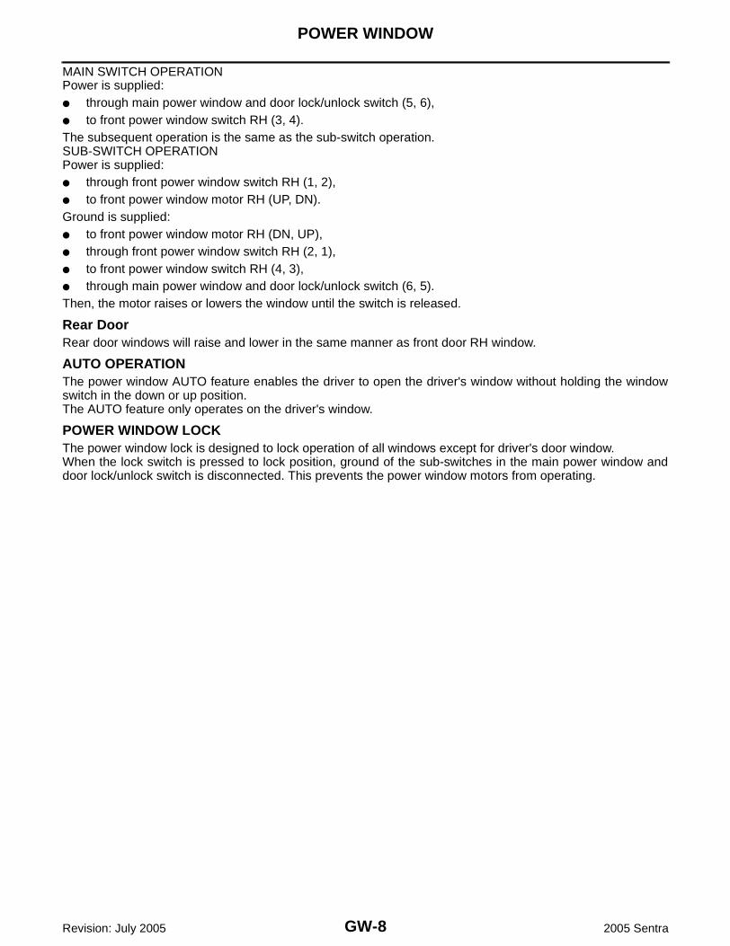
MAIN SWITCH OPERATIONPower is supplied:● through main power window and door lock/unlock switch (5, 6),● to front power window switch RH (3, 4).The subsequent operation is the same as the sub-switch operation.SUB-SWITCH OPERATIONPower is supplied:● through front power window switch RH (1, 2),● to front power window motor RH (UP, DN).Ground is supplied:● to front power window motor RH (DN, UP),● through front power window switch RH (2, 1),● to front power window switch RH (4, 3),● through main power window and door lock/unlock switch (6, 5).Then, the motor raises or lowers the window until the switch is released.
Rear DoorRear door windows will raise and lower in the same manner as front door RH window.
AUTO OPERATIONThe power window AUTO feature enables the driver to open the driver's window without holding the windowswitch in the down or up position.The AUTO feature only operates on the driver's window.
POWER WINDOW LOCKThe power window lock is designed to lock operation of all windows except for driver's door window.When the lock switch is pressed to lock position, ground of the sub-switches in the main power window anddoor lock/unlock switch is disconnected. This prevents the power window motors from operating.
POWER WINDOW
GW-9
C
D
E
F
G
H
J
K
L
M
A
B
GW
Revision: July 2005 2005 Sentra
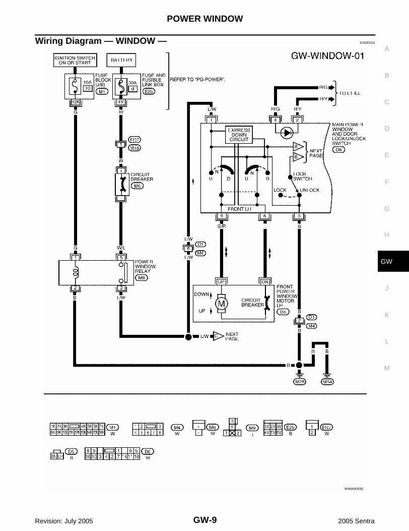
Wiring Diagram — WINDOW — EIS0015X
WIWA0093E

GW-10
POWER WINDOW
Revision: July 2005 2005 Sentra
WIWA1213E

POWER WINDOW
GW-11
C
D
E
F
G
H
J
K
L
M
A
B
GW
Revision: July 2005 2005 Sentra
Trouble Diagnoses EIS0015Y
Symptom Possible cause Repair order
None of the power windows can be operated using any switch.
1. 10A fuse, 30A fusible link
2. M6 circuit breaker
3. Power window relay
4. M6 circuit breaker and power win-dow relay related wiring
5. Ground circuit
6. Main power window and door lock/unlock switch
1. Check 10A fuse [No. 10, located in fuse block (J/B)], 30A fusible link (letter d , located in fuse and fusible link box).
2. Check M6 circuit breaker.
3. Check power window relay.
4. Check the following.
– Check harness between M6 circuit breaker and 30A fusible link (letter d , located in fuse and fusible link box).
– Check harness between M6 circuit breaker and power window relay.
– Check harness between power window relay and power window relay main power window and door lock/unlock switch.
– Check harness between 10A fuse [No. 10, located in fuse block (J/B)] and power window relay.
5. Check the following.
– Check ground circuit of main power window and door lock/unlock switch terminal 3.
– Check power window relay ground circuit.
6. Check main power window and door lock/unlock switch.
Driver side power window cannot be operated but other windows can be operated.
1. Driver side power window regula-tor circuit
2. Driver side power window regula-tor
3. Main power window and door lock/unlock switch circuit
4. Main power window and door lock/unlock switch
1. Check harness between main power window and door lock/unlock switch and driver side power window regu-lator for open or short circuit.
2. Check driver side power window regulator.
3. Check harness between power window relay and main power window and lock/unlock switch.
4. Check main power window and door lock/unlock switch.
One or more power windows except driver's side window cannot be operated.
1. Power window sub-switches
2. Power window regulators
3. Main power window and door lock/unlock switch
4. Power window circuit
1. Check power window sub-switch.
2. Check power window regulator.
3. Check main power window and door lock/unlock switch.
4. Check the following.
– Check harness between the power window sub switch terminal 5 and power window relay.
– Check harnesses between main power window and door lock/unlock switch and power window sub-switch for open/short circuit.
– Check harnesses between power window sub-switch and power window regulator for open/short circuit.
Power windows except driver's side window cannot be operated using main power window and door lock/unlock switch but can be operated by power window sub-switch.
1. Main power window and door lock/unlock switch
1. Check main power window and door lock/unlock switch.

GW-12
FRONT DOOR GLASS AND REGULATOR
Revision: July 2005 2005 Sentra
FRONT DOOR GLASS AND REGULATOR PFP:80300
Front Door EIS0015Z
● For removal of door finisher, refer to EI-31, "Removal and Installation" .● After adjusting the door or door lock, check the door lock operation.
WIIA0006E

REAR DOOR GLASS AND REGULATOR
GW-13
C
D
E
F
G
H
J
K
L
M
A
B
GW
Revision: July 2005 2005 Sentra
REAR DOOR GLASS AND REGULATOR PFP:82300
Rear Door EIS00160
WIIA0002E

GW-14
DOOR MIRROR
Revision: July 2005 2005 Sentra
DOOR MIRROR PFP:96301
Wiring Diagram — MIRROR — EIS00161
WIWA1214E
DOOR MIRROR
GW-15
C
D
E
F
G
H
J
K
L
M
A
B
GW
Revision: July 2005 2005 Sentra
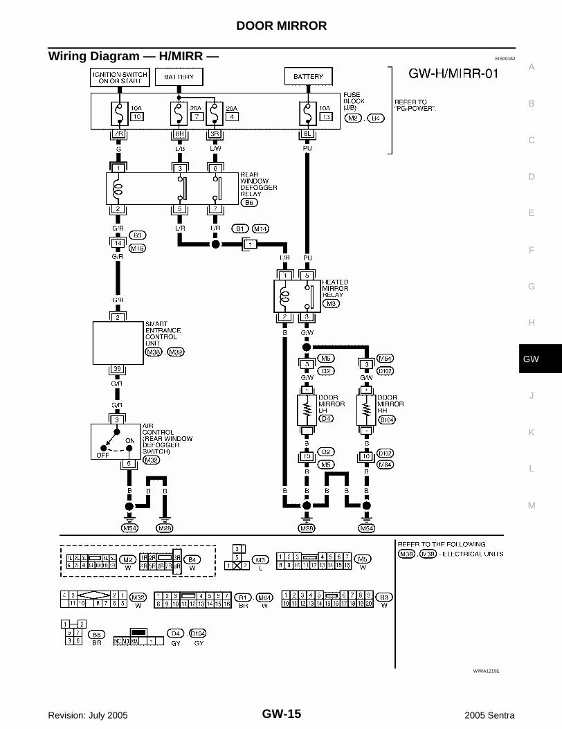
Wiring Diagram — H/MIRR — EIS00162
WIWA1215E

GW-16
DOOR MIRROR
Revision: July 2005 2005 Sentra
Removal and Installation EIS00163
CAUTION:Be careful not to scratch door mirror body.1. Remove door finisher. Refer to EI-31, "Removal and Installation" .2. Remove inner cover from front corner of door.3. Disconnect door mirror harness connector.4. Remove three nuts securing door mirror assembly.
WBT052
REAR WINDOW DEFOGGER
GW-17
C
D
E
F
G
H
J
K
L
M
A
B
GW
Revision: July 2005 2005 Sentra
REAR WINDOW DEFOGGER PFP:25350
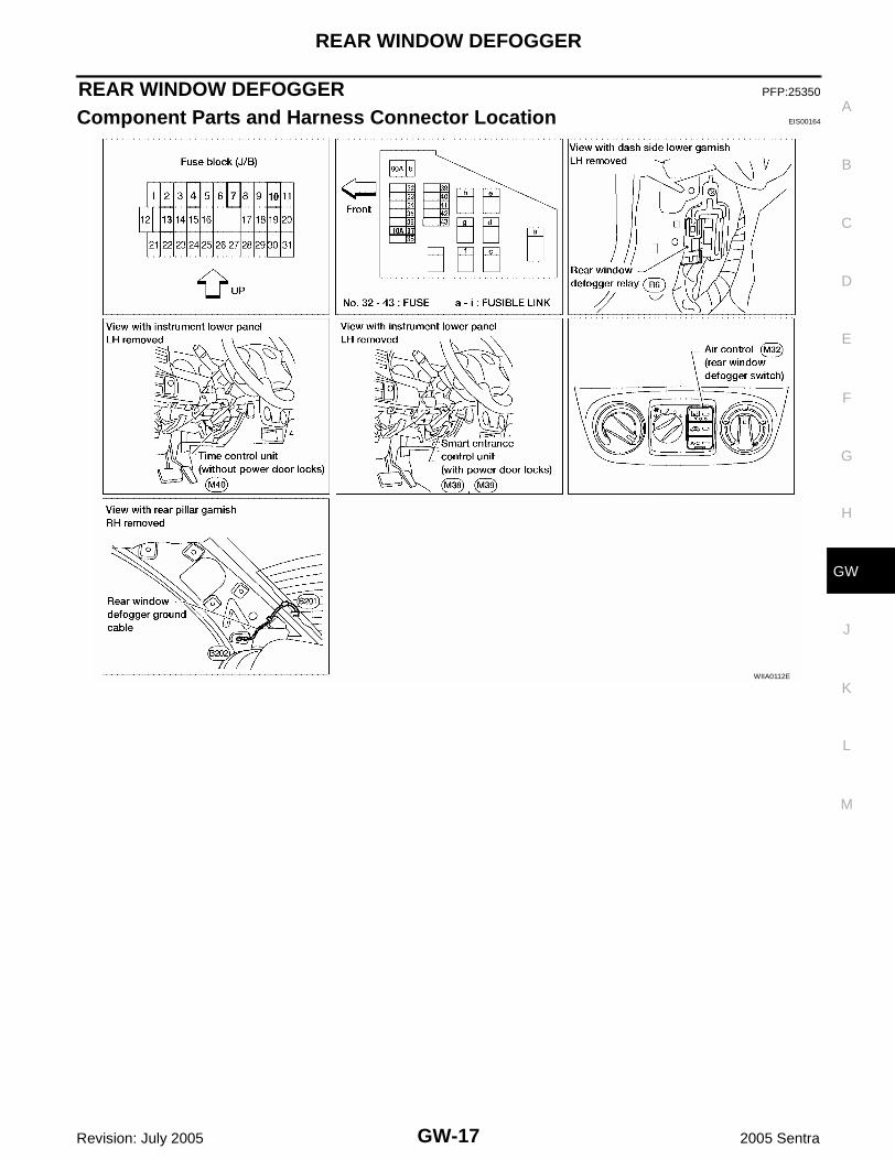
Component Parts and Harness Connector Location EIS00164
WIIA0112E
GW-18
REAR WINDOW DEFOGGER
Revision: July 2005 2005 Sentra
System Description EIS00165
WITHOUT POWER DOOR LOCKSThe rear window defogger system is controlled by the time control unit. The rear window defogger operates forapproximately 15 minutes.Power is supplied at all times:● to rear window defogger relay terminal 3● through 20A fuse [No. 7, located in the fuse block (J/B)],● to rear window defogger relay terminal 6● through 20A fuse [No. 4, located in the fuse block (J/B)], and● to time control unit terminal 7● through 10A fuse [No. 13, located in the fuse block (J/B)].With the ignition switch in the ON or START position, power is supplied:● through 10A fuse [No. 10, located in the fuse block (J/B)]● to the rear window defogger relay terminal 1, and● to time control unit terminal 9.Ground is supplied to terminal 5 of the rear window defogger switch (built into the air control) through bodygrounds M28 and M54.When the rear defogger switch is turned ON, ground is supplied:● through terminal 3 of the rear window defogger switch● to time control unit terminal 3.Terminal 10 of the time control unit then supplies ground to the rear window defogger relay terminal 2.With power and ground supplied, the rear window defogger relay is energized.Power is supplied:● through terminals 5 and 7 of the rear window defogger relay● to the rear window defogger.The rear window defogger has an independent ground.With power and ground supplied, the rear window defogger filaments heat and defog the rear window.When the system is activated, the rear window defogger indicator illuminates in the rear window defoggerswitch.Power is supplied:● to terminal 4 of the rear window defogger switch● from terminals 5 and 7 of the rear window defogger relay.Terminal 5 of the rear window defogger switch is grounded through body grounds M28 and M54.
WITH POWER DOOR LOCKSThe rear window defogger system is controlled by the smart entrance control unit. The rear window defoggeroperates for approximately 15 minutes.Power is supplied at all times:● to rear window defogger relay terminal 3● through 20A fuse [No. 7, located in the fuse block (J/B)],● to rear window defogger relay terminal 6● through 20A fuse [No. 4, located in the fuse block (J/B)], and● to smart entrance control unit terminal 10● through 10A fuse (No. 37, located in the fuse and fusible link box).With the ignition switch in the ON or START position, power is supplied:● through 10A fuse [No. 10, located in the fuse block (J/B)]● to the rear window defogger relay terminal 1, and● to smart entrance control unit terminal 33.Ground is supplied to terminal 5 of the rear window defogger switch (built into the air control) through bodygrounds M28 and M54.When the rear defogger switch is turned ON, ground is supplied:● through terminal 3 of the rear window defogger switch
REAR WINDOW DEFOGGER
GW-19
C
D
E
F
G
H
J
K
L
M
A
B
GW
Revision: July 2005 2005 Sentra
● to smart entrance control unit terminal 39.Terminal 2 of the smart entrance control unit then supplies ground to the rear window defogger relay terminal2.With power and ground supplied, the rear window defogger relay is energized.Power is supplied:● through terminals 5 and 7 of the rear window defogger relay● to the rear window defogger.The rear window defogger has an independent ground.With power and ground supplied, the rear window defogger filaments heat and defog the rear window.When the system is activated, the rear window defogger indicator illuminates in the rear window defoggerswitch.Power is supplied:● to terminal 4 of the rear window defogger switch● from terminals 5 and 7 of the rear window defogger relay.Terminal 5 of the rear window defogger switch is grounded through body grounds M28 and M54.

GW-20
REAR WINDOW DEFOGGER
Revision: July 2005 2005 Sentra
Wiring Diagram — DEF — EIS00166
WIWA0311E

REAR WINDOW DEFOGGER
GW-21
C
D
E
F
G
H
J
K
L
M
A
B
GW
Revision: July 2005 2005 Sentra
WIWA0037E

GW-22
REAR WINDOW DEFOGGER
Revision: July 2005 2005 Sentra
TIME CONTROL UNIT TERMINALS AND REFERENCE VALUE MEASURED BETWEEN EACH TERMINAL AND GROUND (WITH-OUT POWER DOOR LOCKS)
SMART ENTRANCE CONTROL UNIT TERMINALS AND REFERENCE VALUE MEASURED BETWEEN EACH TERMINAL ANDGROUND (WITH POWER DOOR LOCKS)
CONSULT-II Inspection Procedure (With Power Door Locks) EIS00167
“REAR DEFOGGER”CAUTION:If CONSULT-II is used with no connection of CONSULT-II CONVERTER, malfunctions might bedetected in self-diagnosis depending on control unit which carry out CAN communication. 1. Turn ignition switch OFF.2. Connect “CONSULT-II” and CONSULT-II CONVERTER to data
link connector.
TERMINAL WIRE COLOR ITEM CONDITION DATA (DC)
3 G/BAIR CONTROL (REAR WIN-DOW DEFOGGER SWITCH)
OFF 5V
ON 0V
7 PU POWER SOURCE (FUSE) — 12V
8 B GROUND — —
9 G
IGNITION SWITCH (ON) IGNITION KEY IN ON POSITION 12V
IGNITION SWITCH (START)IGNITION KEY IN START POSI-TION
12V
10 G/RREAR WINDOW DEFOGGER RELAY
OFF 0V
ON (IGNITION KEY IN ON POSI-TION)
12V
TERMINAL WIRE COLOR ITEM CONDITION DATA (DC)
2 G/RREAR WINDOW DEFOGGER RELAY
OFF 0V
ON (IGNITION KEY IN ON POSI-TION)
12V
10 PU POWER SOURCE (FUSE) — 12V
16 B GROUND — —
33 G
IGNITION SWITCH (ON) IGNITION KEY IN ON POSITION 12V
IGNITION SWITCH (START)IGNITION KEY IN START POSI-TION
12V
39 G/BAIR CONTROL (REAR WIN-DOW DEFOGGER SWITCH)
OFF 5V
ON 0V
LAT136
REAR WINDOW DEFOGGER
GW-23
C
D
E
F
G
H
J
K
L
M
A
B
GW
Revision: July 2005 2005 Sentra
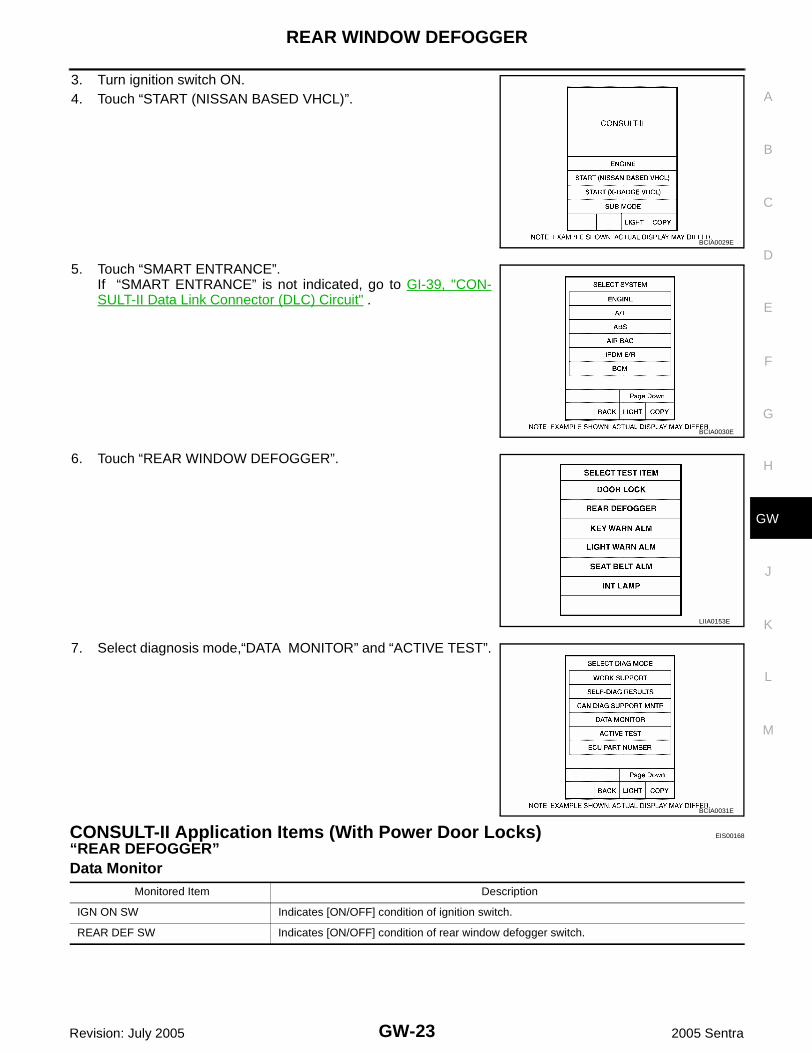
3. Turn ignition switch ON.4. Touch “START (NISSAN BASED VHCL)”.
5. Touch “SMART ENTRANCE”.If “SMART ENTRANCE” is not indicated, go to GI-39, "CON-SULT-II Data Link Connector (DLC) Circuit" .
6. Touch “REAR WINDOW DEFOGGER”.
7. Select diagnosis mode,“DATA MONITOR” and “ACTIVE TEST”.
CONSULT-II Application Items (With Power Door Locks) EIS00168
“REAR DEFOGGER”Data Monitor
BCIA0029E
BCIA0030E
LIIA0153E
BCIA0031E
Monitored Item Description
IGN ON SW Indicates [ON/OFF] condition of ignition switch.
REAR DEF SW Indicates [ON/OFF] condition of rear window defogger switch.

GW-24
REAR WINDOW DEFOGGER
Revision: July 2005 2005 Sentra
Active Test
Trouble Diagnoses (Without Power Door Locks) EIS00169
DIAGNOSTIC PROCEDURESymptom: Rear Window Defogger Does Not Activate, or Does Not Go Off After Deactivating.
1. CHECK REAR WINDOW DEFOGGER OUTPUT SIGNAL
1. Turn ignition switch to ON position.2. Check voltage between time control unit harness connector M40
terminal 10 (G/R) and ground.
OK or NGOK >> Check the following.
● Refer to GW-30, "Filament Check" .NG >> GO TO 2.
2. CHECK DEFOGGER RELAY COIL SIDE CIRCUIT
1. Disconnect time control unit harness connector M40.2. Turn ignition switch to ON position.3. Check voltage between time control unit harness connector M40
terminal 10 (G/R) and ground.
OK or NGOK >> GO TO 3.NG >> Check the following.
● 10A fuse [No. 10, located in the fuse block (J/B)]● Rear window defogger relay● Harness for open or short between 10A fuse [No. 10,
located in the fuse block (J/B)] and rear window defogger relay● Harness for open or short between rear window defogger relay and time control unit
Test Item Description
REAR DEFOGGERThis test is able to check rear window defogger operation. Rear window defogger activates when “ON” on CONSULT-II screen is touched.
Voltage (V) Approx.:Rear window defogger switch is "OFF"
: 12V
Rear window defogger switch is "ON"
: 0V
WIIA0041E
Battery voltage should exist.
WIIA0042E

REAR WINDOW DEFOGGER
GW-25
C
D
E
F
G
H
J
K
L
M
A
B
GW
Revision: July 2005 2005 Sentra
3. CHECK REAR WINDOW DEFOGGER SWITCH INPUT SIGNAL
Check continuity between time control unit harness connector M40terminal 3 (G/B) and ground.
OK or NGOK >> GO TO 4.NG >> Check the following.
● Rear window defogger switch(Refer to GW-30, "REAR WINDOW DEFOGGER SWITCH" .)
● Harness for open or short between time control unit and rear window defogger switch● Rear window defogger switch ground circuit
4. CHECK POWER SUPPLY AND IGNITION INPUT SIGNAL
Check voltage between time control unit harness connector M40 ter-minals 7 (PU), 9 (G) and ground.
OK or NGOK >> GO TO 5.NG >> Check the following.
● 10A fuse [No. 10 or No. 13, located in the fuse block (J/B)]● Harness for open or short between time control unit and fuse
5. CHECK TIME CONTROL UNIT GROUND CIRCUIT
Check continuity between time control unit harness connector M40terminal 8 and ground.
Yes >> Replace time control unit.No >> Repair harness or connectors.
Continuity:Rear window defogger switch is pushed.
Continuity should exist.
Rear window defogger switch is released.
Continuity should not exist.
WIIA0043E
TerminalsIgnition switch position
(+) (-) OFF ACC ON
7 GroundBattery volt-age
Battery volt-age
Battery volt-age
9 Ground0V 0V
Battery volt-age
WIIA0044E
Continuity should exist.
WIIA0045E
GW-26
REAR WINDOW DEFOGGER
Revision: July 2005 2005 Sentra
Trouble Diagnoses (With Power Door Locks) EIS0016A
DIAGNOSTIC PROCEDURESymptom: Rear Window Defogger Does Not Activate, or Does Not Go Off After Activating.
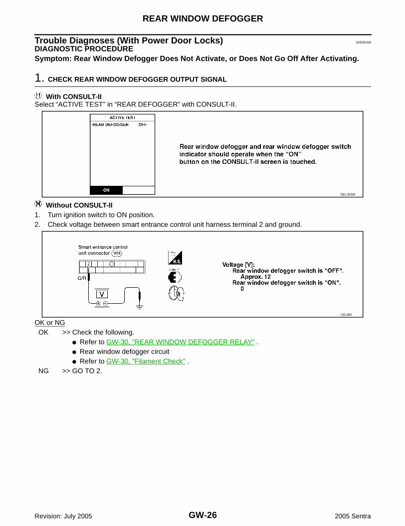
1. CHECK REAR WINDOW DEFOGGER OUTPUT SIGNAL
With CONSULT-IISelect “ACTIVE TEST” in “REAR DEFOGGER” with CONSULT-II.
Without CONSULT-II1. Turn ignition switch to ON position.2. Check voltage between smart entrance control unit harness terminal 2 and ground.
OK or NGOK >> Check the following.
● Refer to GW-30, "REAR WINDOW DEFOGGER RELAY" .● Rear window defogger circuit● Refer to GW-30, "Filament Check" .
NG >> GO TO 2.
SEL353W
LEL482

REAR WINDOW DEFOGGER
GW-27
C
D
E
F
G
H
J
K
L
M
A
B
GW
Revision: July 2005 2005 Sentra
2. CHECK DEFOGGER RELAY COIL SIDE CIRCUIT
1. Disconnect control unit connector.2. Turn ignition switch to ON position.3. Check voltage between smart entrance control unit terminal 2 and ground.
OK or NGOK >> GO TO 3.NG >> Check the following.
● 10A fuse [No. 10, located in the fuse block (J/B)]● Rear window defogger relay● Harness for open or short between 10A fuse [No. 10, located in the fuse block (J/B)] and rear
window defogger relay● Harness for open or short between rear window defogger relay and smart entrance control unit
LEL483
GW-28
REAR WINDOW DEFOGGER
Revision: July 2005 2005 Sentra
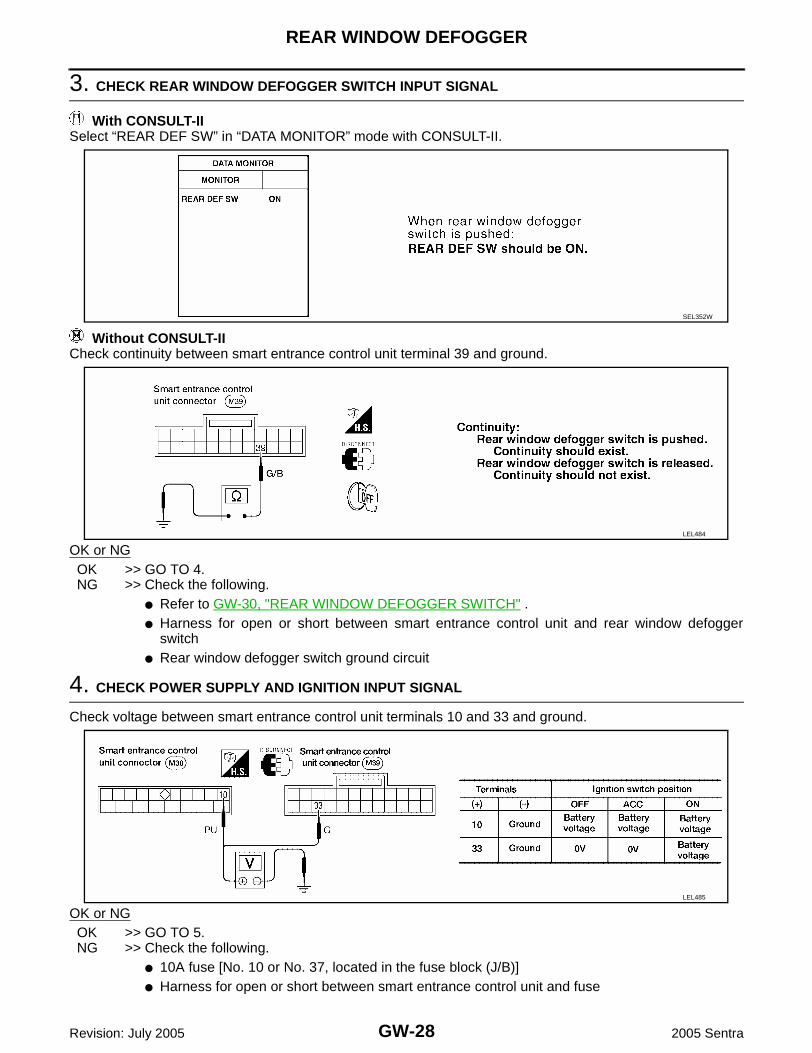
3. CHECK REAR WINDOW DEFOGGER SWITCH INPUT SIGNAL
With CONSULT-IISelect “REAR DEF SW” in “DATA MONITOR” mode with CONSULT-II.
Without CONSULT-IICheck continuity between smart entrance control unit terminal 39 and ground.
OK or NGOK >> GO TO 4.NG >> Check the following.
● Refer to GW-30, "REAR WINDOW DEFOGGER SWITCH" .● Harness for open or short between smart entrance control unit and rear window defogger
switch● Rear window defogger switch ground circuit
4. CHECK POWER SUPPLY AND IGNITION INPUT SIGNAL
Check voltage between smart entrance control unit terminals 10 and 33 and ground.
OK or NGOK >> GO TO 5.NG >> Check the following.
● 10A fuse [No. 10 or No. 37, located in the fuse block (J/B)]● Harness for open or short between smart entrance control unit and fuse
SEL352W
LEL484
LEL485
REAR WINDOW DEFOGGER
GW-29
C
D
E
F
G
H
J
K
L
M
A
B
GW
Revision: July 2005 2005 Sentra
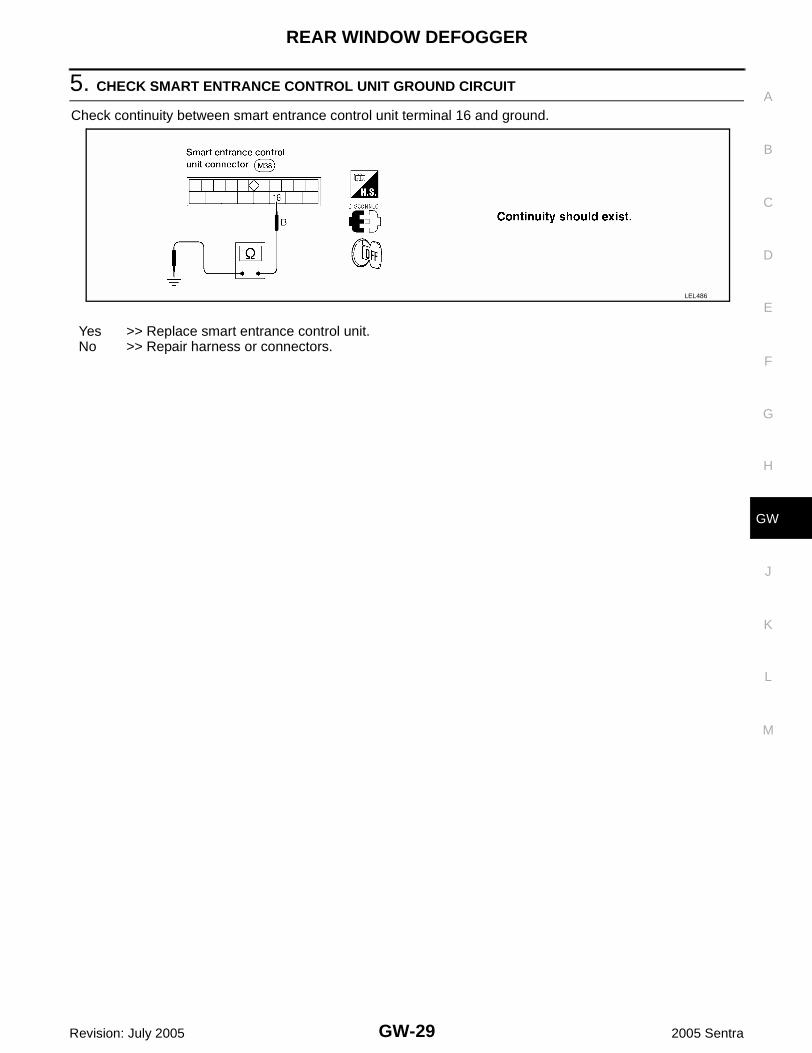
5. CHECK SMART ENTRANCE CONTROL UNIT GROUND CIRCUIT
Check continuity between smart entrance control unit terminal 16 and ground.
Yes >> Replace smart entrance control unit.No >> Repair harness or connectors.
LEL486

GW-30
REAR WINDOW DEFOGGER
Revision: July 2005 2005 Sentra
Electrical Components Inspection EIS0016B
REAR WINDOW DEFOGGER RELAYCheck continuity between terminals 3 and 5, 6 and 7.
REAR WINDOW DEFOGGER SWITCHWith air control (rear window defogger switch) connector M32 dis-connected, check continuity between terminals 3 and 5 when rearwindow defogger switch is pushed and released.
Filament Check EIS0016C
1. Attach probe circuit tester (in volt range) to middle portion ofeach filament.
● When measuring voltage, wrap tin foil around the top ofthe negative probe. Then press the foil against the wirewith your finger.
Condition Continuity
12V direct current supply between termi-nals 1 and 2
Yes
No current supply No
SEC202B
TerminalsCondition Continuity
(+) (-) Switch pushed Yes
3 5 Switch released No
WIIA0105E
SEL263
SEL122R
REAR WINDOW DEFOGGER
GW-31
C
D
E
F
G
H
J
K
L
M
A
B
GW
Revision: July 2005 2005 Sentra
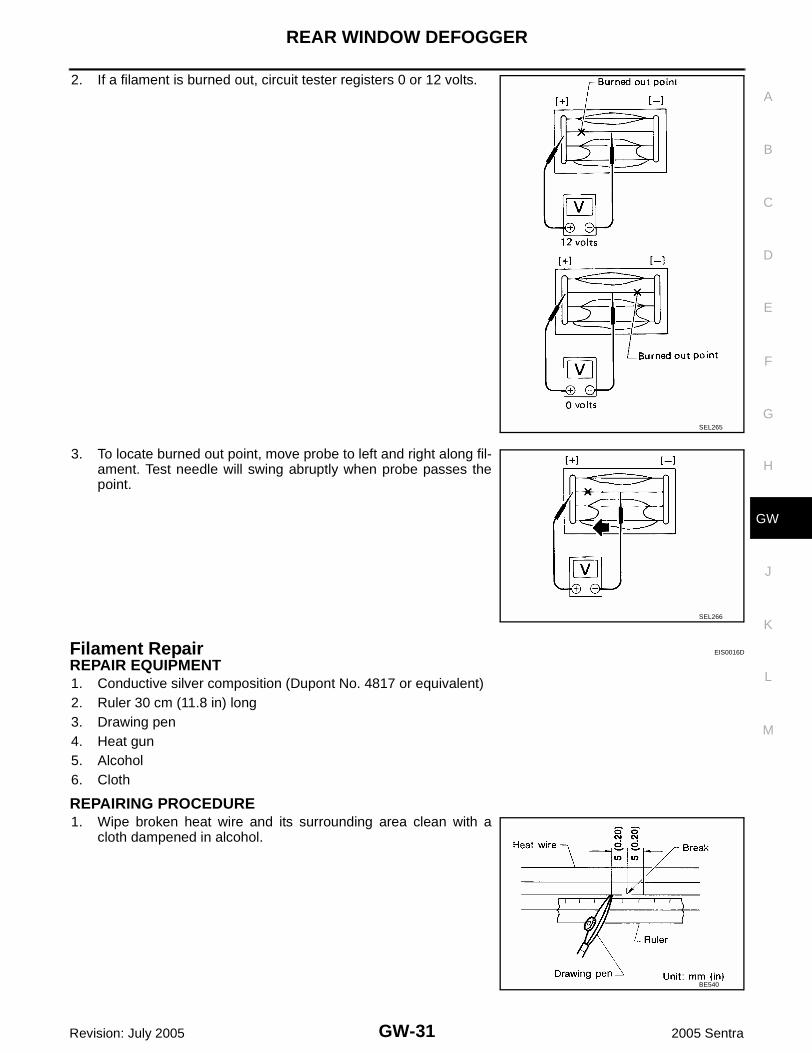
2. If a filament is burned out, circuit tester registers 0 or 12 volts.
3. To locate burned out point, move probe to left and right along fil-ament. Test needle will swing abruptly when probe passes thepoint.
Filament Repair EIS0016D
REPAIR EQUIPMENT1. Conductive silver composition (Dupont No. 4817 or equivalent)2. Ruler 30 cm (11.8 in) long3. Drawing pen4. Heat gun5. Alcohol6. Cloth
REPAIRING PROCEDURE1. Wipe broken heat wire and its surrounding area clean with a
cloth dampened in alcohol.
SEL265
SEL266
BE540

GW-32
REAR WINDOW DEFOGGER
Revision: July 2005 2005 Sentra
2. Apply a small amount of conductive silver composition to tip of drawing pen.Shake silver composition container before use.3. Place ruler on glass along broken line. Deposit conductive silver composition on break with drawing pen.
Slightly overlap existing heat wire on both sides [preferably 5 mm (0.20 in)] of the break.4. After repair has been completed, check repaired wire for conti-
nuity. This check should be conducted 10 minutes after silvercomposition is deposited.
Do not touch repaired area while test is being conducted.5. Apply a constant stream of hot air directly to the repaired area
for approximately 20 minutes with a heat gun. A minimum dis-tance of 3 cm (1.2 in) should be kept between repaired area andhot air outlet. If a heat gun is not available, let the repaired areadry for 24 hours.
SEL012D
SEL013D

REAR VIEW MIRROR
GW-33
C
D
E
F
G
H
J
K
L
M
A
B
GW
Revision: July 2005 2005 Sentra
REAR VIEW MIRROR PFP:96321
Removal and Installation EIS0016E
REMOVALRemove rear view mirror by pushing deflect spring with screwdriver as shown in the figure.
INSTALLATION1. Install mounting bracket as follows:a. Determine mounting bracket position on windshield by measur-
ing from top of windshield to top of mounting bracket as shownin the figure.
b. Mark location on outside of windshield with wax pencil or equiv-alent.
c. Clean attaching point on inside of windshield with an alcohol-saturated paper towel.
d. Sand bonding surface of mounting bracket with sandpaper (No.320 or No. 360).
e. Clean bonding surface of mounting bracket with an alcohol-satu-rated paper towel.
f. Apply Genuine Mirror Adhesive or equivalent to bonding surface of mounting bracket. Refer to GI-46,"RECOMMENDED CHEMICAL PRODUCTS AND SEALANTS" .
g. Install mounting bracket at pre-marked position and press mounting bracket against glass for 30 to 60seconds.
h. After five minutes, wipe off excess adhesive with an alcohol-moistened paper towel.2. Install rear view mirror.
SBT821
SBT822

GW-34
REAR VIEW MIRROR
Revision: July 2005 2005 Sentra