Embed Size (px)
Citation preview
GV-N94TOC-1GI/GV-N94TOC-512I/GV-N94T-512INVIDIA® GeForceTM 9400 GT Graphics Accelerator
User's ManualRev. 10312MM-N94TOC-103R
Copyright© 2009 GIGABYTE TECHNOLOGY CO., LTDCopyright by GIGA-BYTE TECHNOLOGY CO., LTD. ("GBT"). No part of this manual may be reproduced or transmittedin any form without the expressed, written permission of GBT.TrademarksThird-party brands and names are the properties of their respective owners.NoticePlease do not remove any labels on this graphics card. Doing so may void the warranty of this card.Due to rapid change in technology, some of the specifications might be out of date before publication of this this manual.The author assumes no responsibility for any errors or omissions that may appear in this document nor does the authormake a commitment to update the information contained herein.Macrovision corporation product notice:This product incorporates copyright protection technology that is protected by U.S. patents and other intellectual propertyrights. Use of this copyright protection technology must be authorized by Macrovision, and is intended for home and otherlimited viewing uses only unless otherwise authorized by Macrovision. Reverse engineering or disassembly is prohibited.
VG
A C
ardG
V-N
94TO
C-1G
I/G
V-N
94TO
C-512I
Oct. 24, 2008
Oct. 24, 2008
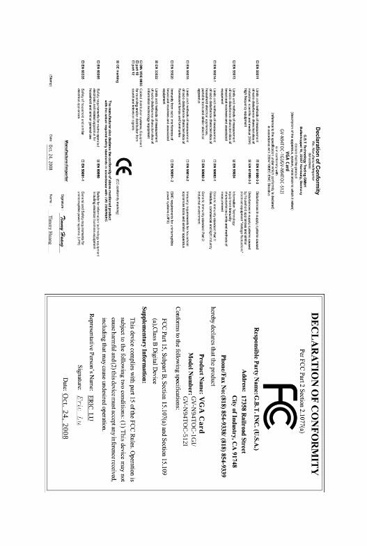
VGA CardGV-N94TOC-1GI/GV-N94TOC-512I

VG
A C
ard
GV
-N94T-512I
Dec. 25, 2008
Dec. 25, 2008
VGA CardGV-N94T-512I
- 4 -
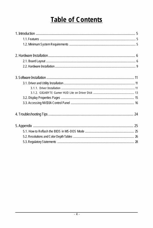
Table of Contents
1. Introduction ................................................................................................................ 51.1. Features ......................................................................................................................... 51.2. Minimum System Requirements .................................................................................... 5
2. Hardware Installation .................................................................................................. 62.1. Board Layout ................................................................................................................. 62.2. Hardware Installation ...................................................................................................... 9
3. Software Installation ................................................................................................... 113.1. Driver and Utility Installation .......................................................................................... 11
3.1.1. Driver Installation .......................................................................................................... 113.1.2. GIGABYTE Gamer HUD Lite on Driver Disk ........................................................... 13
3.2. Display Properties Pages ............................................................................................ 153.3. Accessing NVIDIA Control Panel ................................................................................ 16
4. Troubleshooting Tips ................................................................................................ 24
5. Appendix ................................................................................................................. 255.1. How to Reflash the BIOS in MS-DOS Mode .............................................................. 255.2. Resolutions and Color Depth Tables ............................................................................. 265.3. Regulatory Statements ................................................................................................. 28
- 5 - Introduction
1. Introduction1.1. Features
• Powered by NVIDIA® GeForceTM 9400 GT Graphics Processing Unit (GPU)• Supports PCI Express 2.0• Integrated with 1 GB GDDR2 memory (For GV-N94TOC-1GI only)• Integrated with 512 MB GDDR2 memory (For GV-N94TOC-512I/GV-N94T-512I only)• Supports DirectX 10• Supports 2 HDMI connectors (1 by optional adapter)• Supports 1 D-Sub connector• Supports 1 Dual-Link DVI-I connector• Supports HDCP (High-Bandwidth Digital Content Protection) technology
1.2. Minimum System Requirements• Hardware
- Intel® Pentium®/CoreTM 2 or AMD AthlonTM/PhenomTM
- 128 MB of system memory; 2 GB or more for best performance- Optical drive for software installation (CD-ROM or DVD-ROM drive)- A power supply with 300-watt is recommended
• Operating System- Windows® Vista- Windows® XP with Service Pack 2 (SP2)- Windows® XP Professional x64 Edition
- 6 -GV-N94T Series Graphics Accelerator
2. Hardware Installation2.1. Board Layout
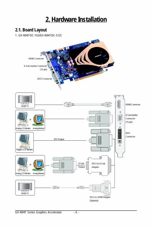
DVI-I Connector
DVI-IConnector
Analog LCD Monitor Analog Monitor
or
Digital LCD Monitor
DVI Output
DVI-I to HDMI Adapter(Optional)
D-SubOutput
HDMI TV
DVI-I to D-SubAdapter
HDMI TV
Analog LCD Monitor Analog Monitor
or
D-Sub monitor Connector(15-pin)
HDMI Connector
HDMI Connector
D-Sub monitorConnector(15-pin)
1. GV-N94TOC-1GI/GV-N94TOC-512I
- 7 - Hardware Installation
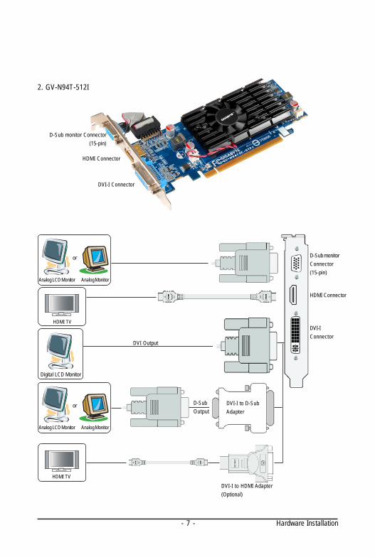
DVI-I Connector
DVI-IConnector
Analog LCD Monitor Analog Monitor
or
Digital LCD Monitor
DVI Output
DVI-I to HDMI Adapter(Optional)
D-SubOutput
HDMI TV
DVI-I to D-SubAdapter
D-Sub monitor Connector(15-pin)
HDMI Connector
HDMI Connector
D-Sub monitorConnector(15-pin)
2. GV-N94T-512I
Analog LCD Monitor Analog Monitor
or
HDMI TV
- 8 -GV-N94T Series Graphics Accelerator
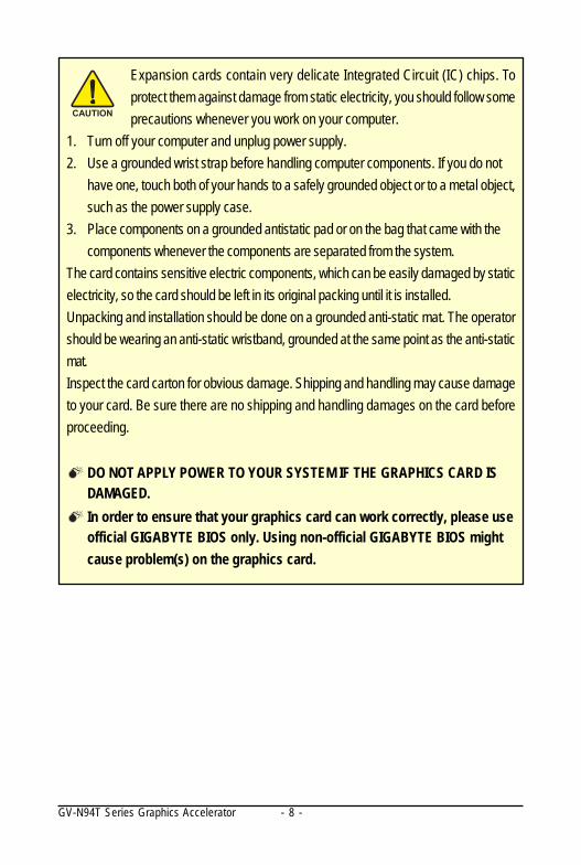
Expansion cards contain very delicate Integrated Circuit (IC) chips. Toprotect them against damage from static electricity, you should follow someprecautions whenever you work on your computer.
1. Turn off your computer and unplug power supply.2. Use a grounded wrist strap before handling computer components. If you do not
have one, touch both of your hands to a safely grounded object or to a metal object,such as the power supply case.
3. Place components on a grounded antistatic pad or on the bag that came with thecomponents whenever the components are separated from the system.
The card contains sensitive electric components, which can be easily damaged by staticelectricity, so the card should be left in its original packing until it is installed.Unpacking and installation should be done on a grounded anti-static mat. The operatorshould be wearing an anti-static wristband, grounded at the same point as the anti-staticmat.Inspect the card carton for obvious damage. Shipping and handling may cause damageto your card. Be sure there are no shipping and handling damages on the card beforeproceeding.
DO NOT APPLY POWER TO YOUR SYSTEM IF THE GRAPHICS CARD ISDAMAGED.In order to ensure that your graphics card can work correctly, please useofficial GIGABYTE BIOS only. Using non-official GIGABYTE BIOS mightcause problem(s) on the graphics card.
- 9 - Hardware Installation
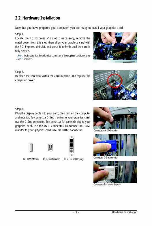
2.2. Hardware Installation
Now that you have prepared your computer, you are ready to install your graphics card.
Step 1.Locate the PCI Express x16 slot. If necessary, remove themetal cover from this slot; then align your graphics card withthe PCI Express x16 slot, and press it in firmly until the card isfully seated.
Step 2.Replace the screw to fasten the card in place, and replace thecomputer cover.
Make sure that the gold edge connector of the graphics card is securelyinserted.
Step 3.Plug the display cable into your card; then turn on the computerand monitor. To connect a D-Sub monitor to your graphics card,use the D-Sub connector. To connect a flat panel display to yourgraphics card, use the DVI-I connector. To connect an HDMImonitor to your graphics card, use the HDMI connector.
Connect a flat panel display
Connect a D-Sub monitor
Connect an HDMI monitor
To Flat Panel DisplayTo D-Sub MonitorTo HDMI Monitor
- 10 -GV-N94T Series Graphics Accelerator
You are now ready to proceed with the installation of the graphics card driver. Please refer to nextchapter for detailed instructions.
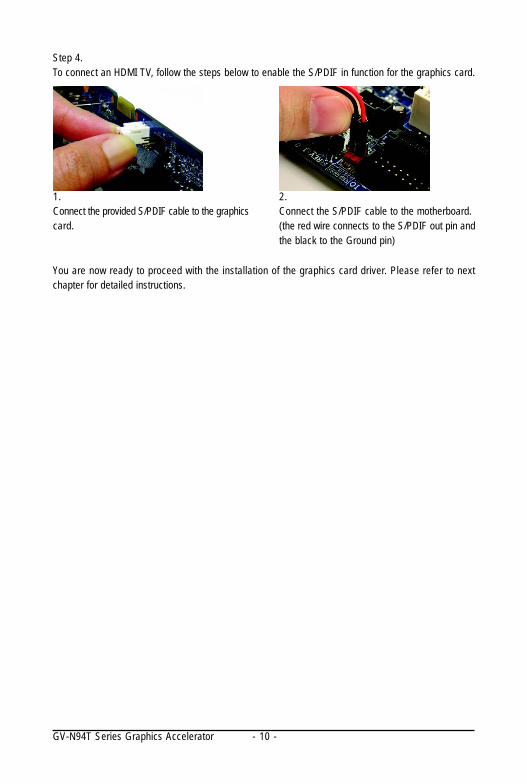
Step 4.To connect an HDMI TV, follow the steps below to enable the S/PDIF in function for the graphics card.
1.Connect the provided S/PDIF cable to the graphicscard.
2.Connect the S/PDIF cable to the motherboard.(the red wire connects to the S/PDIF out pin andthe black to the Ground pin)
- 11 - Software Installation
3. Software InstallationNotice the following guidelines before installing the drivers:
1. First make sure your system has installed DirectX 9 or later version.2. Make sure your system has installed the appropriate motherboard drivers (for the motherboard
drivers, please contact the motherboard manufacturer.)
3.1. Driver and Utility Installation3.1.1. Driver Installation
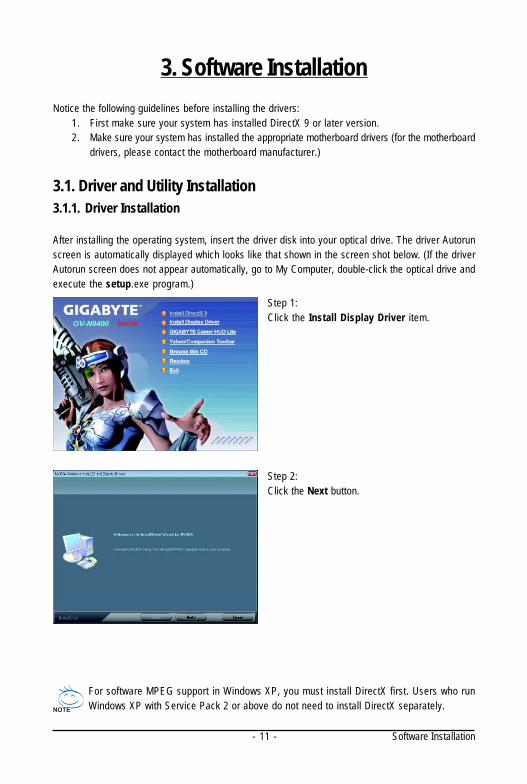
After installing the operating system, insert the driver disk into your optical drive. The driver Autorunscreen is automatically displayed which looks like that shown in the screen shot below. (If the driverAutorun screen does not appear automatically, go to My Computer, double-click the optical drive andexecute the setup.exe program.)
For software MPEG support in Windows XP, you must install DirectX first. Users who runWindows XP with Service Pack 2 or above do not need to install DirectX separately.
Step 1:Click the Install Display Driver item.
Step 2:Click the Next button.
- 12 -GV-N94T Series Graphics Accelerator
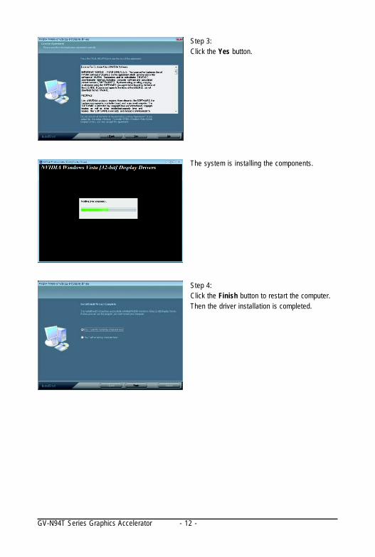
The system is installing the components.
Step 4:Click the Finish button to restart the computer.Then the driver installation is completed.
Step 3:Click the Yes button.
- 13 - Software Installation
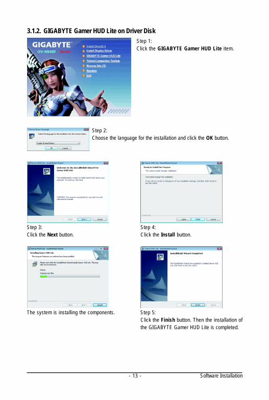
3.1.2. GIGABYTE Gamer HUD Lite on Driver DiskStep 1:Click the GIGABYTE Gamer HUD Lite item.
Step 2:Choose the language for the installation and click the OK button.
Step 3:Click the Next button.
Step 4:Click the Install button.
The system is installing the components. Step 5:Click the Finish button. Then the installation ofthe GIGABYTE Gamer HUD Lite is completed.
- 14 -GV-N94T Series Graphics Accelerator
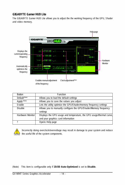
GIGABYTE Gamer HUD LiteThe GIGABYTE Gamer HUD Lite allows you to adjust the the working frequency of the GPU, Shaderand video memory.
Clock adjustment(Note)Enables manual adjustmentof the frequency
Automaticallyoptimizes the
frequency
Displays thecurrent operating
frequencyHardwareMonitor
Help page
(Note) This item is configurable only if 2D/3D Auto-Optimized is set to Disable.
Incorrectly doing overclock/overvoltage may result in damage to your system and reducethe useful life of the system components.
Button FunctionDefault (Note) Allows you to load the default settingsApply (Note) Allows you to save the values you adjustEnable Lets the utility optimize the GPU/Shader/memory frequency settingsDisable Allows you to manually configure the GPU/Shader/Memory frequency
settingsHardware Monitor Displays the GPU usage and temperature, the GPU usage/thermal curve,
and your graphics card information? Opens Help page
- 15 - Software Installation
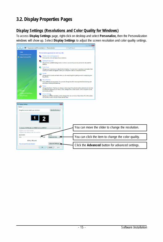
You can move the slider to change the resolution.
You can click the item to change the color quality.
Click the Advanced button for advanced settings.
3.2. Display Properties Pages
Display Settings (Resolutions and Color Quality for Windows)To access Display Settings page, right-click on desktop and select Personalize, then the Personalizationwindows will show up. Select Display Settings to adjust the screen resolution and color quality settings.
- 16 -GV-N94T Series Graphics Accelerator
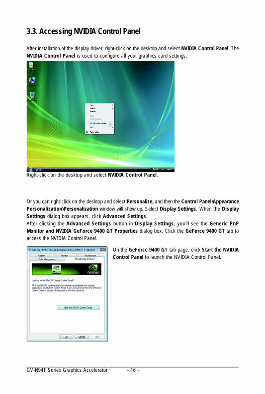
3.3. Accessing NVIDIA Control Panel
After installation of the display driver, right-click on the desktop and select NVIDIA Control Panel. TheNVIDIA Control Panel is used to configure all your graphics card settings.
Right-click on the desktop and select NVIDIA Control Panel.
Or you can right-click on the desktop and select Personalize, and then the Control Panel\AppearancePersonalization\Personalization window will show up. Select Display Settings. When the DisplaySettings dialog box appears, click Advanced Settings.After clicking the Advanced Settings button in Display Settings, you'll see the Generic PnPMonitor and NVIDIA GeForce 9400 GT Properties dialog box. Click the GeForce 9400 GT tab toaccess the NVIDIA Control Panel.
On the GeForce 9400 GT tab page, click Start the NVIDIAControl Panel to launch the NVIDIA Control Panel.
- 17 - Software Installation
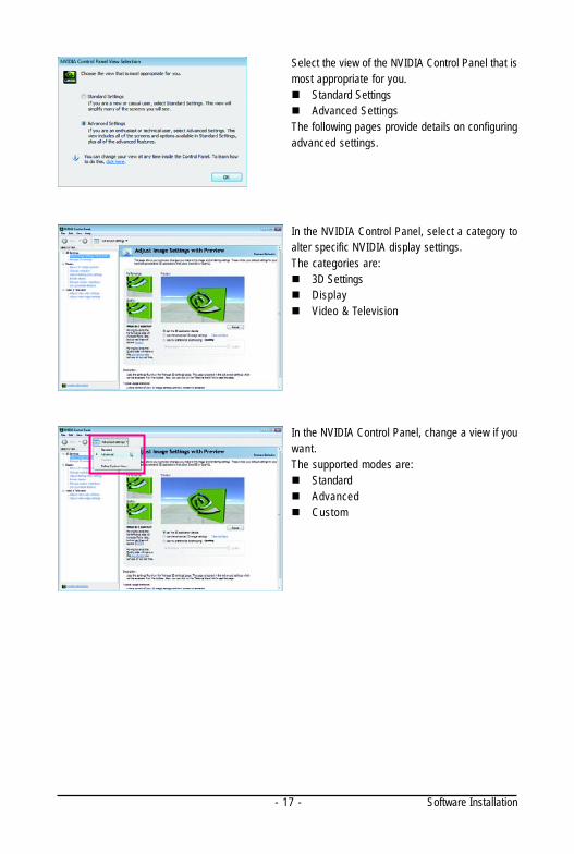
Select the view of the NVIDIA Control Panel that ismost appropriate for you.
Standard SettingsAdvanced Settings
The following pages provide details on configuringadvanced settings.
In the NVIDIA Control Panel, select a category toalter specific NVIDIA display settings.The categories are:
3D SettingsDisplayVideo & Television
In the NVIDIA Control Panel, change a view if youwant.The supported modes are:
StandardAdvancedCustom
- 18 -GV-N94T Series Graphics Accelerator
(Note) This item is present only in Advanced view mode.
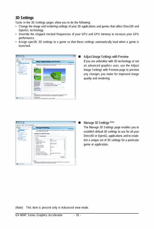
Adjust Image Settings with PreviewIf you are unfamiliar with 3D technology or notan advanced graphics user, use the AdjustImage Settings with Preview page to previewany changes you make for improved imagequality and rendering.
Manage 3D Settings (Note)
The Manage 3D Settings page enables you toestablish default 3D settings to use for all yourDirect3D or OpenGL applications and to estab-lish a unique set of 3D settings for a particulargame or application.
3D SettingsTasks in the 3D Settings pages allow you to do the following:• Change the image and rendering settings of your 3D applications and games that utilize Direct3D and
OpenGL technology.• Override the shipped clocked frequencies of your GPU and GPU memory to increase your GPU
performance.• Assign specific 3D settings to a game so that these settings automatically load when a game is
launched.
- 19 - Software Installation
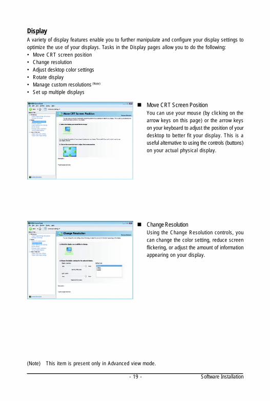
DisplayA variety of display features enable you to further manipulate and configure your display settings tooptimize the use of your displays. Tasks in the Display pages allow you to do the following:• Move CRT screen position• Change resolution• Adjust desktop color settings• Rotate display• Manage custom resolutions (Note)
• Set up multiple displays
(Note) This item is present only in Advanced view mode.
Move CRT Screen PositionYou can use your mouse (by clicking on thearrow keys on this page) or the arrow keyson your keyboard to adjust the position of yourdesktop to better fit your display. This is auseful alternative to using the controls (buttons)on your actual physical display.
Change ResolutionUsing the Change Resolution controls, youcan change the color setting, reduce screenflickering, or adjust the amount of informationappearing on your display.
- 20 -GV-N94T Series Graphics Accelerator
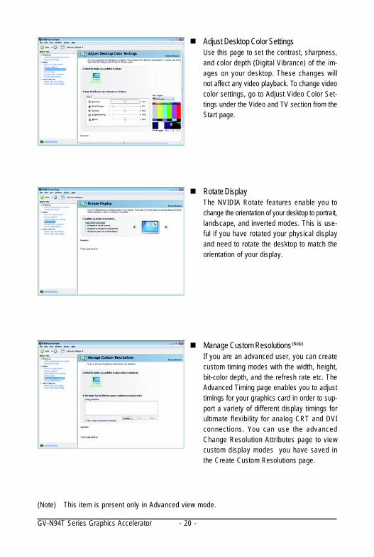
Adjust Desktop Color SettingsUse this page to set the contrast, sharpness,and color depth (Digital Vibrance) of the im-ages on your desktop. These changes willnot affect any video playback. To change videocolor settings, go to Adjust Video Color Set-tings under the Video and TV section from theStart page.
Rotate DisplayThe NVIDIA Rotate features enable you tochange the orientation of your desktop to portrait,landscape, and inverted modes. This is use-ful if you have rotated your physical displayand need to rotate the desktop to match theorientation of your display.
Manage Custom Resolutions (Note)
If you are an advanced user, you can createcustom timing modes with the width, height,bit-color depth, and the refresh rate etc. TheAdvanced Timing page enables you to adjusttimings for your graphics card in order to sup-port a variety of different display timings forultimate flexibility for analog CRT and DVIconnections. You can use the advancedChange Resolution Attributes page to viewcustom display modes you have saved inthe Create Custom Resolutions page.
(Note) This item is present only in Advanced view mode.
- 21 - Software Installation
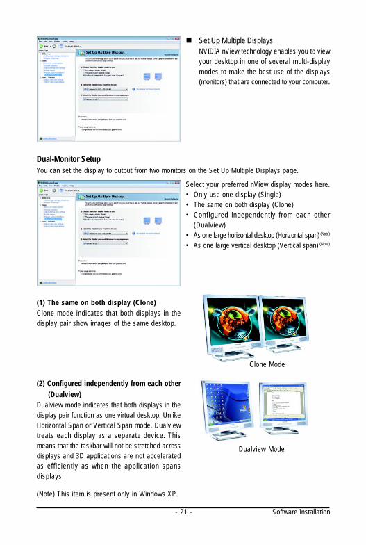
Set Up Multiple DisplaysNVIDIA nView technology enables you to viewyour desktop in one of several multi-displaymodes to make the best use of the displays(monitors) that are connected to your computer.
Dual-Monitor SetupYou can set the display to output from two monitors on the Set Up Multiple Displays page.
Select your preferred nView display modes here.• Only use one display (Single)• The same on both display (Clone)• Configured independently from each other
(Dualview)• As one large horizontal desktop (Horizontal span) (Note)
• As one large vertical desktop (Vertical span) (Note)
(1) The same on both display (Clone)Clone mode indicates that both displays in thedisplay pair show images of the same desktop.
Clone Mode
(Note) This item is present only in Windows XP.
(2) Configured independently from each other (Dualview)Dualview mode indicates that both displays in thedisplay pair function as one virtual desktop. UnlikeHorizontal Span or Vertical Span mode, Dualviewtreats each display as a separate device. Thismeans that the taskbar will not be stretched acrossdisplays and 3D applications are not acceleratedas eff iciently as when the application spansdisplays.
Dualview Mode
- 22 -GV-N94T Series Graphics Accelerator
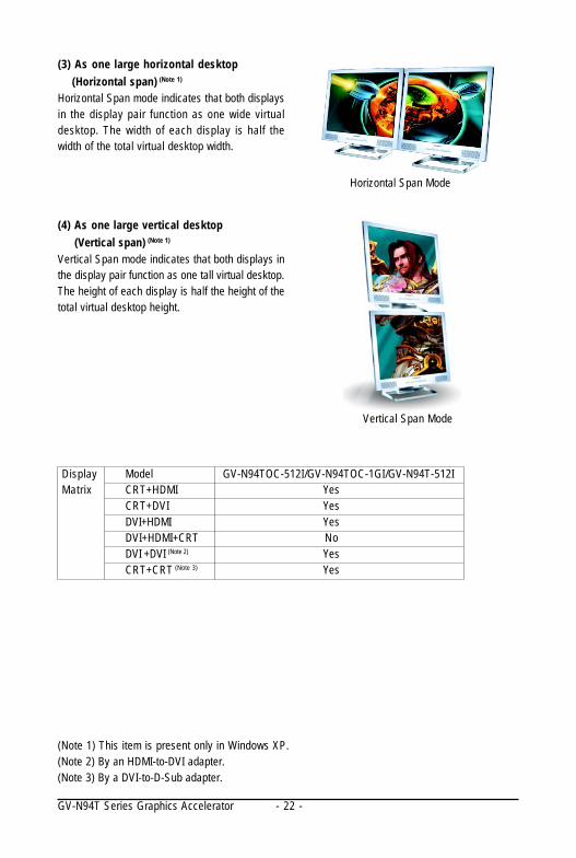
(4) As one large vertical desktop (Vertical span) (Note 1)
Vertical Span mode indicates that both displays inthe display pair function as one tall virtual desktop.The height of each display is half the height of thetotal virtual desktop height.
Vertical Span Mode
(3) As one large horizontal desktop (Horizontal span) (Note 1)
Horizontal Span mode indicates that both displaysin the display pair function as one wide virtualdesktop. The width of each display is half thewidth of the total virtual desktop width.
Horizontal Span Mode
(Note 1) This item is present only in Windows XP.(Note 2) By an HDMI-to-DVI adapter.(Note 3) By a DVI-to-D-Sub adapter.
DisplayMatrix
Model GV-N94TOC-512I/GV-N94TOC-1GI/GV-N94T-512ICRT+HDMI YesCRT+DVI YesDVI+HDMI YesDVI+HDMI+CRT NoDVI +DVI (Note 2) YesCRT+CRT (Note 3) Yes
- 23 - Software Installation
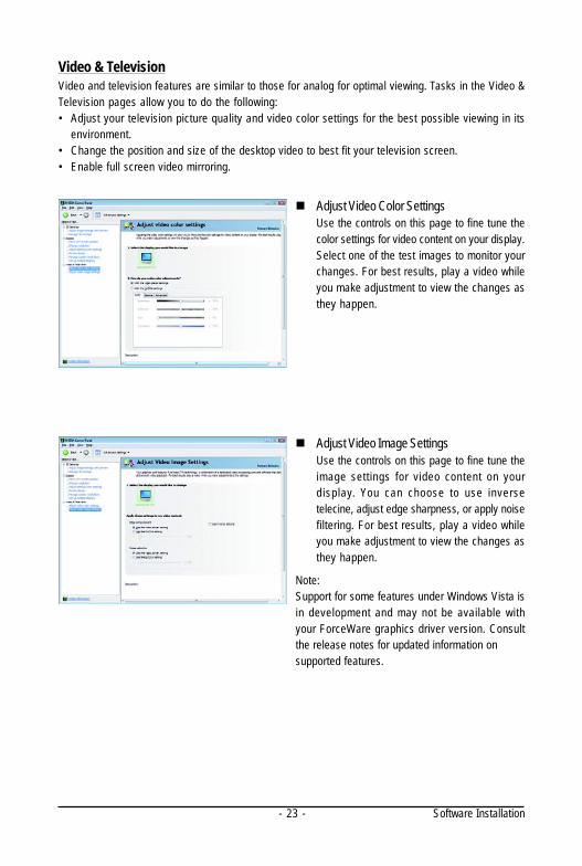
Video & TelevisionVideo and television features are similar to those for analog for optimal viewing. Tasks in the Video &Television pages allow you to do the following:• Adjust your television picture quality and video color settings for the best possible viewing in its
environment.• Change the position and size of the desktop video to best fit your television screen.• Enable full screen video mirroring.
Adjust Video Color SettingsUse the controls on this page to fine tune thecolor settings for video content on your display.Select one of the test images to monitor yourchanges. For best results, play a video whileyou make adjustment to view the changes asthey happen.
Adjust Video Image SettingsUse the controls on this page to fine tune theimage settings for video content on yourdisplay. You can choose to use inversetelecine, adjust edge sharpness, or apply noisefiltering. For best results, play a video whileyou make adjustment to view the changes asthey happen.
Note:Support for some features under Windows Vista isin development and may not be available withyour ForceWare graphics driver version. Consultthe release notes for updated information onsupported features.
- 24 -GV-N94T Series Graphics Accelerator
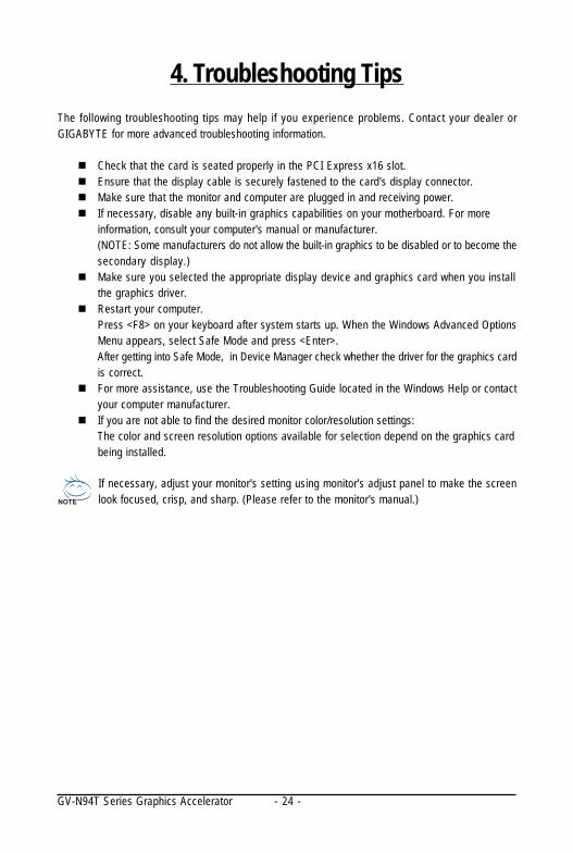
4. Troubleshooting TipsThe following troubleshooting tips may help if you experience problems. Contact your dealer orGIGABYTE for more advanced troubleshooting information.
Check that the card is seated properly in the PCI Express x16 slot.Ensure that the display cable is securely fastened to the card's display connector.Make sure that the monitor and computer are plugged in and receiving power.If necessary, disable any built-in graphics capabilities on your motherboard. For moreinformation, consult your computer's manual or manufacturer.(NOTE: Some manufacturers do not allow the built-in graphics to be disabled or to become thesecondary display.)Make sure you selected the appropriate display device and graphics card when you installthe graphics driver.Restart your computer.Press <F8> on your keyboard after system starts up. When the Windows Advanced OptionsMenu appears, select Safe Mode and press <Enter>.After getting into Safe Mode, in Device Manager check whether the driver for the graphics cardis correct.For more assistance, use the Troubleshooting Guide located in the Windows Help or contactyour computer manufacturer.If you are not able to find the desired monitor color/resolution settings:The color and screen resolution options available for selection depend on the graphics cardbeing installed.
If necessary, adjust your monitor's setting using monitor's adjust panel to make the screenlook focused, crisp, and sharp. (Please refer to the monitor's manual.)
- 25 - Appendix
5. Appendix
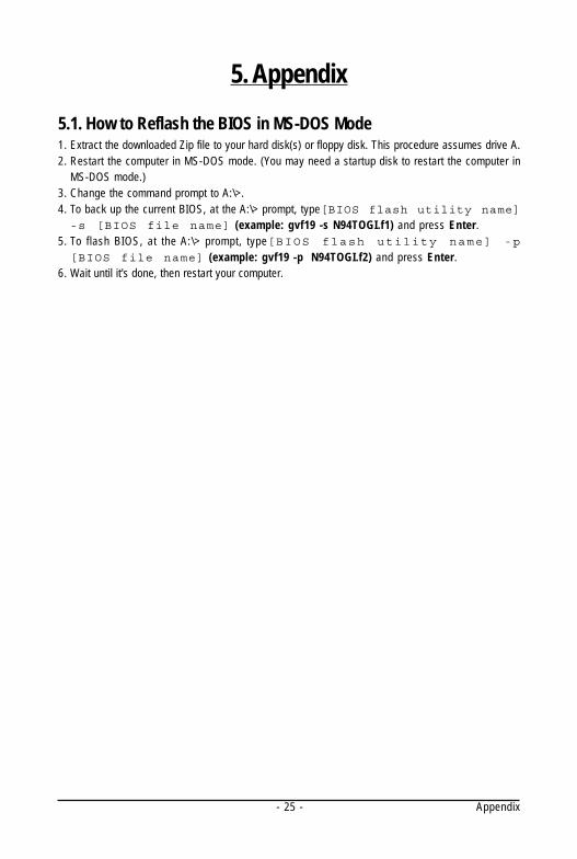
5.1. How to Reflash the BIOS in MS-DOS Mode1. Extract the downloaded Zip file to your hard disk(s) or floppy disk. This procedure assumes drive A.2. Restart the computer in MS-DOS mode. (You may need a startup disk to restart the computer in
MS-DOS mode.)3. Change the command prompt to A:\>.4. To back up the current BIOS, at the A:\> prompt, type[BIOS flash utility name]-s [BIOS file name] (example: gvf19 -s N94TOGI.f1) and press Enter.
5. To flash BIOS, at the A:\> prompt, type[BIOS flash utility name] -p
[BIOS file name] (example: gvf19 -p N94TOGI.f2) and press Enter.6. Wait until it's done, then restart your computer.
- 26 -GV-N94T Series Graphics Accelerator
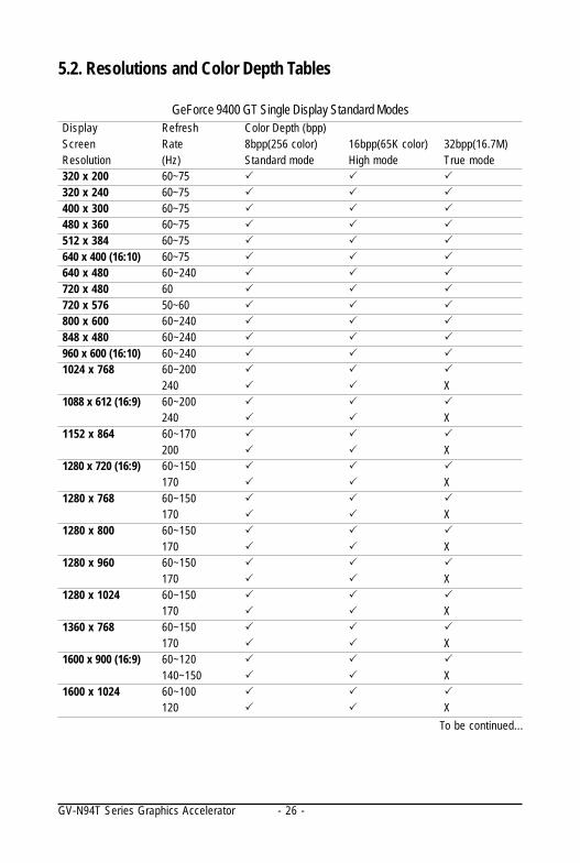
5.2. Resolutions and Color Depth Tables
GeForce 9400 GT Single Display Standard ModesDisplay Refresh Color Depth (bpp)Screen Rate 8bpp(256 color) 16bpp(65K color) 32bpp(16.7M)Resolution (Hz) Standard mode High mode True mode320 x 200 60~75320 x 240 60~75400 x 300 60~75480 x 360 60~75512 x 384 60~75640 x 400 (16:10) 60~75640 x 480 60~240720 x 480 60720 x 576 50~60800 x 600 60~240848 x 480 60~240960 x 600 (16:10) 60~2401024 x 768 60~200
240 X1088 x 612 (16:9) 60~200
240 X1152 x 864 60~170
200 X1280 x 720 (16:9) 60~150
170 X1280 x 768 60~150
170 X1280 x 800 60~150
170 X1280 x 960 60~150
170 X1280 x 1024 60~150
170 X1360 x 768 60~150
170 X1600 x 900 (16:9) 60~120
140~150 X1600 x 1024 60~100
120 XTo be continued...
- 27 - Appendix
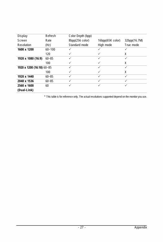
* This table is for reference only. The actual resolutions supported depend on the monitor you use.
Display Refresh Color Depth (bpp)Screen Rate 8bpp(256 color) 16bpp(65K color) 32bpp(16.7M)Resolution (Hz) Standard mode High mode True mode1600 x 1200 60~100
120 X1920 x 1080 (16:9) 60~85
100 X1920 x 1200 (16:10) 60~85
100 X1920 x 1440 60~852048 x 1536 60~852560 x 1600 60(Dual-Link)

- 28 -GV-N94T Series Graphics Accelerator
Regulatory NoticesThis document must not be copied without our written permission, and the contents there of must not beimparted to a third party nor be used for any unauthorized purpose. Contravention will be prosecuted.We believe that the information contained herein was accurate in all respects at the time of printing.GIGABYTE cannot, however, assume any responsibility for errors or omissions in this text. Also notethat the information in this document is subject to change without notice and should not be construed asa commitment by GIGABYTE.
Our Commitment to Preserving the EnvironmentIn addition to high-efficiency performance, all GIGABYTE motherboards fulfill European Union regula-tions for RoHS (Restriction of Certain Hazardous Substances in Electrical and Electronic Equipment)and WEEE (Waste Electrical and Electronic Equipment) environmental directives, as well as mostmajor worldwide safety requirements. To prevent releases of harmful substances into the environmentand to maximize the use of our natural resources, GIGABYTE provides the following information onhow you can responsibly recycle or reuse most of the materials in your "end of life" product.
Restriction of Hazardous Substances (RoHS) Directive StatementGIGABYTE products have not intended to add and safe from hazardous substances (Cd, Pb, Hg, Cr+6,PBDE and PBB). The parts and components have been carefully selected to meet RoHS requirement.Moreover, we at GIGABYTE are continuing our efforts to develop products that do not use internationallybanned toxic chemicals.
Waste Electrical & Electronic Equipment (WEEE) Directive StatementGIGABYTE will fulfill the national laws as interpreted from the 2002/96/EC WEEE (Waste Electrical andElectronic Equipment) directive. The WEEE Directive specifies the treatment, collection, recycling anddisposal of electric and electronic devices and their components. Under the Directive, used equipmentmust be marked, collected separately, and disposed of properly.
WEEE Symbol StatementThe symbol shown below is on the product or on its packaging, which indicates that thisproduct must not be disposed of with other waste. Instead, the device should be taken tothe waste collection centers for activation of the treatment, collection, recycling anddisposal procedure. The separate collection and recycling of your waste equipment at thetime of disposal will help to conserve natural resources and ensure that it is recycled in a
manner that protects human health and the environment. For more information about where you candrop off your waste equipment for recycling, please contact your local government office, yourhousehold waste disposal service or where you purchased the product for details of environmentallysafe recycling.
When your electrical or electronic equipment is no longer useful to you, "take it back" to your localor regional waste collection administration for recycling.If you need further assistance in recycling, reusing in your "end of life" product, you may contact usat the Customer Care number listed in your product's user's manual and we will be glad to help youwith your effort.
5.3. Regulatory Statements
- 29 - Appendix
Finally, we suggest that you practice other environmentally friendly actions by understanding andusing the energy-saving features of this product (where applicable), recycling the inner and outerpackaging (including shipping containers) this product was delivered in, and by disposing of orrecycling used batteries properly. With your help, we can reduce the amount of natural resourcesneeded to produce electrical and electronic equipment, minimize the use of landfills for the disposal of"end of life" products, and generally improve our quality of life by ensuring that potentially hazardoussubstances are not released into the environment and are disposed of properly.
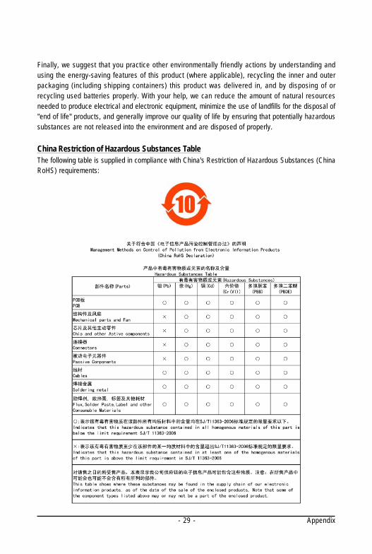
China Restriction of Hazardous Substances TableThe following table is supplied in compliance with China's Restriction of Hazardous Substances (ChinaRoHS) requirements:

- 30 -GV-N94T Series Graphics Accelerator