Embed Size (px)
Citation preview
Overhead Electric Distribution Standards
Revised: January 1, 2018 Revised By: HTH Approved By: BTM
GUYS & ANCHORS V. 2. - Page 1 of 34
GUYS AND ANCHORS I. DESIGN
The guying systems and specifications in this section have been designed according to the requirements set forth in the National Electrical Safety Code (NESC) (1993 Edition). Section 26 of the NESC gives the details to be considered when designing guying systems. The factors included in the design are:
A. CONDUCTOR TENSIONS (MAXIMUM)
B. SHIELD AND NEUTRAL TENSIONS (MAXIMUM)
C. WIND LOADING
D. COLUMNAR LOADING OF POLE (MAXIMUM BOWING MOMENT)
E. NESC GRADE B CONSTRUCTION (SEE NOTE BELOW)
F. NESC OVERLOAD CAPACITY FACTORS (TABLE 264-1)
Note: JEA designs all Overhead Electric Facilities to NESC Grade B construction even when a lower grade may be allowable by Code.
II. GROUNDING
JEA design criterion requires that all downguys be grounded whether they contain insulators or not. This grounding is accomplished by installing a #4 CU jumper between the guy strand and the pole ground. This connection would be below the lowest guy insulator if one or more are installed in the guy strand. Section 215C2 of the NESC allows for some exceptions in this area that the JEA chooses not to allow.
III. MATERIAL AND USES
A. GUY STRAND
JEA uses two sizes of guy strand to accomplish all distribution guying requirements. They are 3/8” and 7/16” in diameter and are made of galvanized steel and conform to ASTM specification A475-72. The minimum breaking strengths are 11,500 pounds and 20,800 pounds respectively.
B. STRAIN INSULATORS
Strain insulators come in two lengths, 60” and 144”. They are to be used in downguys and spanguys that are in close proximity to energized conductor or equipment on the pole. The purpose for these is so that if a guy system failed and the guy strand fell against energized conductor, the guy strand itself would not become energized. The 144” insulator is normally used in the A and B phase positions, with the 60” normally used at the C phase position. The 144” insulator is also used on poles where the conductor size changes (i.e., 636 KCM aluminum deadends vertically and 1/0 aluminum conductor continues on) and on deadend poles with equipment (i.e., transformers, risers, etc.). Strain insulators (guy breakers) shall not touch primary conductors or insulators.
Overhead Electric Distribution Standards
Revised: January 1, 2018 Revised By: HTH Approved By: BTM
GUYS AND ANCHORS V. 2. - Page 2 of 34
C. BOLTS
Guy plates are provided with bolts for each plate, but may not be needed if already supplied with another plate. Bolts are provided to attach to a standard 50 foot, class 2 wood pole for normal construction. If a downguy is installed on a larger pole, a bolt plate will need to plated if available.
D. GUY ATTACHMENTS
The guy strand is attached to the pole by use of one of two different pole attachment plates. These plates are stackable at one location on the pole to allow for installing two downguys at one point on the pole (i.e., 636 KCM aluminum deadended on crossarms requires two 7/16” downguys at bolt hole 73) - See plate GY7SPL. Provisions for downguys are also provided on the steel crossarm and the 3-phase cutout and arrester bracket if required.
E. GUY ANCHORS
Two basic types of anchoring systems are used for downguys -- one is the screw type and the other is the “Manta-Ray” type. The screw anchors come in two different styles, a single-helix and a multi or double-helix. The single-helix anchor is 8 feet long with a 10” diameter screw. The multi-helix anchor is 5 feet long and comes with a 10” and 11.3” diameter screws. The “Manta-Ray” anchoring system is a patented system that allows for the installation of a high-strength anchor in areas not accessible to large trucks or equipment. The “Manta-Ray” holding strength is equivalent to that of the multi-helix anchor. Holding strengths for guy anchors are very dependent on the type of soil conditions in which the anchor is placed. Below is a table to quantify typical holding strengths for anchors.
TABLE 1: ANCHOR HOLDING STRENGTH
Anchor Type Holding Strength
Poor Soil Good Soil
Single-Helix 6,000 pounds 10,000 pounds
Multi-Helix *18,000 pounds *18,000 pounds
Manta-Ray >15,000 pounds >15,000 pounds
Poor soil includes: Loose sand, wet clay, loam and marsh lands. Good soil includes: Compacted clay and gravel, hardpan, claypan, and compacted sand.
Depends on obtaining one (1) full twist in the anchor rod upon installation.
F. SECONDARY GUYS
These guidelines are for the normal construction practices. For secondary attachments at higher than normal levels, guy leads would need to be adjusted accordingly.
III.F.1. For #2 Triplex or Quadraplex and 1/0 Triplex secondary busses between distribution line poles, a “GY3” with a 12 foot guy lead is required.
III.F.2. For 2/0 or 4/0 PAP or Quadraplex secondary busses between distribution line poles, a “GY3” with a 15 foot guy lead is required.
III.F.3. If a downguy is required for a secondary drop form a distribution line pole to the customer, a “GY3” with a 10 foot guy lead would be adequate.
III.F.4. For #6 Duplex busses or drops, the Engineer will decide on a case to case basis if any guying is required.
Overhead Electric Distribution Standards
Revised: January 1, 2018 Revised By: HTH Approved By: BTM
GUYS & ANCHORS V. 2. - Page 3 of 34
G. SIDEWALK GUYS
These utilize 3/8” guy strand only and are to be used only when a normal guy lead cannot be obtained. This type of downguy exerts a very large moment on the pole in the area of the stand-off pipe, often exceeding the minimum bowing moment for the pole if used in heavy strain situations. The limitations of the guy strand and all the components of the guy system are usually exceeded if used on more than single-phase primary or secondary drop installations. It may be necessary to install a strain pole if conditions exceed the above.
H. POLE KEYS
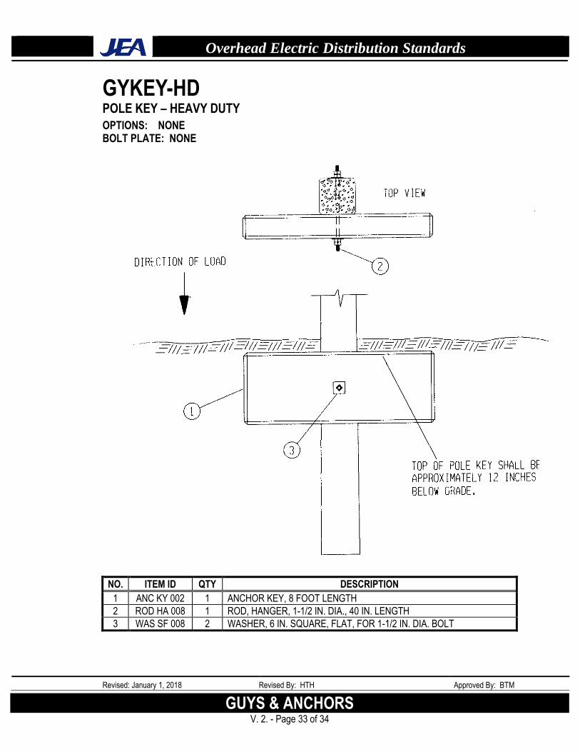
These are for use on concrete poles where a conventional downguy and anchor cannot be installed. They are for loose soil conditions and should only be used as a last resort method for resisting light strains. The heavy duty key is for use on LT class and larger poles. The light duty key is for class 3 and class H poles.
Before requesting that a pole key be installed, please review the design with your supervisor.
I. BOG SHOES
These are for poles being set in “Muck” areas. Their use is limited and is usually reserved for smaller wire installations. It is much more preferable to increase the setting depth of the pole to reach a more stable layer than to utilize bog shoes. When these type areas are encountered it may be necessary to obtain a soil boring to determine the required setting depth.
Before requesting that a bog shoe be installed, please review the design with your supervisor.
J. POLE BRACES
These are used to secure a pole that may be undermined by an excavation operation. They shall always be installed perpendicular to the overhead wires. The heavy duty brace is for three-phase lines and larger poles. The light duty brace is for single and two-phase lines and smaller poles or poles being partially exposed. The use of these braces is not an exact science. There are many factors to be considered when evaluating a construction site and making a determination as to what method of pole support to use. NEVER GUESS!!!. Always know that the method chosen will accomplish the task required.
K. BUTT GUYS
These guys have very little application and should be only used if you are well experienced in their use. The heavy duty butt guy is mainly used for soft earth areas where pole settlement is a possibility. The light duty butt guy is for use where very little of the pole is to be exposed and where at least three (3) feet of the pole butt is in solid ground not to be disturbed. As with pole braces, always know that the method chosen will accomplish the task.
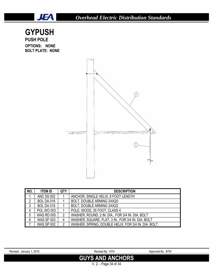
L. PUSH POLES
The basic use of this type installation is where a downguy has to be temporarily removed. This should not be considered a permanent installation. Push poles do have limitations. If you have any questions at all about their ability to accomplish the task, consult your supervisor.
Overhead Electric Distribution Standards
Revised: January 1, 2018 Revised By: HTH Approved By: BTM
GUYS AND ANCHORS V. 2. - Page 4 of 34
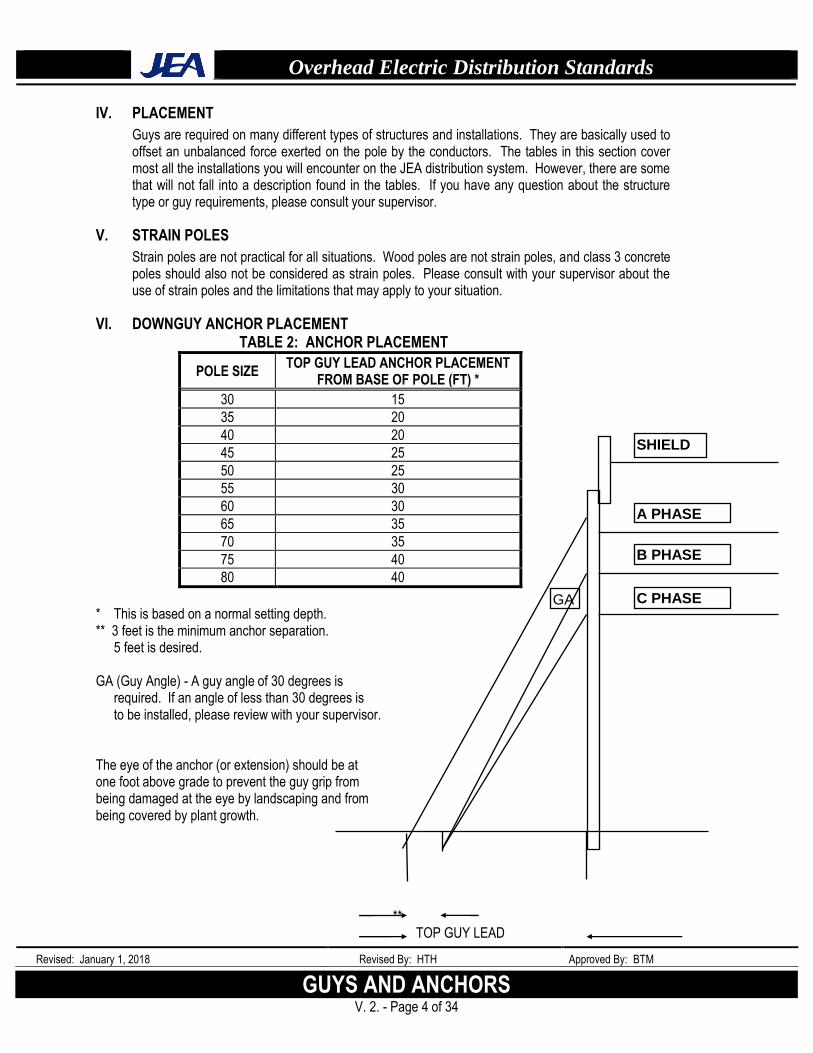
IV. PLACEMENT
Guys are required on many different types of structures and installations. They are basically used to offset an unbalanced force exerted on the pole by the conductors. The tables in this section cover most all the installations you will encounter on the JEA distribution system. However, there are some that will not fall into a description found in the tables. If you have any question about the structure type or guy requirements, please consult your supervisor.
V. STRAIN POLES
Strain poles are not practical for all situations. Wood poles are not strain poles, and class 3 concrete poles should also not be considered as strain poles. Please consult with your supervisor about the use of strain poles and the limitations that may apply to your situation.
VI. DOWNGUY ANCHOR PLACEMENT TABLE 2: ANCHOR PLACEMENT
POLE SIZE TOP GUY LEAD ANCHOR PLACEMENT
FROM BASE OF POLE (FT) *
30 15
35 20
40 20
45 25
50 25
55 30
60 30
65 35
70 35
75 40
80 40
* This is based on a normal setting depth. ** 3 feet is the minimum anchor separation.
5 feet is desired. GA (Guy Angle) - A guy angle of 30 degrees is
required. If an angle of less than 30 degrees is to be installed, please review with your supervisor.
The eye of the anchor (or extension) should be at one foot above grade to prevent the guy grip from being damaged at the eye by landscaping and from being covered by plant growth. ** TOP GUY LEAD
SHIELD
A PHASE
B PHASE
C PHASE GA
Overhead Electric Distribution Standards
Revised: January 1, 2018 Revised By: HTH Approved By: BTM
GUYS & ANCHORS V. 2. - Page 5 of 34
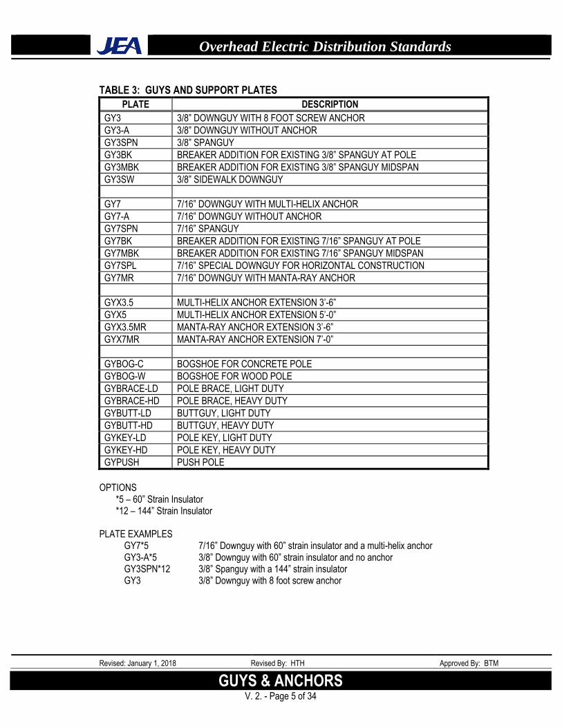
TABLE 3: GUYS AND SUPPORT PLATES
PLATE DESCRIPTION
GY3 3/8” DOWNGUY WITH 8 FOOT SCREW ANCHOR
GY3-A 3/8” DOWNGUY WITHOUT ANCHOR
GY3SPN 3/8” SPANGUY
GY3BK BREAKER ADDITION FOR EXISTING 3/8” SPANGUY AT POLE
GY3MBK BREAKER ADDITION FOR EXISTING 3/8” SPANGUY MIDSPAN
GY3SW 3/8” SIDEWALK DOWNGUY
GY7 7/16” DOWNGUY WITH MULTI-HELIX ANCHOR
GY7-A 7/16” DOWNGUY WITHOUT ANCHOR
GY7SPN 7/16” SPANGUY
GY7BK BREAKER ADDITION FOR EXISTING 7/16” SPANGUY AT POLE
GY7MBK BREAKER ADDITION FOR EXISTING 7/16” SPANGUY MIDSPAN
GY7SPL 7/16” SPECIAL DOWNGUY FOR HORIZONTAL CONSTRUCTION
GY7MR 7/16” DOWNGUY WITH MANTA-RAY ANCHOR
GYX3.5 MULTI-HELIX ANCHOR EXTENSION 3’-6”
GYX5 MULTI-HELIX ANCHOR EXTENSION 5’-0”
GYX3.5MR MANTA-RAY ANCHOR EXTENSION 3’-6”
GYX7MR MANTA-RAY ANCHOR EXTENSION 7’-0”
GYBOG-C BOGSHOE FOR CONCRETE POLE
GYBOG-W BOGSHOE FOR WOOD POLE
GYBRACE-LD POLE BRACE, LIGHT DUTY
GYBRACE-HD POLE BRACE, HEAVY DUTY
GYBUTT-LD BUTTGUY, LIGHT DUTY
GYBUTT-HD BUTTGUY, HEAVY DUTY
GYKEY-LD POLE KEY, LIGHT DUTY
GYKEY-HD POLE KEY, HEAVY DUTY
GYPUSH PUSH POLE
OPTIONS
*5 – 60” Strain Insulator *12 – 144” Strain Insulator
PLATE EXAMPLES
GY7*5 7/16” Downguy with 60” strain insulator and a multi-helix anchor GY3-A*5 3/8” Downguy with 60” strain insulator and no anchor GY3SPN*12 3/8” Spanguy with a 144” strain insulator GY3 3/8” Downguy with 8 foot screw anchor
Overhead Electric Distribution Standards
Revised: January 1, 2018 Revised By: HTH Approved By: BTM
GUYS AND ANCHORS V. 2. - Page 6 of 34
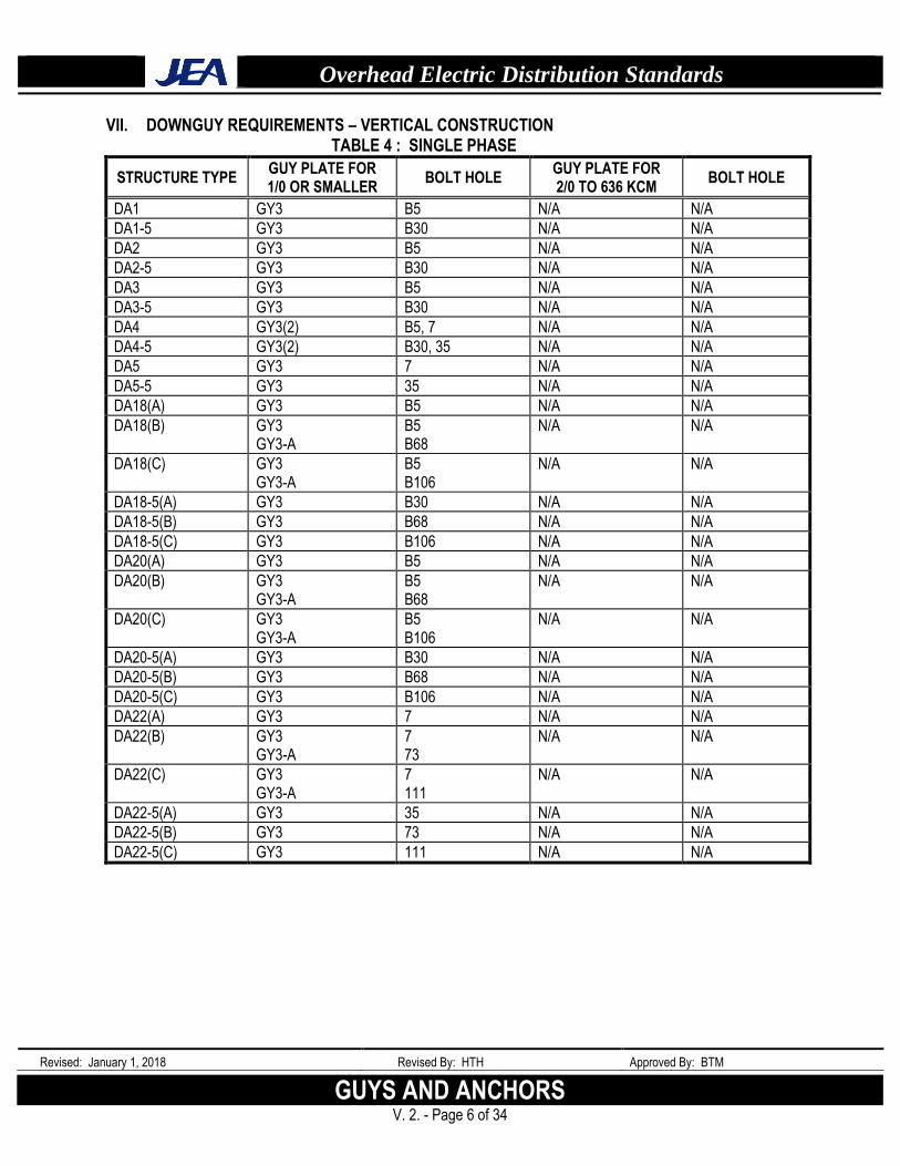
VII. DOWNGUY REQUIREMENTS – VERTICAL CONSTRUCTION TABLE 4 : SINGLE PHASE
STRUCTURE TYPE GUY PLATE FOR 1/0 OR SMALLER
BOLT HOLE GUY PLATE FOR 2/0 TO 636 KCM
BOLT HOLE
DA1 GY3 B5 N/A N/A
DA1-5 GY3 B30 N/A N/A
DA2 GY3 B5 N/A N/A
DA2-5 GY3 B30 N/A N/A
DA3 GY3 B5 N/A N/A
DA3-5 GY3 B30 N/A N/A
DA4 GY3(2) B5, 7 N/A N/A
DA4-5 GY3(2) B30, 35 N/A N/A
DA5 GY3 7 N/A N/A
DA5-5 GY3 35 N/A N/A
DA18(A) GY3 B5 N/A N/A
DA18(B) GY3 GY3-A
B5 B68
N/A N/A
DA18(C) GY3 GY3-A
B5 B106
N/A N/A
DA18-5(A) GY3 B30 N/A N/A
DA18-5(B) GY3 B68 N/A N/A
DA18-5(C) GY3 B106 N/A N/A
DA20(A) GY3 B5 N/A N/A
DA20(B) GY3 GY3-A
B5 B68
N/A N/A
DA20(C) GY3 GY3-A
B5 B106
N/A N/A
DA20-5(A) GY3 B30 N/A N/A
DA20-5(B) GY3 B68 N/A N/A
DA20-5(C) GY3 B106 N/A N/A
DA22(A) GY3 7 N/A N/A
DA22(B) GY3 GY3-A
7 73
N/A N/A
DA22(C) GY3 GY3-A
7 111
N/A N/A
DA22-5(A) GY3 35 N/A N/A
DA22-5(B) GY3 73 N/A N/A
DA22-5(C) GY3 111 N/A N/A
Overhead Electric Distribution Standards
Revised: January 1, 2018 Revised By: HTH Approved By: BTM
GUYS & ANCHORS V. 2. - Page 7 of 34
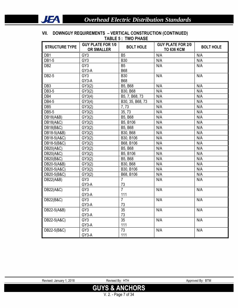
VII. DOWNGUY REQUIREMENTS – VERTICAL CONSTRUCTION (CONTINUED) TABLE 5 : TWO PHASE
STRUCTURE TYPE GUY PLATE FOR 1/0
OR SMALLER BOLT HOLE
GUY PLATE FOR 2/0 TO 636 KCM
BOLT HOLE
DB1 GY3 B5 N/A N/A
DB1-5 GY3 B30 N/A N/A
DB2 GY3 GY3-A
B5 B68
N/A N/A
DB2-5 GY3 GY3-A
B30 B68
N/A N/A
DB3 GY3(2) B5, B68 N/A N/A
DB3-5 GY3(2) B30, B68 N/A N/A
DB4 GY3(4) B5, 7, B68, 73 N/A N/A
DB4-5 GY3(4) B30, 35, B68, 73 N/A N/A
DB5 GY3(2) 7, 73 N/A N/A
DB5-5 GY3(2) 35, 73 N/A N/A
DB18(A&B) GY3(2) B5, B68 N/A N/A
DB18(A&C) GY3(2) B5, B106 N/A N/A
DB18(B&C) GY3(2) B5, B68 N/A N/A
DB18-5(A&B) GY3(2) B30, B68 N/A N/A
DB18-5(A&C) GY3(2) B30, B106 N/A N/A
DB18-5(B&C) GY3(2) B68, B106 N/A N/A
DB20(A&C) GY3(2) B5, B68 N/A N/A
DB20(A&C) GY3(2) B5, B106 N/A N/A
DB20(B&C) GY3(2) B5, B68 N/A N/A
DB20-5(A&B) GY3(2) B30, B68 N/A N/A
DB20-5(A&C) GY3(2) B30, B106 N/A N/A
DB20-5(B&C) GY3(2) B68, B106 N/A N/A
DB22(A&B) GY3 GY3-A
7 73
N/A N/A
DB22(A&C) GY3 GY3-A
7 111
N/A N/A
DB22(B&C) GY3 GY3-A
7 73
N/A N/A
DB22-5(A&B) GY3 GY3-A
35 73
N/A N/A
DB22-5(A&C) GY3 GY3-A
35 111
N/A N/A
DB22-5(B&C) GY3 GY3-A
73 111
N/A N/A
Overhead Electric Distribution Standards
Revised: January 1, 2018 Revised By: HTH Approved By: BTM
GUYS AND ANCHORS V. 2. - Page 8 of 34
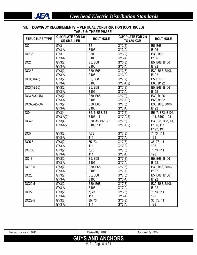
VII. DOWNGUY REQUIREMENTS – VERTICAL CONSTRUCTION (CONTINUED) TABLE 6: THREE PHASE
STRUCTURE TYPE GUY PLATE FOR 1/0
OR SMALLER BOLT HOLE
GUY PLATE FOR 2/0 TO 636 KCM
BOLT HOLE
DC1 GY3 GY3-A
B5 B106
GY3(2) GY3-A
B5, B68 B106
DC1-5 GY3 GY3-A
B30 B106
GY3(2) GY3-A
B30, B68 B106
DC2 GY3(2) GY3-A
B5, B68 B106
GY3(3) GY3-A
B5, B68, B106 B192
DC2-5 GY3(2) GY3-A
B30, B68 B106
GY3(3) GY3-A
B30, B68, B106 B192
DC3(30-45) GY3(2) GY3-A
B5, B68 B106
GY7(2) GY7-A(2)
B5, B106 B68, B192
DC3(45-60) GY3(2) GY3-A
B5, B68 B106
GY7(3) GY7-A
B5, B68, B106 B192
DC3-5(30-45) GY3(2) GY3-A
B30, B68 B106
GY7(2) GY7-A(2)
B30, B106 B68, B192
DC3-5(45-60) GY3(2) GY3-A
B30, B68 B106
GY7(3) GY7-A
B30, B68, B106 B192
DC4 GY3(4) GY3-A(2)
B5, 7, B68, 73 B106, 111
GY7(6) GY7-A(2)
B5, 7, B73, B106, 111, B192, 198
DC4-5 GY3(4) GY3-A(2)
B30, 35, B68, 73 B106, 111
GY7(6) GY7-A(2)
B30, 35, B68, 73, B106, 111 B192, 198
DC5 GY3(2) GY3-A
7,73 111
GY7(3) GY7-A
7, 73, 111 198
DC5-5 GY3(2) GY3-A
35, 73 111
GY7(3) GY7-A
35, 73, 111 198
DC7SL GY3(2) GY3-A
7,73 111
GY7(3) GY7-A
7, 73, 111 198
DC18 GY3(2) GY3-A
B5, B68 B106
GY7(3) GY7-A
B5, B68, B106 B192
DC18-5 GY3(2) GY3-A
B30, B68 B106
GY7(3) GY7-A
B30, B68, B106 B192
DC20 GY3(2) GY3-A
B5, B68 B106
GY7(3) GY7-A
B5, B68, B106 B192
DC20-5 GY3(2) GY3-A
B30, B68 B106
GY7(3) GY7-A
B30, B68, B106 B192
DC22 GY3(2) GY3-A
7, 73 111
GY3(3) GY3-A
7, 73, 111 198
DC22-5 GY3(2) GY3-A
35, 73 111
GY3(3) GY3-A
35, 73, 111 198
Overhead Electric Distribution Standards
Revised: January 1, 2018 Revised By: HTH Approved By: BTM
GUYS & ANCHORS V. 2. - Page 9 of 34
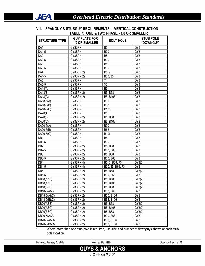
VIII. SPANGUY & STUBGUY REQUIREMENTS – VERTICAL CONSTRUCTION TABLE 7: ONE & TWO PHASE - 1/0 OR SMALLER
STRUCTURE TYPE GUY PLATE FOR 1/0 OR SMALLER
BOLT HOLE STUB POLE *DOWNGUY
DA1 GY3SPN B5 GY3
DA1-5 GY3SPN B30 GY3
DA2 GY3SPN B5 GY3
DA2-5 GY3SPN B30 GY3
DA3 GY3SPN B5 GY3
DA3-5 GY3SPN B30 GY3
DA4 GY3SPN(2) B5, 7 GY3
DA4-5 GY3SPN(2) B30, 35 GY3
DA5 GY3SPN 7 GY3
DA5-5 GY3SPN 35 GY3
DA18(A) GY3SPN B5 GY3
DA18(B) GY3SPN(2) B5, B68 GY3
DA18(C) GY3SPN(2) B5, B106 GY3
DA18-5(A) GY3SPN B30 GY3
DA18-5(B) GY3SPN B68 GY3
DA18-5(C) GY3SPN B106 GY3
DA20(A) GY3SPN B5 GY3
DA20(B) GY3SPN(2) B5, B68 GY3
DA20(C) GY3SPN(2) B5, B106 GY3
DA20-5(A) GY3SPN B30 GY3
DA20-5(B) GY3SPN B68 GY3
DA20-5(C) GY3SPN B106 GY3
DB1 GY3SPN B5 GY3
DB1-5 GY3SPN B30 GY3
DB2 GY3SPN(2) B5, B68 GY3
DB2-5 GY3SPN(2) B30, B68 GY3
DB3 GY3SPN(2) B5, B68 GY3
DB3-5 GY3SPN(2) B30, B68 GY3
DB4 GY3SPN(4) B5, 7, B68, 73 GY3(2)
DB4-5 GY3SPN(4) B30, 35, B68, 73 GY3
DB5 GY3SPN(2) B5, B68 GY3(2)
DB5-5 GY3SPN(2) B30, B68 GY3
DB18(A&B) GY3SPN(2) B5, B68 GY3(2)
DB18(A&C) GY3SPN(2) B5. B106 GY3(2)
DB18(B&C) GY3SPN(2) B5, B68 GY3(2)
DB18-5(A&B) GY3SPN(2) B30, B68 GY3
DB18-5(A&C) GY3SPN(2) B30, B106 GY3
DB18-5(B&C) GY3SPN(2) B68, B106 GY3
DB20(A&B) GY3SPN(2) B5, B68 GY3(2)
DB20(A&C) GY3SPN(2) B5, B106 GY3(2)
DB20(B&C) GY3SPN(2) B5, B68 GY3(2)
DB20-5(A&B) GY3SPN(2) B30, B68 GY3
DB20-5(A&C) GY3SPN(2) B30, B106 GY3
DB20-5(B&C) GY3SPN(2) B68, B106 GY3
* Where more than one stub pole is required, use size and number of downguys shown at each stub pole location.
Overhead Electric Distribution Standards
Revised: January 1, 2018 Revised By: HTH Approved By: BTM
GUYS AND ANCHORS V. 2. - Page 10 of 34
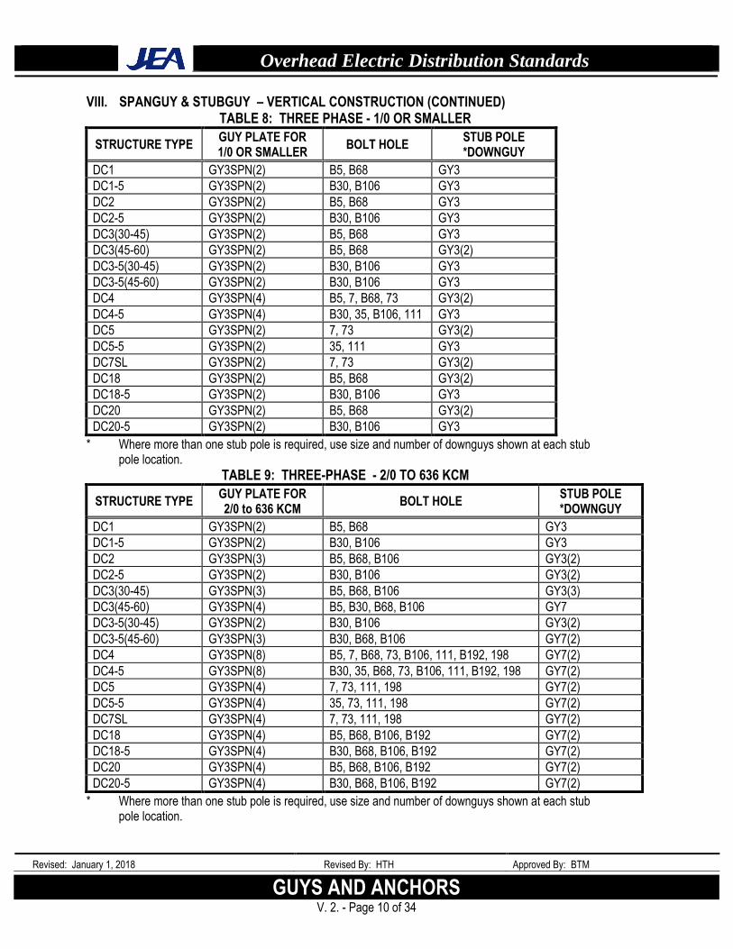
VIII. SPANGUY & STUBGUY – VERTICAL CONSTRUCTION (CONTINUED) TABLE 8: THREE PHASE - 1/0 OR SMALLER
STRUCTURE TYPE GUY PLATE FOR 1/0 OR SMALLER
BOLT HOLE STUB POLE *DOWNGUY
DC1 GY3SPN(2) B5, B68 GY3
DC1-5 GY3SPN(2) B30, B106 GY3
DC2 GY3SPN(2) B5, B68 GY3
DC2-5 GY3SPN(2) B30, B106 GY3
DC3(30-45) GY3SPN(2) B5, B68 GY3
DC3(45-60) GY3SPN(2) B5, B68 GY3(2)
DC3-5(30-45) GY3SPN(2) B30, B106 GY3
DC3-5(45-60) GY3SPN(2) B30, B106 GY3
DC4 GY3SPN(4) B5, 7, B68, 73 GY3(2)
DC4-5 GY3SPN(4) B30, 35, B106, 111 GY3
DC5 GY3SPN(2) 7, 73 GY3(2)
DC5-5 GY3SPN(2) 35, 111 GY3
DC7SL GY3SPN(2) 7, 73 GY3(2)
DC18 GY3SPN(2) B5, B68 GY3(2)
DC18-5 GY3SPN(2) B30, B106 GY3
DC20 GY3SPN(2) B5, B68 GY3(2)
DC20-5 GY3SPN(2) B30, B106 GY3
* Where more than one stub pole is required, use size and number of downguys shown at each stub pole location.
TABLE 9: THREE-PHASE - 2/0 TO 636 KCM
STRUCTURE TYPE GUY PLATE FOR 2/0 to 636 KCM
BOLT HOLE STUB POLE *DOWNGUY
DC1 GY3SPN(2) B5, B68 GY3
DC1-5 GY3SPN(2) B30, B106 GY3
DC2 GY3SPN(3) B5, B68, B106 GY3(2)
DC2-5 GY3SPN(2) B30, B106 GY3(2)
DC3(30-45) GY3SPN(3) B5, B68, B106 GY3(3)
DC3(45-60) GY3SPN(4) B5, B30, B68, B106 GY7
DC3-5(30-45) GY3SPN(2) B30, B106 GY3(2)
DC3-5(45-60) GY3SPN(3) B30, B68, B106 GY7(2)
DC4 GY3SPN(8) B5, 7, B68, 73, B106, 111, B192, 198 GY7(2)
DC4-5 GY3SPN(8) B30, 35, B68, 73, B106, 111, B192, 198 GY7(2)
DC5 GY3SPN(4) 7, 73, 111, 198 GY7(2)
DC5-5 GY3SPN(4) 35, 73, 111, 198 GY7(2)
DC7SL GY3SPN(4) 7, 73, 111, 198 GY7(2)
DC18 GY3SPN(4) B5, B68, B106, B192 GY7(2)
DC18-5 GY3SPN(4) B30, B68, B106, B192 GY7(2)
DC20 GY3SPN(4) B5, B68, B106, B192 GY7(2)
DC20-5 GY3SPN(4) B30, B68, B106, B192 GY7(2)
* Where more than one stub pole is required, use size and number of downguys shown at each stub pole location.
Overhead Electric Distribution Standards
Revised: January 1, 2018 Revised By: HTH Approved By: BTM
GUYS & ANCHORS V. 2. - Page 11 of 34
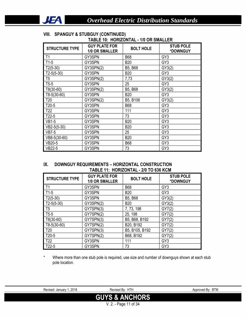
VIII. SPANGUY & STUBGUY (CONTINUED) TABLE 10: HORIZONTAL - 1/0 OR SMALLER
STRUCTURE TYPE GUY PLATE FOR 1/0 OR SMALLER
BOLT HOLE STUB POLE *DOWNGUY
T1 GY3SPN B68 GY3
T1-5 GY3SPN B20 GY3
T2(5-30) GY3SPN(2) B5, B68 GY3(2)
T2-5(5-30) GY3SPN B20 GY3
T5 GY3SPN(2) 7,73 GY3(2)
T5-5 GY3SPN 25 GY3
T8(30-60) GY3SPN(2) B5, B68 GY3(2)
T8-5(30-60) GY3SPN B20 GY3
T20 GY3SPN(2) B5, B106 GY3(2)
T20-5 GY3SPN B68 GY3
T22 GY3SPN 111 GY3
T22-5 GY3SPN 73 GY3
VB1-5 GY3SPN B20 GY3
VB2-5(5-30) GY3SPN B20 GY3
VB7-5 GY3SPN 25 GY3
VB8-5(30-60) GY3SPN B20 GY3
VB20-5 GY3SPN B68 GY3
VB22-5 GY3SPN 73 GY3
IX. DOWNGUY REQUIREMENTS – HORIZONTAL CONSTRUCTION TABLE 11: HORIZONTAL - 2/0 TO 636 KCM
STRUCTURE TYPE GUY PLATE FOR 1/0 OR SMALLER
BOLT HOLE STUB POLE *DOWNGUY
T1 GY3SPN B68 GY3
T1-5 GY3SPN B20 GY3
T2(5-30) GY3SPN B5, B68 GY3(2)
T2-5(5-30) GY3SPN(2) B20 GY3(2)
T5 GY7SPN(3) 7, 73, 198 GY7(2)
T5-5 GY7SPN(2) 25, 198 GY7(2)
T8(30-60) GY7SPN(3) B5, B68, B192 GY7(2)
T8-5(30-60) GY7SPN(2) B20, B192 GY7(2)
T20 GY7SPN(3) B5, B105, B192 GY7(2)
T20-5 GY7SPN(2) B68, B192 GY7(2)
T22 GY3SPN 111 GY3
T22-5 GY3SPN 73 GY3
* Where more than one stub pole is required, use size and number of downguys shown at each stub
pole location.
Overhead Electric Distribution Standards
Revised: January 1, 2018 Revised By: HTH Approved By: BTM
GUYS AND ANCHORS V. 2. - Page 12 of 34
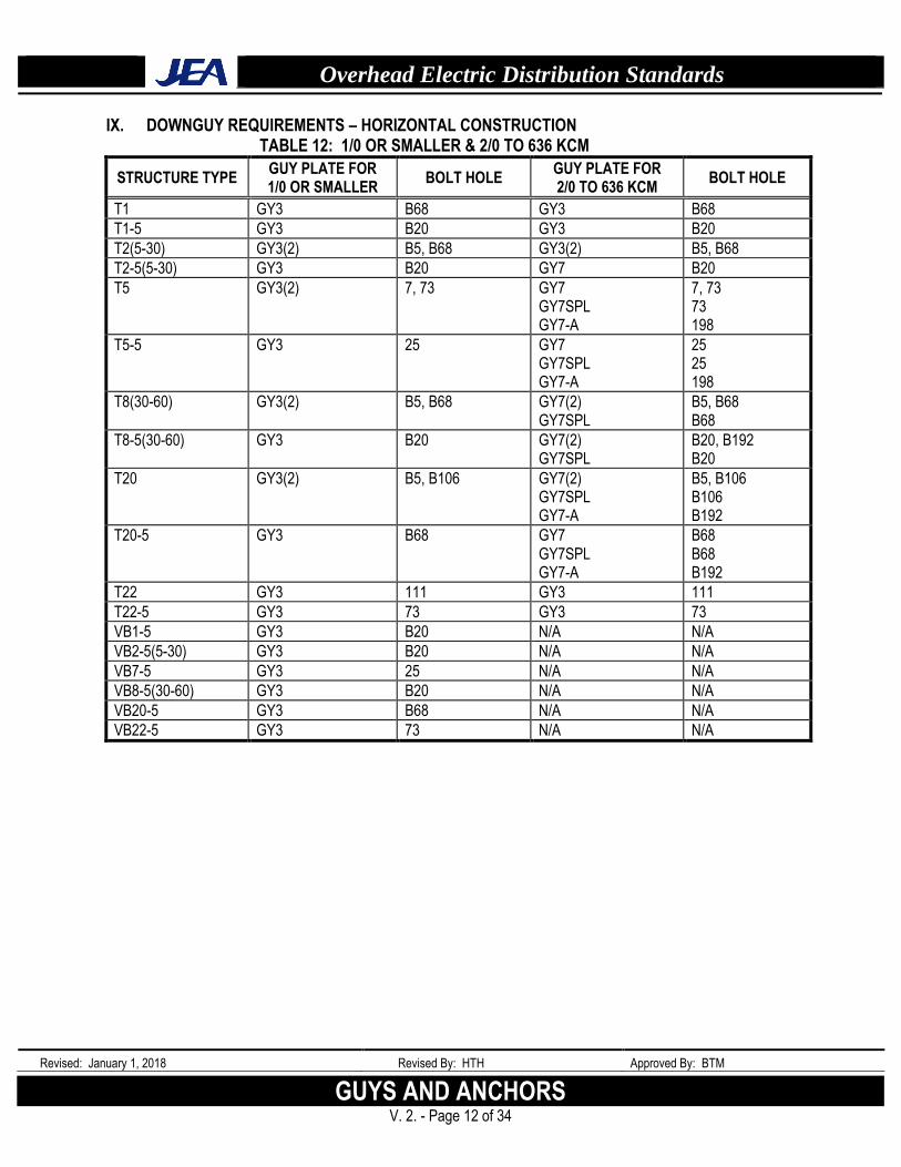
IX. DOWNGUY REQUIREMENTS – HORIZONTAL CONSTRUCTION TABLE 12: 1/0 OR SMALLER & 2/0 TO 636 KCM
STRUCTURE TYPE GUY PLATE FOR 1/0 OR SMALLER
BOLT HOLE GUY PLATE FOR 2/0 TO 636 KCM
BOLT HOLE
T1 GY3 B68 GY3 B68
T1-5 GY3 B20 GY3 B20
T2(5-30) GY3(2) B5, B68 GY3(2) B5, B68
T2-5(5-30) GY3 B20 GY7 B20
T5 GY3(2) 7, 73 GY7 GY7SPL GY7-A
7, 73 73 198
T5-5 GY3 25 GY7 GY7SPL GY7-A
25 25 198
T8(30-60) GY3(2) B5, B68 GY7(2) GY7SPL
B5, B68 B68
T8-5(30-60) GY3 B20 GY7(2) GY7SPL
B20, B192 B20
T20 GY3(2) B5, B106 GY7(2) GY7SPL GY7-A
B5, B106 B106 B192
T20-5 GY3 B68 GY7 GY7SPL GY7-A
B68 B68 B192
T22 GY3 111 GY3 111
T22-5 GY3 73 GY3 73
VB1-5 GY3 B20 N/A N/A
VB2-5(5-30) GY3 B20 N/A N/A
VB7-5 GY3 25 N/A N/A
VB8-5(30-60) GY3 B20 N/A N/A
VB20-5 GY3 B68 N/A N/A
VB22-5 GY3 73 N/A N/A
Overhead Electric Distribution Standards
Revised: January 1, 2018 Revised By: HTH Approved By: BTM
GUYS & ANCHORS V. 2. - Page 13 of 34
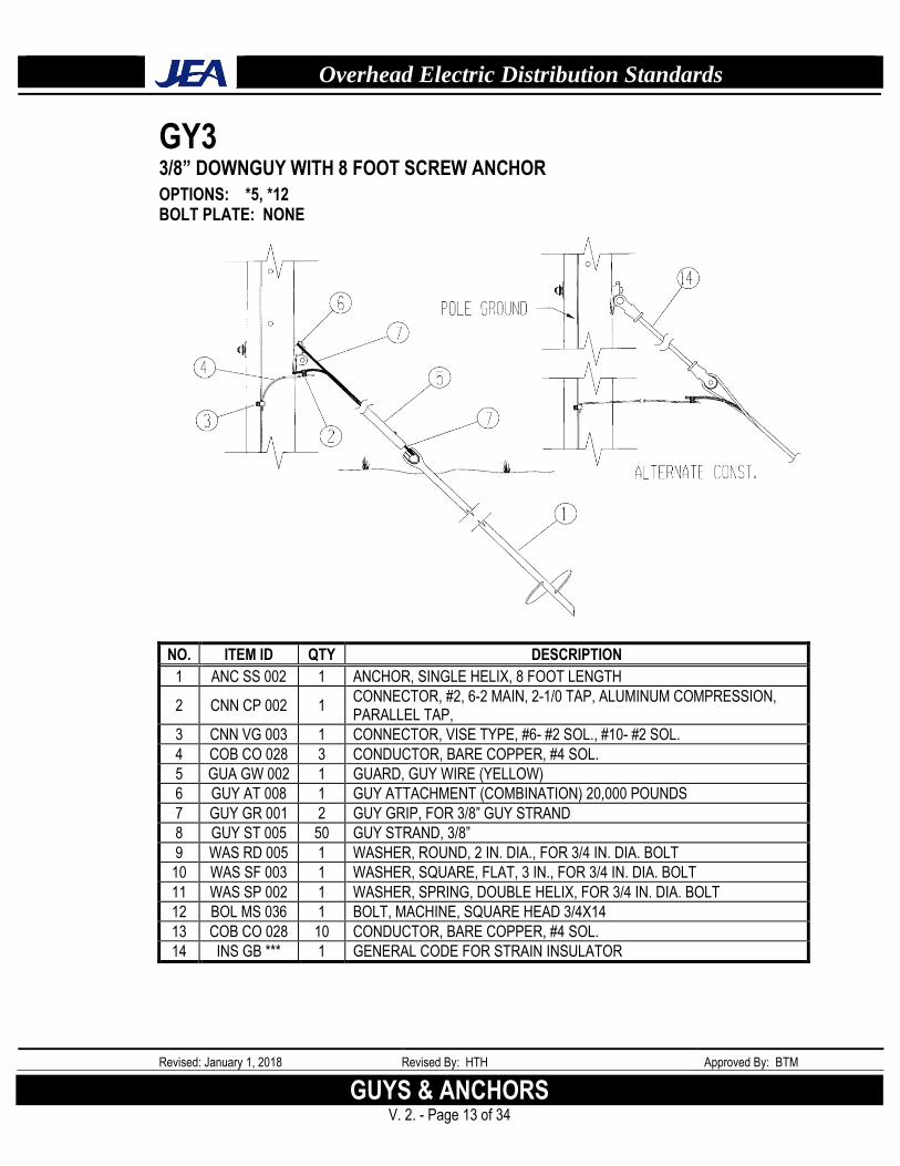
GY3 3/8” DOWNGUY WITH 8 FOOT SCREW ANCHOR
OPTIONS: *5, *12 BOLT PLATE: NONE
NO. ITEM ID QTY DESCRIPTION
1 ANC SS 002 1 ANCHOR, SINGLE HELIX, 8 FOOT LENGTH
2 CNN CP 002 1 CONNECTOR, #2, 6-2 MAIN, 2-1/0 TAP, ALUMINUM COMPRESSION, PARALLEL TAP,
3 CNN VG 003 1 CONNECTOR, VISE TYPE, #6- #2 SOL., #10- #2 SOL.
4 COB CO 028 3 CONDUCTOR, BARE COPPER, #4 SOL.
5 GUA GW 002 1 GUARD, GUY WIRE (YELLOW)
6 GUY AT 008 1 GUY ATTACHMENT (COMBINATION) 20,000 POUNDS
7 GUY GR 001 2 GUY GRIP, FOR 3/8” GUY STRAND
8 GUY ST 005 50 GUY STRAND, 3/8”
9 WAS RD 005 1 WASHER, ROUND, 2 IN. DIA., FOR 3/4 IN. DIA. BOLT
10 WAS SF 003 1 WASHER, SQUARE, FLAT, 3 IN., FOR 3/4 IN. DIA. BOLT
11 WAS SP 002 1 WASHER, SPRING, DOUBLE HELIX, FOR 3/4 IN. DIA. BOLT
12 BOL MS 036 1 BOLT, MACHINE, SQUARE HEAD 3/4X14
13 COB CO 028 10 CONDUCTOR, BARE COPPER, #4 SOL.
14 INS GB *** 1 GENERAL CODE FOR STRAIN INSULATOR
Overhead Electric Distribution Standards
Revised: January 1, 2018 Revised By: HTH Approved By: BTM
GUYS AND ANCHORS V. 2. - Page 14 of 34
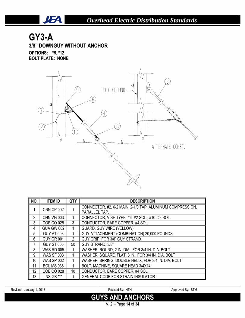
GY3-A 3/8” DOWNGUY WITHOUT ANCHOR
OPTIONS: *5, *12 BOLT PLATE: NONE
NO. ITEM ID QTY DESCRIPTION
1 CNN CP 002 1 CONNECTOR, #2, 6-2 MAIN, 2-1/0 TAP, ALUMINUM COMPRESSION, PARALLEL TAP,
2 CNN VG 003 1 CONNECTOR, VISE TYPE, #6- #2 SOL., #10- #2 SOL.
3 COB CO 028 3 CONDUCTOR, BARE COPPER, #4 SOL.
4 GUA GW 002 1 GUARD, GUY WIRE (YELLOW)
5 GUY AT 008 1 GUY ATTACHMENT (COMBINATION) 20,000 POUNDS
6 GUY GR 001 2 GUY GRIP, FOR 3/8” GUY STRAND
7 GUY ST 005 50 GUY STRAND, 3/8”
8 WAS RD 005 1 WASHER, ROUND, 2 IN. DIA., FOR 3/4 IN. DIA. BOLT
9 WAS SF 003 1 WASHER, SQUARE, FLAT, 3 IN., FOR 3/4 IN. DIA. BOLT
10 WAS SP 002 1 WASHER, SPRING, DOUBLE HELIX, FOR 3/4 IN. DIA. BOLT
11 BOL MS 036 1 BOLT, MACHINE, SQUARE HEAD 3/4X14
12 COB CO 028 10 CONDUCTOR, BARE COPPER, #4 SOL.
13 INS GB *** 1 GENERAL CODE FOR STRAIN INSULATOR
Overhead Electric Distribution Standards
Revised: January 1, 2018 Revised By: HTH Approved By: BTM
GUYS & ANCHORS V. 2. - Page 15 of 34
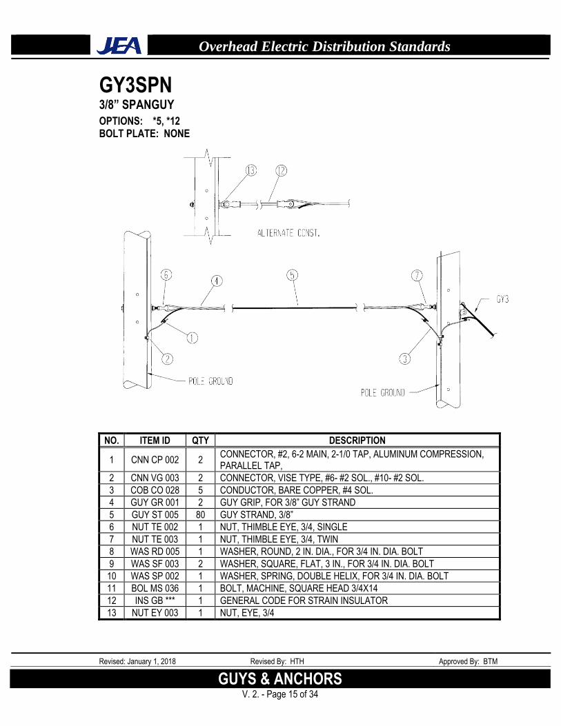
GY3SPN 3/8” SPANGUY
OPTIONS: *5, *12 BOLT PLATE: NONE
NO. ITEM ID QTY DESCRIPTION
1 CNN CP 002 2 CONNECTOR, #2, 6-2 MAIN, 2-1/0 TAP, ALUMINUM COMPRESSION, PARALLEL TAP,
2 CNN VG 003 2 CONNECTOR, VISE TYPE, #6- #2 SOL., #10- #2 SOL.
3 COB CO 028 5 CONDUCTOR, BARE COPPER, #4 SOL.
4 GUY GR 001 2 GUY GRIP, FOR 3/8” GUY STRAND
5 GUY ST 005 80 GUY STRAND, 3/8”
6 NUT TE 002 1 NUT, THIMBLE EYE, 3/4, SINGLE
7 NUT TE 003 1 NUT, THIMBLE EYE, 3/4, TWIN
8 WAS RD 005 1 WASHER, ROUND, 2 IN. DIA., FOR 3/4 IN. DIA. BOLT
9 WAS SF 003 2 WASHER, SQUARE, FLAT, 3 IN., FOR 3/4 IN. DIA. BOLT
10 WAS SP 002 1 WASHER, SPRING, DOUBLE HELIX, FOR 3/4 IN. DIA. BOLT
11 BOL MS 036 1 BOLT, MACHINE, SQUARE HEAD 3/4X14
12 INS GB *** 1 GENERAL CODE FOR STRAIN INSULATOR
13 NUT EY 003 1 NUT, EYE, 3/4
Overhead Electric Distribution Standards
Revised: January 1, 2018 Revised By: HTH Approved By: BTM
GUYS AND ANCHORS V. 2. - Page 16 of 34
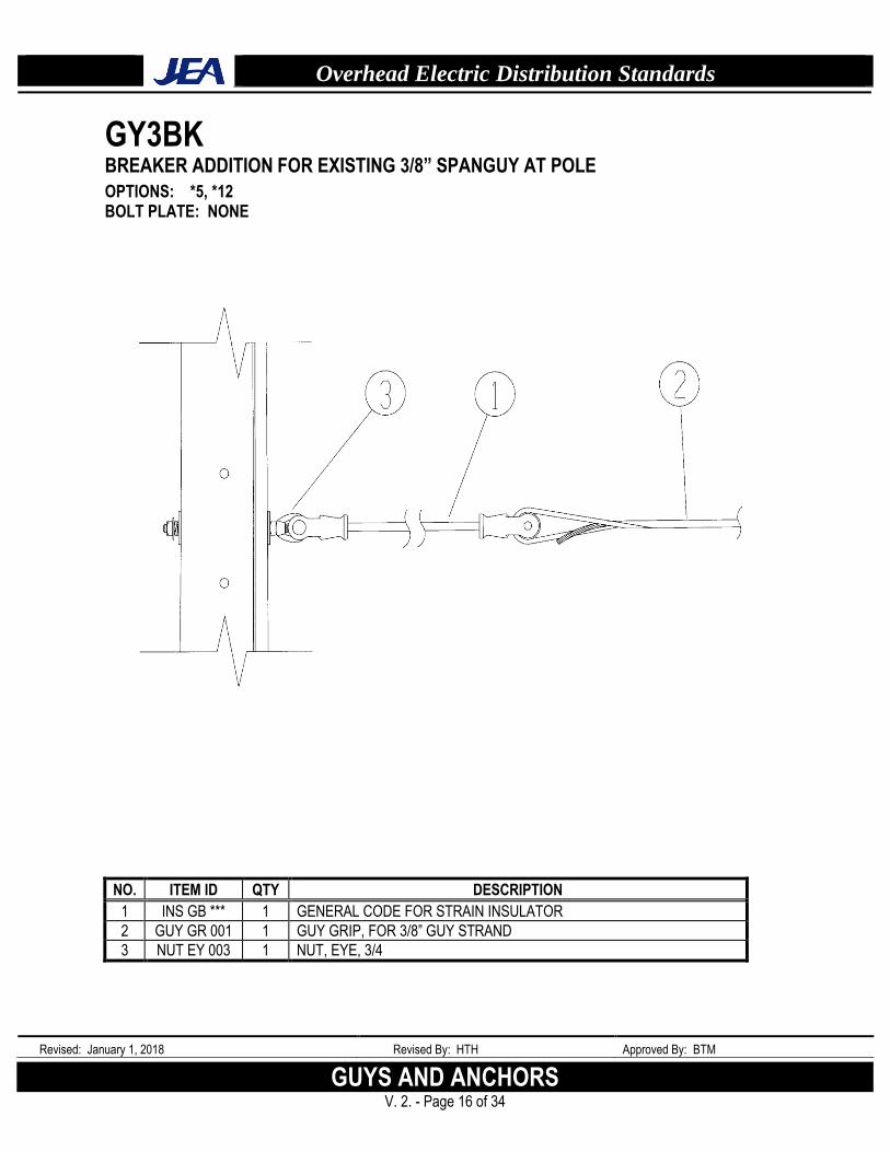
GY3BK BREAKER ADDITION FOR EXISTING 3/8” SPANGUY AT POLE
OPTIONS: *5, *12 BOLT PLATE: NONE
NO. ITEM ID QTY DESCRIPTION
1 INS GB *** 1 GENERAL CODE FOR STRAIN INSULATOR
2 GUY GR 001 1 GUY GRIP, FOR 3/8” GUY STRAND
3 NUT EY 003 1 NUT, EYE, 3/4
Overhead Electric Distribution Standards
Revised: January 1, 2018 Revised By: HTH Approved By: BTM
GUYS & ANCHORS V. 2. - Page 17 of 34
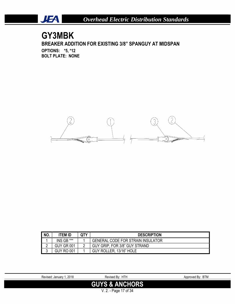
GY3MBK BREAKER ADDITION FOR EXISTING 3/8” SPANGUY AT MIDSPAN
OPTIONS: *5, *12 BOLT PLATE: NONE
NO. ITEM ID QTY DESCRIPTION
1 INS GB *** 1 GENERAL CODE FOR STRAIN INSULATOR
2 GUY GR 001 2 GUY GRIP, FOR 3/8” GUY STRAND
3 GUY RO 001 1 GUY ROLLER, 13/16” HOLE
Overhead Electric Distribution Standards
Revised: January 1, 2018 Revised By: HTH Approved By: BTM
GUYS AND ANCHORS V. 2. - Page 18 of 34
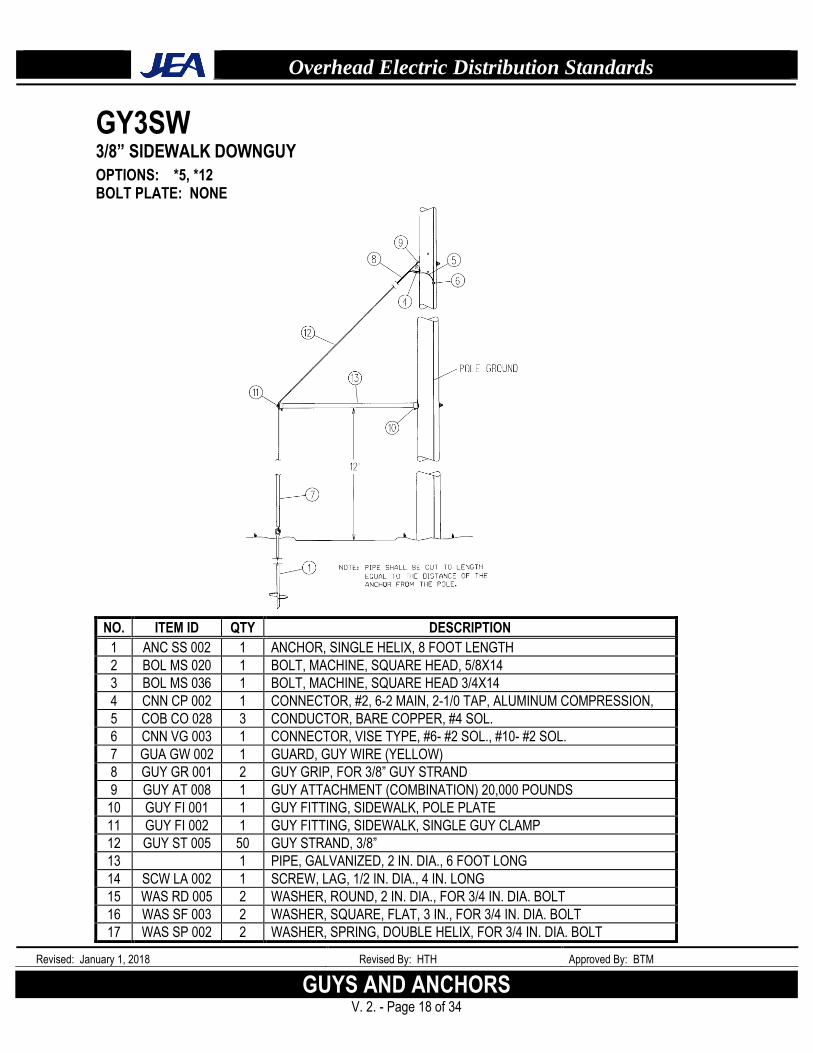
GY3SW 3/8” SIDEWALK DOWNGUY
OPTIONS: *5, *12 BOLT PLATE: NONE
NO. ITEM ID QTY DESCRIPTION
1 ANC SS 002 1 ANCHOR, SINGLE HELIX, 8 FOOT LENGTH
2 BOL MS 020 1 BOLT, MACHINE, SQUARE HEAD, 5/8X14
3 BOL MS 036 1 BOLT, MACHINE, SQUARE HEAD 3/4X14
4 CNN CP 002 1 CONNECTOR, #2, 6-2 MAIN, 2-1/0 TAP, ALUMINUM COMPRESSION,
5 COB CO 028 3 CONDUCTOR, BARE COPPER, #4 SOL.
6 CNN VG 003 1 CONNECTOR, VISE TYPE, #6- #2 SOL., #10- #2 SOL.
7 GUA GW 002 1 GUARD, GUY WIRE (YELLOW)
8 GUY GR 001 2 GUY GRIP, FOR 3/8” GUY STRAND
9 GUY AT 008 1 GUY ATTACHMENT (COMBINATION) 20,000 POUNDS
10 GUY FI 001 1 GUY FITTING, SIDEWALK, POLE PLATE
11 GUY FI 002 1 GUY FITTING, SIDEWALK, SINGLE GUY CLAMP
12 GUY ST 005 50 GUY STRAND, 3/8”
13 1 PIPE, GALVANIZED, 2 IN. DIA., 6 FOOT LONG
14 SCW LA 002 1 SCREW, LAG, 1/2 IN. DIA., 4 IN. LONG
15 WAS RD 005 2 WASHER, ROUND, 2 IN. DIA., FOR 3/4 IN. DIA. BOLT
16 WAS SF 003 2 WASHER, SQUARE, FLAT, 3 IN., FOR 3/4 IN. DIA. BOLT
17 WAS SP 002 2 WASHER, SPRING, DOUBLE HELIX, FOR 3/4 IN. DIA. BOLT
Overhead Electric Distribution Standards
Revised: January 1, 2018 Revised By: HTH Approved By: BTM
GUYS & ANCHORS V. 2. - Page 19 of 34
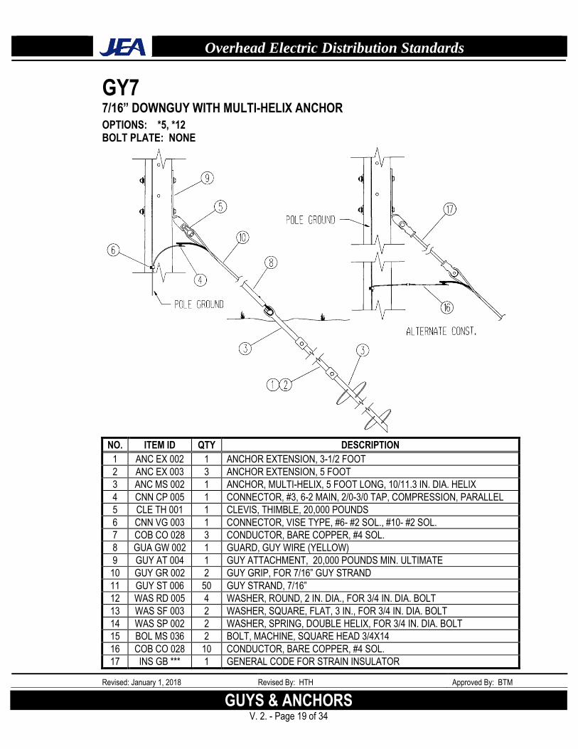
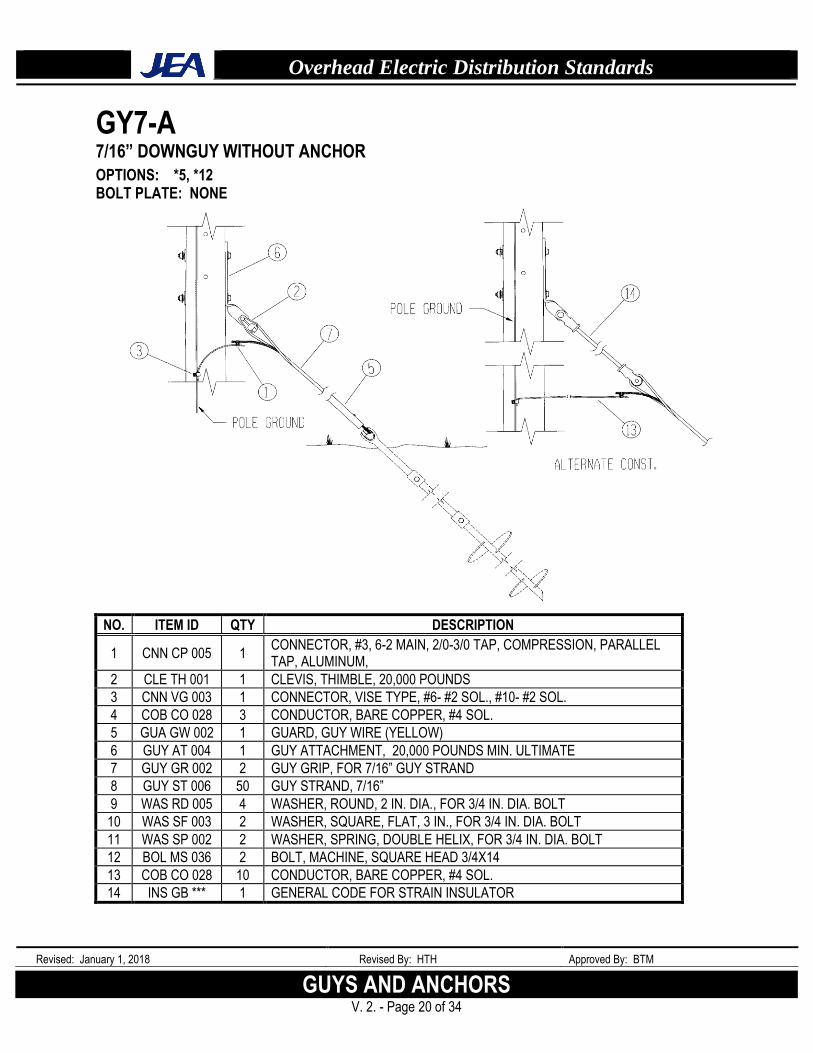
GY7 7/16” DOWNGUY WITH MULTI-HELIX ANCHOR
OPTIONS: *5, *12 BOLT PLATE: NONE
NO. ITEM ID QTY DESCRIPTION
1 ANC EX 002 1 ANCHOR EXTENSION, 3-1/2 FOOT
2 ANC EX 003 3 ANCHOR EXTENSION, 5 FOOT
3 ANC MS 002 1 ANCHOR, MULTI-HELIX, 5 FOOT LONG, 10/11.3 IN. DIA. HELIX
4 CNN CP 005 1 CONNECTOR, #3, 6-2 MAIN, 2/0-3/0 TAP, COMPRESSION, PARALLEL
5 CLE TH 001 1 CLEVIS, THIMBLE, 20,000 POUNDS
6 CNN VG 003 1 CONNECTOR, VISE TYPE, #6- #2 SOL., #10- #2 SOL.
7 COB CO 028 3 CONDUCTOR, BARE COPPER, #4 SOL.
8 GUA GW 002 1 GUARD, GUY WIRE (YELLOW)
9 GUY AT 004 1 GUY ATTACHMENT, 20,000 POUNDS MIN. ULTIMATE
10 GUY GR 002 2 GUY GRIP, FOR 7/16” GUY STRAND
11 GUY ST 006 50 GUY STRAND, 7/16”
12 WAS RD 005 4 WASHER, ROUND, 2 IN. DIA., FOR 3/4 IN. DIA. BOLT
13 WAS SF 003 2 WASHER, SQUARE, FLAT, 3 IN., FOR 3/4 IN. DIA. BOLT
14 WAS SP 002 2 WASHER, SPRING, DOUBLE HELIX, FOR 3/4 IN. DIA. BOLT
15 BOL MS 036 2 BOLT, MACHINE, SQUARE HEAD 3/4X14
16 COB CO 028 10 CONDUCTOR, BARE COPPER, #4 SOL.
17 INS GB *** 1 GENERAL CODE FOR STRAIN INSULATOR
Overhead Electric Distribution Standards
Revised: January 1, 2018 Revised By: HTH Approved By: BTM
GUYS AND ANCHORS V. 2. - Page 20 of 34
GY7-A 7/16” DOWNGUY WITHOUT ANCHOR
OPTIONS: *5, *12 BOLT PLATE: NONE
NO. ITEM ID QTY DESCRIPTION
1 CNN CP 005 1 CONNECTOR, #3, 6-2 MAIN, 2/0-3/0 TAP, COMPRESSION, PARALLEL TAP, ALUMINUM,
2 CLE TH 001 1 CLEVIS, THIMBLE, 20,000 POUNDS
3 CNN VG 003 1 CONNECTOR, VISE TYPE, #6- #2 SOL., #10- #2 SOL.
4 COB CO 028 3 CONDUCTOR, BARE COPPER, #4 SOL.
5 GUA GW 002 1 GUARD, GUY WIRE (YELLOW)
6 GUY AT 004 1 GUY ATTACHMENT, 20,000 POUNDS MIN. ULTIMATE
7 GUY GR 002 2 GUY GRIP, FOR 7/16” GUY STRAND
8 GUY ST 006 50 GUY STRAND, 7/16”
9 WAS RD 005 4 WASHER, ROUND, 2 IN. DIA., FOR 3/4 IN. DIA. BOLT
10 WAS SF 003 2 WASHER, SQUARE, FLAT, 3 IN., FOR 3/4 IN. DIA. BOLT
11 WAS SP 002 2 WASHER, SPRING, DOUBLE HELIX, FOR 3/4 IN. DIA. BOLT
12 BOL MS 036 2 BOLT, MACHINE, SQUARE HEAD 3/4X14
13 COB CO 028 10 CONDUCTOR, BARE COPPER, #4 SOL.
14 INS GB *** 1 GENERAL CODE FOR STRAIN INSULATOR
Overhead Electric Distribution Standards
Revised: January 1, 2018 Revised By: HTH Approved By: BTM
GUYS & ANCHORS V. 2. - Page 21 of 34
GY7SPN 7/16” SPANGUY
OPTIONS: *5, *12 BOLT PLATE: NONE
NO. ITEM ID QTY DESCRIPTION
1 CNN CP 005 2 CONNECTOR, #3, 6-2 MAIN, 2/0-3/0 TAP, COMPRESSION, PARALLEL TAP, ALUMINUM,
2 CNN VG 003 2 CONNECTOR, VISE TYPE, #6- #2 SOL., #10- #2 SOL.
3 COB CO 028 5 CONDUCTOR, BARE COPPER, #4 SOL.
4 GUY GR 002 2 GUY GRIP, FOR 7/16” GUY STRAND
5 GUY ST 006 80 GUY STRAND, 7/16”
6 NUT TE 002 1 NUT, THIMBLE EYE, 3/4, SINGLE
7 NUT TE 003 1 NUT, THIMBLE EYE, 3/4, TWIN
8 WAS RD 005 1 WASHER, ROUND, 2 IN. DIA., FOR 3/4 IN. DIA. BOLT
9 WAS SF 003 2 WASHER, SQUARE, FLAT, 3 IN., FOR 3/4 IN. DIA. BOLT
10 WAS SP 002 1 WASHER, SPRING, DOUBLE HELIX, FOR 3/4 IN. DIA. BOLT
11 BOL MS 036 1 BOLT, MACHINE, SQUARE HEAD 3/4X14
12 INS GB *** 1 GENERAL CODE FOR STRAIN INSULATOR
13 NUT EY 003 1 NUT, EYE, 3/4
Overhead Electric Distribution Standards
Revised: January 1, 2018 Revised By: HTH Approved By: BTM
GUYS AND ANCHORS V. 2. - Page 22 of 34
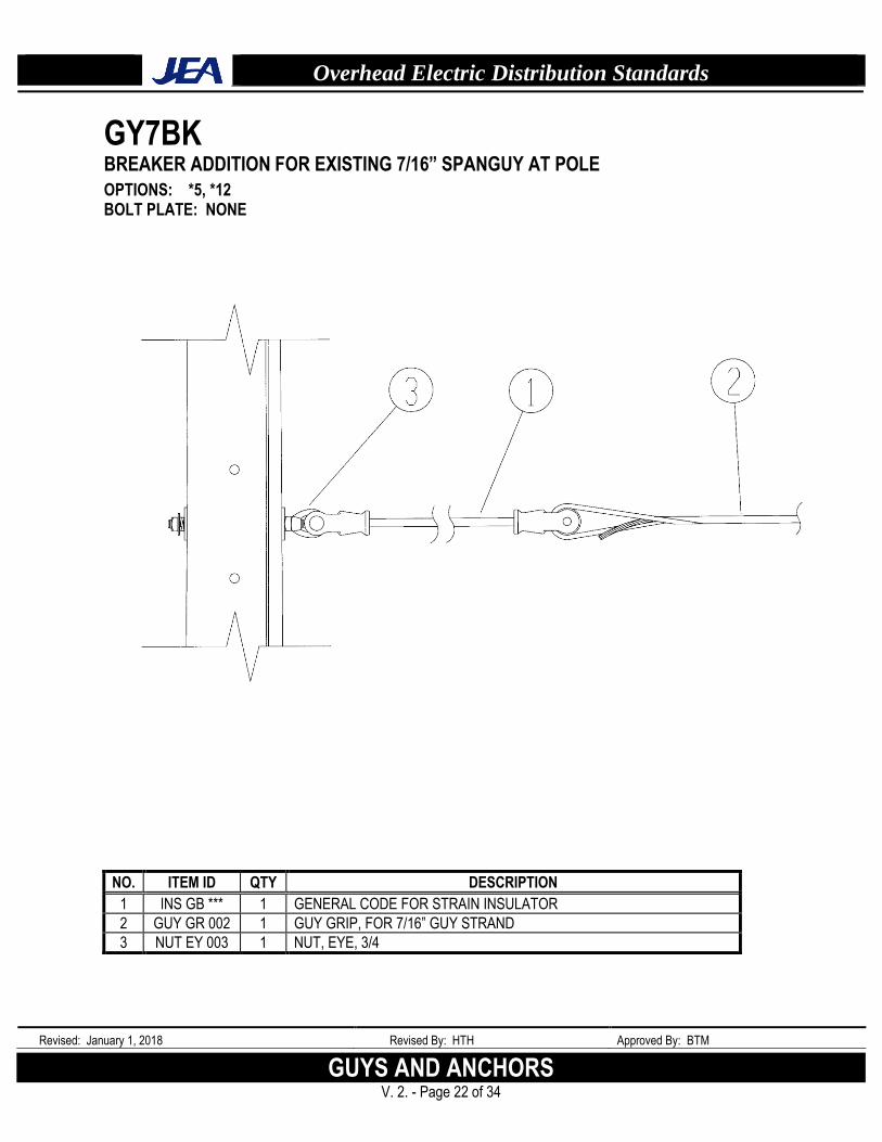
GY7BK BREAKER ADDITION FOR EXISTING 7/16” SPANGUY AT POLE
OPTIONS: *5, *12 BOLT PLATE: NONE
NO. ITEM ID QTY DESCRIPTION
1 INS GB *** 1 GENERAL CODE FOR STRAIN INSULATOR
2 GUY GR 002 1 GUY GRIP, FOR 7/16” GUY STRAND
3 NUT EY 003 1 NUT, EYE, 3/4

Overhead Electric Distribution Standards
Revised: January 1, 2018 Revised By: HTH Approved By: BTM
GUYS & ANCHORS V. 2. - Page 23 of 34
GY7MBK BREAKER ADDITION FOR EXISTING 7/16” SPANGUY AT MIDSPAN
OPTIONS: *5, *12 BOLT PLATE: NONE
NO. ITEM ID QTY DESCRIPTION
1 INS GB *** 1 GENERAL CODE FOR STRAIN INSULATOR
2 GUY GR 002 2 GUY GRIP, FOR 7/16” GUY STRAND
3 GUY RO 001 1 GUY ROLLER, 13/16” HOLE
Overhead Electric Distribution Standards
Revised: January 1, 2018 Revised By: HTH Approved By: BTM
GUYS AND ANCHORS V. 2. - Page 24 of 34
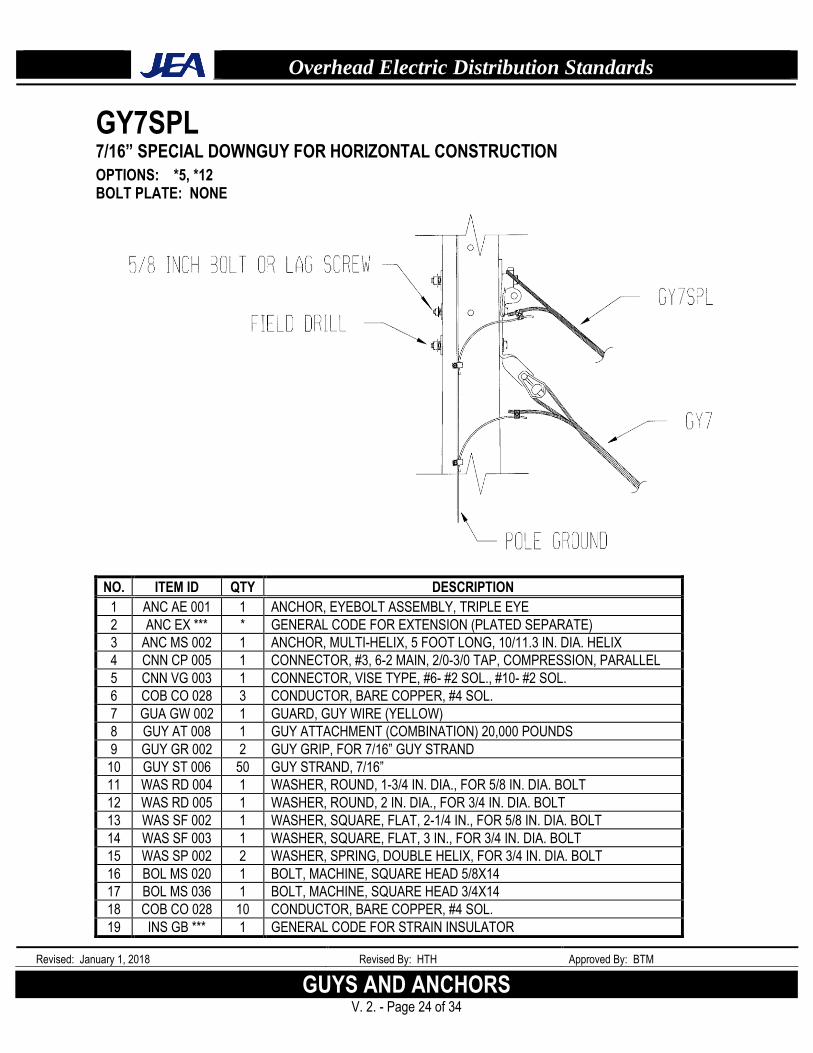
GY7SPL 7/16” SPECIAL DOWNGUY FOR HORIZONTAL CONSTRUCTION
OPTIONS: *5, *12 BOLT PLATE: NONE
NO. ITEM ID QTY DESCRIPTION
1 ANC AE 001 1 ANCHOR, EYEBOLT ASSEMBLY, TRIPLE EYE
2 ANC EX *** * GENERAL CODE FOR EXTENSION (PLATED SEPARATE)
3 ANC MS 002 1 ANCHOR, MULTI-HELIX, 5 FOOT LONG, 10/11.3 IN. DIA. HELIX
4 CNN CP 005 1 CONNECTOR, #3, 6-2 MAIN, 2/0-3/0 TAP, COMPRESSION, PARALLEL
5 CNN VG 003 1 CONNECTOR, VISE TYPE, #6- #2 SOL., #10- #2 SOL.
6 COB CO 028 3 CONDUCTOR, BARE COPPER, #4 SOL.
7 GUA GW 002 1 GUARD, GUY WIRE (YELLOW)
8 GUY AT 008 1 GUY ATTACHMENT (COMBINATION) 20,000 POUNDS
9 GUY GR 002 2 GUY GRIP, FOR 7/16” GUY STRAND
10 GUY ST 006 50 GUY STRAND, 7/16”
11 WAS RD 004 1 WASHER, ROUND, 1-3/4 IN. DIA., FOR 5/8 IN. DIA. BOLT
12 WAS RD 005 1 WASHER, ROUND, 2 IN. DIA., FOR 3/4 IN. DIA. BOLT
13 WAS SF 002 1 WASHER, SQUARE, FLAT, 2-1/4 IN., FOR 5/8 IN. DIA. BOLT
14 WAS SF 003 1 WASHER, SQUARE, FLAT, 3 IN., FOR 3/4 IN. DIA. BOLT
15 WAS SP 002 2 WASHER, SPRING, DOUBLE HELIX, FOR 3/4 IN. DIA. BOLT
16 BOL MS 020 1 BOLT, MACHINE, SQUARE HEAD 5/8X14
17 BOL MS 036 1 BOLT, MACHINE, SQUARE HEAD 3/4X14
18 COB CO 028 10 CONDUCTOR, BARE COPPER, #4 SOL.
19 INS GB *** 1 GENERAL CODE FOR STRAIN INSULATOR
Overhead Electric Distribution Standards
Revised: January 1, 2018 Revised By: HTH Approved By: BTM
GUYS & ANCHORS V. 2. - Page 25 of 34
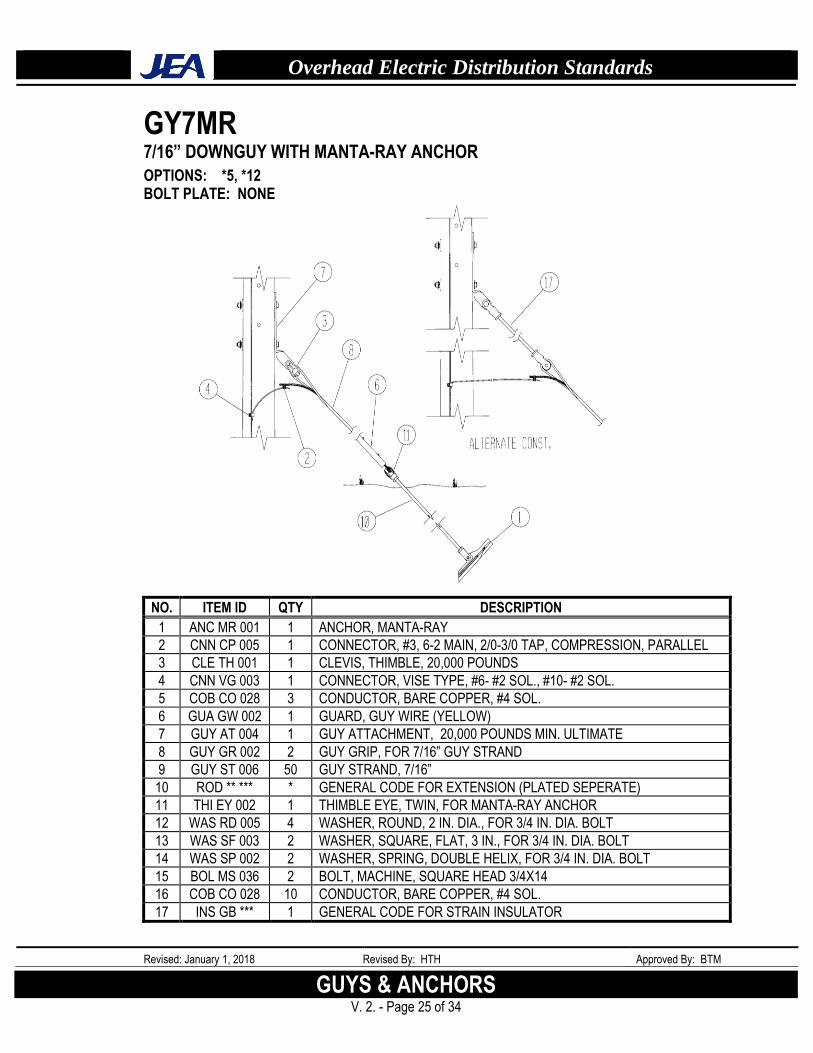
GY7MR 7/16” DOWNGUY WITH MANTA-RAY ANCHOR
OPTIONS: *5, *12 BOLT PLATE: NONE
NO. ITEM ID QTY DESCRIPTION
1 ANC MR 001 1 ANCHOR, MANTA-RAY
2 CNN CP 005 1 CONNECTOR, #3, 6-2 MAIN, 2/0-3/0 TAP, COMPRESSION, PARALLEL
3 CLE TH 001 1 CLEVIS, THIMBLE, 20,000 POUNDS
4 CNN VG 003 1 CONNECTOR, VISE TYPE, #6- #2 SOL., #10- #2 SOL.
5 COB CO 028 3 CONDUCTOR, BARE COPPER, #4 SOL.
6 GUA GW 002 1 GUARD, GUY WIRE (YELLOW)
7 GUY AT 004 1 GUY ATTACHMENT, 20,000 POUNDS MIN. ULTIMATE
8 GUY GR 002 2 GUY GRIP, FOR 7/16” GUY STRAND
9 GUY ST 006 50 GUY STRAND, 7/16”
10 ROD ** *** * GENERAL CODE FOR EXTENSION (PLATED SEPERATE)
11 THI EY 002 1 THIMBLE EYE, TWIN, FOR MANTA-RAY ANCHOR
12 WAS RD 005 4 WASHER, ROUND, 2 IN. DIA., FOR 3/4 IN. DIA. BOLT
13 WAS SF 003 2 WASHER, SQUARE, FLAT, 3 IN., FOR 3/4 IN. DIA. BOLT
14 WAS SP 002 2 WASHER, SPRING, DOUBLE HELIX, FOR 3/4 IN. DIA. BOLT
15 BOL MS 036 2 BOLT, MACHINE, SQUARE HEAD 3/4X14
16 COB CO 028 10 CONDUCTOR, BARE COPPER, #4 SOL.
17 INS GB *** 1 GENERAL CODE FOR STRAIN INSULATOR
Overhead Electric Distribution Standards
Revised: January 1, 2018 Revised By: HTH Approved By: BTM
GUYS AND ANCHORS V. 2. - Page 26 of 34
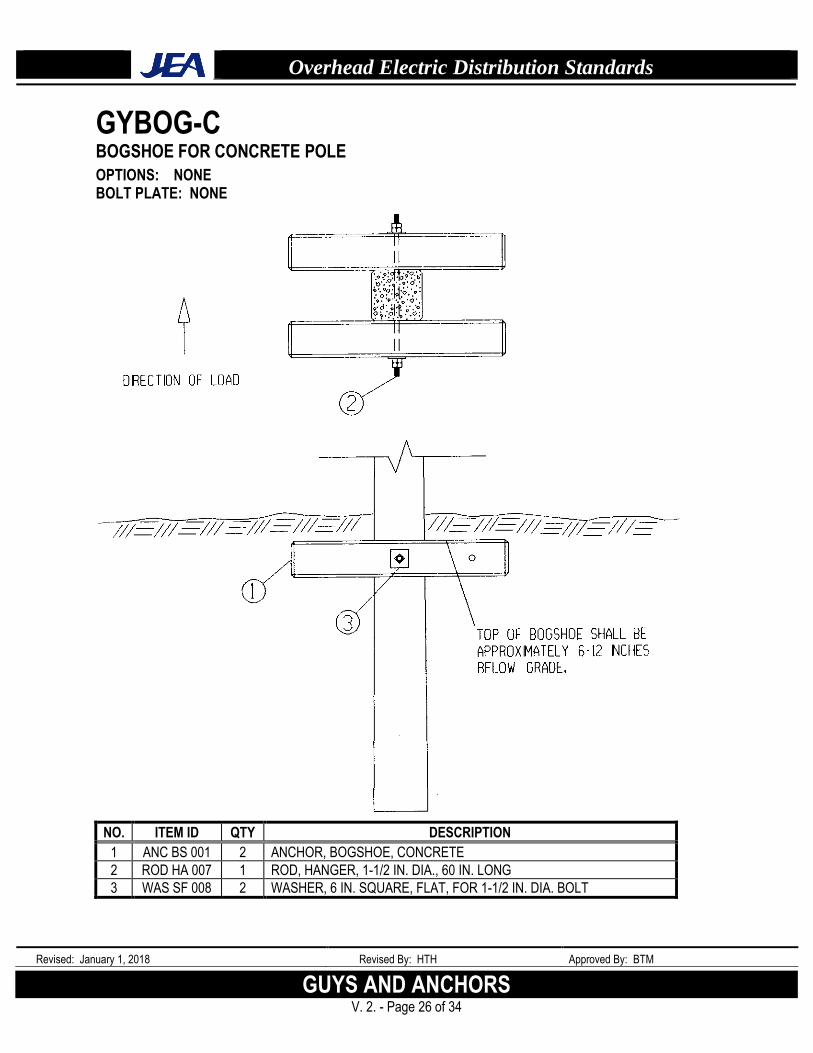
GYBOG-C BOGSHOE FOR CONCRETE POLE
OPTIONS: NONE BOLT PLATE: NONE
NO. ITEM ID QTY DESCRIPTION
1 ANC BS 001 2 ANCHOR, BOGSHOE, CONCRETE
2 ROD HA 007 1 ROD, HANGER, 1-1/2 IN. DIA., 60 IN. LONG
3 WAS SF 008 2 WASHER, 6 IN. SQUARE, FLAT, FOR 1-1/2 IN. DIA. BOLT
Overhead Electric Distribution Standards
Revised: January 1, 2018 Revised By: HTH Approved By: BTM
GUYS & ANCHORS V. 2. - Page 27 of 34
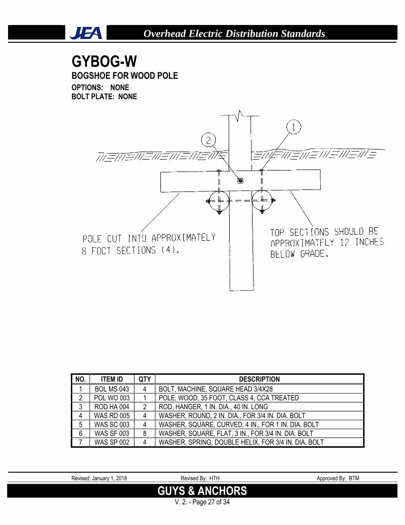
GYBOG-W BOGSHOE FOR WOOD POLE
OPTIONS: NONE BOLT PLATE: NONE
NO. ITEM ID QTY DESCRIPTION
1 BOL MS 043 4 BOLT, MACHINE, SQUARE HEAD 3/4X28
2 POL WO 003 1 POLE, WOOD, 35 FOOT, CLASS 4, CCA TREATED
3 ROD HA 004 2 ROD, HANGER, 1 IN. DIA., 40 IN. LONG
4 WAS RD 005 4 WASHER, ROUND, 2 IN. DIA., FOR 3/4 IN. DIA. BOLT
5 WAS SC 003 4 WASHER, SQUARE, CURVED, 4 IN., FOR 1 IN. DIA. BOLT
6 WAS SF 003 8 WASHER, SQUARE, FLAT, 3 IN., FOR 3/4 IN. DIA. BOLT
7 WAS SP 002 4 WASHER, SPRING, DOUBLE HELIX, FOR 3/4 IN. DIA. BOLT
Overhead Electric Distribution Standards
Revised: January 1, 2018 Revised By: HTH Approved By: BTM
GUYS AND ANCHORS V. 2. - Page 28 of 34
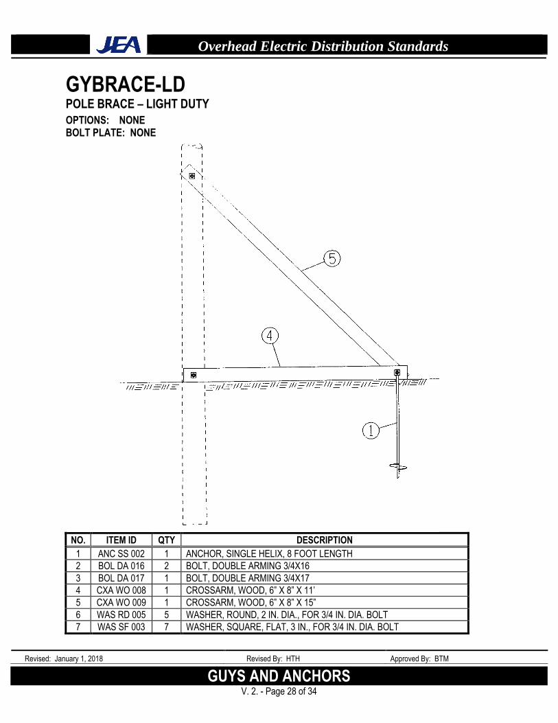
GYBRACE-LD POLE BRACE – LIGHT DUTY
OPTIONS: NONE BOLT PLATE: NONE
NO. ITEM ID QTY DESCRIPTION
1 ANC SS 002 1 ANCHOR, SINGLE HELIX, 8 FOOT LENGTH
2 BOL DA 016 2 BOLT, DOUBLE ARMING 3/4X16
3 BOL DA 017 1 BOLT, DOUBLE ARMING 3/4X17
4 CXA WO 008 1 CROSSARM, WOOD, 6” X 8” X 11’
5 CXA WO 009 1 CROSSARM, WOOD, 6” X 8” X 15”
6 WAS RD 005 5 WASHER, ROUND, 2 IN. DIA., FOR 3/4 IN. DIA. BOLT
7 WAS SF 003 7 WASHER, SQUARE, FLAT, 3 IN., FOR 3/4 IN. DIA. BOLT
Overhead Electric Distribution Standards
Revised: January 1, 2018 Revised By: HTH Approved By: BTM
GUYS & ANCHORS V. 2. - Page 29 of 34
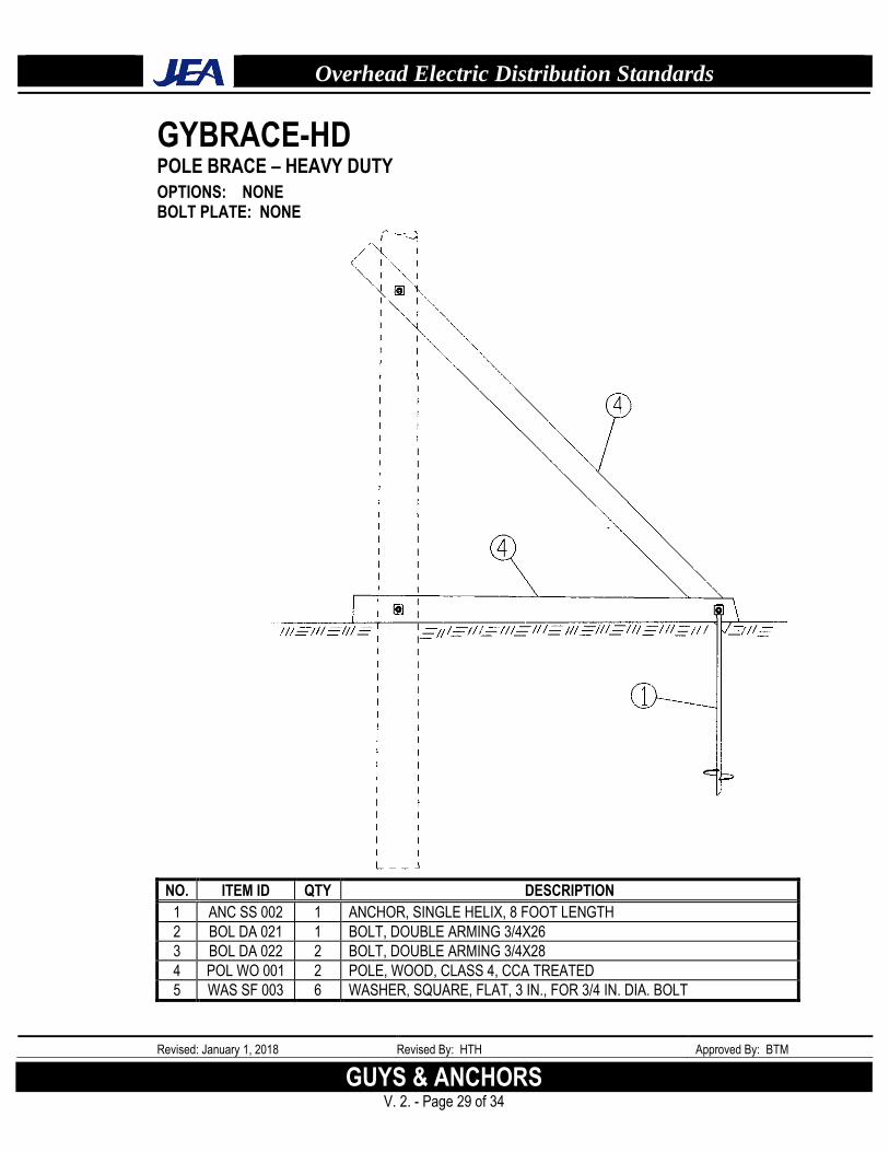
GYBRACE-HD POLE BRACE – HEAVY DUTY
OPTIONS: NONE BOLT PLATE: NONE
NO. ITEM ID QTY DESCRIPTION
1 ANC SS 002 1 ANCHOR, SINGLE HELIX, 8 FOOT LENGTH
2 BOL DA 021 1 BOLT, DOUBLE ARMING 3/4X26
3 BOL DA 022 2 BOLT, DOUBLE ARMING 3/4X28
4 POL WO 001 2 POLE, WOOD, CLASS 4, CCA TREATED
5 WAS SF 003 6 WASHER, SQUARE, FLAT, 3 IN., FOR 3/4 IN. DIA. BOLT
Overhead Electric Distribution Standards
Revised: January 1, 2018 Revised By: HTH Approved By: BTM
GUYS AND ANCHORS V. 2. - Page 30 of 34
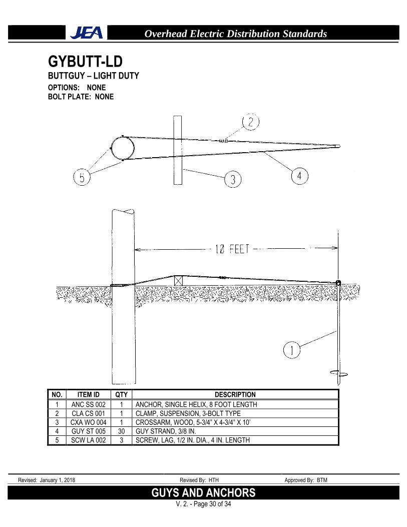
GYBUTT-LD BUTTGUY – LIGHT DUTY
OPTIONS: NONE BOLT PLATE: NONE
NO. ITEM ID QTY DESCRIPTION
1 ANC SS 002 1 ANCHOR, SINGLE HELIX, 8 FOOT LENGTH
2 CLA CS 001 1 CLAMP, SUSPENSION, 3-BOLT TYPE
3 CXA WO 004 1 CROSSARM, WOOD, 5-3/4” X 4-3/4” X 10’
4 GUY ST 005 30 GUY STRAND, 3/8 IN.
5 SCW LA 002 3 SCREW, LAG, 1/2 IN. DIA., 4 IN. LENGTH
Overhead Electric Distribution Standards
Revised: January 1, 2018 Revised By: HTH Approved By: BTM
GUYS & ANCHORS V. 2. - Page 31 of 34
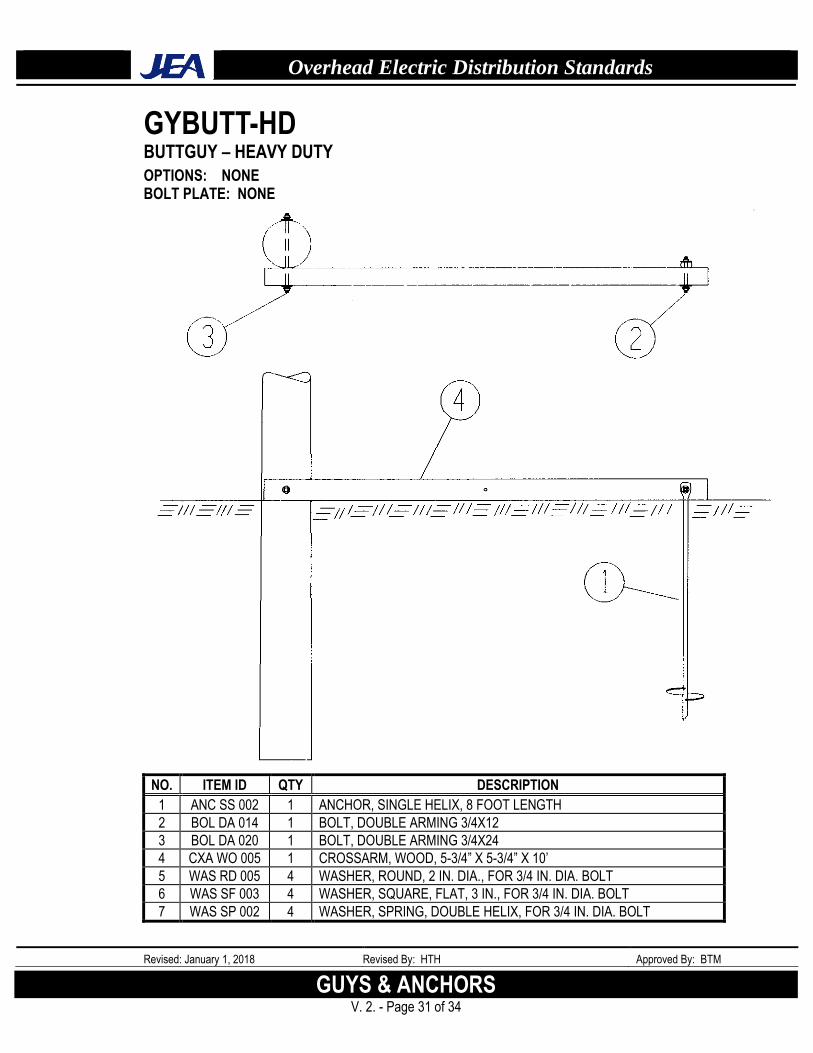
GYBUTT-HD BUTTGUY – HEAVY DUTY
OPTIONS: NONE BOLT PLATE: NONE
NO. ITEM ID QTY DESCRIPTION
1 ANC SS 002 1 ANCHOR, SINGLE HELIX, 8 FOOT LENGTH
2 BOL DA 014 1 BOLT, DOUBLE ARMING 3/4X12
3 BOL DA 020 1 BOLT, DOUBLE ARMING 3/4X24
4 CXA WO 005 1 CROSSARM, WOOD, 5-3/4” X 5-3/4” X 10’
5 WAS RD 005 4 WASHER, ROUND, 2 IN. DIA., FOR 3/4 IN. DIA. BOLT
6 WAS SF 003 4 WASHER, SQUARE, FLAT, 3 IN., FOR 3/4 IN. DIA. BOLT
7 WAS SP 002 4 WASHER, SPRING, DOUBLE HELIX, FOR 3/4 IN. DIA. BOLT
Overhead Electric Distribution Standards
Revised: January 1, 2018 Revised By: HTH Approved By: BTM
GUYS AND ANCHORS V. 2. - Page 32 of 34
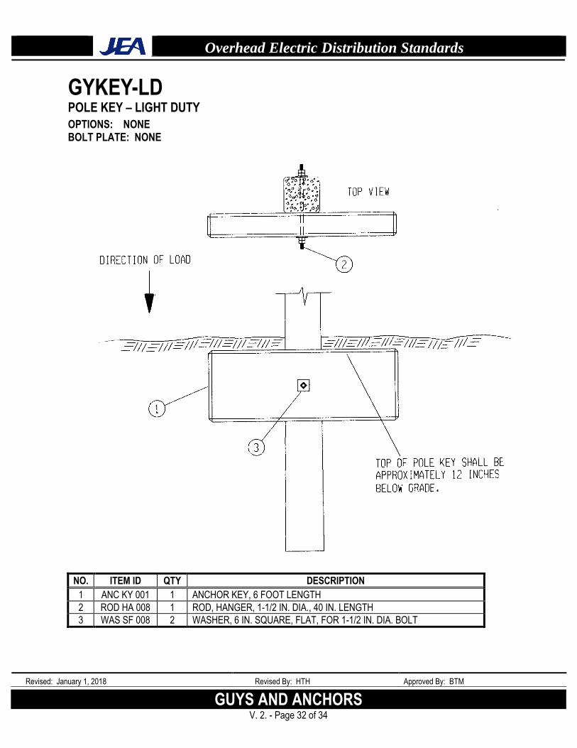
GYKEY-LD POLE KEY – LIGHT DUTY
OPTIONS: NONE BOLT PLATE: NONE
NO. ITEM ID QTY DESCRIPTION
1 ANC KY 001 1 ANCHOR KEY, 6 FOOT LENGTH
2 ROD HA 008 1 ROD, HANGER, 1-1/2 IN. DIA., 40 IN. LENGTH
3 WAS SF 008 2 WASHER, 6 IN. SQUARE, FLAT, FOR 1-1/2 IN. DIA. BOLT
Overhead Electric Distribution Standards
Revised: January 1, 2018 Revised By: HTH Approved By: BTM
GUYS & ANCHORS V. 2. - Page 33 of 34
GYKEY-HD POLE KEY – HEAVY DUTY
OPTIONS: NONE BOLT PLATE: NONE
NO. ITEM ID QTY DESCRIPTION
1 ANC KY 002 1 ANCHOR KEY, 8 FOOT LENGTH
2 ROD HA 008 1 ROD, HANGER, 1-1/2 IN. DIA., 40 IN. LENGTH
3 WAS SF 008 2 WASHER, 6 IN. SQUARE, FLAT, FOR 1-1/2 IN. DIA. BOLT
Overhead Electric Distribution Standards
Revised: January 1, 2018 Revised By: HTH Approved By: BTM
GUYS AND ANCHORS V. 2. - Page 34 of 34
GYPUSH PUSH POLE
OPTIONS: NONE BOLT PLATE: NONE
NO. ITEM ID QTY DESCRIPTION
1 ANC SS 002 1 ANCHOR, SINGLE HELIX, 8 FOOT LENGTH
2 BOL DA 018 1 BOLT, DOUBLE ARMING 3/4X20
3 BOL DA 019 1 BOLT, DOUBLE ARMING 3/4X22
4 POL WO 003 1 POLE, WOOD, 35 FOOT, CLASS 4
5 WAS RD 005 2 WASHER, ROUND, 2 IN. DIA., FOR 3/4 IN. DIA. BOLT
6 WAS SF 003 4 WASHER, SQUARE, FLAT, 3 IN., FOR 3/4 IN. DIA. BOLT
7 WAS SP 002 2 WASHER, SPRING, DOUBLE HELIX, FOR 3/4 IN. DIA. BOLT


![Jea july 2010_w_brushed_concrete_background-2[1]](https://img.pdfslide.us/doc/110x75/54937c1ab479596c628b45a2/jea-july-2010wbrushedconcretebackground-21.jpg)