Embed Size (px)
Citation preview

GUYING SYSTEMSfor overhead distribution lines
and telecommunication networks
Haubanage ok_SICAME GROUP 07/02/13 16:47 Page1

Haubanage ok_SICAME GROUP 07/02/13 16:47 Page2

SUMMARY
Introduction..............................................p.3
1 – Mechanical principle ...........................p.4
2 – General configuration.........................p.6
3 – Technical data
3.1 – Wooden pole dimensions ...............................p.7
3.2 – Contributions of guying ..................................p.8
3.3 – Geometry of guying........................................p.9
4 – Soils classifications ..........................p.10
5 – Catalog
5.1 – Earth anchoring............................................p.11
5. 2 – Attachment of guy wire................................p.20
5. 3 – Guy wires - Guy wire protection
Guy wire insulation ......................................p.22
5. 4 – Pole anchoring ............................................p.24
5. 5 – Guy wire tension adjustment .......................p.26
5. 6 – Universal pole mounting system for rock .....p.28
5. 7 – Temporary guying........................................p.30
6 – Typical Poles
6.1 – Typical poles in France
Typical poles in Canada................................p.32
Haubanage ok_SICAME GROUP 07/02/13 16:47 Page3

4
Guying systems for overhead distribution lines and telecommunication networks
INTRODUCTION
Guying is a mechanical principle for strenghtening a
structure by linking the top of it to the earth.
Historically, guyed constructions have been the tallest
built by mankind. The most spectacular example is the
Warsaw radio mat, built in 1973 and culminating at a
height of 646 meters, it was for decades world’s tallest
structure !
The name of this technic comes from the wire used as
link which is called guy wire. Guying has been used for
many different applications along history. The most
common applications are the followings :
Suspension of guyed deck bridges
Reinforcement of boat masts
Reinforcement of plane wingsMaintainig tall radio mats Guiding tree growth
Haubanage ok_SICAME GROUP 07/02/13 16:47 Page4
=
5
Guying systems for overhead distribution lines and telecommunication networksIntroduction Mechanical principle
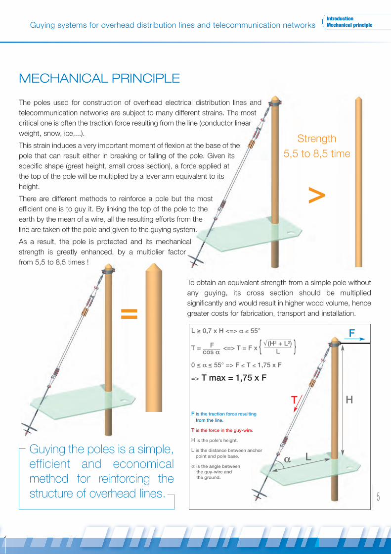
MECHANICAL PRINCIPLE
The poles used for construction of overhead electrical distribution lines and
telecommunication networks are subject to many different strains. The most
critical one is often the traction force resulting from the line (conductor linear
weight, snow, ice,...).
This strain induces a very important moment of flexion at the base of the
pole that can result either in breaking or falling of the pole. Given its
specific shape (great height, small cross section), a force applied at
the top of the pole will be multiplied by a lever arm equivalent to its
height.
There are different methods to reinforce a pole but the most
efficient one is to guy it. By linking the top of the pole to the
earth by the mean of a wire, all the resulting efforts from the
line are taken off the pole and given to the guying system.
As a result, the pole is protected and its mechanical
strength is greatly enhanced, by a multiplier factor
from 5,5 to 8,5 times !
Strength
5,5 to 8,5 time
>
Guying the poles is a simple,efficient and economicalmethod for reinforcing thestructure of overhead lines.
To obtain an equivalent strength from a simple pole without
any guying, its cross section should be multiplied
significantly and would result in higher wood volume, hence
greater costs for fabrication, transport and installation.
T
F
H
Lα
L ≥ 0,7 x H <=> α ≤ 55°
T = F <=> T = F x { }0 ≤ α ≤ 55° => F ≤ T ≤ 1,75 x F
=> T max = 1,75 x F
F is the traction force resulting from the line.
T is the force in the guy-wire.
H is the pole's height.
L is the distance between anchor point and pole base.
α is the angle between the guy-wire and the ground.
cos α LM(H2 + L2)
Haubanage ok_SICAME GROUP 07/02/13 16:47 Page5
6
Guying systems for overhead distribution lines and telecommunication networks
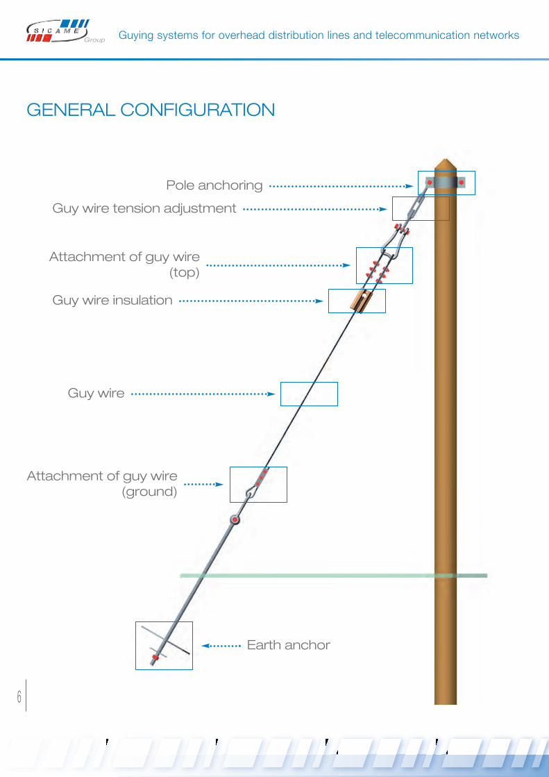
GENERAL CONFIGURATION
Pole anchoring
Guy wire tension adjustment
Guy wire insulation
Guy wire
Attachment of guy wire (top)
Attachment of guy wire (ground)
Earth anchor
Haubanage ok_SICAME GROUP 07/02/13 16:48 Page6

7
Guying systems for overhead distribution lines and telecommunication networksGeneral configurationTechnical data
TECHNICAL DATA
1. Wooden pole dimensions
Poles are designed to offer a constant strength, depending on their height. The the higher the strenght of a pole, the
bigger its diameter at the top and bottom. The available strenght corresponds to the strain applicable at pole top.
GEOMETRY OF GUYING POLE
HEIGHT (m) 7 8 9 10 11 12 13 14 15 16 17 18 19 20 21 22
Min .Ø at pole top (mm)
Min. Ø at 1 meter from pole bottom (mm)
110
155
115
165
120
175
120
185
120
190
120
200
130
210
130
215
130
225
Available strength (N) 1000
Min .Ø at pole top (mm)
Min. Ø at 1 meter from pole bottom (mm)
130
170
130
185
140
190
140
200
140
210
140
220
150
230
140
235
150
245
160
255
160
260
160
265
160
270
160
275
160
285
160
290
Available strength (N) 1400
Min .Ø at pole top (mm)
Min. Ø at 1 meter from pole bottom (mm)
145
190
150
200
155
210
155
220
155
230
155
240
165
250
165
260
165
270
170
275
170
280
170
285
180
295
180
300
180
310
180
315
Available strength (N) 1900
Min .Ø at pole top (mm)
Min. Ø at 1 meter from pole bottom (mm)
165
220
170
230
170
240
170
250
170
260
180
270
180
280
180
290
190
300
190
305
190
310
200
320
200
330
200
335
200
340
Available strength (N) 2550
Min .Ø at pole top (mm)
Min. Ø at 1 meter from pole bottom (mm)
180
235
190
250
190
260
190
270
190
280
200
290
200
300
200
310
210
320
210
330
220
335
220
345
220
355
230
365
230
370
Available strength (N) 3250
Min .Ø at pole top (mm)
Min. Ø at 1 meter from pole bottom (mm)
200
260
210
270
210
285
210
295
210
305
220
315
220
325
220
335
Available strength (N) 4300
Min .Ø at pole top (mm)
Min. Ø at 1 meter from pole bottom (mm)
220
280
230
290
230
305
235
320
235
330
245
340
245
350
250
365
Available strength (N) 5500
Haubanage ok_SICAME GROUP 07/02/13 16:48 Page7

8
Guying systems for overhead distribution lines and telecommunication networks
2. Contribution of guying
The table below shows the dimensions of guyed pole and their corresponding resulting strengths.
We can compare the available strength of a single pole with the strength of the same size of pole reinforced with
guying.
Depending on the type of installation, the guying system will increase the pole strength by 5,3 to 8,4 times.
This significant increase of strength is due to the fact that the mechanical strains are taken by the guying system
(extremly resistant to traction) instead of the pole itself.
GUYED WOODEN POLES
HEIGHT (m) 9 10 11 12 13 14 15
Min .Ø at pole top (mm)
Min. Ø at 1 meter from pole bottom (mm)
140
190
140
200
140
210
140
220
150
230
150
235
150
245
Available strength (N) 10 000 8 000
Min .Ø at pole top (mm)
Min. Ø at 1 meter from pole bottom (mm)
150
210
155
220
155
230
155
240
165
250
165
260
165
270
Available strength (N) 16 000 12 500 10 000
Min .Ø at pole top (mm)
Min. Ø at 1 meter from pole bottom (mm)
170
230
170
240
170
250
170
260
180
270
180
280
180
290
Available strength (N) 20 000 16 000
CONTRIBUTION OF GUYING
STRENGTH OF A SINGLE POLE (N) 1 400 1 900 2 550
STRENGHT OF A GUYED POLE (N)From 8 000 to 10 000
From 10 000 to 16 000
From 16 000 to 20 000
MULTIPLIER FACTOR From 5,7 to 7,1 From 5,3 to 8,4 From 6,3 to 7,8
Haubanage ok_SICAME GROUP 07/02/13 16:48 Page8
9
Guying systems for overhead distribution lines and telecommunication networksTechnical data
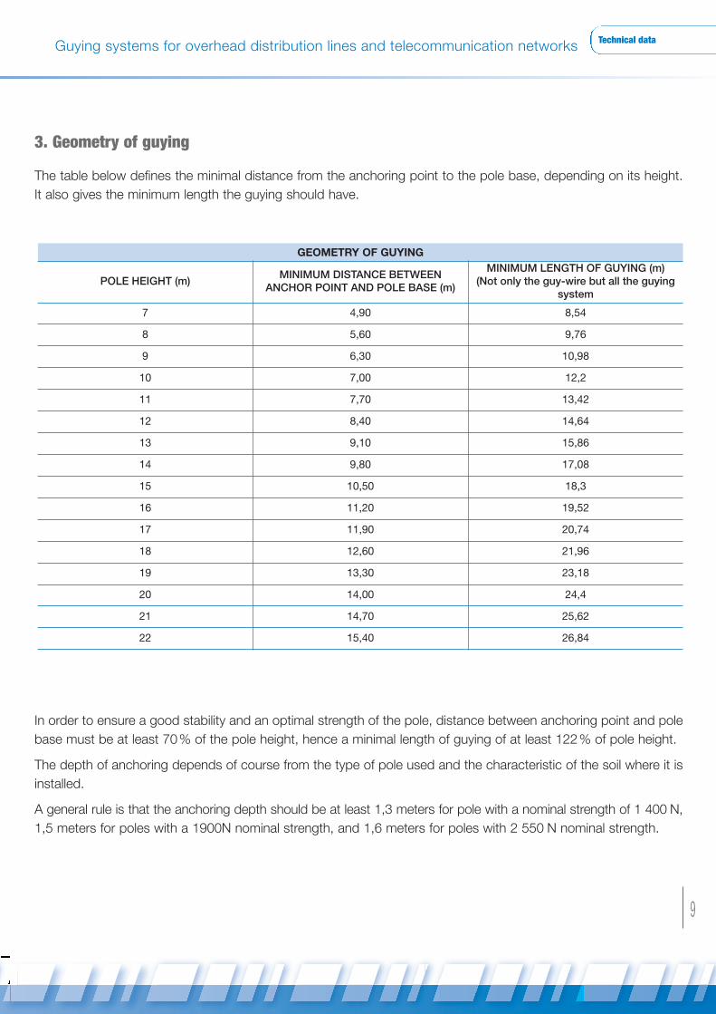
3. Geometry of guying
The table below defines the minimal distance from the anchoring point to the pole base, depending on its height.
It also gives the minimum length the guying should have.
In order to ensure a good stability and an optimal strength of the pole, distance between anchoring point and pole
base must be at least 70% of the pole height, hence a minimal length of guying of at least 122% of pole height.
The depth of anchoring depends of course from the type of pole used and the characteristic of the soil where it is
installed.
A general rule is that the anchoring depth should be at least 1,3 meters for pole with a nominal strength of 1 400 N,
1,5 meters for poles with a 1900N nominal strength, and 1,6 meters for poles with 2 550 N nominal strength.
GEOMETRY OF GUYING
POLE HEIGHT (m)MINIMUM DISTANCE BETWEEN
ANCHOR POINT AND POLE BASE (m)
MINIMUM LENGTH OF GUYING (m) (Not only the guy-wire but all the guying
system
7 4,90 8,54
8 5,60 9,76
9 6,30 10,98
10 7,00 12,2
11 7,70 13,42
12 8,40 14,64
13 9,10 15,86
14 9,80 17,08
15 10,50 18,3
16 11,20 19,52
17 11,90 20,74
18 12,60 21,96
19 13,30 23,18
20 14,00 24,4
21 14,70 25,62
22 15,40 26,84
Haubanage ok_SICAME GROUP 07/02/13 16:48 Page9
10
Guying systems for overhead distribution lines and telecommunication networks
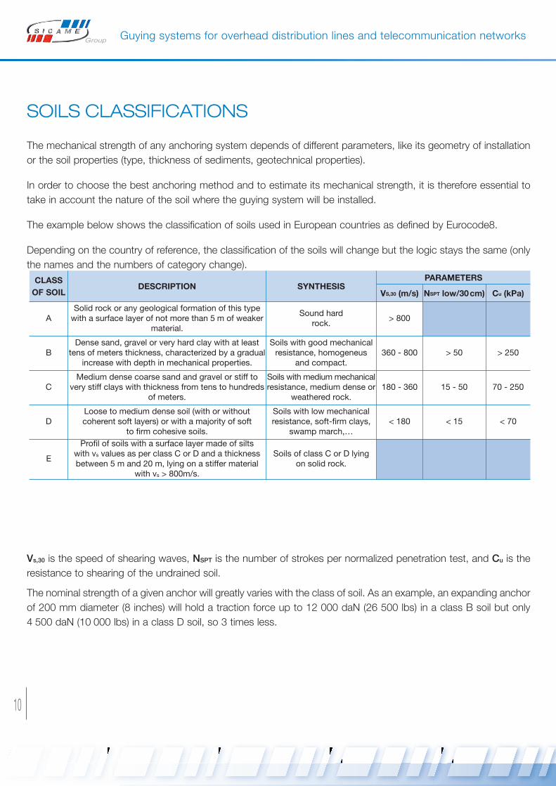
SOILS CLASSIFICATIONS
The mechanical strength of any anchoring system depends of different parameters, like its geometry of installation
or the soil properties (type, thickness of sediments, geotechnical properties).
In order to choose the best anchoring method and to estimate its mechanical strength, it is therefore essential to
take in account the nature of the soil where the guying system will be installed.
The example below shows the classification of soils used in European countries as defined by Eurocode8.
Depending on the country of reference, the classification of the soils will change but the logic stays the same (only
the names and the numbers of category change).
Vs,30 is the speed of shearing waves, NSPT is the number of strokes per normalized penetration test, and Cu is the
resistance to shearing of the undrained soil.
The nominal strength of a given anchor will greatly varies with the class of soil. As an example, an expanding anchor
of 200 mm diameter (8 inches) will hold a traction force up to 12 000 daN (26 500 lbs) in a class B soil but only
4 500 daN (10 000 lbs) in a class D soil, so 3 times less.
CLASS
OF SOILDESCRIPTION SYNTHESIS
PARAMETERS
vS,30 (m/s) NSPT low/30cm) Cu (kPa)
ASolid rock or any geological formation of this typewith a surface layer of not more than 5 m of weaker
material.
Sound hard rock.
> 800
BDense sand, gravel or very hard clay with at least
tens of meters thickness, characterized by a gradualincrease with depth in mechanical properties.
Soils with good mechanicalresistance, homogeneus
and compact.360 - 800 > 50 > 250
CMedium dense coarse sand and gravel or stiff to
very stiff clays with thickness from tens to hundredsof meters.
Soils with medium mechanicalresistance, medium dense or
weathered rock.180 - 360 15 - 50 70 - 250
DLoose to medium dense soil (with or without coherent soft layers) or with a majority of soft
to firm cohesive soils.
Soils with low mechanical resistance, soft-firm clays,
swamp march,…< 180 < 15 < 70
E
Profil of soils with a surface layer made of silts with vs values as per class C or D and a thicknessbetween 5 m and 20 m, lying on a stiffer material
with vs > 800m/s.
Soils of class C or D lying on solid rock.
Haubanage ok_SICAME GROUP 07/02/13 16:48 Page10

11
1Earthanchoring
Earth anchorThere are different anchoring methods to link the guy wire to the Earth. Each of them has its own advantages
depending on the conditions of installation and nature of the soil.
The use of a metallic sole associated with an anchor rod is a simple way of anchoring a guy wire to the earth. The
sole is directly burried into the ground with the rod attached to it, only the tip of the rod stays out to attach the guy
wire.
The sole can take all the traction strains because of its wide surface in contact with the earth.
ANCHORING METHOD ELEMENTS
1 Sole anchoringMetallic sole
Anchor rod with washer
2 Plate anchoringAnchor Plate
Anchor rod
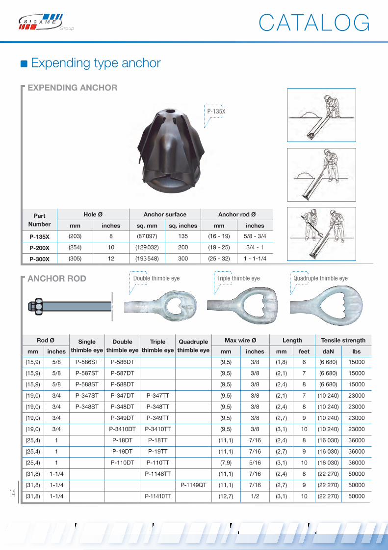
3 Expending type anchoringExpending anchor
Anchor rod
4 Log anchoringCurved washer (+ wood log)
Anchor rod
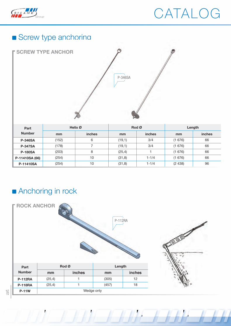
5 Screw type anchoring Screw anchor
6 Anchoring in rockRock anchor
Wedge
7 Anchor extension Anchor extension
8 Pole bearing plate Pole bearing plate
CATALOG
Haubanage ok_SICAME GROUP 07/02/13 16:49 Page11

12
Sole anchor
Part
Number
A e a b
mm inches mm inches mm inches mm inches
PA 300 300 (11.81) 6 (15/64) 28 (1.10) 50 (1.97)
PA 400 400 (15.75) 10 (25/64) 28 (1.10) 50 (1.97)
PA 600 600 (25.62) 12 (15/32) 35 (1.38) 50 (2,56)
METALLIC SOLE
PA-300
Part
Number
Ø D Length
mm inches mm inches
PA 2-31/6 200 (7.9)
PA 3-31/6 300 (11.8)
TA 31/5 1 700 (66.9)
ANCHORING SYSTEM FOR TELECOMS
Part
Number
D Ø L
mm inches mm inches mm inches
TA 20-1900 20 (25/32) 22 (55/64) 1 900 (74.8)
TA 27-2300 27 (1.06) 22 (55/64) 2 300 (90.6)
ANCHOR ROD
TA 28-2300
CATALOG
PA 2-31/6PA 3-31/6
TA 31/5
Haubanage ok_SICAME GROUP 07/02/13 16:49 Page12

13
1Earthanchoring
Plate anchoring
Part
Number
A Tensile strength Surface For rod with Ø
mm inches daN lbs sq. mm sq. inches mm inches
P-256P 406 16 7000 (15 419) (165 161) 256 (16-19) 5/8 - 3/4
P-400P 508 20 10000 (22 026) (258 064) 400 (16 - 19 - 25 - 32) 5/8 - 3/4 - 1 - 1¼
P-900PHQ 762 30 36000 (79 295) (580 644) 900 (32) 1-1/4
ANCHOR PLATE
P-400P
Rod Ø Single
thimble eye
Double
thimble eye
Triple
thimble eye
Quadruple
thimble eye
Max wire Ø Length Tensile strength
mm inches mm inches mm feet daN lbs
(15,9) 5/8 P-586ST P-586DT (9,5) 3/8 (1,8) 6 (6 680) 15000
(15,9) 5/8 P-587ST P-587DT (9,5) 3/8 (2,1) 7 (6 680) 15000
(15,9) 5/8 P-588ST P-588DT (9,5) 3/8 (2,4) 8 (6 680) 15000
(19,0) 3/4 P-347ST P-347DT P-347TT (9,5) 3/8 (2,1) 7 (10 240) 23000
(19,0) 3/4 P-348ST P-348DT P-348TT (9,5) 3/8 (2,4) 8 (10 240) 23000
(19,0) 3/4 P-349DT P-349TT (9,5) 3/8 (2,7) 9 (10 240) 23000
(19,0) 3/4 P-3410DT P-3410TT (9,5) 3/8 (3,1) 10 (10 240) 23000
(25,4) 1 P-18DT P-18TT (11,1) 7/16 (2,4) 8 (16 030) 36000
(25,4) 1 P-19DT P-19TT (11,1) 7/16 (2,7) 9 (16 030) 36000
(25,4) 1 P-110DT P-110TT (7,9) 5/16 (3,1) 10 (16 030) 36000
(31,8) 1-1/4 P-1148TT (11,1) 7/16 (2,4) 8 (22 270) 50000
(31,8) 1-1/4 P-1149QT (11,1) 7/16 (2,7) 9 (22 270) 50000
(31,8) 1-1/4 P-11410TT (12,7) 1/2 (3,1) 10 (22 270) 50000
ANCHOR ROD
CATALOG
Double thimble eye Triple thimble eye Quadruple thimble eye
Haubanage ok_SICAME GROUP 07/02/13 16:49 Page13
14
Expending type anchor
Part
Number
Hole Ø Anchor surface Anchor rod Ø
mm inches sq. mm sq. inches mm inches
P-135X (203) 8 (87097) 135 (16 - 19) 5/8 - 3/4
P-200X (254) 10 (129032) 200 (19 - 25) 3/4 - 1
P-300X (305) 12 (193548) 300 (25 - 32) 1 - 1-1/4
EXPENDING ANCHOR
P-135X
Rod Ø Single
thimble eye
Double
thimble eye
Triple
thimble eye
Quadruple
thimble eye
Max wire Ø Length Tensile strength
mm inches mm inches mm feet daN lbs
(15,9) 5/8 P-586ST P-586DT (9,5) 3/8 (1,8) 6 (6 680) 15000
(15,9) 5/8 P-587ST P-587DT (9,5) 3/8 (2,1) 7 (6 680) 15000
(15,9) 5/8 P-588ST P-588DT (9,5) 3/8 (2,4) 8 (6 680) 15000
(19,0) 3/4 P-347ST P-347DT P-347TT (9,5) 3/8 (2,1) 7 (10 240) 23000
(19,0) 3/4 P-348ST P-348DT P-348TT (9,5) 3/8 (2,4) 8 (10 240) 23000
(19,0) 3/4 P-349DT P-349TT (9,5) 3/8 (2,7) 9 (10 240) 23000
(19,0) 3/4 P-3410DT P-3410TT (9,5) 3/8 (3,1) 10 (10 240) 23000
(25,4) 1 P-18DT P-18TT (11,1) 7/16 (2,4) 8 (16 030) 36000
(25,4) 1 P-19DT P-19TT (11,1) 7/16 (2,7) 9 (16 030) 36000
(25,4) 1 P-110DT P-110TT (7,9) 5/16 (3,1) 10 (16 030) 36000
(31,8) 1-1/4 P-1148TT (11,1) 7/16 (2,4) 8 (22 270) 50000
(31,8) 1-1/4 P-1149QT (11,1) 7/16 (2,7) 9 (22 270) 50000
(31,8) 1-1/4 P-11410TT (12,7) 1/2 (3,1) 10 (22 270) 50000
ANCHOR ROD
CATALOG
Double thimble eye Triple thimble eye Quadruple thimble eye
Haubanage ok_SICAME GROUP 07/02/13 16:49 Page14

Part
Number
Dimensions Hole Ø Thickness
mm inches mm inches mm inches
P-9966CW (152 × 152) 6 × 6 (28,6) 1-1/8 (15,9) 5/8
P-9977CW (178 × 178) 7 × 7 (34,9) 1-3/8 (19,1) 3/4
15
1Earthanchoring
Log anchoring
CURvED WASHER
P-9966CW
Rod Ø Single
thimble eye
Double
thimble eye
Triple
thimble eye
Quadruple
thimble eye
Max wire Ø Length Tensile strength
mm inches mm inches mm feet daN lbs
(15,9) 5/8 P-586ST P-586DT (9,5) 3/8 (1,8) 6 (6 680) 15000
(15,9) 5/8 P-587ST P-587DT (9,5) 3/8 (2,1) 7 (6 680) 15000
(15,9) 5/8 P-588ST P-588DT (9,5) 3/8 (2,4) 8 (6 680) 15000
(19,0) 3/4 P-347ST P-347DT P-347TT (9,5) 3/8 (2,1) 7 (10 240) 23000
(19,0) 3/4 P-348ST P-348DT P-348TT (9,5) 3/8 (2,4) 8 (10 240) 23000
(19,0) 3/4 P-349DT P-349TT (9,5) 3/8 (2,7) 9 (10 240) 23000
(19,0) 3/4 P-3410DT P-3410TT (9,5) 3/8 (3,1) 10 (10 240) 23000
(25,4) 1 P-18DT P-18TT (11,1) 7/16 (2,4) 8 (16 030) 36000
(25,4) 1 P-19DT P-19TT (11,1) 7/16 (2,7) 9 (16 030) 36000
(25,4) 1 P-110DT P-110TT (7,9) 5/16 (3,1) 10 (16 030) 36000
(31,8) 1-1/4 P-1148TT (11,1) 7/16 (2,4) 8 (22 270) 50000
(31,8) 1-1/4 P-1149QT (11,1) 7/16 (2,7) 9 (22 270) 50000
(31,8) 1-1/4 P-11410TT (12,7) 1/2 (3,1) 10 (22 270) 50000
ANCHOR ROD
CATALOG
Double thimble eye Triple thimble eye Quadruple thimble eye
Haubanage ok_SICAME GROUP 07/02/13 16:49 Page15
16
Screw type anchoring
P-346SA
Part
Number
Helix Ø Rod Ø Length
mm inches mm inches mm inches
P-346SA (152) 6 (19,1) 3/4 (1 676) 66
P-347SA (178) 7 (19,1) 3/4 (1 676) 66
P-180SA (203) 8 (25,4) 1 (1 676) 66
P-11410SA (66) (254) 10 (31,8) 1-1/4 (1 676) 66
P-11410SA (254) 10 (31,8) 1-1/4 (2 438) 96
SCREW TYPE ANCHOR
Anchoring in rock
P-112RA
ROCK ANCHOR
Part
Number
Rod Ø Length
mm inches mm inches
P-112RA (25,4) 1 (305) 12
P-118RA (25,4) 1 (457) 18
P-11W Wedge only
CATALOG
Haubanage ok_SICAME GROUP 07/02/13 16:50 Page16
17
1Earthanchoring
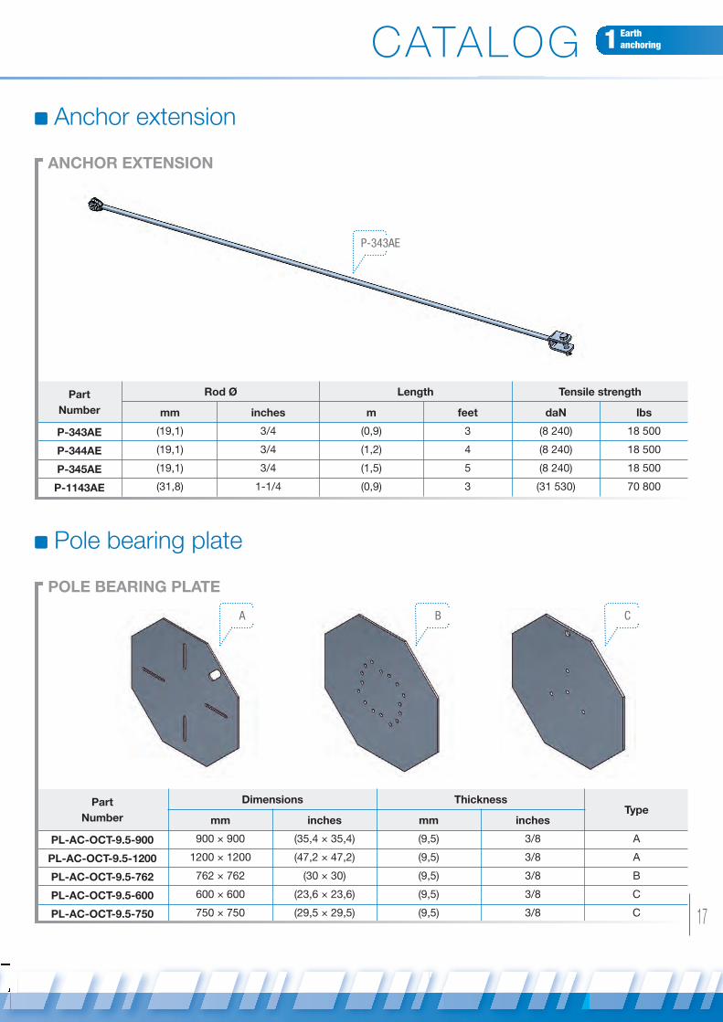
Anchor extension
P-343AE
ANCHOR EXTENSION
Part
Number
Rod Ø Length Tensile strength
mm inches m feet daN lbs
P-343AE (19,1) 3/4 (0,9) 3 (8 240) 18 500
P-344AE (19,1) 3/4 (1,2) 4 (8 240) 18 500
P-345AE (19,1) 3/4 (1,5) 5 (8 240) 18 500
P-1143AE (31,8) 1-1/4 (0,9) 3 (31 530) 70 800
Pole bearing plate
A B C
POLE BEARING PLATE
Part
Number
Dimensions ThicknessType
mm inches mm inches
PL-AC-OCT-9.5-900 900 × 900 (35,4 × 35,4) (9,5) 3/8 A
PL-AC-OCT-9.5-1200 1200 × 1200 (47,2 × 47,2) (9,5) 3/8 A
PL-AC-OCT-9.5-762 762 × 762 (30 × 30) (9,5) 3/8 B
PL-AC-OCT-9.5-600 600 × 600 (23,6 × 23,6) (9,5) 3/8 C
PL-AC-OCT-9.5-750 750 × 750 (29,5 × 29,5) (9,5) 3/8 C
CATALOG
Haubanage ok_SICAME GROUP 07/02/13 16:50 Page17

18
Part
Number
Pin Ø Opening Number of wire
accomodated
Tensile Strenght
mm inches mm inches daN lbs
M13AD 12 (15/32) 15 (19/32) 1 4 000 (8 810)
M3D 14 (35/64) 26 (1.02) 1 7 500 (16 520)
M518 20 (25/32) 35 (1-3/8) 2 12 000 (26 430)
Clevis
CLEvIS
M518
M3D M13AD
Part
Number
Pin Ø Opening Number of wire
accomodated
Tensile Strenght
mm inches mm inches daN lbs
M10-35 10 (25/64) 20 (25/32) 1 900 (1 980)
M12-45 12 (15/32) 26 1-1/32 1 1 900 (4 190)
G2130 7/16 12.5 (31/64) 19 (3/4) 1 4 000 (8 810)
CH16S 16 (5/8) 20 (25/32) 1 12 000 (26 430)
CLEvIS FOR TELECOMS
CH16S M10-35
CATALOG
Haubanage ok_SICAME GROUP 07/02/13 16:50 Page18
19
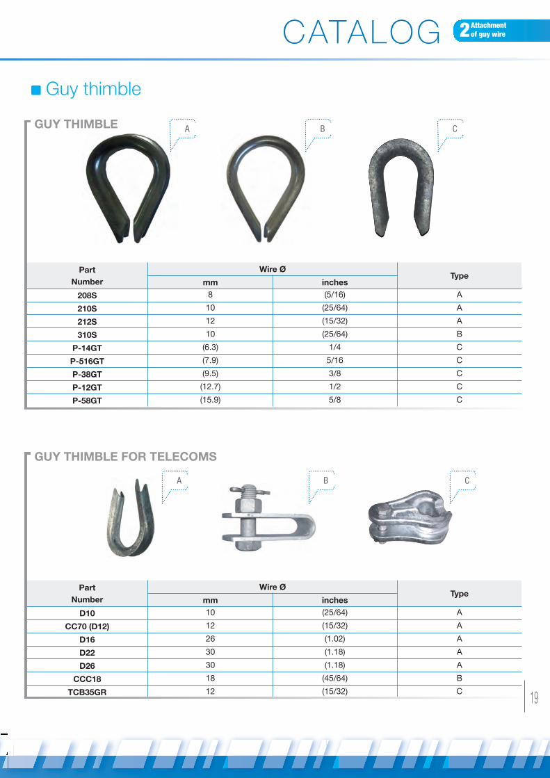
2Attachment of guy wire
Guy thimble
Part
Number
Wire ØType
mm inches
208S 8 (5/16) A
210S 10 (25/64) A
212S 12 (15/32) A
310S 10 (25/64) B
P-14GT (6.3) 1/4 C
P-516GT (7.9) 5/16 C
P-38GT (9.5) 3/8 C
P-12GT (12.7) 1/2 C
P-58GT (15.9) 5/8 C
Part
Number
Wire ØType
mm inches
D10 10 (25/64) A
CC70 (D12) 12 (15/32) A
D16 26 (1.02) A
D22 30 (1.18) A
D26 30 (1.18) A
CCC18 18 (45/64) B
TCB35GR 12 (15/32) C
GUY THIMBLE
GUY THIMBLE FOR TELECOMS
A
A B C
B C
CATALOG
Haubanage ok_SICAME GROUP 07/02/13 16:58 Page19

20
Clamp
GUY CLAMP
GUY CLAMP FOR TELECOMS
SC 2B SC 3B
Part
Number
Wire rangeType
mm inches
SC14 10 (25/64) A
P-5GC (4,7 to 9,5) 3/16 to 3/8 B
P-30GC (4,7 to 11,1) 3/16 to 7/16 B
P-50GC (7,9 to 12,7) 5/16 to 1/2 B
A B
Part
Number
Wire range Tensile strength
mm inches daN lbs
SC 2B 3 to 6 (1/8 to 15/64) 2 000 (4 410)
SC 3B 6 to 13 (15/64-33/64) 3 000 (6 610)
AUTOMATIC CLAMP
PHA 100
Part
Number
Wire range Tensile strength
mm inches daN lbs
PHA 100 10 to 11 (25/64 to 7/16) 7 000 (15 420)
CATALOG
Haubanage ok_SICAME GROUP 07/02/13 16:51 Page20

Part
Number
Wire range Length
mm inches mm inches
P-7140GE (6,3) 1/4 (635) 25
P-7516GE (7,9) 5/16 (762) 30
P-7380GE (9,5) 3/8 (889) 35
P-7716GE (11,1) 7/16 (965) 38
P-7120GE (12,7) 1/2 (1 143) 45
P-7916GE (14,3) 9/16 (1 397) 55
P-7580GE (15,9) 5/8 (1 626) 64
21
2Attachment of guy wire
AUTOMATIC CLAMP FOR TELECOMS
PHA 66270
Releasable rigid bail
Part
Number
Wire range Tensile strength
mm inches daN lbs
PHA 46 4 to 5 (5/32 to 13/64) 1 500 (3 300)
PHA 66 6 to 7 (15/64 to 9/32) 1 500 (3 300)
PREFORMED GUY GRIP
Guy Grip
CATALOG
Haubanage ok_SICAME GROUP 07/02/13 16:51 Page21

22
Guy wire
GUY CLAMP
CHA10 40P-78014GW
Part
Number
Wire ØStranding
Strand Ø Breaking Strength
mm inches mm inches daN lbs
P-78014GW (6,3) 1/4 7 (2,0) 0,08 (2 850) 6 400
CHA 6,6 (17/64) 7 2,2 (0,09) 3 080 (6 780)
P-78516GW (7,9) 5/16 7 (2,6) 0,10 (4 990) 11 200
P-78038GW (9,5) 3/8 7 (3,0) 0,12 (6 860) 15 400
CHA10 10,0 (25/64) 19 2,0 (0,08) 8 250 (18 172)
P-78716GW (11,1) 7/16 7 (3,7) 0,15 (9 260) 20 800
P-78012GW (12,7) 1/2 7 (4,2) 0,17 (11 980) 26 900
P-78058GW (15,9) 5/8 7 (5,3) 0,21 (18 880) 42 400
Guy wire protection
Part
Number
LengthColor
m feet
P-700YG (2,1) 7 Yellow
P-700GG (2,1) 7 Green
P-700YG
P-700GG
CATALOG
PLASTIC GUY GUARD
Profil
Haubanage ok_SICAME GROUP 07/02/13 16:51 Page22
23
3Guy wires / Protection /insulation
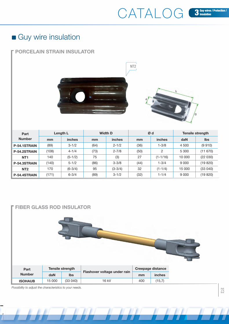
Guy wire insulation
PORCELAIN STRAIN INSULATOR
NT2
FIBER GLASS ROD INSULATOR
Part
Number
Length L Width D Ø d Tensile strength
mm inches mm inches mm inches daN lbs
P-54.1STRAIN (89) 3-1/2 (64) 2-1/2 (36) 1-3/8 4 500 (9 910)
P-54.2STRAIN (108) 4-1/4 (73) 2-7/8 (50) 2 5 300 (11 670)
NT1 140 (5-1/2) 75 (3) 27 (1-1/16) 10 000 (22 030)
P-54.3STRAIN (140) 5-1/2 (86) 3-3/8 (44) 1-3/4 9 000 (19 820)
NT2 170 (6-3/4) 95 (3-3/4) 32 (1-1/4) 15 000 (33 040)
P-54.4STRAIN (171) 6-3/4 (89) 3-1/2 (32) 1-1/4 9 000 (19 820)
Part
Number
Tensile strengthFlashover voltage under rain
Creepage distance
daN lbs mm inches
ISOHAUB 15 000 (33 040) 16 kV 400 (15,7)
Possibility to adjust the characteristics to your needs.
CATALOG
Haubanage ok_SICAME GROUP 07/02/13 16:51 Page23

24
Pole anchoring
POLE BAND
Fig.I Fig.II
Part
Number
Pole Ø Band widthType
mm inches mm inches
CA 80-135 135 (5,3) 80 (3,1) I
CA 80-165 165 (6,5) 80 (3,1) I
CA 120-200 200 (7,9) 120 (4,7) II
CA 120-240 240 (9,4) 120 (4,7) II
Part
NumberMinimum tensile strength (F)
CASHT 2 700 daN or 5 950 lbs
UNIvERSAL ANCHORING BRACKET FOR TELECOMS
30°F
CATALOG
CA 80-165
Material : galvanized steel
Material : High mechanical characteristicsaluminium alloy.
Haubanage ok_SICAME GROUP 07/02/13 16:51 Page24

25
4Pole anchoring
GUY HOOK
Part
Number
Bolts Ø Tensile Strength
mm inches daN lbs
P-1GH (15,9 to 19,1) 5/8 to 3/4 6000 (13 490)
Material : galvanized steel
Assembly with bolts
CATALOG
Haubanage ok_SICAME GROUP 07/02/13 16:52 Page25

26
ROUND EYE TO ROUND EYE
Turnbuckles
Part
Number
Rod Ø Eye Opening Stroke length Tensile Strength
mm inches mm inches mm inches daN lbs
TL 10 OO 10 (25/64) 14 (35/64) 80 (3,10) 2 000 (4 410)
TL 12 OO 12 (15/32) 19 (3/4) 100 (3,90) 3 200 (7 050)
TL 14 OO 14 (35/64) 19 (3/4) 115 (4,50) 4 000 (8 810)
TL 16 OO 16 (5/8) 24 (15/16) 130 (5,10) 5 000 (11 010)
TL 18 OO 18 (45/64) 26 (1,02) 150 (5,90) 6 500 (14 320)
TL 24 OO 24 (15/16) 28 (1,10) 185 (7,30) 13 500 (29 740)
HOOK TO ROUND EYE
Part
Number
Rod Ø Eye Opening Hook opening Stroke length Tensile Strength
mm inches mm inches mm inches mm inches daN lbs
TL 10 OC 10 (25/64) 14 (35/64) 12 (15/32) 80 (3,1) 500 (1 100)
TL 12 OC 12 (15/32) 19 (3/4) 15 (19/32) 100 (3,9) 750 (1 650)
TL 14 OC 14 (35/64) 19 (3/4) 16 (5/8) 115 (4,5) 950 (2 090)
TL 16 OC 16 (5/8) 24 (15/16) 21 (53/64) 130 (5,1) 1 200 (2 640)
CATALOG
Material : galvanized steel
Material : galvanized steel
Haubanage ok_SICAME GROUP 07/02/13 16:52 Page26

Part
Number
Rod Ø Eye Opening Tensile Strength
mm inches mm inches daN lbs
T50 10 (25/64) 15 (19/32) 360 (790)
TL 12 OC 12 (15/32) 22 (55/64) 510 (1 120)
TL 12 OO 12 (15/32) 22 (55/64) 1 600 (3 520)
Part
Number
Rod Ø Jaw opening Stroke length Tensile Strength
mm inches mm inches mm inches daN lbs
TL CC 10 to 25 (3/8 to 1) 14 to 33 (35/64-1,31) 152 to 457 (6 to 18) 2 720-22 700 6 000-50 000
27
5Guy wire tensionadjustment
JAW TO JAW
FOR TELECOMSTL 12 OC
TL 12 OO
CATALOG
Material : galvanized steel
Material : galvanized steel
Haubanage ok_SICAME GROUP 07/02/13 16:52 Page27
28
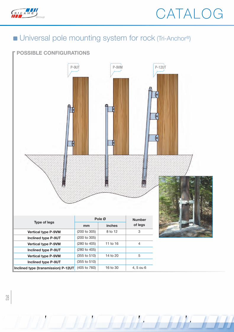
Universal pole mounting system for rock (Tri-Anchor®)
POSSIBLE CONFIGURATIONS
Type of legsPole Ø Number
of legsmm inches
vertical type P-9vM (200 to 305) 8 to 12 3
Inclined type P-9UT (200 to 305)
vertical type P-9vM (280 to 405) 11 to 16 4
Inclined type P-9UT (280 to 405)
vertical type P-9vM (355 to 510) 14 to 20 5
Inclined type P-9UT (355 to 510)
Inclined type (transmission) P-12UT (405 to 760) 16 to 30 4, 5 ou 6
P-9UT P-9VM P-12UT
CATALOG
Haubanage ok_SICAME GROUP 07/02/13 16:52 Page28

29
6Universal pole mountingsystem for rock
TRI-ANCHOR MECHANICAL STRENGTH
Pole
ØNumber
of legs
Moment on ground line to
obtain a 5 degres deflectionFailure moment on ground line
mm inches N.m ft.lbs N.m ft.lbs
(200) 8
3
(35 940) 26 460 (65 900) 48 510
(230) 9 (40 440) 29 767 (76 380) 56 228
(255) 10 (44 930) 33 075 (86 860) 63 945
(280) 11 (49 420) 36 382 (97 350) 71 663
(305) 12 (53 910) 39 690 (107 830) 79 380
(280) 11
4
(47 920) 35 280 (89 860) 66 150
(305) 12 (57 510) 42 336 (98 840) 72 765
(330) 13 (67 090) 49 392 (107 830) 79 380
(355) 14 (76 680) 56 448 (116 810) 85 995
(380) 15 (86 260) 63 504 (125 800) 92 610
(405) 16 (95 850) 70 560 (134 790) 99 225
(355) 14
5
(104 830) 77 175 (134 790) 99 225
(380) 15 (112 320) 82 687 (140 280) 103 268
(405) 16 (119 810) 88 200 (145 770) 107 310
(430) 17 (127 300) 93 712 (151 260) 111 353
(455) 18 (134 850) 99 275 (156 750) 115 395
(485) 19 (142 270) 104 737 (162 240) 119 438
(510) 20 (149 760) 110 250 (167 730) 123 480
CATALOG
Haubanage ok_SICAME GROUP 07/02/13 16:52 Page29
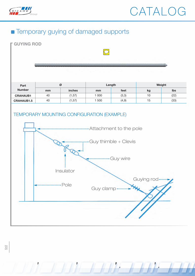
30
Temporary guying of damaged supports
TEMPORARY MOUNTING CONFIGURATION (EXAMPLE)
GUYING ROD
Part
Number
Ø Length Weight
mm inches mm feet kg lbs
CRAHAUB1 40 (1,57) 1 000 (3,3) 10 (22)
CRAHAUB1.5 40 (1,57) 1 500 (4,9) 15 (33)
Attachment to the pole
Guy thimble + Clevis
Guy wire
PoleGuy clamp
Guying rod
Insulator
CATALOG
Haubanage ok_SICAME GROUP 07/02/13 16:53 Page30

31
7Temporary guyingCATALOG
www.sicame.com
Companies worldwide at the service of mankind
ENERGY TRANSMISSIO
NN
ETWO
RKS
UNDERGROUNDD
ISTRIB
UTIO
NN
ETW
ORKS
ELECTRICAL SAFETY&
PR
OTEC
TION
OVERHEAD LINED
ISTRIB
UTIO
NN
ETW
ORKS COMPRESSIONTO
OLS
&TER
MIN
ATIONS
Haubanage ok_SICAME GROUP 07/02/13 16:53 Page31
32
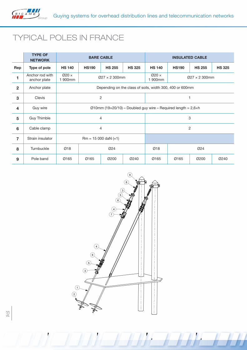
Guying systems for overhead distribution lines and telecommunication networks
TYPICAL POLES IN FRANCE
TYPE OF
NETWORKBARE CABLE INSULATED CABLE
Rep Type of pole HS 140 HS190 HS 255 HS 325 HS 140 HS190 HS 255 HS 325
1Anchor rod withanchor plate
Ø20 ×1 900mm
Ø27 × 2 300mmØ20 ×
1 900mmØ27 × 2 300mm
2 Anchor plate Depending on the class of soils, width 300, 400 or 600mm
3 Clevis 2 1
4 Guy wire Ø10mm (19×20/10) – Doubled guy wire – Required length = 2,6×h
5 Guy Thimble 4 3
6 Cable clamp 4 2
7 Strain insulator Rm = 15 000 daN (×1)
8 Turnbuckle Ø18 Ø24 Ø18 Ø24
9 Pole band Ø165 Ø165 Ø200 Ø240 Ø165 Ø165 Ø200 Ø240
1
2
3
5
4
6
7
6
3
5
8
9
4
Haubanage ok_SICAME GROUP 07/02/13 16:53 Page32
33
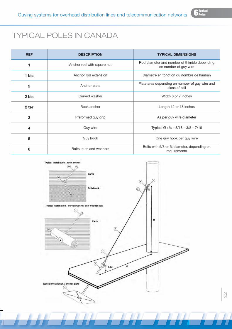
Guying systems for overhead distribution lines and telecommunication networksIntroduction Mechanical principle6Typical Poles
TYPICAL POLES IN CANADA
REF DESCRIPTION TYPICAL DIMENSIONS
1 Anchor rod with square nutRod diameter and number of thimble depending
on number of guy wire
1 bis Anchor rod extension Diametre en fonction du nombre de hauban
2 Anchor platePlate area depending on number of guy wire and
class of soil
2 bis Curved washer Width 6 or 7 inches
2 ter Rock anchor Length 12 or 18 inches
3 Preformed guy grip As per guy wire diameter
4 Guy wire Typical Ø : ¼ – 5/16 – 3/8 – 7/16
5 Guy hook One guy hook per guy wire
6 Bolts, nuts and washersBolts with 5/8 or ¾ diameter, depending on
requirements
Haubanage ok_SICAME GROUP 07/02/13 16:54 Page33

© 2013 SICAME GROUP.All rights of reproduction (in full or part), adaptation and translation reserved for any country.
!
This documentation is not as per agreement.Items represented are proposed while stock lasts.SICAME GROUP reserve the right to stop production
or modify specifications without prior notice.
Non-contractual pictures
Haubanage ok_SICAME GROUP 07/02/13 16:54 Page34

Haubanage ok_SICAME GROUP 07/02/13 16:54 Page35

Groupe SicameB.P. N°1 - 19231 PompadourCedex - France
Tél. : (33) 05 55 73 89 00Fax : (33) 05 55 98 53 79Email : [email protected]
www.sicame.fr
Haubanage ok_SICAME GROUP 07/02/13 16:54 Page36