Embed Size (px)
DESCRIPTION
lifting
Citation preview

LIFTINGMANUAL

Lifting operations call for a very highlevel of safety. The lifting equipment and
the way it is used are crucial to yoursafety on site. For this reason, it is
important to choose a responsible sup-plier. Gunnebo Lifting is a leading manu-
facturer of lifting equipment. When itcomes to quality we leave nothing to
chance.That is something you can rely on.
Edition 1, eng.
Regular inspection. Storage . . . . . . . . . 90-91Inspection . . . . . . . . . . . . . . . . . . . . . 92-94Chain . . . . . . . . . . . . . . . . . . . . . . . . 95-99Steel wire rope . . . . . . . . . . . . . . . . 100-102Components . . . . . . . . . . . . . . . . . . . . . 103Soft lifting equipment . . . . . . . . . . . 104-105Keeping a register . . . . . . . . . . . . . 106-107Inspection planning . . . . . . . . . . . . . 108-109Checklist for safe lifting . . . . . . . . . . . . . 110
Contents
Introduction . . . . . . . . . . . . . . . . . . . . . . . 4The ant and the elephant . . . . . . . . . . . . . . 5Standards, laws and regulations . . . . . . . 6-7Expressions and terms . . . . . . . . . . . . . . 8-9Safety and liability . . . . . . . . . . . . . . . 10-13Components of lifting equipment . . . . . 14-29
General . . . . . . . . . . . . . . . . . . . . . . . 40-65Chain . . . . . . . . . . . . . . . . . . . . . . . . 66-73Steel wire rope . . . . . . . . . . . . . . . . . . 74-83Soft lifting equipment . . . . . . . . . . . . . 84-89
Types of lifting equipment . . . . . . . . . . 30-31Load tables . . . . . . . . . . . . . . . . . . . . 32-39
Safe lifting -every time
Lifting equipment in general Page
Choosing the right equipment Page
When lifting Page
Maintenance Page
©
54
This manual is your pocket guide to the use oflifting equipment. It covers equipment made ofsynthetic fibre, steel wire rope and chain withassociated master links, hooks and couplings.
It consists of four colour-coded main partswhich can be read individually when needed:
Introduction
Gunnebo does not, however, in any way claimthat this manual covers all kinds of lifting equip-ment or all lifting situations.
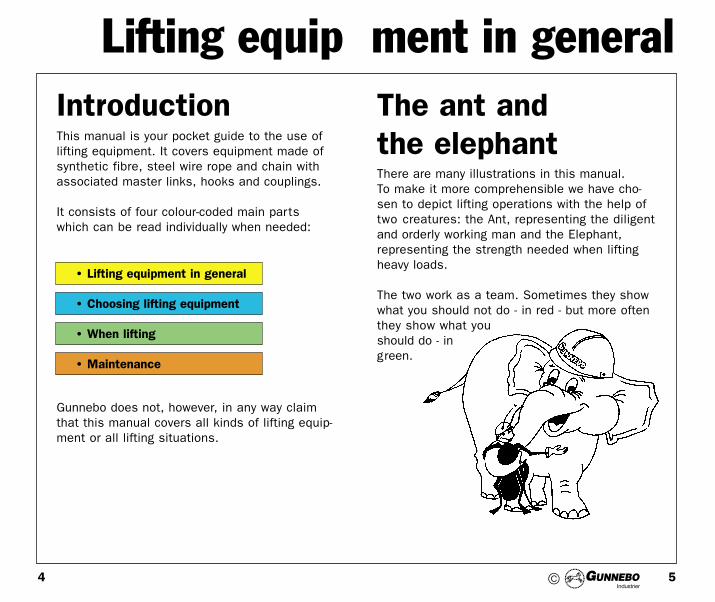
There are many illustrations in this manual.To make it more comprehensible we have cho-sen to depict lifting operations with the help oftwo creatures: the Ant, representing the diligentand orderly working man and the Elephant, representing the strength needed when liftingheavy loads.
The two work as a team. Sometimes they showwhat you should not do - in red - but more oftenthey show what youshould do - ingreen.
The ant andthe elephant
• Maintenance
• When lifting
• Choosing lifting equipment
• Lifting equipment in general
Lifting equip ment in general
©

76
Lifting equip ment in general
Several organisations are involved in thedevelopment of standards, legislation and inspection procedures in the field of lifting. We recommend that you obtain relevant informa-tion from your national Health & Safety Society.
ISO, International Standardisation Organisation,develops world-wide standards.
CEN, Comité Européen de Normalisation,develops European standards.
ASTM, American Standardisation Organizations.
Standards, lawsand regulations
©

98
Lifting equipment is everything used to connecta load to the crane hook, i. e. lifting slings,chain slings, soft slings, webbing slings, liftingbeams etc.
W.L.L (working load limit) is the maximum per-mitted load under normal (vertical) liftingconditions, given by the manufacturer.
Breaking force is the greatest force the equip-ment is exposed to during tensile strengthtesting.
Safety factor is the relationship between brea-king force and W.L.L. Note! The safety factorsfor chain, steel wire rope and soft slings differs.
Manufacturing proof force is the force to whichlifting equipment or components are tested priorto delivery.
Total ultimate elongation is the elongation of acomponent at the moment of breaking in per-cent of the original length. It is a measure oftoughness.
Effective length is the length between the load-bearing points of an unloaded lifting sling orchain sling.
Expressionsand terms
Effective length of a one-legged lifting sling withtwo components.
For endless slings both the effective length andthe circumference are stated.
Lifting equip ment in general
©

1110
The liability is on the user to be aware of theapplicable safety regulations for lifting in general,but responsibilities also rest with the supplier/manufacturer, who must:
• take responsibility for personal accidents caused by inferior equipment (so-called product
responsibility).• provide instructions for safe usage.• mark the equipment with the maximum
permitted load and the manufacturer’s designa-tion.• provide test certificate of proof loading and
declaration of conformity performed on the equipment when
called upon to doso.• use a reliable
quality assuran-ce system (ISO
9000).
Safety andliability
Product responsibilityNew and more demanding laws on productresponsibility have been adopted in the EU. If an injured person is able to prove his/her injury, a defect in the lifting equipment and a connection between the injury and the defect,the manufacturer (or importer) will be held responsible. For this reason, it is important thatthe manufacturer/importer is adequately insur-ed.
MarkingAssembled chain slings must be marked perman-ently with the following: - W.L.L and range of angles- CE marking- Individual identification mark.- Grade- Manufacturer´s name or
symbol.- Number of legs.Single-legged steel rope slings should be marked on the ferrules while soft lifting slings and straps should have marking tags.
Lifting equip ment in general
©

1312
Safety andliability
The ISO 9001 system ensures that the supplierhas documented routines for all activities whichmay influence on customer related quality. Athird part auditor continuously survey the con-formity of the quality system.
Quality assurance according to ISO 9001The demands on suppliers for quality assurancesystems, approved according to ISO 9001 aregrowing ever stronger. The following scopes ofthis international standard are available:
Lifting equip ment in general
©

1514
The above values do not apply to tempered
Chain is divided into types depending on shape ofthe link - short link (KL), mediumlength link (HL)
Chain
and long link (LL, HLC) chain. Chains are alsomade in different strength grades. Chain ofgrade 8 is the most common in lifting equip-ment. The sole exception is chain used in veryhot environments, where a chain of grade 3 is requi-red to prevent the heat treatment from beingaffected. Only use short link chain for liftingoperations.
Hot-dip galvanised Z KL 240 1 2,4 4,5 Agriculture, anchorage, generalPolished B HL 240 1 2,4 5,2 consumer use, hoisting pulleys (BL).
LL 240 1 2,4 5,8Painted red R KL 360 1 2,4 4,5 For use in hot environment
HL 360 1 2,5 5,2 (KL)LL 360 1 2,4 5,5
Painted blue A HL 500 1 2,4 4,5 Lashing, bundling, lumberingLL 500 1 2,5 5,2
Painted yellow U KL 800 1 2,5 4,0 Chain sling EN. 818-2Painted black B HL 800 1 2,5 5,0 Lifting equipment (KL), container las-hing
ML 800 1 2,5 5,0 (HL, HLC). Demanding applicationssuch
HLC 800 1 2,5 5,0 as towing (HL), fishing (ML), lumbering,
2
Components of lifting equipment
Chaingrade
Surface treatment Type Nom. min.breaking
strain(N/mm2)
Load factors: Typical applications
Maxload
Proofforce
Breakingforce
35
8
8+
Lifting equip ment in general
©

% of min. breaking force
Min. breaking force
Manufacturing proof force
Wroking load limit, safety factor 4:1
1716
Extreme temperaturesThe capacity of grade 8 and grade 8+ chainis reduced by temperature according to the following table:
Chain sling Reduction in temperature max. load
The safety factor of grade 8 and grade 8+ chainis 4:1, i.e. the max. load must not exceed onequarter of the estimated minimum breakingforce. The safety factor of grade 3 chain is4,5:1.
All chain produced by Gunnebo is proof loadedwith a force more than double the max. load,as shown in table, page 15.
Grade 8 chain for lifting fulfill EN 818 and ISO 3076.
% elongation
Stress/elongation diagramChain grade 8, and grade 8+ type KL
-40°C to +200°C 0%+200°C to +300°C 10%+300°C to 400°C 25%
0 10 20 30 40 50 60
100
110
120
90
80
70
60
50
40
30
0
10
2025
Lifting equip ment in general
©

1918
The most common designs of steel wire ropeused in lifting equipment are:
• 114-wire rope with a fibre core (diameter: approx. 3 to 8 mm)
• 216-wire rope with a fibre core (diameter: approx. 6 to 60 mm)
• 133-wire rope with a steel core, intended for hot environments.
• 265-wire rope with a steel core, intended for hot environments.
• 144-wire rope for use in shipping and disposable slings.
The nominal breaking strain of individual wires inropes must be 1770 N/mm2. The minimum wirefilling in ropes must be 0.40.
216-wireWarrington-Seale,fibre core
Filling factor F = 50%
The following formula can be used for calcula-ting the max. load in cases where wire with anon-standard design, not found in the standardtables, is used. The calculation yields the max.load on each leg, rounded off to the nearesthundred kgs, when the lifting angle is 0°.
Max. load = 0.8 x FO / n
whereFO = The minimum breaking load of the rope
according to ISO 2408.n = Safety factor of the rope, based on the
minimum breaking load.n = 5 when the rope diameter is 32 mm orless.n = 4 when the rope diameter is larger.
Steel wire rope
Lifting equip ment in general
©

2120
Location of the locking clampsThe length (h) of the loop on asteel wire rope must be atleast 15 times the ropediameter (d) when ferrulesare used, 10 times in case ofhand splicing.
Multiple legsMultilegged lifting slings may con-sist of two, three or four legs. Amaster link joins the legs at thetop. The legs of 3- and 4-leggedslings are connected intointermediate links.
Note that multilegged slingsshould be equipped withthimbles when used withsupplementary lifting equipment.
The distance between the two ferrules on liftingslings must not be less than 10 times the ropediameter (d).
The same restriction applies to splicing. The measurement is taken from the point ofeach clamp nearest the other.
Lifting equip ment in general
©

2322
RoundslingsRoundslings consist of an endless load-bearingsling made of polyester fibre, protected from dirtand wear with a single- or double-layered coverof polyester fabric. There are two types ofcovers: sideseam with double cover which give astiffer roundsling and the seamless for softer version.
Endless Webbing slingsThese webbing slings consist of a woven polyester webbing sewn into an endless loop. They can be used in the same way as round-slings but are limited to lower working loads.
Webbing slings with eyes and roundslingsstrops.A webbing sling is a woven webbing with sewneyeloops at both ends. It is often used to evenout and soften the pressure on the load.Roundsling strops may have loops too, but thestronger design with a fibre core and covermake them suitable for heavier lifts.
Material properties • Polyester is resistant to acids but not to
alkalis, e.g. ammonia and caustic soda.• The melting point is 260°C, but polyester lif-ting
equipment must not be used with loads hotter than 100°C.
• The strength is not affected by water. Water absorption is negligible.
• Note that friction and sharp edges quicklywear polyester down.• Lifting equipment in polyester have a blue
id tag.• Polypropylen• The melting point is 165°C.• Polypropylen must not be used with loads
hotter than 80°C.• Lifting equipment in polypropylen have a brown
id tag.
Safety factorRoundslings and webbing slings = 7:1 acc. to EN-standards.
Soft liftingequipment
Lifting equip ment in general
©

2524
The grade of the lifting components match thegrade of the chain (usually grade 8 or grade 8+)The size designation usually refers to the size ofthe chain with the same strength, e.g.:
G-10-8 = Coupling link, type G, suitable for10 mm chain, grade 8 (max. load 3.2 tonnes)
Examples of the most common mechanical couplings are shown below. For chain there areseveral alternative connection systems: G-coupling link, Berglok, the SK-system anddirect connection to clevis-type hooks.
Lifting components
Coupling link, type G Berglok chain coupler,type BL
A foolproof assem-bly system in com-bination with mat-
ching links andhooks.
Roundsling coupling,type SKR
For use with mat-ching SK-system components.
Webbing sling connec-tor, type BD
Can be disassembled. Forconnecting webbingto an end fitting ordirectly to a cranehook.
Bow shackle
Grade 8 or grade 3.
Half link, type SKT
For use with mat-ching SK-systemcomponents.
Dee shackle
Grade 8 or grade 3.
Master links can be entirely forged or be weldedfrom round steel. There are two basic designs:- single master link, for one- and two-legged
lifting slings- master link, with two sub links for three- and
four-legged lifting slings.
Master links
Master link, typeOTF or MTCFor use with Berglokchain couplers
Master link,type O or M
Master link, type OFor MFFor use with Berglokchain couplers
Master link,type OT or MT
Couplings
Lifting equip ment in general
©

2726
For steel wire rope and chain (G-couplinglink/Berglok)
Safety hook,type BK/OBK
Will notopen whenunderdirect loadand pre-
vents the hookfrom catchingwhen lifting.
Sling hook,type OKN
With latch to pre-vent unintentionalunloading.
Sling hook,type OK
Suitable when lat-ching hooks can-not be used.
Foundry hook,type OKE
With awideope-ning, to
acceptlarge diameter
Swivel safetyhook, type BKL
With aswivellingeye to
enablerotation.
Swivel latchhook, type LKN
With a swi-velling eyeto enable
rotation
Shorteninghook, type
OKF
Grab hook,type OG
No loadderating.
Not for use with Berglok. No load derating.
Supporting bridge pre-vents chain deformation.
Clevis-type hooks for direct connection to chain
Sling hook,type GKN
With latchto preventuninten-
tionalunloa-ding.
Sling hook,type GK
Suitablewhen lat-ching
hookscannotbe
used.
Safety hook,type BKG/GBK
Will not openunder direct
load andpreventsthe hookfrom cat-
ching when lifting.
Clevis swivelsafetyhook,type BKH
Especiallyfor chainhoists.
With ball bearingto enable rotation.
Grab hook,type GG
Shorteninghook withsuppor-ting brid-
ge to preventdeformation of theload bearing link.No load derating.
Sling hook,type GC
C-hook,designedto pre-vent theload from
becoming displa-ced during lifting.
Roller-bearingswivel,type SKLIUsed to insulate thelifted load to enablesafe welding. Max.1000 V. Lubricated,sealed and fullyrotational even atmaximum load.
Sling hookwith
latch,typeSKN,
without latch,type SKH
Master link,closed typeSKG, opentype SKO
Hooks
SK-System
Safety hook,type BKB
Especially for webbing
slings(also sui-table forchains
and steel ropes).
Lifting equip ment in general
©

2928
Along with ferrules, the most commoncomponents, for assembling steel wire ropeslings.
Much lifting equipment and components aremade for specific load types, e.g.:
• Custom-made lifting beam• Pallet forks• Steel plate clamps• Drum lifters etc.
Steel ropecomponents forlifting equipment
Thimble
Clamping thimbleSteel ropeclamp
Crimping ferrule Crimping ferrule
Straight Talurit ferrule Conical TK ferrule (also avai-lable with inspection hole,TKH clamp)
Crimping ferrule
Straight ultragrip
Crimping ferrule
Conical K ferrule
Special liftingequipment
Lifting equip ment in general
©
3130
Choosing equipment
Check the list below every time you are facing anew lifting situation.
Checklist• Make a good estimate of the lifting and
transportation requirements.• Find out the weight of the load.• Choose appropriate lifting equipment.• Decide the best way to attach the lifting
equipment to the load, considering its centre of gravity and configuration.
• Choose appropriate lifting equipment with sufficient capacity. Note that the sling leg loadings rise as the angle between the sling legs increases.
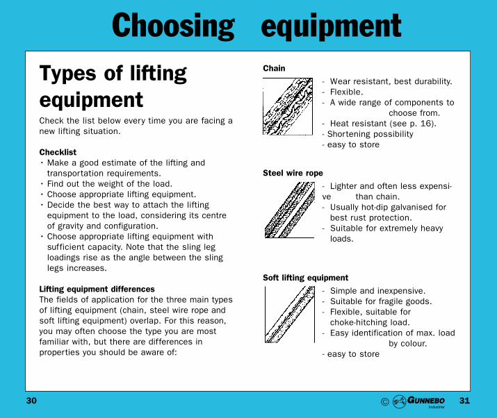
Lifting equipment differencesThe fields of application for the three main typesof lifting equipment (chain, steel wire rope andsoft lifting equipment) overlap. For this reason,you may often choose the type you are most familiar with, but there are differences in properties you should be aware of:
Types of liftingequipment
- Simple and inexpensive.- Suitable for fragile goods.- Flexible, suitable for
choke-hitching load.- Easy identification of max. load
by colour.- easy to store
Chain
- Wear resistant, best durability.- Flexible.- A wide range of components to
choose from.- Heat resistant (see p. 16).- Shortening possibility- easy to store
Steel wire rope
- Lighter and often less expensi-ve than chain.- Usually hot-dip galvanised for
best rust protection.- Suitable for extremely heavy
loads.
Soft lifting equipment
©

3332
Choosing equipmentLoad tablefor chain slings
Working Load Limits in tonnesfor chain slings grade 8, according to EN 818-4
The above loads apply to normal usage and equally loaded legs.
Asymmetric loadingIn the case of asymmetric loading, the multileg-ged chainsling should be rated at half it´s mar-ked W.L.L. or consult competent person.
1-leg 2-leg 3-legged Chokedendless sling
4-legged
Chain dim. __________ ß 0-45° ß 45-60° ß 0-45° ß 45-60° ___________
(mm) a 0-90° a 90-120° a 0-90° a 90-120°
6 1,12 1,6 1,12 2,36 1,7 1,87 1,5 2,12 1,5 3,15 2,24 2,58 2,0 2,8 2,0 4,25 3,0 3,15
10 3,15 4,25 3,15 6,7 4,75 5,013 5,3 7,5 5,3 11,2 8,0 8,516 8,0 11,2 8,0 17,0 11,8 12,5
19 11,2 16,0 11,2 23,6 17,0 18,022 15,0 21,2 15,0 31,5 22,4 23,626 21,2 30,0 21,2 45,0 31,5 33,5
32 31,5 45,0 31,5 67,0 47,5 50,0
©

3534
Choosing equipmentLoad table forsteel wire rope
The table below shows the maximum permittedload for the most common steel rope slings, tensile grade 1770 N/mm2 . Calculations arebased on ISO 2408. Recommendations for asym-metric loading conditions are the same as forchain, see pages 32-33.
5 0,25 0,35 0,25 0,5 0,4 0,5 0,4 0,20 0,5 1,06 0,35 0,5 0,35 0,7 0,5 0,7 0,5 0,32 0,8 1,67 0,5 0,7 0,5 0,95 0,75 0,95 0,75 0,40 1,0 2,08 0,6 0,8 0,6 1,0 0,9 1,0 0,9 0,48 1,2 2,69 0,75 1,1 0,75 1,6 1,1 1,6 1,1 0,6 1,5 3,010 1,0 1,4 1,0 2,1 1,5 2,1 1,5 0,8 2,0 4,012 1,5 2,1 1,5 3,1 2,2 3,1 2,2 1,2 3,0 6,014 2,0 2,8 2,0 4,2 3,0 4,2 3,0 1,6 4,0 8,016 2,5 3,5 2,5 5,2 3,7 5,2 3,7 2,0 5,0 10,018 3,0 4,2 3,0 6,3 4,5 6,3 4,5 2,4 6,0 12,020 4,0 5,6 4,0 8,4 6,0 8,4 6,0 3,2 8,0 16,022 5,0 7,0 5,0 10,5 7,5 10,5 7,5 4,0 10,0 20,024 6,0 8,0 6,0 12,0 9,0 12,0 9,0 4,8 12,0 24,026 7,0 10,0 7,0 15,0 10,0 15,0 10,0 5,6 14,0 28,028 8,0 11,0 8,0 17,0 12,0 17,0 12,0 6,4 16,0 32,032 10,0 14,0 10,0 21,0 15,0 21,0 15,0 8,0 20,0 40,036 15,0 21,0 15,0 31,0 22,0 31,0 22,0 12,0 30,0 60,040 20,0 28,0 20,0 42,0 30,0 42,0 30,0 16,0 40,0 80,044 25,0 35,0 25,0 52,0 37,0 52,0 37,0 20,0 50,0 100,048 30,0 42,0 30,0 63,0 45,0 63,0 45,0 24,0 60,0 120,052 35,0 49,0 35,0 73,0 52,0 73,0 52,0 28,0 70,0 140,056 40,0 56,0 40,0 84,0 60,0 84,0 60,0 32,0 80,0 160,060 45,0 63,0 45,0 94,0 67,0 94,0 67,0 36,0 90,0 180,0
Nom. dia-meter(mm)
(toleran-ce: +4%to -1%)
Max. load in tonnes
1-legged 2-legged 3-legged 4-legged choked endless doubleendless0-90° 0-90° 0-90°90-120° 90-120° 90-120°
©
3736
Choosing equipmentFactor
Number of legs
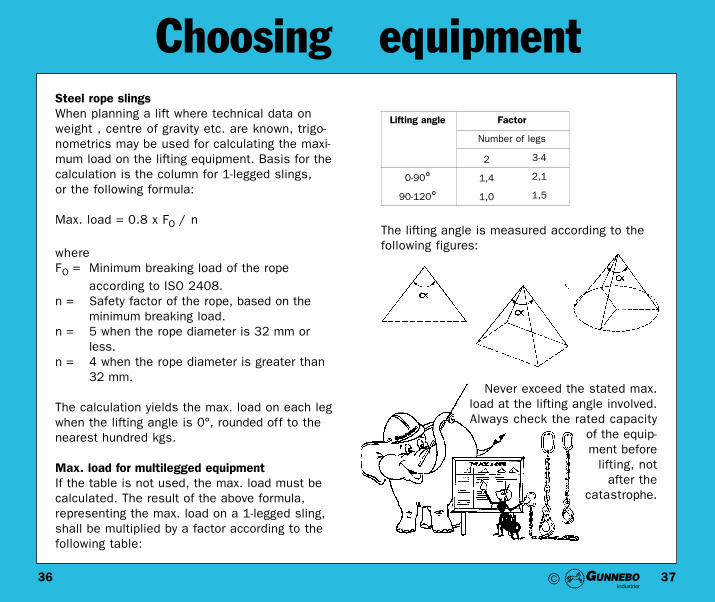
Steel rope slingsWhen planning a lift where technical data onweight , centre of gravity etc. are known, trigo-nometrics may be used for calculating the maxi-mum load on the lifting equipment. Basis for the calculation is the column for 1-legged slings, or the following formula:
Max. load = 0.8 x FO / n
whereFO = Minimum breaking load of the rope
according to ISO 2408.n = Safety factor of the rope, based on the
minimum breaking load.n = 5 when the rope diameter is 32 mm or
less.n = 4 when the rope diameter is greater than
32 mm.
The calculation yields the max. load on each legwhen the lifting angle is 0°, rounded off to thenearest hundred kgs.
Max. load for multilegged equipmentIf the table is not used, the max. load must becalculated. The result of the above formula, representing the max. load on a 1-legged sling,shall be multiplied by a factor according to the following table:
The lifting angle is measured according to the following figures:
Never exceed the stated max.load at the lifting angle involved.Always check the rated capacity
of the equip-ment before
lifting, notafter the
catastrophe.
Lifting angle
2
1,4
1,0
3-4
2,1
1,5
0-90°
90-120°
©
3938
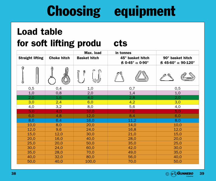
Choosing equipmentLoad tablefor soft lifting produ cts
0,5 0,4 1,0 0,7 0,51,0 0,8 2,0 1,4 1,02,0 1,6 4,0 2,8 2,03,0 2,4 6,0 4,2 3,04,0 3,2 8,0 5,6 4,05,0 4,0 10,0 7,0 5,06,0 4,8 12,0 8,4 6,08,0 6,4 16,0 11,2 8,010,0 8,0 20,0 14,0 10,012,0 9,6 24,0 16,8 12,015,0 12,0 30,0 21,0 15,020,0 16,0 40,0 28,0 20,025,0 20,0 50,0 35,0 25,030,0 24,0 60,0 42,0 30,035,0 28,0 70,0 49,0 35,040,0 32,0 80,0 56,0 40,050,0 40,0 100,0 70,0 50,0
Max. load in tonnes Straight lifting Choke hitch Basket hitch 45° basket hitch
ß 0-45° a 0-90°90° basket hitch
ß 45-60° a 90-120°
©

4140
When lifting General
Never stand under the suspendedload. People within the workingarea of the lifting equipment mustnot be exposed to danger whenthe load is lifted or moved.
Do not ride on the load.
©

4342
When lifting General
Be careful where you stand in relation to the load when lifting.The load might slip and cause injury. Keep your back clear.
Lift vertically. Otherwise the loadwill swing horizontally when clearing the ground.
©

4544
When lifting General
Avoid snatch loading. Do not expose the equipment to unnecessary strain, for examplesudden jerks.
Never use lifting equipment fordragging goods.
©

4746
When lifting GeneralTreat chain with care. Do not pullit clear from under the load wit-hout using spacers. The chain can easily become damaged and aweakened chain might break nexttime you use it.
Always position the load in a waythat makes it possible to removethe lifting equipmentwithoutusing force.
Avoid choke-hitching, as loadscan tip over.
©
4948
When lifting General
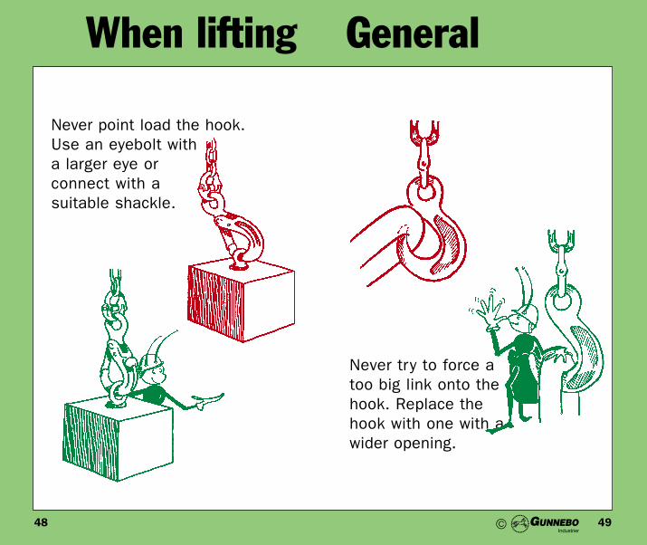
Never point load the hook. Use an eyebolt witha larger eye orconnect with a suitable shackle.
Never try to force atoo big link onto thehook. Replace thehook with one with awider opening.
©
5150
When lifting General
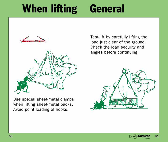
Use special sheet-metal clampswhen lifting sheet-metal packs.Avoid point loading of hooks.
Test-lift by carefully lifting theload just clear of the ground.Check the load security andangles before continuing.
©

5352
When lifting General
Handle the load with care. Lowerit gently to avoid jerks.
Grip the hook by its sideswith your fingertips only,
never with your entire hand.Otherwise your fingers might get crushed.
©

5554
When lifting General
When connecting to lifting eyes,make sure that the hooks/eyesare turned the right way (pointingout).
Do not load the hook sideways.
©

5756
When lifting General
Make sure that the load is distri-buted as evenly as possible.
Never lift with ropes or bands usedfor wrapping. They are only intended for keeping the goodstogether, not for lifting.
©

5958
When lifting General
Note that the pressure increasesas the lifting angle grows. Usethe pressure correctly.
Correct usage of pressure.
©

6160
When lifting General
Use a spreader beam. When usingbasked slings, make an extra turnaround the load to get a firm hold.
Use a steering rope tocontrol rotation when lif-
ting long goods.
©

6362
When lifting General
Goods consisting of separate partsshould be secured by wrapping thelifting sling(s) around twice toprevent the load from falling apart.
The top angle of a multi-legged lifting sling should never exceed120°. Use edge protection if thereare sharp edges. When choke-hitching, reduce the max. load by 20%.
Max 120°
©

6564
When lifting General
Wrong alignment causes excessivestrain on this shackle when lifting or pulling.
Correct alignment.
©

6766
When lifting Chain
Never knot chains. Never repairchains with bolts. Never twistchains.
A chain is never stronger than itsweakest link. Do not repair brokenchains with wires, bolts or by welding. Replacethe entire damagedchain length.
©

6968
When lifting Chain
When welding or cutting, makesure that the lifting equipment isnot affected by the heat involved,as it can damage the heat treatment of the chain.
Do not handle chain violently,especially not when strained.
©

7170
When lifting Chain
Use edge protection toprevent sharp edges from damaging the lifting equipment.
Use shortening hooks when liftingasymmetric loads.Avoid lopsided lifting.
©

7372
When lifting Chain
Do not connect directly to thechain by forcing a link onto thehook. Always use a master link.
Never lift with a twisted chain.
©

7574
When lifting Steel wire rope
Never join wire rope slings by knotting, always use a shackle.
6d = 100%5d = 85%4d = 80%3d = 70%2d = 65%1d = 50%
The strength of steel wire rope isreduced by bending. The deratingis related to the diameter of thebend as follows (d = diameter ofthe steel rope):
©

7776
When lifting Steel wire rope
Use protective gloves when handling steel wire rope.
Never shorten steel rope by knotting.
©

7978
When lifting Steel wire rope
Do not wind the rope around adouble hook to preventslipping. The bendingwill be too sharp andcause damage to therope.
Use a spacer to prevent the ropesfrom sliding. Avoid sharp bending of the rope. The load can slip if the lifting points slide. Sharp bending damages the rope.
©

8180
When lifting Steel wire rope
Bending like this willimmediately destroy the
rope. Use lifting slingswith hooks instead.
A two-legged liftingsling with a singleferrule fitted likethis can be lethal.The tearing force atthe clamp growswith the liftingangle.
©

8382
When lifting Steel wire rope
Do not expose steel wire rope toexcessive heat.Rope with fibre core: max. 100°CRope with steel core: max. 250°C Use edge protection to prevent
sharp edges from damaging the lifting equipment.
©

8584
When lifting Soft equipment
Use hooks with rounded edgesand an inner radius not less thanthe webbing width.
Lift vertically and use protectivesleeving and/or edge protectionto keep the equipment fromdirectly contacting sharp cornersand edges.
©

8786
When lifting Soft equipment
Polyester lifting strops and slingsare made of synthetic fibre andmust not be used with loads hot-ter than 100°C. Hotter goodsrequire the use of steel rope orchain.
Keep soft lifting equipment awayfrom alkalis such as caustic sodaand ammonia. The colour fadesand the slings dissolve.
©

8988
When lifting Soft equipment
Do not shorten soft lifting slingsby knotting. They quickly weaken.Avoid overloading.
Note that the max. load ofroundslings in connection
with choke or baskethitching assu-mes vertical legs(see table on
p. 38-39).
If the load is pla-ced inside theroundslingshould the maxload be calcula-ted as straightlifting (seetable on p. 38-39).
©

9190
Maintenance
Lifting equipment must be checked on a continu-al basis and be inspected yearly in accordancewith standards and industrial safety legislation.The responsibility for carrying this out rests withthe site management.
Regular inspection includes functional checks,as well as the adjustments and maintenancethat may be required from time to time.
Inspections must be carried out by people possessing sufficient knowledge of design, useand maintenance of lifting equipment.
Damaged or worn equipment must be reportedto the site management, who in turn, mustarrange for the equipment to be taken out ofuse and then be repaired or replaced.
Lifting equipment having been stored for a peri-od of time must be inspected before being takenback into use.
In addition to regular inspection, which must bethoroughly recorded, everyone working with lif-ting equipment must be on guard and inspectthe equipment before every use.
Regular inspection StorageDragging or dropping the equipment can causedamage and should be avoided.
Arrange for appropriate storage, preferably at aneven temperature.Good storagepreserves the equipment andhelps you find whatyou need faster.
Chain and steelwire rope storedfor long timesshould be rustprotected.
Soft slings and strops shouldnot be exposed to bright sun-light for any longer periods of
time. Choose a storagelocation accordingly.
©

9392
Maintenance
Lifting equipment must be inspected regularly.Good lighting without shadows is necessaryduring inspection.
CheckCheck / inspect the equipment regularly. Makesure that repairs are made when needed.
When inspecting soft lifting slings or strops: putthe equipment, stretched to its full length, on atable. Turn eyes on the equipment inside out andinspect for wear or damage. Inspect webbingone side at a time. When inspecting endlessslings it is recommended to run them around arevolving pin, or similar.
Inspection
©

9594
Before inspecting a chain it must be thoroughlycleaned of dirt and oil. All cleaning methodsthat do not damage the basic material areacceptable. No methods that cause hydrogenembrittlement or overheating are allowed, normethods that remove basic material or movematerial in a way that might hide cracks orother visible damage.
ChainThe illustration below, showing the distributionof strain in a link, can be of guidance for deci-sions on chain wear and damage.
The stress distribution in the link is very favourable.
Tensile stresses are the most important to chainstrength. They are concentrated to the most protected areas of the link: the outside of theshort side and the inside of the long side.
The relatively harmless compressive stressesare distributed the other way around, i.e. wherelink wear is at its maximum. Here the link canwear down significantly without any significanteffect on chain strength.
Keeping strain distribution in mind, we shalltake a look at a few examples of wear anddamage on the following pages.
Compressive stressTensile stress
Maintenance
©

9796
Chain showing cracks and cavities must be discarded. Transversal cracks are the mostserious.
DeformationA chain becomes permanently twis-
ted when it is overloaded in atwisted state. Such a chainmust be replaced.
Cracks / cavities
Chain containing bent links must be replaced.
Maintenance
©

9998
WearInter-link wear, as measured by taking the dia-meter indicated (d1) and one at right angles, (d2)may be tolerated until the mean of these diame-ters has been reduced to 90% of the nominaldia-meter (dn) (see figure) provided.
ElongationOverloaded equipment must bediscarded. Permanent elongation is not permitted.
If the lengths of the legs of a multi-legged chain sling are unequal, overload can be suspected
The chain must be slackened andthe adjoining links pushed backto allow inspection of the con-tact surfaces of each link.
Maintenance
d1+d2
2> 0,9dn
©

101100
RustRemember that even galva-nised steelwire ropemay rust.Bend the ropeto expose theinner strands toinspection.
Steel wire rope
Effects ofshock loading
A load applied orrelieved quickly
(shock) can damage a steel
wire rope as theadjacent picture shows.
Such a rope must be discarded.
Broken wiresBroken wires weaken the rope and causes handdamage.
The correct way to remove abroken wire is to wag it backand forth until it breaks. Do not use pliers.
Maintenance
©

103102
Ropes with kins; excessive broken wires ordamaged ferrules must be taken out of service.
ComponentsCheck the function of hooks latches, locking pinson coupling links etc.
- Check hooks thoroughly for widened apertures,which indicate abnormal loading.
- The increase in hook aperture must notexceed 10%.- No elongation is permitted for coupling
components, such as G-links, master links andBerglok links.
- Wear must not exceed 10%.- Examine all lifting components thoroughly for
transversal cracks, wear and other damage.
Maintenance
©

105104
Discard the equipment if a load bearing cord isbroken. Repair protective sleeving when needed.Cut discarded slings and straps immediately.
Soft liftingequipment
The sleeving has been torn apart bydragged along a rough surface. Theload bearing cord is intact. Let themanufacturer repair the sling or discard it.
A cut as a result of sharp edgescombined with heavy loads in movement. A load bearing cord isbroken. Discard the sling.
Webbing slings and straps
The warp is split as a result oflopsided loading. The strength is notaffected unless the warp is broken.The equipment can be repaired bythe manufacturer or be discarded.
A hardened, shiny surface is asign of damage caused by severefriction. Webbing can easilyslide, causing friction, when thelifting angle is wide. Folding thewebbing at the damage makes it easier to seethe extent of it. If the damage is wider than 5% ofthe webbing width the equipment must be discarded.
Round slings
Maintenance
©

107106
Keeping a registerKeeping a proper register is important to safe lifting. The register must describe the equipmentand list its identity markings.
Intervals for inspection and testing should bedetermined and entered into the register.
The condition of the equipment and all testresults must be recorded after every inspection.The reason for, and a description of, every repairmust also be recorded.
The register is intended as a continuous description, ensuring that the equipment is properly inspected, tested and maintained andthat it is currently in a good condition for use.
Maintenance
©

109108
Inspection planning1. Master linksMaterial wear must not exceed 10%. Permanentelongation is not permitted. File away sharpcuts and burrs. Note: In case of bad deformationthe link must be discarded.
2. Coupling linksMaterial wear must not exceed 10%. Permanentelongation is not permitted. File away sharpcuts and burrs. Failure to pivot is a sign of pre-vious overload. Make sure that the load pin islocked in position and that the locking pins (BL)securely lock the load pin.
3. ChainMaterial wear must not exceed 10%. Wear is defined as the reduction in average diameter ofthe chain material, measured in two transversaldirections. Permanent chain elongation is not permitted.File away sharp cuts and burrs.
4. HooksMaterial wear must not exceed 10%. Themaximum permissible increase in hook openingdue to wear is 10%. File away sharp cuts andburrs.
5. Steel wire ropeSteel wire rope with kinks, excessive brokenwires or damaged ferrules must be discarded.When wire breakage adds up to half a strand, the rope must be discarded. Note that steel wirerope may rust from the inside. Bend the rope to expose the inner strands to inspection.
6. Round slings / Webbing slings and strapsRoundslings: When holes in the protective sleeving expose the load-bearingfibres to dirt, the sling should bediscarded. If there are holes in thesleeving and broken load-bearingcords, the sling must be discar-ded. Roundslings must also be examined by hand for lumps, indicating fibre breakage.
Webbing slings and strops: If there is damage from friction,the equipment must be discar-ded. If eye sleeving is worn out: discard or repair. If edge damageexceeds 5% of the webbing width, the equipment must be discarded. Check that the seams are intact.
Maintenance
©

111110
Check-list forsafe lifting• Confirm the weight.
• Choose on a lifting method
• Consider all the angles
• Choose suitable equipment
• Attach the load and check:- the centre of gravity- if there is a risk of rotation- if there is a risk of sliding- that the load will keep together
• Position yourself - keep your back clear
• Test-lift until the load just clears the ground. Then check the load distribution.
• Never drag the load with the equipment
• Take note of the max. load. Never overload
Notes
Maintenance
©

113112 ©

115114
More information?Export sales / Production
Gunnebo Industrier ABBusiness Unit LiftingP.O. Box 44S-730 60 Ramnäs
Tel: +46 (0)220 384 00Fax: +46 (0)220 384 98
Web page: www.gunnebolifting.comE-mail: [email protected]
Dealer:
Copyright Gunnebo Industrier AB
©

R700.E August 2001