Embed Size (px)
Citation preview

Gulf Coast Carbon CenterIndustry-Academic Research Partnership
Assessment of options for carbon capture and sequestrationin an area of large sources and large geologic capacity

Geologic Sequestration Emplaces Dense-Phase
CO2 in Pore Systems in Rock To reduce CO2 emissionsto air from point sources..
Carbon extractedfrom a coal or otherfossil fuel…
is currently burned and emitted to air
CO2 is captured as concentratedhigh pressure fluid by one of severalmethods..
CO2 is shipped as dense-phase fluid via pipeline to a selected, permitted injection site
CO2 injected at pressure intopore space at depths below and isolated (sequestered)from potable water.
CO2 stored in pore space over geologicallysignificant time frames.

Who is the Gulf Coast Carbon Center?Who is the Gulf Coast Carbon Center?
New Members Sempra, Shell, TXU
Fayette Power Plant (LCRA/Austin Energy)
Industry Sponsors Hosted by:
Staff

Gulf Coast Carbon Center Collaborations
• DOE funded Southeast Regional Carbon Sequestration Partnership (SECARB) led by Southern States Energy Board– $4.9 M Phase II “Stacked Storage” = EOR+Brine
storage– $35M “early” demonstration with Denbury Resources
Cranfield Mississippi– Sponsored projects –SE US power companies
• DOE funded Southwest Regional Carbon Sequestration Partnership (SWCARB) led by New Mexico Tech– Project at SACROC hosted by KinderMorgen

GCCC Strategic Plan 2007-GCCC Strategic Plan 2007-20102010
GCCC Strategic Plan 2007-GCCC Strategic Plan 2007-20102010Goal 1: To educate the next generation of carbon
management professionals and regulatorsGoal 2: To develop selection criteria for commercial CO2 sequestration sitesGoal 3: To define an adequate and reliable monitoring and verification strategy applicable to long term storage Goal 4: Evaluation of sources risk and liability potentially associated with CO2 sequestrationGoal 5: Evaluation of economic potential of CO2 to enhance oil and gas recovery in the Gulf CoastGoal 6: Development of market framework and economic models for CO2 capture and storage in the Gulf CoastGoal 7: GCCC service and training to partners

Goal 1: Educate the Next Generation of Carbon Management Professionals and Regulators
• Support from Jackson School of Geosciences
• Student training
• Post-doc program
• Internships and visiting scientists– Rebekah Lee - Oxford University –public
acceptance survey
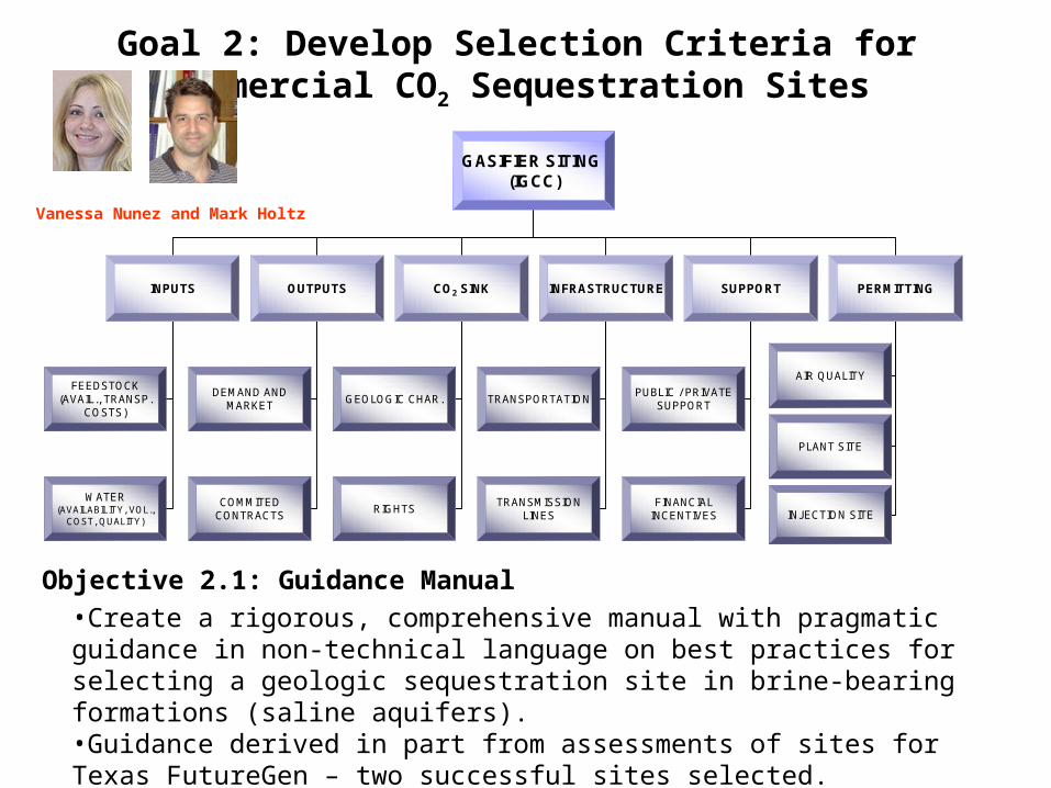
Goal 2: Develop Selection Criteria for Commercial CO2 Sequestration Sites
Goal 2: Develop Selection Criteria for Commercial CO2 Sequestration Sites
GASIFIER SITING (IGCC)
INPUTS OUTPUTS CO2 SINK INFRASTRUCTURE SUPPORT PERMITTING
FEEDSTOCK(AVAIL., TRANSP.
COSTS)TRANSPORTATION
DEMAND AND MARKET
GEOLOGIC CHAR.PUBLIC / PRIVATE
SUPPORT
AIR QUALITY
COMMITED CONTRACTS
WATER (AVAILABILITY, VOL.,
COST, QUALITY)
FINANCIAL INCENTIVES
TRANSMISSION LINES
PLANT SITE
INJECTION SITERIGHTS
•Create a rigorous, comprehensive manual with pragmatic guidance in non-technical language on best practices for selecting a geologic sequestration site in brine-bearing formations (saline aquifers). •Guidance derived in part from assessments of sites for Texas FutureGen – two successful sites selected.
Objective 2.1: Guidance Manual
Vanessa Nunez and Mark Holtz
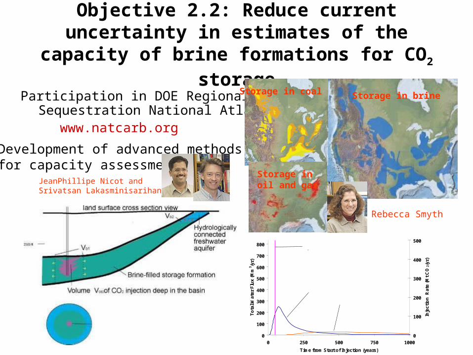
Objective 2.2: Reduce current uncertainty in estimates of the capacity of brine formations
for CO2 storage
Participation in DOE Regional Carbon Sequestration National Atlas
www.natcarb.org
Development of advanced methodsfor capacity assessment
0
100
200
300
400
500
600
700
800
0 250 500 750 1000
Time from Start of Injection (years)
To
tal W
ate
r F
lux
(M
m3 /y
r)
0
100
200
300
400
500
Inje
cti
on
Ra
te (
Mt
CO
2/y
r)
Injection rate
Total water flux at 30 km
Total water flux at 100 km
Storage in brine Storage in coal
Storage in oil and gasJeanPhillipe Nicot and
Srivatsan Lakasminisarihan
Rebecca Smyth

Options for Estimating Capacity
• Volumetric approach: Total pore volume x Efficiency factor (E)– Free CO2 volume in structural and stratigraphic traps– Trapped CO2 residual phase
• Volume dissolved• Volume that can be stored beneath an area
constrained by surface uses or by other unacceptable risks – well fields, faults
• Maximum pressure as a limit on capacity• Displaced water as a limit on capacity
Vol
umet
ricR
isk-
base
d
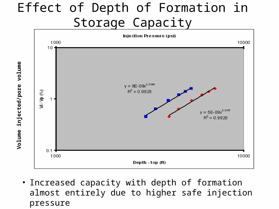
Effect of Depth of Formation in Storage Capacity
• Increased capacity with depth of formation almost entirely due to higher safe injection pressure
Vo
lum
e in
ject
ed/p
ore
vo
lum
e

Goal 3: Define an Adequate and Reliable Monitoring and Verification Strategy
Applicable to Long Term Storage
• Objective 3.1: Evaluate existing approaches for monitoring and verification of CO2 storage in brine formations by assessing sensitivity, accuracy and precision of tools relative to plausible leakage signals.
• Objective 3.2: To Develop and evaluate innovative technologies for “Early Warning” detection of CO2 leakage
• Objective 3.3: Test an innovative approach to monitoring and verification of CO2 storage by combining measurements of deformation with
geomechanical modeling.

Goal 3: Field Tests of Monitoring and Verification Technologies
Goal 3: Field Tests of Monitoring and Verification Technologies
Field project #2in process Cranfield
Proposed East TexasFutureGen Site
Proposed West TexasFutureGen Site
Frio Test Site
SACROC

Injection well
Observation well
Injection Well Observation Well
30 m
U-tubes
RST logs
Frio “Blue”
Sandstone
15m thick
Tubing hung seismic source
and hydrophones
Downhole P and T
Frio Brine Pilot near Houston TX

Early Warning Monitoring Options
• Atmosphere– Ultimate receptor but dynamic
• Biosphere– Assurance of no damage but
dynamic• Soil and Vadose Zone
– Integrator but dynamic• Aquifer and USDW
– Integrator, slightly isolated from ecological effects
• Above injection monitoring zone– First indicator, monitor small signals,
stable. • In injection zone - plume
– Oil-field type technologies. Will not identify small leaks
• In injection zone - outside plume– Assure lateral migration of CO2 and
brine is acceptable
Aquifer and USDW
Atmosphere
Biosphere
Vadose zone & soil
Seal
Seal
CO2 plume
Monitoring Zone

In-house software development for fault/fracturestability analysesAssessing Pressure and Tilt
tip
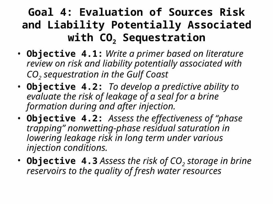
Goal 4: Evaluation of Sources Risk and Liability Potentially Associated with CO2
Sequestration• Objective 4.1: Write a primer based on literature review
on risk and liability potentially associated with CO2 sequestration in the Gulf Coast
• Objective 4.2: To develop a predictive ability to evaluate the risk of leakage of a seal for a brine formation during and after injection.
• Objective 4.2: Assess the effectiveness of “phase trapping” nonwetting-phase residual saturation in lowering leakage risk in long term under various injection conditions.
• Objective 4.3 Assess the risk of CO2 storage in brine reservoirs to the quality of fresh water resources

Non-wetting Residual Phase Trapping Mechanism
CaptureLand surface
> 800 m
Injection Zone
Seal = capillary or pressure barrier to flow
CO2

Risk to Underground Sources of Drinking Water
Capture Land surface
> 800 m
Underground Sources of Drinking Water
Injection Zone
CO2
HypothesizedBrine leak path
HypothesizedCO2 leak path

Preliminary Analysis of Risk to Drinking Water from CO2 leakage
U
-20
-10
0
10
20
30
0 2 4 6 8
Sample
1
2
3
4
5
6
7
8
9
10
11
Corrine Wong

Goal 5: Evaluation of Economic Potential of CO2 to Enhance Oil and Gas Recovery in the Gulf
Coast
• Objective 5.1: To create more accurate predictions of oil-production and CO2 usage for CO2 EOR floods in Gulf Coast clastic reservoirs
• Objective 5.2: Quantify the sequestration potential and feasibility of enhanced gas recovery potential for depleted gas reservoirs in Texas.

Simplified Model Using Dimensionless Groups for Rapid Assessment of CO2 Flooding and Storage in Gulf Coast
Reservoirs
• Model can be applied to candidate Gulf Coast reservoirs in BEG database – limited data on many reservoirs
• Potential for use by small and big operators alike to quickly identify best reservoirs
CO2 Injection and Production
0.00E+00
1.00E+09
2.00E+09
3.00E+09
4.00E+09
0 25 50 75 100 125
Time (days)
Volu
me
(SCF
)
Injected
Produced
Derek Wood, Larry Lake
Derek Woods Larry lake

Improving Economic Assessment (EOR)
Mark Holtz and others

QAc4748x
Cumulative production > 1 MMSTB
No
Rejected
Yes
No
Minimum miscibility
Pressure (depth, temperature, pressure, oil
character) Unknown
Rejected
Oil-reservoir data base
Reservoir depth
>6000 ftYes
Yes
No
Rejected
No
Rejected
Does reservoir have water-
drive mechanism?
Yes
Candidate reservoir
No
Has reservoir been
waterflooded?
Candidate for
secondary
recovery
Yes
BureauofEconomic
Geology
Bureau of Economic Geology
Decision Tree for Screening Candidate Reservoirs

Recovery Efficiency of Sandstone Reservoirs from Enhanced Oil Recovery Projects (1980’s)
Fre
qu
enc
y
Recovery efficiency (percent)
Submarine fan
Barrier/strandplain
Fluvial/deltaic
QAc4237c
0
2
3
4
0 6 12 18 24 30 36 42
1
5
6
7
17%, Little Creek, MS, Denbury (2004)
14.5 %, Paradis, LA, Texaco
Quarantine Bay, LA, Chevron
Single well huff ’n’ puff
Bureau of Economic Geology

CO2 sequestration capacity in miscible oil reservoirs along the Gulf Coast
Bureau of Economic Geology

Goal 6: Development of Market Framework and Economic Models for CO2 Capture and Storage
in the Gulf Coast
• Objective 6.1: Provide to the GCCC partners scenarios and analysis of the policy options under consideration at the State and Federal levels.
• Objective 6.2: To model possible evolutionary pathways for CO2 pipeline networks in the Gulf Coast and their impact on CO2 value chains

Model possible evolutionary pathways for CO2 pipeline networks in the Gulf Coast and their
impact on CO2 Value Chains
Assessment byJoseph Essandoh-YedduEnergy Commission, Ghana

Goal 7: GCCC Service and Training to Partners
• Training tailored to sponsor requests
• Public materials
• Specific data sets developed for sponsors
Workshop for operators

Gulf Coast Carbon Center
Gulf Coast Carbon Center
www.gulfcoastcarbon.org