Embed Size (px)
Citation preview
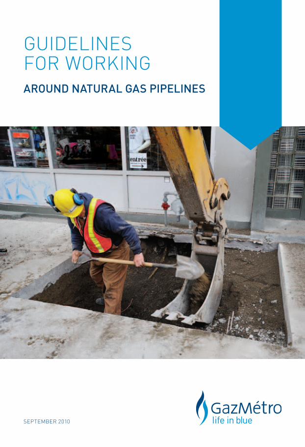
september 2010
GUIDelInes FOr WOrKInGaround natural gas pipelines
2
gaz Métro
With assets of almost $3.6 million and more than 1,300 employees in Québec, Gaz Métro is a major Québec energy company and one of the largest natural gas distributors in Canada. Gaz Métro serves about 180,000 cus-tomers in 12 regions of Québec through an underground gas network spanning over 10,000 km, including high pressure gas lines (equipped with servitudes) totaling nearly 1,000 km and requiring specific procedures (see Section 3 of this Guide).
Pipelines safety and supply reliability are primary concerns, and Gaz Métro endeavours to ensure that all involved are aware of the existence of natural gas installations and of the specific measures to be taken in their presence.
Foreword
This Guide is intended for anyone involved in planning or carrying out work around natural gas pipelines or any other component of the Gaz Métro natural gas network. It indicates the directives to be followed and specifies the general technical requirements aimed at protecting natural gas installations, and by extension, securing public and worker safety.
The Guide contains essential information the individuals planning and performing the work will need to draft their operations, scheduling and costs as per Gaz Métro’s requirements. Nevertheless, designing the work and choosing the appropriate methods and work practices in compliance with these requirements shall be the sole responsibility of those performing the work. Methods requiring Gaz Métro’s specific approval are addressed later in this Guide.
The terms “gas lines”, “gas pipelines” and “gas network” used throughout this Guide apply equally to natural gas mains and service lines, as well as any other component of Gaz Métro natural gas installations system found on public or private land.
It is understood that all legal provisions applicable to work carried out around natural gas pipelines, especially those in Chapter II (Gas) of the Construction Code (L.R.Q. c. B-1.1, r.0.01.01) and the Safety Code related to the construction industry (L.R.Q. c. S-2.1, r. 6), take precedence over this Guide.
about this publication
This is the 5th edition of the Guide and it replaces the earlier edition published in January 2004. The Guide is published in French and in English. You can always consult the most recent version of the Guide on Gaz Métro’s website at: www.gazmetro.com/securite.
Printed copies of the Guide are also available from Gaz Métro.
Please address requests to the Public Relations Department:
1717, rue du Havre Montréal (Québec) H2K 2X3 Tel.: 514 598-3449
3
table oF contents
In case of an eMergency . . . . . . . . . . . . . . . . . . . . . . . . . . . . . . . . . . . . . . . . . . . . . . . . . . . . . . . . . 4
PLannIng yoUr ProJecT . . . . . . . . . . . . . . . . . . . . . . . . . . . . . . . . . . . . . . . . . . . . . . . . . . . . . . . . . . . 5
1. Requesting plans . . . . . . . . . . . . . . . . . . . . . . . . . . . . . . . . . . . . . . . . . . . . . . . . . . . . . . . . . . 5
2. Depth of gas installations . . . . . . . . . . . . . . . . . . . . . . . . . . . . . . . . . . . . . . . . . . . . . . . . . 5
3. High-pressure gas pipelines (equipped with servitudes) . . . . . . . . . . . . . . 6
4. Consequences of your project on the natural gas network . . . . . . . . . . . . 6
eXecUTIng yoUr ProJecT . . . . . . . . . . . . . . . . . . . . . . . . . . . . . . . . . . . . . . . . . . . . . . . . . . . . . . . . . . 7
a. Locating gas lines . . . . . . . . . . . . . . . . . . . . . . . . . . . . . . . . . . . . . . . . . . . . . . . . . . . . . . . . . . 7
B. General safety measures according to type of work . . . . . . . . . . . . . . . . . . . . 7
c. Digging trenches . . . . . . . . . . . . . . . . . . . . . . . . . . . . . . . . . . . . . . . . . . . . . . . . . . . . . . . . . . . 9
D. Clearance . . . . . . . . . . . . . . . . . . . . . . . . . . . . . . . . . . . . . . . . . . . . . . . . . . . . . . . . . . . . . . . . . . . 11
e. Installation by drilling. . . . . . . . . . . . . . . . . . . . . . . . . . . . . . . . . . . . . . . . . . . . . . . . . . . . . .. 13
f. Underground structures . . . . . . . . . . . . . . . . . . . . . . . . . . . . . . . . . . . . . . . . . . . . . . . . . . . 14
g. Backfilling and covering . . . . . . . . . . . . . . . . . . . . . . . . . . . . . . . . . . . . . . . . . . . . . . . . . . . 15
H. Blasting . . . . . . . . . . . . . . . . . . . . . . . . . . . . . . . . . . . . . . . . . . . . . . . . . . . . . . . . . . . . . . . . . . . . . 16
aPPenDIX 1 Natural gas pipelines characteristics . . . . . . . . . . . . . . . . . . . . . . . . . . . . . . . . . 17
aPPenDIX 2 Crossing underground structures . . . . . . . . . . . . . . . . . . . . . . . . . . . . . . . . . . . . 18
aPPenDIX 3 Crossing metallic structures . . . . . . . . . . . . . . . . . . . . . . . . . . . . . . . . . . . . . . . . . . 19
aPPenDIX 4 Backfilling . . . . . . . . . . . . . . . . . . . . . . . . . . . . . . . . . . . . . . . . . . . . . . . . . . . . . . . . . . . . . . 20
aPPenDIX 5 Final covering . . . . . . . . . . . . . . . . . . . . . . . . . . . . . . . . . . . . . . . . . . . . . . . . . . . . . . . . . . 21
aPPenDIX 6 Hydro-excavation . . . . . . . . . . . . . . . . . . . . . . . . . . . . . . . . . . . . . . . . . . . . . . . . . . . . . . 22
aPPenDIX 7 Blasting . . . . . . . . . . . . . . . . . . . . . . . . . . . . . . . . . . . . . . . . . . . . . . . . . . . . . . . . . . . . . . . . . 23
aPPenDIX 8 Specific expertise . . . . . . . . . . . . . . . . . . . . . . . . . . . . . . . . . . . . . . . . . . . . . . . . . . . . . . 26
4
in case oF an eMergency
Accidents cAn occur even if All the AppropriAte meAsures hAve been Applied.
In the event of a break in a natural gas pipeline or any other component of the natural gas network:
1. Cease working.
Let the natural gas escape into the air and do not attempt to backfill or seal off the leak.
2. Avoid flames and sparks.
Shut off the engines of heavy machinery and of all other motorized or electrical equipment. Eliminate all sources of ignition or sparks, including the use of switches, portable telephones and any other piece of non-explosion proof equipment.
3. Do not smoke.
4. Move away from the source of the leak.
5. Immediately call 911.
6. Should the natural gas ignite, do not attempt to put out the flames unless lives are in danger.
Gaz Métro must also be advised of any damage to its natural gas infrastructure, i.e. pipelines, coating, tracer wires, warning tapes, anodes, meters, regulators, etc., even if the damage has not caused a gas leak. To notify Gaz Métro, call 514 598-3111 in the Montréal area or 1 800 361-8003 elsewhere in Québec.
5
planning your project
1. Requesting plans
When planning your project, it is important to factor in the presence of the natural gas network around your worksite in order to:
> avoid any last-minute changes before or during the work;
> plan all the safety measures needed and evaluate the associated costs;
> warn those involved in order to minimize the risk of incidents.
You need to request plans from Info-Excavation for information on Gaz Métro’s network. Allow approximately one (1) week to obtain the plans.
Montréal area 514 286-9228
Elsewhere in Québec 1 800 663-9228
www.info-ex.com
Only the natural gas mains in operation are indicated on the plans. Service lines and other components do not appear, with some exceptions.
Obtaining this information in no way exempts you from the obligation, once onsite, of making a second request to Info-Excavation for the location of all underground natural gas infrastructures before beginning.
2. Depth of gas installations
The depth of natural gas installations and other underground gas infrastructures varies according to location and has to be determined by means of test cuts.
Depending on the nature of the work planned, it may be necessary to ascertain the depth of the gas installations at the project planning stage in order to avoid any setbacks. If test cuts have to be performed by Gaz Métro, please contact our Service Centre at 514 598-3880 or 1 888 598-3880. Test cuts are at the applicant’s expense.
6
3. high-pRessuRe gas pipelines (equippeD with seRvituDes)
Before planning a project (excavation, heavy traffic, etc.) around transmission gas lines (whether servitude or public rights-of-way zones), you must first request a written authorization from Gaz Métro by phoning, faxing or emailing the numbers or addresses appearing below.
Allow 20 business days from the date you submit your request to receive your authorization. Be sure to factor in this lead time when making your request to avoid setbacks, last-minute changes and prevent accidents.
Montréal area: 514 598-3450
Toll-free: 1 866 630-3450
Fax: 514 598-3083
Email: [email protected]
4. ConsequenCes of youR pRojeCt on the natuRal gas netwoRk
It is important that you communicate with Gaz Métro in the early stages of planning a project that includes, for example, modifying the use or profile of the land, or installing or moving underground infrastructures.
The nature and scope of the work planned may call for putting specific safety measures in place, and in certain cases moving or replacing natural gas installations altogether.
Such circumstances will require Gaz Métro to conduct a study with you on the project’s impact on natural gas installations in order to determine possible options, evaluate the cost of performing the work, and estimate an appropriate timeframe.
For all requests of this nature, communicate with our Service Centre at 514 598-3880 in the Montréal area or at 1 888 598-3880 elsewhere in Québec. The cost of the study shall be incurred by the applicant.

7
executing your project
appRoveD woRk methoDs
The work methods below constitute methods approved by Gaz Métro designed to prevent its natural gas infrastructures from being damaged. Companies and indi- viduals complying with these methods are not required to obtain specific approval from Gaz Métro to carry out the work as outlined in Paragraph 2 of Section 3.15.1 of the Safety Code related to the construction industry (L.R.Q., c. S-2.1, r.6).
a – loCating gas lines
Do you have your valid locate ticket in your possession? If not, do not begin any of the operations described in this section.
Before beginning any kind of work – e.g. digging, drilling, sawing or breaking up asphalt, vacuum excavation, scarification(1) – regardless of depth, you must:
> Have had any natural gas pipelines (and other underground gas infrastructures) located;
> Have your valid locate ticket in your possession.
To request a locate ticket, contact Info-Excavation:
Montréal area 514 286-9228
Elsewhere in Québec 1 800 663-9228
www.info-ex.com
Allow 3 complete business days from the date of your request to obtain the information and the locate ticket. Be sure to factor in this lead time when making your request to avoid setbacks, last-minute changes and prevent accidents.
B – geneRal safety measuRes aCCoRDing to type of woRk
B.1 Prevention
The contractor must ensure that everyone on the worksite is aware of the presence of natural gas installations and that they have the locate documents issued by Gaz Métro in their possession at all times.
Note (1): Scarification beyond the asphalt’s thickness.
8
The visual location markers put in place by Gaz Métro technicians must be protected by the worksite manager, especially when there is a risk they may disappear during the course of the work (e.g. when the paving surface is being removed).
When excavation work (including drilling, installing stakes for sidewalks, piles, posts, etc.) is carried out less than three (3) metres from a gas pipeline identified as a high-pressure natural gas pipeline on the locate ticket (1000 kPa and up), a Gaz Métro technician must be onsite. This information will appear on the locate ticket. Be sure to read it thoroughly before initiating any excavation work. Gaz Métro may also decide, at its own discretion, that a technician needs to be present under other circumstances as well.
B.2 Protecting natural gas installations
It is important at all times to protect any natural gas installations uncovered dur- ing work from all types of mistreatment potentially deriving from e.g. construction equipment, vandalism, traffic accidents, exposure to the sun, etc. Gas pipelines, their coating and related components must be protected.
Recognized measures such as the use of concrete barrier curbs (New Jersey), guard rails, plywood, encasements, tarps(1), etc. must be put in place, depending on the circumstances proper to the worksite.
Gas pipelines and related components must not be used as steps, support or anchor points.
Care must also be exercised to avoid damaging the anode connections on the cathode protection on steel pipelines. The same care must be reserved for the tracer wire installed on all natural gas mains and polyethylene service lines, as well as certain steel service lines. As the backfilling work progresses, the anodes, tracer wire and any other equipment belonging to Gaz Métro must be reinstalled, when necessary.
Gaz Métro must be advised of any damage to its natural gas infrastructures (e.g. pipelines, coating, tracer wires, warning tapes, anodes or any other components linked to the Gaz Métro network). Only Gaz Métro employees are qualified to check the condition of damaged natural gas infrastructures and make the necessary repairs.
Note (1): Used to protect the polyethylene and coating against heat.
9
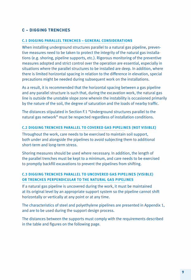
C – Digging tRenChes
c.1 Digging Parallel trenches – general consiDerations
When installing underground structures parallel to a natural gas pipeline, preven- tive measures need to be taken to protect the integrity of the natural gas installa- tions (e.g. shoring, pipeline supports, etc.). Rigorous monitoring of the preventive measures adopted and strict control over the operation are essential, especially in situations where the parallel structures to be installed are deep. In addition, where there is limited horizontal spacing in relation to the difference in elevation, special precautions might be needed during subsequent work on the installations.
As a result, it is recommended that the horizontal spacing between a gas pipeline and any parallel structure is such that, during the excavation work, the natural gas line is outside the unstable slope zone wherein the instability is occasioned primarily by the nature of the soil, the degree of saturation and the loads of nearby traffic.
The distances stipulated in Section F.1 “Underground structures parallel to the natural gas network” must be respected regardless of installation conditions.
c.2 Digging trenches Parallel to covereD gas PiPelines (not visiBle)
Throughout the work, care needs to be exercised to maintain soil support, both under and alongside the pipelines to avoid subjecting them to additional short-term and long-term stress.
Shoring measures should be used where necessary. In addition, the length of the parallel trenches must be kept to a minimum, and care needs to be exercised to promptly backfill excavations to prevent the pipelines from shifting.
c.3 Digging trenches Parallel to uncovereD gas PiPelines (visiBle)
or trenches PerPenDicular to the natural gas PiPelines
If a natural gas pipeline is uncovered during the work, it must be maintained at its original level by an appropriate support system so the pipeline cannot shift horizontally or vertically at any point or at any time.
The characteristics of steel and polyethylene pipelines are presented in Appendix 1, and are to be used during the support design process.
The distances between the supports must comply with the requirements described in the table and figures on the following page.
10
Gaspipeline
FIGURE 1
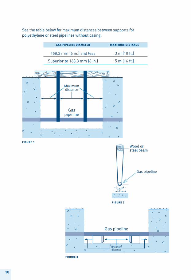
gaspipelinediameter maximumdistance
168.3 mm (6 in.) and less 3 m (10 ft.)
superior to 168.3 mm (6 in.) 5 m (16 ft.)
FIGURE 3
Gas pipeline
See the table below for maximum distances between supports for polyethylene or steel pipelines without casing:
Gas pipeline
Wood orsteel beam
FIGURE 2
11
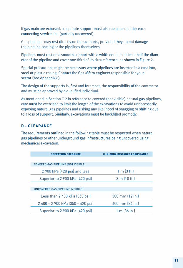
Operatingpressure minimumdistancecOmpliance
covered gas pipeline (not visible)
2 900 kpa (420 psi) and less 1 m (3 ft.)
superior to 2 900 kpa (420 psi) 3 m (10 ft.)
uncovered gas pipeline (visible)
less than 2 400 kpa (350 psi) 300 mm (12 in.)
2 400 – 2 900 kpa (350 – 420 psi) 600 mm (24 in.)
superior to 2 900 kpa (420 psi) 1 m (36 in.)
If gas main are exposed, a separate support must also be placed under each connecting service line (partially uncovered).
Gas pipelines may rest directly on the supports, provided they do not damage the pipeline coating or the pipelines themselves.
Pipelines must rest on a smooth support with a width equal to at least half the diam-eter of the pipeline and cover one third of its circumference, as shown in Figure 2.
Special precautions might be necessary where pipelines are inserted in a cast iron, steel or plastic casing. Contact the Gaz Métro engineer responsible for your sector (see Appendix 8).
The design of the supports is, first and foremost, the responsibility of the contractor and must be approved by a qualified individual.
As mentioned in Section C.2 in reference to covered (not visible) natural gas pipelines, care must be exercised to limit the length of the excavations to avoid unnecessarily exposing natural gas pipelines and risking any likelihood of snagging or shifting due to a loss of support. Similarly, excavations must be backfilled promptly.
D - CleaRanCe
The requirements outlined in the following table must be respected when natural gas pipelines or other underground gas infrastructures being uncovered using mechanical excavation.
12
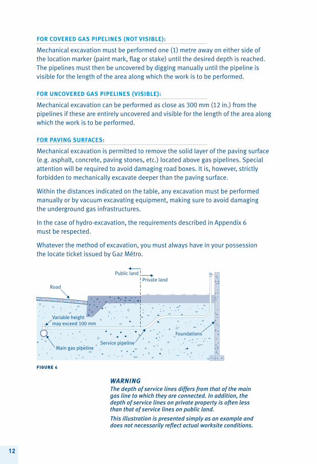
Main gas pipelineService pipeline
FIGURE 4
WARNINGThe depth of service lines differs from that of the main gas line to which they are connected. In addition, the depth of service lines on private property is often less than that of service lines on public land.
This illustration is presented simply as an example and does not necessarily reflect actual worksite conditions.
For covereD gas PiPelines (not visiBle):
Mechanical excavation must be performed one (1) metre away on either side of the location marker (paint mark, flag or stake) until the desired depth is reached. The pipelines must then be uncovered by digging manually until the pipeline is visible for the length of the area along which the work is to be performed.
For uncovereD gas PiPelines (visiBle):
Mechanical excavation can be performed as close as 300 mm (12 in.) from the pipelines if these are entirely uncovered and visible for the length of the area along which the work is to be performed.
For Paving surFaces:
Mechanical excavation is permitted to remove the solid layer of the paving surface (e.g. asphalt, concrete, paving stones, etc.) located above gas pipelines. Special attention will be required to avoid damaging road boxes. It is, however, strictly forbidden to mechanically excavate deeper than the paving surface.
Within the distances indicated on the table, any excavation must be performed manually or by vacuum excavating equipment, making sure to avoid damaging the underground gas infrastructures.
In the case of hydro-excavation, the requirements described in Appendix 6 must be respected.
Whatever the method of excavation, you must always have in your possession the locate ticket issued by Gaz Métro.
13
Drilling across natural gas PiPelines
When the drilling path crosses a natural gas pipeline, the pipeline must first be cleared to the desired depth of the crossing to ensure that the natural gas pipeline is not affected and that the required clearance is respected during all drilling opera- tions (including widening holes and installing the structure, if applicable). Contact the Gaz Métro engineer responsible for your sector (see Appendix 8) to determine the required clearance, which will vary depending on the nature of the work and the type of natural gas installations in place.
e - installation By DRilling
Drilling refers to any method of installation used to install an underground structure without excavating along the total length of the path.
In the case of an installation using directional drilling equipment, the conditions to be respected are set out in the following paragraphs. For installations using any other type of equipment, contact the Gaz Métro engineer responsible for your sector (see Appendix 8).
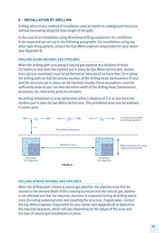
Drilling along natural gas PiPelines
When the drilling path runs along a natural gas pipeline at a distance of three (3) meters or less from the markers put in place by Gaz Métro technicians, excava-tions (access manholes) must be performed at intervals of no more than 10 m along the drilling path so that the precise location of the drilling head, backreamers (if any) and the structure put in place can be checked visually. These excavations must be sufficiently wide so you can view the entire width of the drilling head, backreamers, structures, etc. from entry point to exit point.
No drilling installation is to be performed within a distance of 1 m or less from the markers put in place by Gaz Métro technicians. This prohibited zone may be widened in some cases.
Excavationfor inspection
Excavationfor inspection
Maximum 10 m
Prohibited drilling zone
Width necessary for visual inspection of the drill
Localized and marked natural gas pipeline
1 m
FIGURE 5
14
The excavation must be wide enough on either side of the pipeline to interrupt the drilling operation if an anomaly is detected and before there is any contact with the pipeline.
Refer to sections D “Clearance” and C.3 “Digging trenches parallel to uncovered gas pipelines (visible) or trenches perpendicular to natural gas pipelines” for the appropriate procedures for uncovering a pipeline and installing the necessary supports, if applicable.
f – unDeRgRounD stRuCtuRes
F.1 unDergrounD structures Parallel to natural gas PiPelines
Underground structures parallel to natural gas pipelines, e.g. sewer lines, water mains, cables, pillars or any other type of underground structure, must be located at least 1 m (3 ft.) from Gaz Métro installations to facilitate any future work.
When this distance cannot be respected, special measures need to be considered. In such situations, contact the Gaz Métro engineer responsible for your sector (see Appendix 8) to propose an alternative solution for approval.
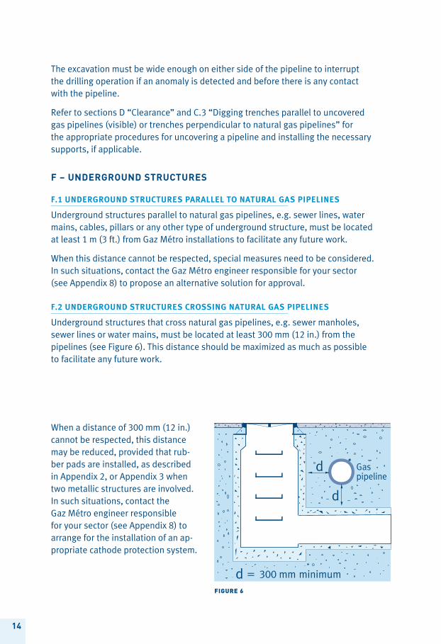
F.2 unDergrounD structures crossing natural gas PiPelines
Underground structures that cross natural gas pipelines, e.g. sewer manholes, sewer lines or water mains, must be located at least 300 mm (12 in.) from the pipelines (see Figure 6). This distance should be maximized as much as possible to facilitate any future work.
Gaspipeline
FIGURE 6
When a distance of 300 mm (12 in.) cannot be respected, this distance may be reduced, provided that rub-ber pads are installed, as described in Appendix 2, or Appendix 3 when two metallic structures are involved. In such situations, contact the Gaz Métro engineer responsible for your sector (see Appendix 8) to arrange for the installation of an ap-propriate cathode protection system.
15
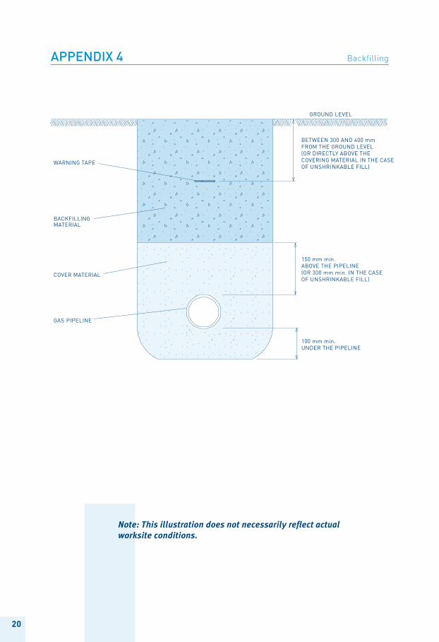
(*) When using unshrinkable backfill, increase the backfill thickness to 300 mm (12 in) above the pipelines.
g – BaCkfilling anD CoveRing
g.1 BackFilling
To avoid damaging the coating on the gas pipelines, backfill material must consist of well graduated natural sand (grading range: 100% passing a 5 mm sieve, 0-10% passing a 0.08 mm sieve). Crushed gravel (grading range: 100% passing a 5 mm sieve and 0-10% passing a 0.08 mm sieve), or 5-0 mm crushed stone with a maximum of 14% passing a 0.08 mm sieve are also acceptable materials.
Backfilling of natural gas pipelines must be performed as follows:
> 100 mm (4 in.) below the gas pipelines;
> 150 mm (6 in.) alongside the gas pipelines;
> 150 mm (6 in.) above the gas pipelines(*).
A warning tape indicating the presence of a natural gas line must be placed at a distance varying between 300 and 400 mm (12 to 16 in.) on the final surface (see Appendix 4).
Note: Some components of the standard-type cross-section illustrated in the appendix may differ during the excavation, like for example, the absence of a warning tape or the use of different backfill material.
Care must be exercised to ensure that the degree of compaction under the gas pipelines is similar to the requirements stipulated in roadway structural specifi- cations. In the case of installations away from roads, the degree of compaction must be similar to that of the undisturbed surrounding material.
No compaction equipment must be used until the backfill above the gas pipelines reaches a depth of 300 mm (12 in.).
Until the backfill above the gas pipelines reaches 600 mm (24 in.), only light manual compaction equipment must be used (e.g. a vibrating plate, a handheld tamper). Driving over the gas pipeline should be avoided so as to not put excessive stress on it.
In the case of natural gas pipelines operating at more than 2,900 kPa (420 psi), the backfill required for the operations described in the above paragraph have to be individually determined in each case. Contact the Gaz Métro engineer responsible for your sector (see Appendix 8).
16
g.2 Final covering
The final covering of gas pipelines must consistently comply with the minimum requirements described in Appendix 5. They must also adhere to municipal or Transports Québec requirements for lands owned by these or that fall under their jurisdiction, where their requirements are higher than those of Appendix 5.
h – Blasting
Explosives must be used with great care around natural gas pipelines and, unless subject to the exception set out in the last paragraph, in accordance with the standards established by Gaz Métro (see Appendix 7).
A certificate of compliance with the requirements set out in Appendix 7, signed by the contractor responsible for the blasting work, must be given to a Gaz Métro technician upon request. Gaz Métro or its employees may not provide any advice as to the blasting work’s compliance with Appendix 7. It is entirely the responsibility of the contractor to ensure that all blasting work, including that performed by any sub-contractor, respect Appendix 7.
On the Island of Montréal, given the natural gas liquefaction, storage and re-gasification plant located at 11,201 Henri-Bourassa east, the Gaz Métro engineer responsible for your sector (see Appendix 8) must be contacted for any project that requires blasting in the zone east of Marien street and 71st avenue, between Gouin boulevard to the north and Sherbrooke street East to the south.
17
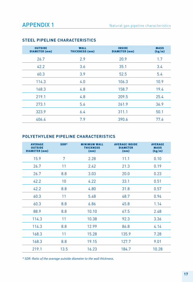
polyethylene pipeline ChaRaCteRistiCs
aVerage sdr* minimumWall aVerageinside aVerage Outside tHicKness diameter mass diameter(mm) (mm) (mm) (kg/m)
15.9 7 2.28 11.1 0.10
26.7 11 2.42 21.3 0.19
26.7 8.8 3.03 20.0 0.23
42.2 10 4.22 33.1 0.51
42.2 8.8 4.80 31.8 0.57
60.3 11 5.48 48.7 0.94
60.3 8.8 6.86 45.8 1.14
88.9 8.8 10.10 67.5 2.48
114.3 11 10.38 92.3 3.36
114.3 8.8 12.99 86.8 4.14
168.3 11 15.28 135.9 7.28
168.3 8.8 19.15 127.7 9.01
219.1 13.5 16.23 184.7 10.28
* SDR: Ratio of the average outside diameter to the wall thickness.
appendix 1 natural gas pipeline characteristics
steel pipeline ChaRaCteRistiCs
Outside Wall inside mass diameter(mm) tHicKness(mm) diameter(mm) (kg/m)
26.7 2.9 20.9 1.7
42.2 3.6 35.1 3.4
60.3 3.9 52.5 5.4
114.3 4.0 106.3 10.9
168.3 4.8 158.7 19.4
219.1 4.8 209.5 25.4
273.1 5.6 261.9 36.9
323.9 6.4 311.1 50.1
406.4 7.9 390.6 77.6
18
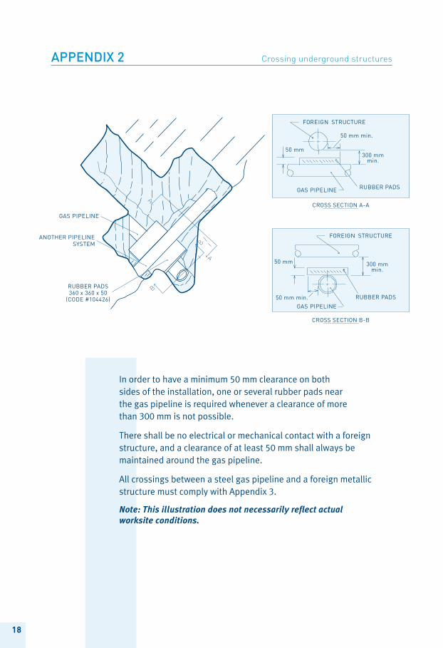
In order to have a minimum 50 mm clearance on both sides of the installation, one or several rubber pads near the gas pipeline is required whenever a clearance of more than 300 mm is not possible.
There shall be no electrical or mechanical contact with a foreign structure, and a clearance of at least 50 mm shall always be maintained around the gas pipeline.
All crossings between a steel gas pipeline and a foreign metallic structure must comply with Appendix 3.
Note: This illustration does not necessarily reflect actual worksite conditions.
appendix 2 Crossing underground structures
19
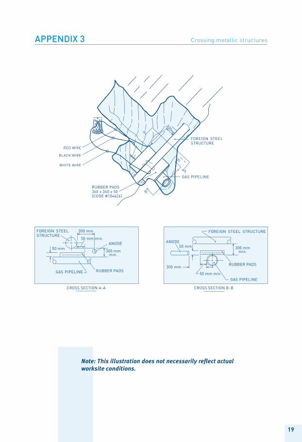
Note: This illustration does not necessarily reflect actual worksite conditions.
appendix 3 Crossing metallic structures
20
Note: This illustration does not necessarily reflect actual worksite conditions.
appendix 4 backfilling
21
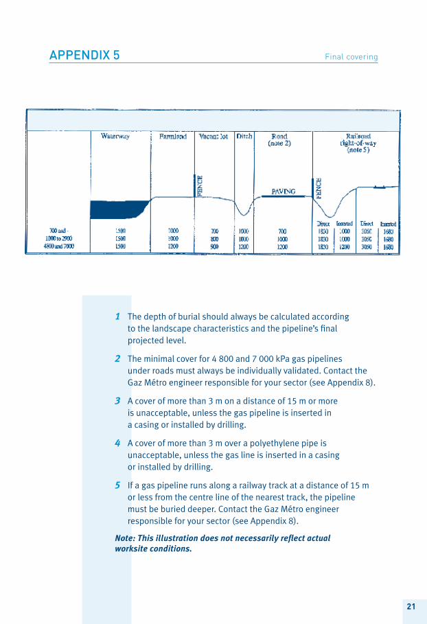
1 The depth of burial should always be calculated according to the landscape characteristics and the pipeline’s final projected level.
2 The minimal cover for 4 800 and 7 000 kPa gas pipelines under roads must always be individually validated. Contact the Gaz Métro engineer responsible for your sector (see Appendix 8).
3 A cover of more than 3 m on a distance of 15 m or more is unacceptable, unless the gas pipeline is inserted in a casing or installed by drilling.
4 A cover of more than 3 m over a polyethylene pipe is unacceptable, unless the gas line is inserted in a casing or installed by drilling.
5 If a gas pipeline runs along a railway track at a distance of 15 m or less from the centre line of the nearest track, the pipeline must be buried deeper. Contact the Gaz Métro engineer responsible for your sector (see Appendix 8).
Note: This illustration does not necessarily reflect actual worksite conditions.
appendix 5 Final covering
22
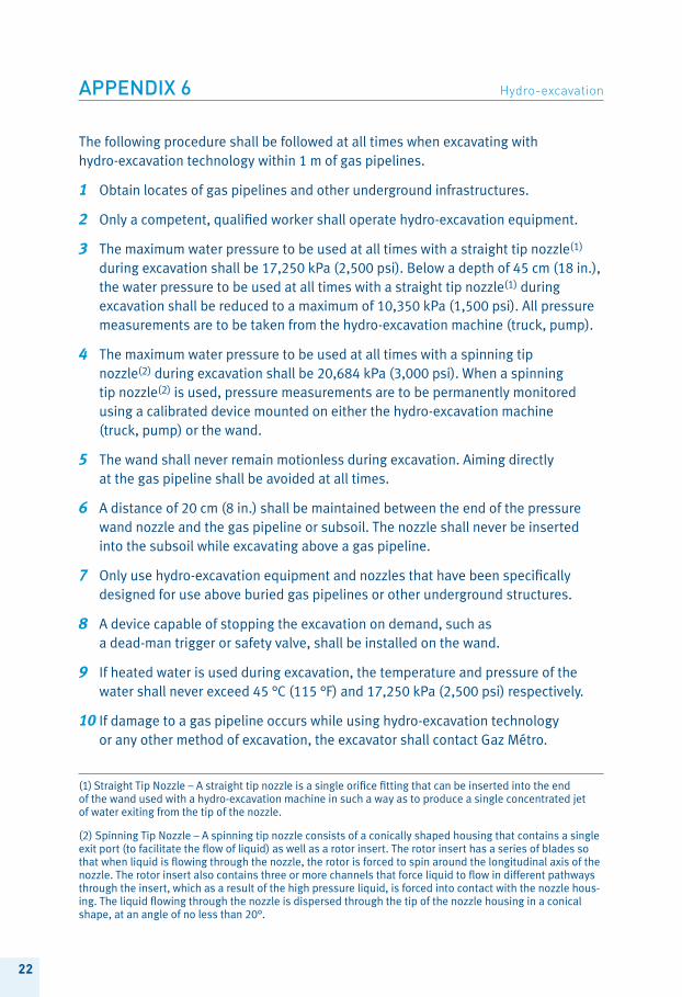
The following procedure shall be followed at all times when excavating with hydro-excavation technology within 1 m of gas pipelines.
1 Obtain locates of gas pipelines and other underground infrastructures.
2 Only a competent, qualified worker shall operate hydro-excavation equipment.
3 The maximum water pressure to be used at all times with a straight tip nozzle(1) during excavation shall be 17,250 kPa (2,500 psi). Below a depth of 45 cm (18 in.), the water pressure to be used at all times with a straight tip nozzle(1) during excavation shall be reduced to a maximum of 10,350 kPa (1,500 psi). All pressure measurements are to be taken from the hydro-excavation machine (truck, pump).
4 The maximum water pressure to be used at all times with a spinning tip nozzle(2) during excavation shall be 20,684 kPa (3,000 psi). When a spinning tip nozzle(2) is used, pressure measurements are to be permanently monitored using a calibrated device mounted on either the hydro-excavation machine (truck, pump) or the wand.
5 The wand shall never remain motionless during excavation. Aiming directly at the gas pipeline shall be avoided at all times.
6 A distance of 20 cm (8 in.) shall be maintained between the end of the pressure wand nozzle and the gas pipeline or subsoil. The nozzle shall never be inserted into the subsoil while excavating above a gas pipeline.
7 Only use hydro-excavation equipment and nozzles that have been specifically designed for use above buried gas pipelines or other underground structures.
8 A device capable of stopping the excavation on demand, such as a dead-man trigger or safety valve, shall be installed on the wand.
9 If heated water is used during excavation, the temperature and pressure of the water shall never exceed 45 °C (115 °F) and 17,250 kPa (2,500 psi) respectively.
10 If damage to a gas pipeline occurs while using hydro-excavation technology or any other method of excavation, the excavator shall contact Gaz Métro.
appendix 6 Hydro-excavation
(1) Straight Tip Nozzle – A straight tip nozzle is a single orifice fitting that can be inserted into the end of the wand used with a hydro-excavation machine in such a way as to produce a single concentrated jet of water exiting from the tip of the nozzle.
(2) Spinning Tip Nozzle – A spinning tip nozzle consists of a conically shaped housing that contains a single exit port (to facilitate the flow of liquid) as well as a rotor insert. The rotor insert has a series of blades so that when liquid is flowing through the nozzle, the rotor is forced to spin around the longitudinal axis of the nozzle. The rotor insert also contains three or more channels that force liquid to flow in different pathways through the insert, which as a result of the high pressure liquid, is forced into contact with the nozzle hous-ing. The liquid flowing through the nozzle is dispersed through the tip of the nozzle housing in a conical shape, at an angle of no less than 20°.
23
Blasting operations around gas pipelines constitute a clear hazard to public safety and the integrity of the Gaz Métro network.
This appendix establishes the procedures to follow for blasting operations around Gaz Métro installations.
> No blasting is permitted at a distance of less than 1.80 m from a 2400 kPa or higher steel pipeline.
> No blasting is permitted at a distance of less than 1.50 m from a <2400 kPa steel pipeline or from a polyethylene pipeline.
pRoCeDuRes to follow
1 Determine the type of explosion:
• Single explosive charge: one simultaneous explosion of every explosive charge.
• Delayed explosions: the explosive charges do not simultaneously go off, but do so at intervals of a few milliseconds. With this type of explosion, it is necessary to ensure an appropriate distance between each explosive charge in order to prevent the first charge from igniting the others.
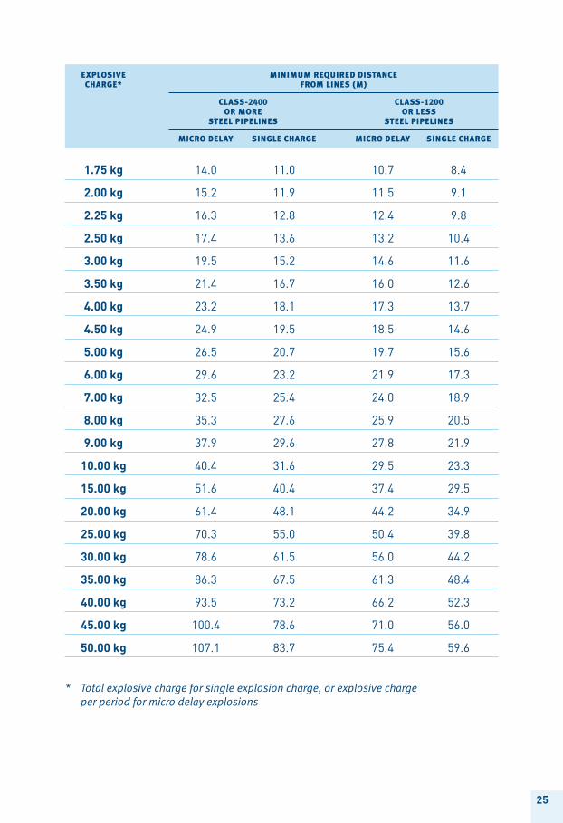
2 Determine the total explosive charge for single explosion charges and the explosive charges per interval for delayed explosions.
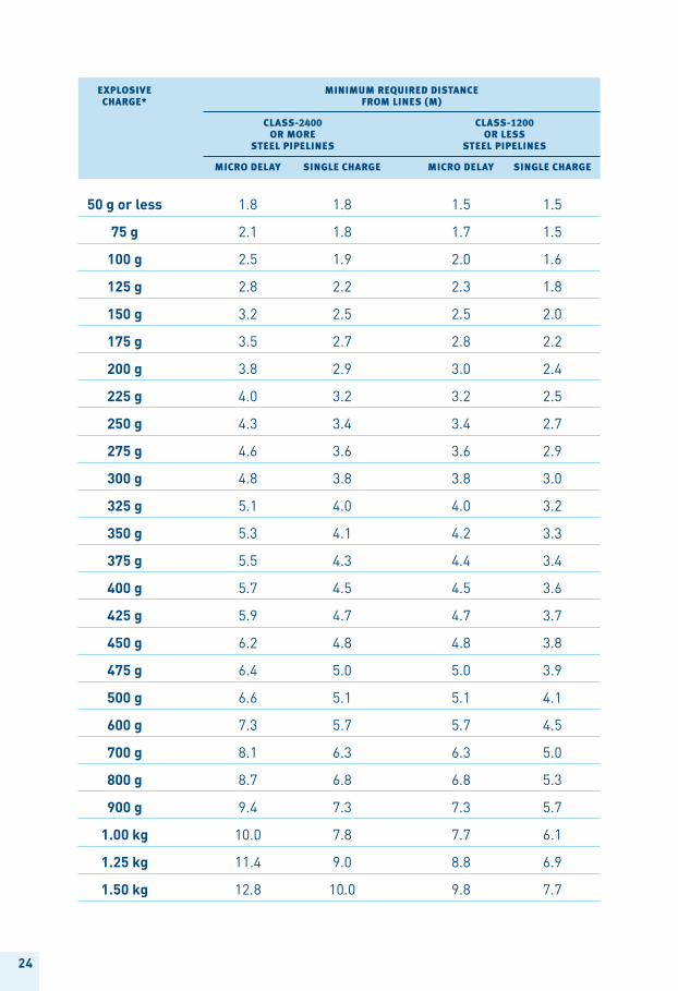
3 Refer to the table on the following page to determine the minimum distance required between charges.
appendix 7 blasting
24
explOsiVe minimumreQuireddistance cHarge* FrOmlines(m)
class-2400 class-1200 OrmOre Orless steelpipelines steelpipelines
micrOdelay singlecHarge micrOdelay singlecHarge
50 g or less 1.8 1.8 1.5 1.5
75 g 2.1 1.8 1.7 1.5
100 g 2.5 1.9 2.0 1.6
125 g 2.8 2.2 2.3 1.8
150 g 3.2 2.5 2.5 2.0
175 g 3.5 2.7 2.8 2.2
200 g 3.8 2.9 3.0 2.4
225 g 4.0 3.2 3.2 2.5
250 g 4.3 3.4 3.4 2.7
275 g 4.6 3.6 3.6 2.9
300 g 4.8 3.8 3.8 3.0
325 g 5.1 4.0 4.0 3.2
350 g 5.3 4.1 4.2 3.3
375 g 5.5 4.3 4.4 3.4
400 g 5.7 4.5 4.5 3.6
425 g 5.9 4.7 4.7 3.7
450 g 6.2 4.8 4.8 3.8
475 g 6.4 5.0 5.0 3.9
500 g 6.6 5.1 5.1 4.1
600 g 7.3 5.7 5.7 4.5
700 g 8.1 6.3 6.3 5.0
800 g 8.7 6.8 6.8 5.3
900 g 9.4 7.3 7.3 5.7
1.00 kg 10.0 7.8 7.7 6.1
1.25 kg 11.4 9.0 8.8 6.9
1.50 kg 12.8 10.0 9.8 7.7
25
explOsiVe minimumreQuireddistance cHarge* FrOmlines(m)
class-2400 class-1200 OrmOre Orless steelpipelines steelpipelines
micrOdelay singlecHarge micrOdelay singlecHarge
1.75 kg 14.0 11.0 10.7 8.4
2.00 kg 15.2 11.9 11.5 9.1
2.25 kg 16.3 12.8 12.4 9.8
2.50 kg 17.4 13.6 13.2 10.4
3.00 kg 19.5 15.2 14.6 11.6
3.50 kg 21.4 16.7 16.0 12.6
4.00 kg 23.2 18.1 17.3 13.7
4.50 kg 24.9 19.5 18.5 14.6
5.00 kg 26.5 20.7 19.7 15.6
6.00 kg 29.6 23.2 21.9 17.3
7.00 kg 32.5 25.4 24.0 18.9
8.00 kg 35.3 27.6 25.9 20.5
9.00 kg 37.9 29.6 27.8 21.9
10.00 kg 40.4 31.6 29.5 23.3
15.00 kg 51.6 40.4 37.4 29.5
20.00 kg 61.4 48.1 44.2 34.9
25.00 kg 70.3 55.0 50.4 39.8
30.00 kg 78.6 61.5 56.0 44.2
35.00 kg 86.3 67.5 61.3 48.4
40.00 kg 93.5 73.2 66.2 52.3
45.00 kg 100.4 78.6 71.0 56.0
50.00 kg 107.1 83.7 75.4 59.6
* Total explosive charge for single explosion charge, or explosive charge per period for micro delay explosions
26
Depending on where your planned project is located, contact the appropriate Gaz Métro engineer at one of the following three (3) telephone numbers:
Sector: Montréal / Laurentides / Montérégie 514 598-3339
Sector: Québec / Saguenay / Mauricie / Estrie 418 577-5555
Sector: Abitibi-Témiscamingue 819 797-2111
appendix 8 specific expertise

27
plAce Your locAte reQuest online www.info-ex.Com montrÉAl 514 286-9228 elsewhere in QuÉbec 1 800 663-9228
contact info-excavation at least three
whole working days before you start to dig.
info-excavation will inform you of the location of
underground networks in the vicinity of your work
site. You can thus proceed in complete safety.
two simple ways to do so:
> by phone: 1 800 663-9228
> online: www.info-ex.com
Free servICe
get t beFor a net For yat least th
get the Facts beFore digging, a net advantage For your saFetyat least three days beFore you start to work

Gaz métrO 1717 DU Havre, mOntréal (qUébeC) H2K 2X3 www.gazMetro.coM
rp
- 5
000
- 1
2/2
010