Embed Size (px)
Citation preview
GUIDELINES FOR THE USE OF WROUGHT WIRE CLASPS FOR
REMOVABLE PARTIAL DENTURES
Lushen Manickum Naidoo
A research report submitted to the School of Oral Health Science, University of the
Witwatersrand, in partial fulfilment for the degree of Master of Dentistry in the branch of
Prosthodontics.
Johannesburg, 2009

DECLARATION
I, Lushen Manickum Naidoo declare that this research report is my own work.
It is being submitted in partial fulfilment of the degree of Master of Dentistry
in the branch of Prosthodontics at the University of the Witwatersrand,
Johannesburg. It has not been submitted before for any degree or examination
at this or any other University.
______________________________ Lushen Manickum Naidoo
___ day of , 2010
ii

DEDICATION
To my family for their unconditional support throughout this journey.
iii
ABSTRACT
Purpose: The purpose of this study was to evaluate the effects of diameter, alloy and clasp
length on the behaviour of different wrought wires in order to produce clinical guidelines
for their selection in removable partial dentures (RPDs).
Method: Three stainless steel round wrought wires were tested: Remanium®; Noninium®
(nickel free) (Dentaurum, Pforzheim, Germany); Leowire® (Leone, Fiorentino, Italy); as
well as two Type IV round wrought gold wires: Degulor® (Degudent, Hanau, Germany)
and Argen (Argen Corp., San Diego, USA). Three diameters (0.8mm, 0.9mm, 1.0mm) of
Remanium and Leowire were used; two diameters (0.8mm, 0.9mm) of Noninium and two
diameters (0.9mm, 1.0mm) of the gold alloy wires were used based on their availability
commercially. Ten samples of each diameter for the different stainless steel wires were
bent to two lengths (12mm and 20mm) to represent the average buccal curvature of
premolars and molars respectively. The gold wires were bent to 12mm, as gold wires are
infrequently used in clinical practice on molar teeth. Each clasp was bent beyond its
proportional limit in a tensile testing machine, and the force exerted was recorded at
deflections which represented the clinically encountered undercuts of 0.25mm, 0.5mm, and
0.75mm.
Results: All the wires in each of the batches behaved consistently. Statistically significant
differences were noted on comparison of the stainless steel wires, the gold wires and gold
versus stainless steel wires. Wide variations in forces exerted by the different clasp
combinations were observed.
Conclusion: The selection of wrought wires for acrylic RPDs is influenced by alloy type
and diameter, length, curvature, and depth of undercut. The data from this study allowed
for the provision of clinical guidelines for the appropriate selection of wrought wire clasps.
iv
ACKNOWLEDGEMENTS
I would like to thank my supervisor, Prof CP Owen for his support, and assistance in the
development of the experiment and in the writing of this report.
Dr Rabia Goolam for use of equipment designed for her study, which employed a method
on which this study was modelled.
Mr Gert Kruger for his assistance during the preparation of the laboratory samples used in
this study.
Mr Iain Ramsey for his assistance with the experimental set-up of the software of the
tensile testing equipment.
Mr Dion van Zyl for his advice, encouragement and the statistical analysis of the results.
Mr Wayne Costopoulos from the Dept of Mechanical Engineering for the construction of
the jigs which fitted onto the tensile testing machine.
v
TABLE OF CONTENTS PAGE
DECLARATION ii
DEDICATION iii
ABSTRACT iv
ACKNOWLEDGEMENTS v
TABLE OF CONTENTS vi
LIST OF FIGURES vii
LIST OF TABLES viii
1. INTRODUCTION AND LITERATURE REVIEW 1
1.1 Introduction 1 1.2 Literature Review 1 1.3 Aim 6
2. MATERIALS AND METHOD 7
2.1 Materials used 7 2.2 Method 8 2.2.1 Determination of sample size 8 2.2.2 Determination of clasp shape 8 2.2.3 Construction of the samples 9 2.2.4 Testing 9
3. RESULTS 13
4. DISCUSSION 18
5. CONCLUSION AND RECOMMENDATIONS 23
5.1 Conclusion 23 5.2 Recommendations 24
6. REFERENCES 25
vi
LIST OF FIGURES
PAGE
Figure 1. Bending of a stainless steel wire 8
Figure 2. 20mm clasp on left and 12mm clasp on right in brass mould 9
Figure 3. Position of clasp and block on jigs of tensile testing machine 10
Figure 4. 12mm clasp on right bent beyond its proportional limit 11
Figure 5: Compensation for slippage of clasp tip 11
vii
viii
LIST OF TABLES
PAGE Table 1. Stainless steel and gold alloys tested 7
Table 2. Calculation of realistic limit (grams force) for each specimen 14
Table 3. Mean loads and realistic limits (in parentheses) for premolar and
molar clasps. Mean loads highlighted in bold (red) represent
values which have exceeded the realistic limit for that deflection 15
Table 4. Selection of clasps for premolars based on maximum loads
achieved by each alloy below the realistic limit 21
Table 5. Selection of clasps for molars based on maximum loads achieved
by each alloy below the realistic limit 21
Table 6. Clasp selection for premolars and molars based on maximum loads
exerted. 22
1. INTRODUCTION AND LITERATURE REVIEW
1.1 Introduction Whilst there are many options available for the replacement of missing teeth, the most
cost-effective is by means of acrylic-based removable partial dentures (RPDs). There is
general consensus in the literature that RPDs will cause biological harm if constructed
inappropriately (Warr 1961; Frank and Nicholls 1981; Owen 2000).
The responsibility for the optimal construction of RPDs should be shared by both the
clinician and the dental technician. However, clinicians should provide the dental
technician with a detailed diagrammatic prescription of the design and components of
RPDs (Owen 2000).
Round wrought wires are commonly used for the fabrication of acrylic RPDs in order to
provide direct retention. Details regarding the optimal prescription of wrought wire clasps
could improve the retentive quality of acrylic RPDs whilst potentially reducing initial
costs.
1.2 Literature Review
Retentive clasp arms exert forces on the teeth they engage, and these forces should not
exceed either the properties of the material, or the ability of the tooth to withstand them
(Frank and Nicholls 1981; Owen 2000).
1
Round wrought wires flex in all directions and have been recommended for use as
retentive clasp arms in all types of RPDs, especially where periodontal support has been
compromised, or the use of a cast clasp has been deemed unsuitable. However, wrought
wires have several potential disadvantages related to failure as a result of poor adaptation,
loss of adaptation after a period of use and susceptibility to fracture (Morris et al. 1983;
Frank and Nicholls 1986; VandenBrink, Wolfaardt and Faulkner 1993).
Contemporary dental literature addresses the behaviour of wrought wire clasps only
superficially. Warr (1959) used mathematical analyses to calculate the influence of alloy
type, diameter, length, taper, cross-sectional shape, and undercut depth on the behaviour of
the retentive arms of clasps. However, the lack of in vitro and in vivo evidence related to
the performance of clasps prior to the 1970s, resulted in the assumption of several
behavioural characteristics related to their performance which have continued to this day.
These assumptions were based mainly on research carried out on cast circumferential
clasps (Warr 1961, Bates 1968).
In vitro studies since the 1970s have shown that the behaviour of round wrought wire
clasps is affected by alloy type, diameter, length, curvature, and deflection (Clayton and
Jaslow 1971; Frank and Nicholls 1981; Morris et al. 1983). However, these observations
were not translated into simple, effective clinical guidelines for the selection of wrought
wire clasps.
A literature search yielded the results of six studies which investigated the behaviour of
round wrought wires. Stobie (1969, cited in Frank and Nicholls 1981) found that the
differences in the curvature of wrought wires of the same diameter resulted in variations in
2
flexibility. Brudvik and Wormley (1973) suggested the selection of a small diameter wire
when clasp length was minimal, but presented no data to justify this. Brudvick and Morris
(1981) studied the influence of the diameter, length and alloy type on the behaviour of
wrought clasps and concluded that the relationship of clasp length to retention and
permanent deformation was fundamental to the performance of these clasps. This would
imply that the in vitro testing of the flexibility of wrought wires should include the
standardisation of active clasp length.
Frank and Nicholls (1981) investigated the effects of diameter, alloy and clasp length on
the flexibility of round wires composed of base-plate and gold alloys. One of the objectives
of that study was to determine the minimum and maximum forces required to maintain the
position of a distal extension RPD. The authors calculated that 300g to 750g (150g to 375g
per clasp) represented an acceptable amount of retention for a bilateral distal extension
base. The presence of passive (guide plane) retention in a tooth-supported base was
thought to require less active retention to keep the RPD in place. These calculations were
compared with load-deflection data of wires of different alloys, diameters and lengths.
Clinical conditions were simulated by soldering the wires onto chromium-cobalt plates
which were then covered by acrylic. Each clasp was bent to its proportional limit in a
tensile testing machine. This study concluded that all the wires tested would provide
sufficient retention when placed in a suitable depth of undercut. However, they did not
specify the ‘suitable’ depth of undercut, and did not standardise the lengths or the
curvature of the wires.
3
In a later publication, Frank (1986) published guidelines for the selection of wrought wire
clasps for RPDs based on periodontal support, reciprocation, clasp length, undercut depth
and retention desired. However, these were based largely on anecdotal evidence.
A MedLine search found studies which provided insight into the relationships of the
factors influencing wrought wire clasp behaviour, but none were able to provide guidelines
related to the selection of these clasps for commonly encountered clinical situations
(Morris et al. 1983; Matheson, Brudvik and Nicholls 1986; VandenBrink et al. 1993;
Shirasu et al. 2008).
A search using the Union Catalogue of Theses and Dissertations yielded one study which
provided such clinical guidelines (Goolam 1992). This was a laboratory-based study which
tested the suitability of stainless steel, chromium-cobalt and gold alloy wrought wire clasps
for the construction of removable partial dentures. Load-deflection data of different
combinations of wires based on diameter, length, alloy type, and depth of undercut were
used in order to produce clinical guidelines for the selection of wire clasps in two
commonly encountered clinical situations, a bounded denture saddle (tooth supported) with
sound or periodontally compromised teeth, and a distal extension base (dento-gingivally
supported) with sound or periodontally compromised teeth. One type of gold alloy
(Platinum-Gold-Palladium; Argon, Johannesburg, South Africa) and one type of stainless
steel wire (Remanium wire, Dentaurum, Pforzheim, Germany) was used.
Waldmeier et al. (1996) studied the differences in flexibility of different gold alloy and
stainless steel wrought wire clasps. These authors found statistically significant differences
in the flexibility of different wires in each of these groups, for a particular undercut. The
4
study concluded that the selection of wrought wire clasps should include differences in
variations of alloy manufacturing and composition. However, only straight wires were
tested, without standardisation of the length of the wires.
A variety of stainless steel and gold alloy wires is currently available for wrought clasps.
These are differentiated based on differences in the manufacturing process, and variations
in alloy composition (Brudvick and Morris 1981). The American Dental Association
classification of dental alloys comprises 3 categories (Craig and Ward 1997):
• High noble (noble metal content > 60% wt and a gold content of > 40% wt)
• Noble (noble metal content > 25% wt, with no stipulation for gold)
• Base metals (noble content < 25% wt)
Many of the base metals are generally referred to as stainless steels (Craig and Ward 1997)
and the most commonly used alloys in clinical practice appear to be gold and stainless steel
(Frank and Nicholls 1981; Brudvick and Morris 1981; Goolam 1992; Waldmeier et al.
1996).
It has been shown that one of the corrosion products of stainless steel wires was nickel
(Shih et al. 2001). In vitro studies have shown that stainless steel corrosion products were
cytotoxic in simulated physiological conditions (Morais et al. 1998; Shih et al. 2001; David
and Lobner 2004). Nickel-induced allergic dermatitis has been reported to be responsible
for more allergic reactions than a combination of all the other commonly used metals in
dentistry (Pourbaix 1984). Up to 21.5 % of the population may show signs of a nickel
related allergic reaction on patch testing (Schubert and Prater 1987 cited in Platt et al.
1997). Therefore the use of nickel-free stainless steel wires has been advocated in
5
orthodontic patients with nickel allergies (Montanaro et al. 2005). Waldmeier et al. (1996)
reported that a decrease in the nickel content of straight stainless steel wires resulted in a
decrease in flexibility, but a MedLine literature search revealed no studies testing these
wires for suitability as clasp arms in RPDs.
No clear guidelines have emerged in the literature. The closest attempt was an unpublished
thesis by Goolam (1992), and as that study used standardised curvatures of round wrought
wires, it was decided to use a similar methodology and to include different types of
stainless steel and gold alloy wrought wires.
1.3 Aim To evaluate the effects of alloy, diameter and clasp length on the behaviour of different
round wrought wire clasps, in order to produce clinical guidelines for the selection of these
clasps for RPDs.
6
2. MATERIALS AND METHOD
2.1 Materials used
Wrought wires are available in round and half round forms. However, round wire is more
easily contoured compared with half-round wire. Therefore only round wrought wires have
been selected for this study. The various types of alloys and their corresponding diameters
were chosen based on commercial availability in South Africa, previous studies (Frank and
Nicholls 1981; Waldmeier et al. 1996) and load-deflection data from Goolam (1992). The
lengths of the wires used were based on premolars and molars, which serve as ideal
abutments for clasping due to their form. It has been shown (Goolam 1992) that the length
of the average curvature of the buccal surface of a premolar is 12 mm and that of a molar,
20 mm. The wires which have been chosen were grouped according to alloy type, diameter
and length (Table 1).
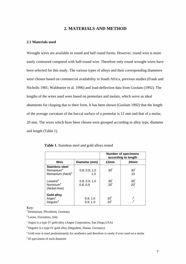
Table 1. Stainless steel and gold alloys tested
Number of specimens according to length
Wire Diameter (mm) 12mm 20mm Stainless steel Remaniuma Remanium (hard)a Leowireb Noniniuma (Nickel-free) Gold alloy Argenc Degulord
0.8; 0.9; 1.0
1.0
0.8; 0.9; 1.0 0.8; 0.9
0.9; 1.0 0.9; 1.0
30f
30f 20f
20f 20f
30f 10
30f 20f
-e -e
Key: a Dentaurum, Pforzheim, Germany b Leone, Fiorentino, Italy c Argen is a type IV gold alloy (Argen Corporation, San Diego,USA) d Degulor is a type IV gold alloy (Degudent, Hanau, Germany) e Gold wire is used predominantly for aesthetics and therefore is rarely if ever used on a molar f 10 specimens of each diameter
7
2.2 Method
2.2.1 Determination of sample size
A statistical calculation of sample size could not be achieved using standard methods, due
to the fact that load-deflection data was being analysed up to the proportional limits of the
wires. A pilot study was not carried out on the basis that none of the previous studies
which were reviewed contained samples in excess of 10 per diameter of wire. It was
expected that the results obtained for each batch of samples in this study would follow a
normal distribution.
2.2.2 Determination of clasp shape
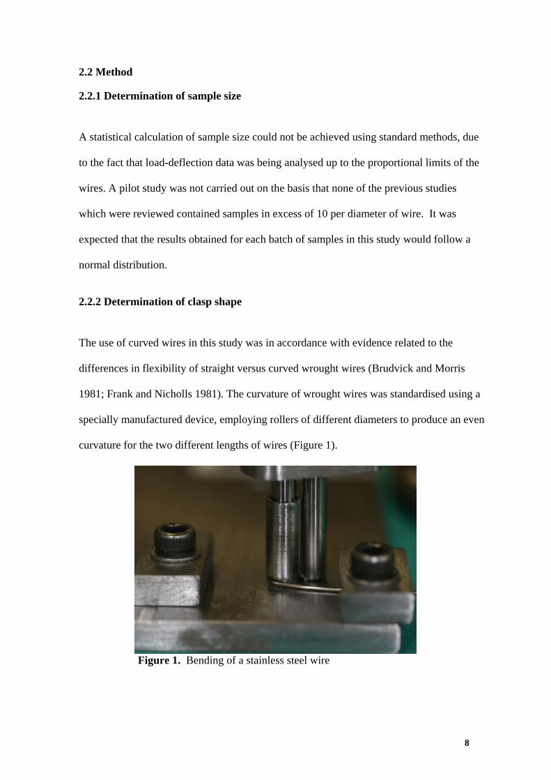
The use of curved wires in this study was in accordance with evidence related to the
differences in flexibility of straight versus curved wrought wires (Brudvick and Morris
1981; Frank and Nicholls 1981). The curvature of wrought wires was standardised using a
specially manufactured device, employing rollers of different diameters to produce an even
curvature for the two different lengths of wires (Figure 1).
Figure 1. Bending of a stainless steel wire
8
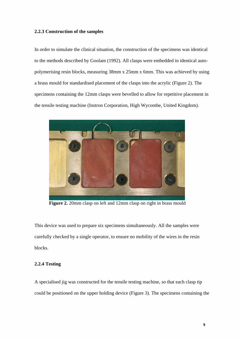
2.2.3 Construction of the samples
In order to simulate the clinical situation, the construction of the specimens was identical
to the methods described by Goolam (1992). All clasps were embedded in identical auto-
polymerising resin blocks, measuring 38mm x 25mm x 6mm. This was achieved by using
a brass mould for standardised placement of the clasps into the acrylic (Figure 2). The
specimens containing the 12mm clasps were bevelled to allow for repetitive placement in
the tensile testing machine (Instron Corporation, High Wycombe, United Kingdom).
Figure 2. 20mm clasp on left and 12mm clasp on right in brass mould
This device was used to prepare six specimens simultaneously. All the samples were
carefully checked by a single operator, to ensure no mobility of the wires in the resin
blocks.
2.2.4 Testing
A specialised jig was constructed for the tensile testing machine, so that each clasp tip
could be positioned on the upper holding device (Figure 3). The specimens containing the
9
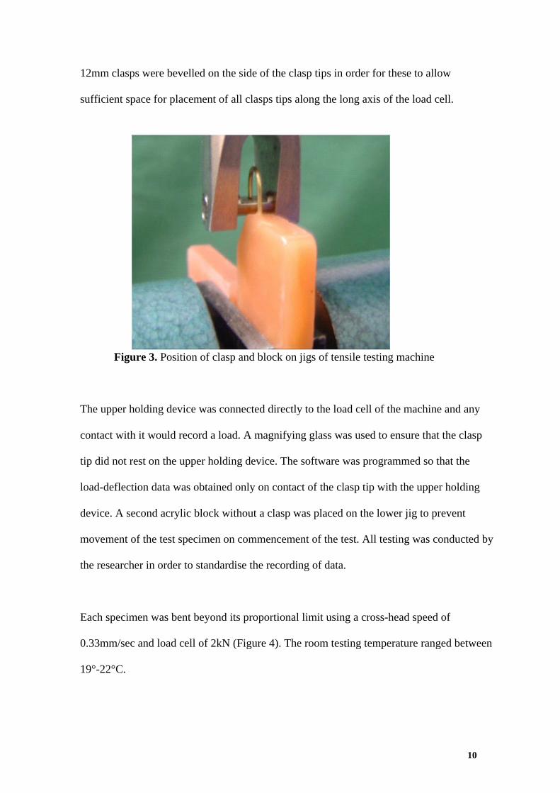
12mm clasps were bevelled on the side of the clasp tips in order for these to allow
sufficient space for placement of all clasps tips along the long axis of the load cell.
Figure 3. Position of clasp and block on jigs of tensile testing machine
The upper holding device was connected directly to the load cell of the machine and any
contact with it would record a load. A magnifying glass was used to ensure that the clasp
tip did not rest on the upper holding device. The software was programmed so that the
load-deflection data was obtained only on contact of the clasp tip with the upper holding
device. A second acrylic block without a clasp was placed on the lower jig to prevent
movement of the test specimen on commencement of the test. All testing was conducted by
the researcher in order to standardise the recording of data.
Each specimen was bent beyond its proportional limit using a cross-head speed of
0.33mm/sec and load cell of 2kN (Figure 4). The room testing temperature ranged between
19°-22°C.
10
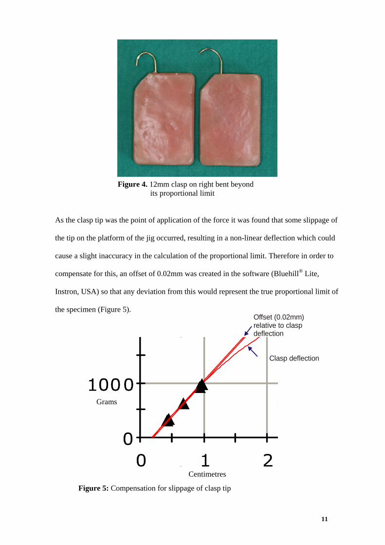
Figure 4. 12mm clasp on right bent beyond its proportional limit
Offset (0.02mm)relative to claspdeflection
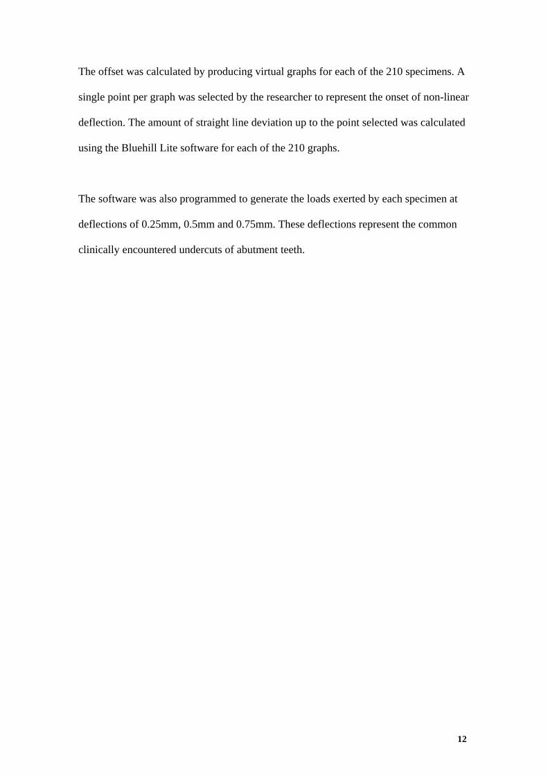
As the clasp tip was the point of application of the force it was found that some slippage of
the tip on the platform of the jig occurred, resulting in a non-linear deflection which could
cause a slight inaccuracy in the calculation of the proportional limit. Therefore in order to
compensate for this, an offset of 0.02mm was created in the software (Bluehill® Lite,
Instron, USA) so that any deviation from this would represent the true proportional limit of
the specimen (Figure 5).
Clasp deflection
Grams
Centimetres
Figure 5: Compensation for slippage of clasp tip
11
The offset was calculated by producing virtual graphs for each of the 210 specimens. A
single point per graph was selected by the researcher to represent the onset of non-linear
deflection. The amount of straight line deviation up to the point selected was calculated
using the Bluehill Lite software for each of the 210 graphs.
The software was also programmed to generate the loads exerted by each specimen at
deflections of 0.25mm, 0.5mm and 0.75mm. These deflections represent the common
clinically encountered undercuts of abutment teeth.
12
13
3. RESULTS
None of the samples fractured during testing, nor did any of the wires become loose from
the acrylic blocks.
The forces for each of the 210 samples were analysed statistically using the Statistical
Package and Service Solutions (SPSS Inc, Chicago, USA). This was done in order to
reduce each batch to a representative value for ease of analysis. Both parametric
(Kolmogorov-Smirnov Z) and non-parametric tests (Exact Method) confirmed that the data
were normally distributed and consistent. Therefore the mean values were used to analyse
each batch of samples. The standard deviations of the batches were similar and therefore
the data were considered to be consistent.
A retentive clasp is required to behave elastically in clinical situations, i.e. within its
proportional limit (Bates 1965, Frank and Nicholls 1986). Bates (1965) suggested that a
reason for the failure of clasps clinically was that they may have functioned too close to
their proportional limits. He suggested that retentive clasps should function within two
standard deviations from their proportional limit, which he termed the “realistic limit”.
Therefore the realistic limit of each wire was calculated (Table 2). From these data, a table
was then derived to show whether the wires functioned within their realistic limits at
0.25mm, 0.5mm and 0.75mm deflections respectively for the different lengths representing
premolars and molars (Table 3).
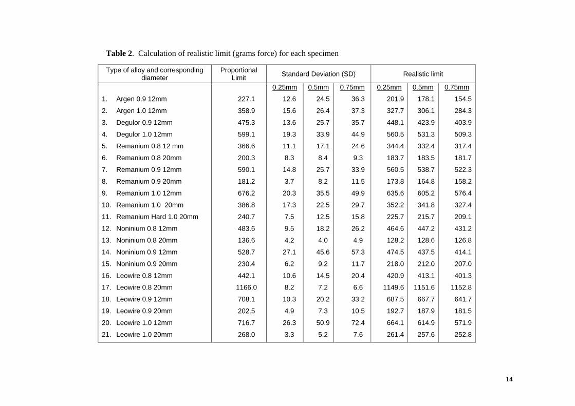
Table 2. Calculation of realistic limit (grams force) for each specimen
Type of alloy and corresponding diameter
Proportional Limit Standard Deviation (SD) Realistic limit
1. Argen 0.9 12mm
2. Argen 1.0 12mm
3. Degulor 0.9 12mm
4. Degulor 1.0 12mm
5. Remanium 0.8 12 mm
6. Remanium 0.8 20mm
7. Remanium 0.9 12mm
8. Remanium 0.9 20mm
9. Remanium 1.0 12mm
10. Remanium 1.0 20mm
11. Remanium Hard 1.0 20mm
12. Noninium 0.8 12mm
13. Noninium 0.8 20mm
14. Noninium 0.9 12mm
15. Noninium 0.9 20mm
16. Leowire 0.8 12mm
17. Leowire 0.8 20mm
18. Leowire 0.9 12mm
19. Leowire 0.9 20mm
20. Leowire 1.0 12mm
21. Leowire 1.0 20mm
227.
1
9
3
1
6
3
1
2
2
8
7
6
6
7
4
1
0
1
5
7
0
358.
475.
599.
366.
200.
590.
181.
676.
386.
240.
483.
136.
528.
230.
442.
1166.
708.
202.
716.
268.
0.25mm
12.6
15.6
13.6
19.3
11.1
8.3
14.8
3.7
20.3
17.3
7.5
9.5
4.2
27.1
6.2
10.6
8.2
10.3
4.9
26.3
3.3
0.5mm
24.5
26.4
25.7
33.9
17.1
8.4
25.7
8.2
35.5
22.5
12.5
18.2
4.0
45.6
9.2
14.5
7.2
20.2
7.3
50.9
5.2
0.75mm
36.3
37.3
35.7
44.9
24.6
9.3
33.9
11.5
49.9
29.7
15.8
26.2
4.9
57.3
11.7
20.4
6.6
33.2
10.5
72.4
7.6
0.25mm
201.9
327.7
448.1
560.5
344.4
183.7
560.5
173.8
635.6
352.2
225.7
464.6
128.2
474.5
218.0
420.9
1149.6
687.5
192.7
664.1
261.4
0.5mm
178.1
306.1
423.9
531.3
332.4
183.5
538.7
164.8
605.2
341.8
215.7
447.2
128.6
437.5
212.0
413.1
1151.6
667.7
187.9
614.9
257.6
0.75mm
154.5
284.3
403.9
509.3
317.4
181.7
522.3
158.2
576.4
327.4
209.1
431.2
126.8
414.1
207.0
401.3
1152.8
641.7
181.5
571.9
252.8
14
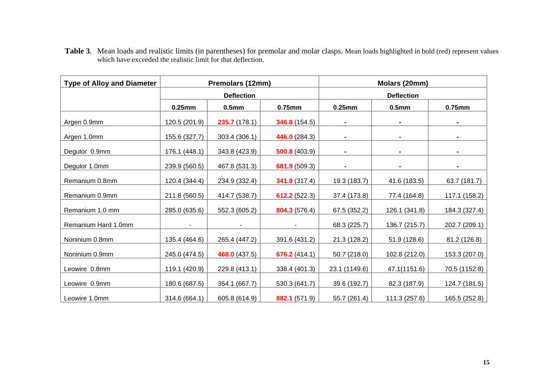
Table 3. Mean loads and realistic limits (in parentheses) for premolar and molar clasps. Mean loads highlighted in bold (red) represent values which have exceeded the realistic limit for that deflection.
Type of Alloy and Diameter Premolars (12mm) Molars (20mm)
Deflection Deflection
0.25mm 0.5mm 0.75mm 0.25mm 0.5mm 0.75mm
Argen 0.9mm 120.5 (201.9) 235.7 (178.1) 346.8 (154.5) - - -
Argen 1.0mm 155.6 (327.7) 303.4 (306.1) 446.0 (284.3) - - -
Degulor 0.9mm 176.1 (448.1) 343.8 (423.9) 500.8 (403.9) - - -
Degulor 1.0mm 239.9 (560.5) 467.8 (531.3) 681.9 (509.3) - - -
Remanium 0.8mm 120.4 (344.4) 234.9 (332.4) 341.9 (317.4) .7) 19.3 (183.7) 41.6 (183.5) 63.7 (181
Remanium 0.9mm 211.8 (560.5) 414.7 (538.7) 612.2 (522.3) .2) 37.4 (173.8) 77.4 (164.8) 117.1 (158
Remanium 1.0 mm 285.0 (635.6) 552.3 (605.2) 804.3 (576.4) ) .4) 67.5 (352.2) 126.1 (341.8 184.3 (327
Remanium Hard 1.0mm - - - 68.3 (225.7) 136.7 (215.7) .1) 202.7 (209
Noninium 0.8mm 135.4 (464.6) 265.4 (447.2) 391.6 (431.2) .8) 21.3 (128.2) 51.9 (128.6) 81.2 (126
Noninium 0.9mm 245.0 (474.5) 468.0 (437.5) 676.2 (414.1) ) .0) 50.7 (218.0) 102.8 (212.0 153.3 (207
Leowire 0.8mm 119.1 (420.9) 229.8 (413.1) 338.4 (401.3) ) 23.1 (1149.6) 47.1(1151.6) 70.5 (1152.8
Leowire 0.9mm 180.6 (687.5) 354.1 (667.7) 530.3 (641.7) .5) 39.6 (192.7) 82.3 (187.9) 124.7 (181
Leowire 1.0mm 314.6 (664.1) 605.8 (614.9) 882.1 (571.9) ) .8) 55.7 (261.4) 111.3 (257.6 165.5 (252
15

Analyses of the results in Table 3 were as follows:
1. All the 12mm (premolar) clasps were within their respective realistic limits at
0.25mm deflections. Argen 0.9mm and Noninium 0.9mm exceeded their
respective realistic limits at 0.5mm deflections.
2. Noninium clasps (0.8mm) together with Leowire (0.8mm and 0.9mm) were the
only premolar clasps to record mean loads within their respective realistic limits at
a deflection of 0.75mm.
3. All the 20mm (molar) clasps were within their respective realistic limits for all
three deflections.
4. Increases in diameter and undercut resulted in higher loads being recorded for
each of the respective wires.
5. Remanium Hard 1.0mm wire produced higher loads at similar deflections
compared with Remanium 1.0mm wire.
A one-way Analysis of Variance (ANOVA) test was used to identify significant
differences in the distribution of data related to the following:
1. Comparison of 0.8mm and 0.9mm diameters of Noninium, Leowire and
Remanium wires for lengths 12mm and 20mm respectively.
2. The behaviour of the stainless steel versus gold alloys
The one-way ANOVA was chosen on the basis that the following assumptions were
upheld (Norusis 1993):
1. Each of the groups was an independent random sample.
2. The data indicated a normal distribution.
3. The variances of the groups were equal.
16
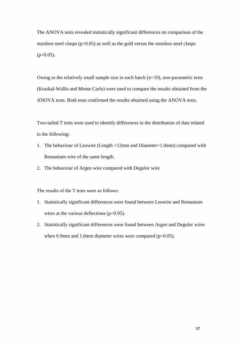
The ANOVA tests revealed statistically significant differences on comparison of the
stainless steel clasps (p<0.05) as well as the gold versus the stainless steel clasps
(p<0.05).
Owing to the relatively small sample size in each batch (n=10), non-parametric tests
(Kruskal-Wallis and Monte Carlo) were used to compare the results obtained from the
ANOVA tests. Both tests confirmed the results obtained using the ANOVA tests.
Two-tailed T tests were used to identify differences in the distribution of data related
to the following:
1. The behaviour of Leowire (Length =12mm and Diameter=1.0mm) compared with
Remanium wire of the same length.
2. The behaviour of Argen wire compared with Degulor wire
The results of the T tests were as follows:
1. Statistically significant differences were found between Leowire and Remanium
wires at the various deflections (p<0.05).
2. Statistically significant differences were found between Argen and Degulor wires
when 0.9mm and 1.0mm diameter wires were compared (p<0.05).
17
4. DISCUSSION
Although the clasp behaviour was statistically consistent for each of the batches of
each of the wires, variations did exist in the forces applied at different deflections, and
in the proportional limits, indicating that there are inconsistencies, presumably as a
result of the manufacturing process. Hence Bates’ (1965, 1968) contention that a
realistic limit be used still has merit.
Clayton and Jaslow (1971) reported that the length of a wrought wire clasp was not a
significant factor related to its flexibility. In the present study, however, all the 20 mm
(molar clasps) produced lower loads compared with the 12mm (premolar clasps) for
all three depths of undercuts respectively (Table 3). An increase in the diameter of
wrought wire clasps, from 0.8mm to 1.0mm, has been reported to produce higher
loads at deflections of 0.25mm and 0.5mm respectively (Frank and Nicholls 1981).
The findings of the present study for molar clasps are in agreement with this.
Caldwell (1962) measured the adhesiveness of various types of foods, by measuring
the amount of force per area required to dislodge the food when held between two
flattened enamel surfaces. Bates (1963) employed a similar method and calculated
that the bond strength required to dislodge a sticky toffee held between two porcelain
plates was 1kg/cm2. In the same study Bates combined this bond strength with the
total surface area of a premolar and two molars in order to calculate the force required
to dislodge a unilateral distal extension RPD replacing three teeth. This was calculated
to be 2600g, on the basis that the maximum displacing force on an RPD occurred
when the teeth had penetrated the food followed by the jaw being opened after 0.5
seconds. Bates used the findings by Caldwell (1962) and calculated that the force
required to retain a unilateral distal extension RPD replacing three teeth would range
18
from 850g to 1500g for “normal foods” (cornflakes, mashed potato, bread and butter).
A literature search revealed no similar studies to confirm the amount of time and force
required to dislodge an RPD whilst eating.
Frank and Nicholls (1981) used a tensile testing machine to measure the forces
required to remove five distal extension base RPDs when round wrought wire clasps
were placed in both 0.01”(0.25mm) and 0.015” (0.38mm) undercuts of premolars.
They reported that 300 to 750 grams (150 to 375 grams per clasp) of force represented
effective retention for a mandibular bilateral distal extension RPD. The displacing
force in that study was directed toward the centre of the RPD in each case and each
RPD was removed along its path of insertion. However the direction, magnitude and
point of application of forces on RPDs are very different clinically, especially when
RPDs are subjected to forces other than those along their path of insertion or removal.
Therefore it is likely that forces in excess of 750 grams, as mentioned by Bates
(1963), could be required to retain distal extension base RPDs.
Passive retention produced by guideplanes in the tooth-supported RPD scenario,
would assist the retention from clasps to a greater extent in the bounded saddle, with
two guideplanes per saddle compared with only one in a distal extension base.
Therefore the retentive force required will be greater in a distal extension base, than
for a bounded saddle.
The above studies seem, therefore, to have made recommendations for the desired
retention from clasps to be in a wide range of 300g to 2600g. In order to produce
effective clinical guidelines for the choice of clasps for RPDs, it would seem
19
20
reasonable to define a minimum force required from clasps. There appear to be no
previous studies providing information on the ability of abutment teeth to withstand
forces from clasps. However, in vivo occlusal forces have been reported to range from
200 Newtons (20 387g) to 450 Newtons (45 871g) on average during normal function
(Worthington, Lang and Rubenstein 2003). It is clear from these values that teeth are
able to withstand high forces as a result of the physiological behaviour of the
periodontal ligament. The maximum forces recorded for all clasps in the current
study, below their realistic limits, are therefore well within the capacity of the
periodontium.
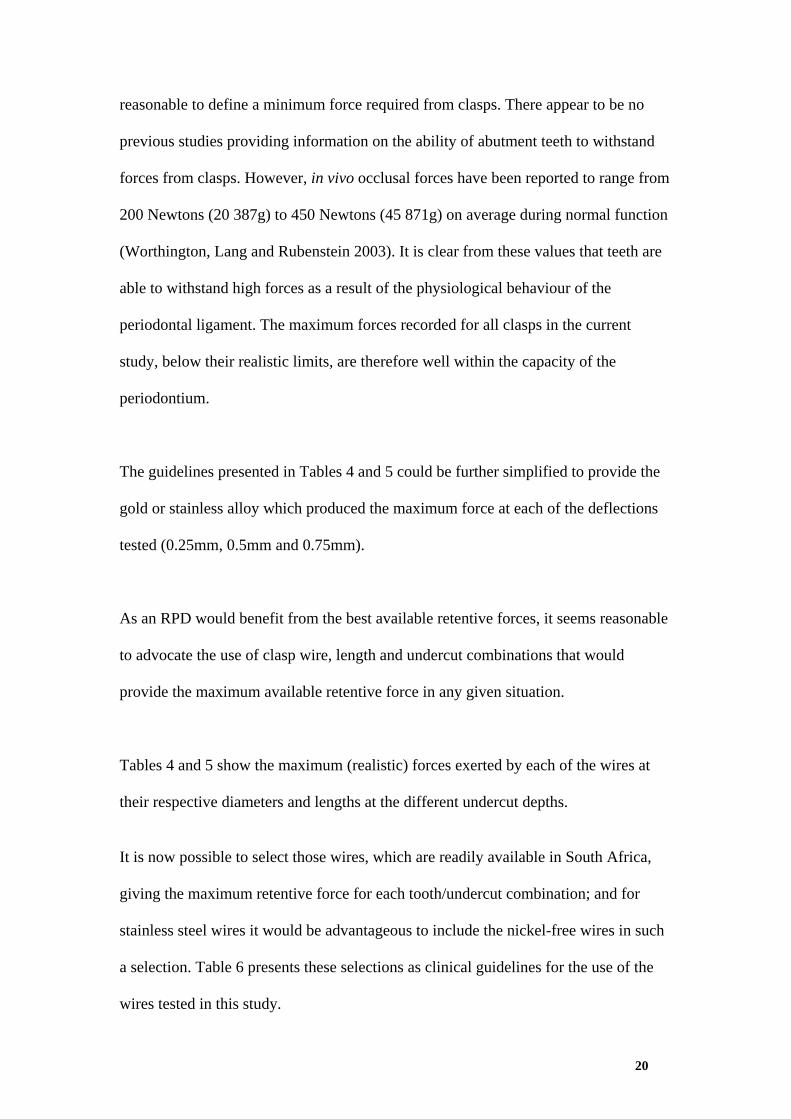
The guidelines presented in Tables 4 and 5 could be further simplified to provide the
gold or stainless alloy which produced the maximum force at each of the deflections
tested (0.25mm, 0.5mm and 0.75mm).
As an RPD would benefit from the best available retentive forces, it seems reasonable
to advocate the use of clasp wire, length and undercut combinations that would
provide the maximum available retentive force in any given situation.
Tables 4 and 5 show the maximum (realistic) forces exerted by each of the wires at
their respective diameters and lengths at the different undercut depths.
It is now possible to select those wires, which are readily available in South Africa,
giving the maximum retentive force for each tooth/undercut combination; and for
stainless steel wires it would be advantageous to include the nickel-free wires in such
a selection. Table 6 presents these selections as clinical guidelines for the use of the
wires tested in this study.
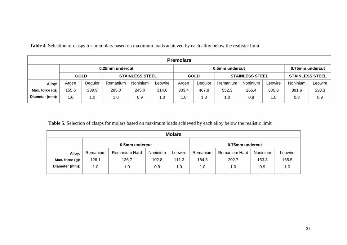
Table 4. Selection of clasps for premolars based on maximum loads achieved by each alloy below the realistic limit
Premolars
0.25mm undercut 0.5mm undercut 0.75mm undercut
GOLD STAINLESS STEEL GOLD STAINLESS STEEL STAINLESS STEEL
Alloy: Max. force (g):
Diameter (mm):
Argen
155.6
1.0
Degulor
239.9
1.0
Remanium
285.0
1.0
Noninium
245.0
0.9
Leowire
314.6
1.0
Argen
303.4
1.0
Degulor
467.8
1.0
Remanium
552.3
1.0
Noninium
265.4
0.8
Leowire
605.8
1.0
Noninium
391.6
0.8
Leowire
530.3
0.9
Table 5. Selection of clasps for molars based on maximum loads achieved by each alloy below the realistic limit
Molars
0.5mm undercut
0.75mm undercut
Alloy: Max. force (g):
Diameter (mm):
Remanium
126.1
1.0
Remanium Hard
136.7
1.0
Noninium
102.8
0.9
Leowire
111.3
1.0
Remanium
184.3
1.0
Remanium Hard
202.7
1.0
Noninium
153.3
0.9
Leowire
165.5
1.0
21
22
Premolars Molars
0.25mm 0.5mm 0.75mm 0.5mm 0.75mm
Gold Stainless Steel Gold Stainless Steel Stainless Steel Stainless Steel Stainless Steel
Clasp (force in grams)
Degulor 1.0mm (239.9)
Leowire 1.0mm (314.6)
Degulor 1.0mm (467.8)
Leowire 1.0mm (605.8)
Leowire 0.9mm (530.3)
Remanium Hard 1.0mm (136.7)
Remanium Hard 1.0mm (202.7)
For nickel
sensitive patients
Noninium 0.9mm (245.0) Noninium 0.8mm
(265.4) Noninium 0.8mm
(391.6) Noninium 0.9mm
(102.8) Noninium 0.9mm
(153.3)
Table 6. Clasp selection for premolars and molars based on maximum loads exerted.
5. CONCLUSION AND RECOMMENDATIONS
5.1 Conclusion
Whilst metal-based RPDs have the benefits of providing adequate comfort and fit
with limited coverage of soft tissues, previous research has shown that cast clasps
with short retentive arms may not function adequately and are prone to fracture (Bates
1965).
Acrylic-based RPDs are more cost-effective than metal-based frameworks, and if
designed correctly, can be regarded as permanent prostheses for those patients who
cannot afford metal bases. However, poor selection and construction of wrought wires
used for their fabrication could result in poor adaptation to abutment teeth, loss of
adaptation over a period of time, and potential fracture (Frank 1986). Therefore, it
was felt that an understanding of the behaviour of readily available round wrought
wires used in the fabrication of acrylic RPDs, in South Africa, would be beneficial.
Such data would also be beneficial for short retentive clasps in metal-based dentures.
Within the limitations of this study, it has been shown that round wrought wire clasp
selection is influenced by alloy type, diameter, length and undercut depth. On the
assumption that maximum retention from clasps is desirable for an RPD, guidelines
have been produced for the use of the wrought wires available for various clinical
scenarios.
23
5.2 Recommendations
Within the limitations of this study, the following recommendations are made:
• The guidelines produced for the wires used for this study are based on the
maximum forces obtained. Generally, only one clasp per side of the arch should
provide adequate active retention, except in tooth-supported bases with long
spans. However, clasps were tested for premolars and molars only. Future
research could employ a similar method to this study to obtain load-deflection
data for canine teeth.
• Wire diameters greater than 1.0mm could be tested using a similar method to
produce higher loads for molar clasps compared with those reported in this study.
• For patients with allergies to nickel, the Noninium 0.8mm diameter round wrought
wire clasp could be placed in both 0.5mm and 0.75mm undercuts on premolars,
and the Noninium 0.9mm wire can be placed in a 0.75mm undercut of a molar.
• The results of this study have shown that, for 0.9mm and 1.0mm diameters of
wires, statistically significant differences exists between the gold and stainless
steel round wrought wire clasps. However, the large cost difference between these
alloys suggests that the only advantage of using gold alloy wire on premolars
would be for the cosmetic value.
• Studies are required to investigate the forces required to retain both tooth-
supported and distal extension RPDs and the ability of abutment teeth to withstand
these forces.
• Studies are required to assess the effects of other factors such as guide plane
retention and paths of withdrawal on the overall retention of an RPD.
24
6. REFERENCES
Bates JF. Retention of cobalt-chromium partial dentures. Dent Practit Dent Rec 1963;
14:168-171.
Bates JF. The mechanical properties of the cobalt-chromium alloys and their relation
to partial denture design. Br Dent J 1965; 119:389-296.
Bates JF. Studies on the retention of cobalt-chromium partial dentures. Br Dent J
1968; 125:97-102.
Brudvick JS, Morris HF. Stress-relaxation testing. Part III: Influence of wire alloys,
gauges, and lengths on clasp behaviour. J Prosthet Dent 1981; 46:374-379.
Brudvick JS, Wormley JH. Construction techniques for wrought-wire retentive clasp
arms as related to clasp flexibility. J Prosthet Dent 1973; 30:769-774.
Caldwell RC. Adhesion of foods to teeth. J Dent Res 1962; 41:821-832.
Clayton JA, Jaslow C. A measurement of clasp forces on teeth. J Prosthet Dent 1971;
25:21-43.
Craig RG, Ward ML. Restorative dental materials. 10th ed. St Louis: Mosby. 1997:Pp
209-350.
25
David A, Lobner D. In vitro cytotoxicity of orthodontic archwires in cortical cell
cultures. Eur J Orthodontics 2004; 26: 421-426.
Frank RP, Nicholls JI. A Study of the flexibility of wrought wire clasps. J Prosthet
Dent 1981; 45:259-267.
Frank RP. Direct retainers for distal-extension removable partial dentures. J Prosthet
Dent 1986; 56:562-567.
Goolam R. The selection of wrought wire clasps for removable partial dentures.
Unpublished research report 1992, University of the Western Cape.
Matheson GR, Brudvik JS, Nicholls JI. Behavior of wrought wire clasps after
repeated permanent deformation. J Prosthet Dent 1986; 55:226-231.
Montanaro L, Cervellati M, Campoccia D, Prati C, Breschi L, Arciola CR. No
genotoxicity of a new nickel-free stainless steel. Int J Artif organs 2005; 28:58-65.
Morais S, Sousa JP, Fernandes MH, Carvalho GS, de Bruin JD, van Blitterswijk CA.
Decreased consumption of Ca and P during in vitro biomineralization and biologically
induced deposition of Ni and Cr in presence of stainless steel corrosion products. J
Biomed Mater Res 1998; 42:199-212.
26
Morris HF, Asgar K, Brudvick JS, Winkler S, Roberts EP. Stress-relaxation testing,
Part IV: Clasp pattern dimensions and their influence on clasp behaviour. J Prosthet
Dent 1983; 50:319-326.
Norusis, MJ. SPSS for Windows. User’s guide release 6.0. Chicago: SPSS Inc. 1993:
Pp 249-266.
Owen CP. Fundamentals of removable partial dentures. 2nd Ed. Cape Town: UCT
Press. 2000: Pp 25-84.
Platt JA, Guzman A, Zuccari A, Thornberg DW, Rhodes BF, Oshida Y et al.
Corrosion behaviour of 2205 duplex stainless steel. Am J Orthod Dentofacial Orthop
1997; 112: 69-79.
Pourbaix M. Electrochemical corrosion of metallic biomaterials. Biomaterials 1984;
5:122-134.
Shih CC, Shih CM, Chen YL, Su Y-Y, Shih JS, Kwok C-F, et al. Growth inhibition of
cultured smooth muscle cells by corrosion products of 316L stainless steel wire. J
Biomed Mater Res 2001; 57:200-207.
Shirasu K, Wakabayashi N, Yoneyama T, Igarashi Y. Non-linear finite element stress
analysis of plastic deformation in Co-Cr wrought-wire clasps. Dent Mater 2008;
24:1518-1524.
27
28
Schubert H, Prater E. Nickel-dermatitis - a follow-up study. Br J Dermatol 1987; 117:
43; cited in Platt et al. 1997.
Stobie J. Comparison of the deflection characteristics of typical removable partial
denture clasps. Thesis, University of Texas Dental Branch, 1969, cited in Frank and
Nicholls 1981.
VandenBrink JP, Wolfaardt JF, Faulkner GM. A comparison of various removable
partial denture clasp materials and fabrication procedure for placing clasps on canine
and premolar teeth. J Prosthet Dent 1993; 70:180-8.
Waldmeier MD, Grasso JE, Norberg GJ, Nowak MD. Bend testing of wrought wire
removable partial denture alloys. J Prosthet Dent 1996; 76: 559-65.
Warr JA. An analysis of clasp design in partial dentures. Phys Med Biol 1959; 3:212-
232.
Warr JA. Numerical system of clasp design. J Prosthet Dent 1961; 11:1105-1111.
Worthington P, Lang B & Rubenstein J. Osseointegration in Dentistry. An Overview.
Second Edition. Quintessence, Chicago, 2003:56-59.