Embed Size (px)
Citation preview

Guidelines for the Design of Critical Communications Circuits
WECC Guideline
Telecommunications Work Group
February 7, 2017
155 North 400 West, Suite 200
Salt Lake City, Utah 84103-1114

Guidelines for the Design of Critical Communications Circuits ii
W E S T E R N E L E C T R I C I T Y C O O R D I N A T I N G C O U N C I L
Table of Contents
1. Purpose .................................................................................................................................... 1
2. Scope ....................................................................................................................................... 1
3. Overview .................................................................................................................................. 1
4. Abbreviations and Acronyms .................................................................................................... 2
5. Facilities ................................................................................................................................... 4
5.1 General ....................................................................................................................................... 4
5.2 Building Structures ..................................................................................................................... 4
5.3 Towers ........................................................................................................................................ 5
5.4 Electrical and Grounding ............................................................................................................ 5
5.4.1 Ground Potential Rise and Lightning .............................................................................. 5
5.4.2 Building Electrical and Power Systems ........................................................................... 5
5.5 Power .......................................................................................................................................... 5
5.5.1 Equipment Power ........................................................................................................... 5
5.5.2 Communications Batteries ............................................................................................. 5
5.5.3 Battery Sizing .................................................................................................................. 6
5.5.4 Battery Recharge ............................................................................................................ 6
5.5.5 Monitoring ...................................................................................................................... 6
5.5.6 Generators ...................................................................................................................... 6
5.6 Security and Monitoring ............................................................................................................. 7
6 Communications Cables ............................................................................................................ 7
6.1 General ....................................................................................................................................... 7
6.2 Metallic Cables ........................................................................................................................... 7
6.2.1 Electrical Substations ..................................................................................................... 7
6.2.2 Communications Facilities .............................................................................................. 9
6.3 Fiber-Optic Cables ...................................................................................................................... 9
6.3.1 Outside Plant .................................................................................................................. 9
6.3.2 Inside Plant ................................................................................................................... 10
Guidelines for the Design of Critical Communications Circuits iii
W E S T E R N E L E C T R I C I T Y C O O R D I N A T I N G C O U N C I L
6.4 Physical Diversity ...................................................................................................................... 10
7 Transport Design .................................................................................................................... 10
7.1 General ..................................................................................................................................... 10
7.1.1 Equipment .................................................................................................................... 10
7.2 Multiplex Systems .................................................................................................................... 11
7.2.1 Frequency Division ....................................................................................................... 11
7.2.2 Time Division ................................................................................................................ 11
7.2.3 Packet ........................................................................................................................... 11
7.3 Microwave Systems .................................................................................................................. 11
7.3.1 Licensed, Unlicensed, and Registered .......................................................................... 11
7.3.2 Path Engineering .......................................................................................................... 11
7.4 Fiber-Optic Systems .................................................................................................................. 12
7.4.1 Optical Budget Engineering .......................................................................................... 12
7.5 Packet Switched Systems ......................................................................................................... 12
7.5.1 Gather information....................................................................................................... 13
7.5.2 Use the information gathered above to design the network. ..................................... 15
7.6 Power-Line Carrier Systems ..................................................................................................... 17
7.6.1 Coordination ................................................................................................................. 17
7.6.2 System Engineering ...................................................................................................... 17
7.7 Telco Leased Lines for Transport .............................................................................................. 17
7.8 Satellite Systems ....................................................................................................................... 17
7.9 Monitoring ................................................................................................................................ 17
8 Circuit Design, Testing, and Monitoring ................................................................................... 17
8.1 General ..................................................................................................................................... 17
8.2 Analog Circuits .......................................................................................................................... 18
8.2.1 Balanced Pairs .............................................................................................................. 18
8.2.2 Analog Signal via Analog Microwave Systems ............................................................. 18
8.2.3 Analog Data Circuit Parameters ................................................................................... 18
Guidelines for the Design of Critical Communications Circuits iv
W E S T E R N E L E C T R I C I T Y C O O R D I N A T I N G C O U N C I L
8.2.4 Analog Circuits Over Digital Systems ............................................................................ 18
8.3 Digital Circuits ........................................................................................................................... 19
8.3.1 Compatibility Considerations ....................................................................................... 19
8.3.2 Testing Standards ......................................................................................................... 19
8.3.3 Error Types and Analysis .............................................................................................. 19
8.3.4 Monitoring .................................................................................................................... 20
8.4 Packet Circuits .......................................................................................................................... 20
8.4.1 General Nature ............................................................................................................. 20
8.4.2 Testing Standards ......................................................................................................... 21
8.4.3 Error Types ................................................................................................................... 21
8.4.4 Monitoring .................................................................................................................... 22
9 Critical Circuit Availability Calculation Methodology ............................................................... 22
9.1 Introduction .............................................................................................................................. 22
9.2 Reliability Terms and Symbols .................................................................................................. 22
9.3 Other Acronyms ....................................................................................................................... 23
9.4 Methodology ............................................................................................................................ 24
9.5 Availability Input Parameters ................................................................................................... 25
9.6 Availability Calculations ............................................................................................................ 27
9.7 References ................................................................................................................................ 32
Guidelines for the Design of Critical Communications Circuits 1
W E S T E R N E L E C T R I C I T Y C O O R D I N A T I N G C O U N C I L
1. Purpose
These guidelines provide communications system designers with the basic design requirements for
communications circuits that carry protective relaying, Remedial Action Schemes (RAS), or other
critical communications traffic. Also included is the design of communication facilities that will
ensure the performance of communication circuits. These guidelines may be used as a resource of
collective knowledge and to clarify specific requirements set forth by the Communications System
Performance Guide for Electric Protection Systems document.
2. Scope
Communications circuits that are used for critical traffic must perform during all power system
operations and weather conditions. This document addresses the design considerations and
requirements for circuits that are used for these or similar purposes, as well as a variety of other
types of circuits. This document can be used to interpret what can be done to bring
communications circuits into compliance with the policies set forth by the Western Electricity
Coordinating Council (WECC).
3. Overview
It is crucial that critical communications circuits perform as required. Since most communication
equipment is not substation hardened, it is susceptible to electrical, electro-magnetic, and
associated noise. Therefore, special precautions must be taken when designing, installing, and
operating this equipment.
The Communications System Performance Guide for Electric Protection Systems document sets
forth requirements of performance for four protection application levels of communications
circuits. For clarification of availability requirements of the four levels of circuits, refer to Table 2 of
that document. For critical circuit availability calculation methodology, please see Section 9 of this
document.
Please note that all standards and recommendations referred to in these guidelines will be the
latest version in effect at time of design. Existing systems designed to previous versions of
referenced standards and recommendations will not be required to conform to the latest version.
Guidelines for the Design of Critical Communications Circuits 2
W E S T E R N E L E C T R I C I T Y C O O R D I N A T I N G C O U N C I L
4. Abbreviations and Acronyms
A .....................Availability
AC ...................Alternating Current
ADM ...............Add/Drop Multiplexer
ADSS ...............All-Dielectric Self Supporting
ANSI ................American National Standards Institute
ATM ................Asynchronous Transfer Mode
BER .................Bit Error Rate
BICSI ...............Building Industry Consulting Service International
BIL ...................Basic Impulse Insulation Level
CB ...................Channel Bank
CSU/DSU .........Channel Service Unit / Data Service Unit
DC ...................Direct Current
DCS .................Digital Cross-connect System
DS-0 ................Digital Signal level 0
DS-1 ................Digital Signal level 1
EB ...................Errored Blocks
EDFA ...............Erbium Doped Fiber Amplifier
EIA/TIA ...........Electronic Industries Alliance / Telecommunications Industry Association
EM ..................Errored Minutes
ES ....................Errored Seconds
ESD .................ElectroStatic Discharge
ESR ..................Errored Seconds Ratio
FIT ...................Failures In Time
GPR .................Ground Potential Rise
IEC ..................International Electrotechnical Commission
IEEE .................Institute of Electrical and Electronics Engineers
IP ....................Internet Protocol

Guidelines for the Design of Critical Communications Circuits 3
W E S T E R N E L E C T R I C I T Y C O O R D I N A T I N G C O U N C I L
ITU ..................International Telecommunication Union
kBPS ................kiloBits Per Second
kV ...................kiloVolt
LOF .................Loss of Frame
LOS .................Loss of Signal
MOV ...............Metal Oxide Varistor
MPLS...............MultiProtocol Label Switching
MTBF ..............Mean Time Before Failure, also Mean Time Between Failure
MTR ...............Mean Time to Restore
MTTR ..............Mean Time to Repair
MW .................MicroWave
NEBS ...............Network Equipment Building System
NECA...............National Electrical Contractors Association
NESC ...............National Electric Safety Code
NMS ................Network Management System
OC-3 ...............Optical Carrier level 3
OOF ................Out of Frame
OPGW .............Optical Ground Wire
PPE .................Personal Protective Equipment
QOS ................Quality of Service
RAS .................Remedial Action Scheme
RF....................Radio Frequency
RFI...................Radio Frequency Interference
RMS ................Root Mean Square
SD ...................Space Diversity
SES ..................Severely Errored Seconds
SESR ................Severely Errored Seconds Ratio
SONET .............Synchronous Optical NETwork

Guidelines for the Design of Critical Communications Circuits 4
W E S T E R N E L E C T R I C I T Y C O O R D I N A T I N G C O U N C I L
STP ..................Shielded Twisted Pair
SWC ................Surge Withstand Capability
Telco ...............Telephone Company
TT ....................Transfer Trip
U .....................Unavailability
UTC .................Utilities Telecom Council
UTP .................Unshielded Twisted Pair
VF ...................Voice Frequency
VT1.5 ..............Virtual Tributary level 1.5
WECC ..............Western Electric Coordinating Council
......................Failure rate per hour
......................Restore rate per hour
5. Facilities General
Due to the vital nature of protection circuits, all telecommunications facilities that support
critical communications circuits will be designed and maintained to WECC Criteria, NERC
Standards, and other industry standards listed in this document. Design elements will consider
risks due to severe storms, lightning, fire, flooding, geological disaster, vandalism, electrical
disturbances, etc.
5.2 Building Structures
All buildings will comply with Telcordia Standard GR-43-CORE, Generic Requirements for
Telecommunications Huts; specifically, the following sections:
Section 3.18.4 ............Air-conditioning and Heating Systems
Section 3.22................Structural
Section 3.23................Impact Resistance
Section 3.28................Weather Resistance
Section 3.30................Earthquake Resistance
Guidelines for the Design of Critical Communications Circuits 5
W E S T E R N E L E C T R I C I T Y C O O R D I N A T I N G C O U N C I L
5.3 Towers
All towers and support structures for microwave transmission antennas will meet the design
criteria of EIA/TIA-222. Any structural modifications or antenna changes will require design
review to ensure compliance with EIA/TIA-222 criteria.
5.4 Electrical and Grounding
5.4.1 Ground Potential Rise and Lightning
Lightning/Ground Potential Rise (GPR) surge arresters will be provided at the AC service
entrance or in the charger itself. The avalanche-type device arresters are recommended. These
avalanche-type semiconductors respond quickly and, if not destroyed, will not degrade with
each successive lightning strike; as do Metal Oxide Varistor (MOV) devices.
5.4.2 Building Electrical and Power Systems
All building, electrical, and power systems will comply with the following:
IEEE Standard 1100 Recommended Practice for Powering and Grounding Electronic
Equipment.
Motorola Standard R-56 (Chapters 4 and 5, External and Internal Grounding).
5.5 Power
5.5.1 Equipment Power
All equipment used for critical circuits will be powered from a DC Power Plant with battery
backup. Design criteria should include N+1 redundancy for electronic components, such that no
single component failure will result in a critical communications circuit outage.
5.5.2 Communications Batteries
Unless the communications equipment is substation-hardened, it must have its own DC power
system, supplied by a separate battery. Large transients can be induced on the substation
battery DC bus during a fault resulting from the operation of substation equipment
(opening/closing switches or breakers, etc.). Typically, power line carrier communications
equipment is powered by the substation battery because it is hardened. For equipment to be
substation-hardened, it must be tolerant to a variety of destructive electrical quantities.
Substation-hardened equipment must meet the following requirements:
ANSI PC37.90.2 (35 Volts/Meter)
IEC 255-22-3 (RFI Class III)
Guidelines for the Design of Critical Communications Circuits 6
W E S T E R N E L E C T R I C I T Y C O O R D I N A T I N G C O U N C I L
ANSI C37.90 (Dielectric)
ANSI C37.90.1 (SWC and Fast Transient)
IEC 255-5 (1500 Vrms Breakdown Voltage and Impulse Withstand)
IEC 255-22-1 (SWC Class III)
IEC 255-22-2 (ESD Class III)
IEC 255-22-4 (Fast-Transient Class III)
IEC 60834-1 (Teleprotection Equipment Performance)
IEEE Standard. 1613 (Standards for Communications Networks in Substations)
To ensure reliable operation, battery plants will receive regular maintenance and testing.
Battery system design should take into account IEEE Standard 1375 “IEEE Guide for the
Protection of Stationary Battery Systems.”
5.5.3 Battery Sizing
Accessibility and travel time to the communications site is to be taken into account when sizing
the battery. In all cases, the battery will be sized for a minimum of 8 hours reserve time.
5.5.4 Battery Recharge
The charger must be capable of restoring a fully discharged battery to full charge in 24 hours or
less, while maintaining normal station load.
The quality of DC power supplied to the communications equipment is, to a large extent,
determined by the charger. It is important to use a charger-type designed for communications,
rather than substations. This will have a cleaner, filtered output. Steps must be taken to keep
transients and destructive surges out of the battery charger, see Section 5.4.1 Ground Potential
Rise and Lightning.
5.5.5 Monitoring
All DC Power Systems will be monitored continuously for “Loss of AC input” and “Rectifier
Failure.”
5.5.6 Generators
When required to meet circuit availability requirements and/or for remote sites, stand-by
generators will be included in the power system. All generators must be monitored for
“generator run” and “generator failure” alarm. To ensure reliable operation, all generators will
receive regular maintenance and testing.
Guidelines for the Design of Critical Communications Circuits 7
W E S T E R N E L E C T R I C I T Y C O O R D I N A T I N G C O U N C I L
5.6 Security and Monitoring
Buildings will be monitored continuously for entry, smoke detector alarm, and facility interior
high temperature.
Additional security measures will be considered (fencing, cameras, etc.) on a site-specific basis, if
warranted by environmental and/or creature activity.
6 Communications Cables
6.1 General
IEEE Standard 525 provides descriptions and installation practices for communications cables
used in electrical substations. This standard provides guidance to assist the engineer with the
proper selection of both metallic and fiber-optic cables.
Cables located entirely within the substation ground mat are protected according to each utility’s
policy, which usually does not include high-voltage isolation. Grounding and protection of these
cables does affect circuit availability. Because there is controversy on how to best achieve safety
and noise mitigation, each utility has its own methods and standards for dealing with termination
of these cables.
6.2 Metallic Cables
6.2.1 Electrical Substations
Due to possible high ground currents, metallic communication cables around substation and
transmission facilities require special protection.
When a fault occurs in proximity to a substation or when power lines are operated with
unbalanced load currents, there will be a GPR relative to a remote ground. A communications
cable that leaves the substation ground mat is subjected to a greater GPR than one that does
not. Because of this, protection requirements for copper communications cables are less
stringent for cables that are contained within the substation ground mat.
6.2.1.1 Outside Plant
Metallic cables that leave the substation ground mat can carry current surges that result from
the potential gradient along the cable during a GPR. These cables, when buried, must be
insulated from the ground through nonconductive conduit starting at the control building to
at least two feet beyond the ground mat. Additionally, these cables must have adequate
insulation to keep from shorting through to the elevated ground potential that surrounds the
cable at and near the substation ground mat when a fault occurs.

Guidelines for the Design of Critical Communications Circuits 8
W E S T E R N E L E C T R I C I T Y C O O R D I N A T I N G C O U N C I L
The peak GPR determines the dielectric strength of cable insulation required. The estimated
peak GPR is calculated from the highest calculated fault current of any feeder coming into the
substation.
High-voltage isolation protection must be provided for twisted-pair copper cables, preferably
on both ends of the cable. Each pair must be capable of continuous, uninterruptible
communications while being subjected to the following high-voltage requirements:
Failsafe protection limits of 56-kV peak (1.2 X 50 microseconds impulse voltage).
A Basic Impulse insulation Level (BIL) equivalent to the high-dielectric cable specifications in Annex A of IEEE Standard 487.
Isolation from 20-kV RMS continuous from 5 percent to 95 percent humidity.
Equipment made by Positron, SNC, RLH, and others provide high-voltage protection and
isolation. This equipment isolates each communications pair with either fiber optics or an
isolation transformer. The communications cable shield is left floating at the protection
chassis. A high-voltage lightning protector is connected from local ground to the
communications cable shield that will activate and short-to-ground when the potential
difference exceeds a high value, typically 5-kV peak.
When high-voltage isolation protection is installed at a substation, an investigation must be
made to assure that gas tube, solid-state equivalent, or carbon protectors are removed at the
substation and within the potential-rise zone near the substation. Should these devices be
installed on communications circuits being used for relay protection and activate during a
fault, the circuit will be disrupted at the time the protective relaying is needed.
6.2.1.2 Inside Plant
Metallic cables used within the electrical substation ground grid are multiple-pair, insulated
cables that can be either Shielded Twisted Pair (STP) or Unshielded Twisted Pair (UTP).
6.2.1.2.1 Grounding Shield
Grounding the shield at both ends of the cable will keep the shield at the local ground
potential and minimize hazards to personnel and equipment. However, doing this action also
allows low-frequency current (ground loop), which is noise to the communications circuits
carried on the cable, to flow in the shield.
Grounding the shield at only one end will provide electric field shielding of RFI and eliminate
low-frequency ground loops, but may present a hazard to personnel and equipment at the
end of the cable that is not grounded. When GPR calculations or measurements indicate
hazardous voltage can exist. The ungrounded cable end must be treated as if it were an
energized conductor.

Guidelines for the Design of Critical Communications Circuits 9
W E S T E R N E L E C T R I C I T Y C O O R D I N A T I N G C O U N C I L
6.2.1.2.2 Leased Telco Circuits
When leasing circuits from the local telephone company, GPR calculations made according
to IEEE Standard 367 must be supplied to the Telco. The Telco will dictate its interface
requirements based on its standard procedures.
6.2.2 Communications Facilities
A communications facility is a building or enclosure containing communications equipment that
does not have issues with GPR or other surges that are associated with an electrical substation
as noted in Section 6.2.1 of this document.
6.2.2.1 Outside Plant
Though a GPR situation does not exist, metallic cables still require protection on every cable
pair to protect the end communications equipment from damage due to lightning or voltage
surges. In the case of cables owned by the local Telco, protection requirements will be
dictated by the Telco.
6.2.2.2 Inside Plant
Inside a communications facility, metallic cables are insulated, multiple-pair cables that can be
either STP or UTP. Cables should be installed in accordance with ANSI/NECA/BICSI-568.
6.3 Fiber-Optic Cables
To link substations together, fiber-optic cable may be installed on transmission or distribution
lines using OPtical Ground Wire (OPGW), All-Dielectric Self-Supporting (ADSS) cable, or fiber-
optic cable supported by a metallic messenger (lashed or figure 8-style cables). The use of a fiber-
optical system to serve an electrical supply location should be considered when the bandwidth
requirements of wireline facilities are exceeded. In addition, the fault producing the GPR and
induction at the electrical supply location may exceed the capability of the metallic wireline
facility. In an electrical supply location environment, a fiber-optical system may be viewed as
both a communications transport medium and isolation protection, assuming that proper
methods for metallic facilities will be deployed.
6.3.1 Outside Plant
IEEE Standard 1590 describes the use of fiber-optic cables entering electrical substations. When
the all-dielectric, fiber-optic cables are used to serve these electrical supply locations, they will
have a nonmetallic strength-support member (i.e., nylon, fiberglass, or equivalent) and will not
contain any metallic pairs that will also be immune to the fault-produced GPR and induction. It
is critical that appropriate support hardware be employed to maintain the cables’ all-dielectric
Guidelines for the Design of Critical Communications Circuits 10
W E S T E R N E L E C T R I C I T Y C O O R D I N A T I N G C O U N C I L
properties. It is recommended that the last section—from at least 30 meters (m) outside the fall
line of the phase wires on transmission towers and all parallel runs within the transmission
corridor—be underground in non-conducting conduit. If metallic support strands are used or
the fiber-optic cable is lashed to existing cables, care must be taken to avoid grounding the
strand or anchors within 6 m (see NESC 215C2, 215C3, and 279) of the electrical supply location
ground grid.
When OPGW cable or fiber-optic cable with a metallic messenger is used, a transition to all-
dielectric fiber-optic cable, prior to the cable entering any facility or enclosure, must be used.
Since OPGW or the metallic messenger can conduct fault or induced current, the metallic
portions of the cable will be treated as energized conductors. Personal protective equipment
(PPE) and proper grounding techniques are to be used when handling these types of cable.
Fiber-optic cables used for critical circuits within a substation ground grid will be protected
from potential damage. Fiber-optic cables installed in a shared cable trench will be protected
using innerduct or a similar product. Fiber-optic cables installed in conduit will use tracer wire,
marking tape, or another means to locate the exact position of the conduit.
6.3.2 Inside Plant
Fiber-optic cables used for critical circuits inside the substation control house will be protected
from potential damage. The use of innerduct or a separate cable-management system is
recommended.
6.4 Physical Diversity
In the case of critical circuits for primary and backup relaying or RAS, the circuits will be routed
within the control house, such that there is no credible, single point where both cables can be cut
or damaged by the same event. Per IEEE Standard 525 Annex I, redundant cable systems will be
physically and electrically separated to ensure that no single event, whether physical or electrical
in nature, would prevent a required, specific substation operation. The degree and type of
separation required varies with the potential hazards to the cable systems in the particular areas
of the substation.
7 Transport Design General
7.1.1 Equipment
Equipment used to implement transport systems will be substation-hardened, NEBS, and/or
carrier-grade wherever possible. In cases where these grades are not available, commercial-
grade equipment may be used. The equipment will be redundant wherever possible. If
redundant equipment is not available, the equipment’s Mean Time Between Failures (MTBF)
Guidelines for the Design of Critical Communications Circuits 11
W E S T E R N E L E C T R I C I T Y C O O R D I N A T I N G C O U N C I L
and Mean Time to Repair (MTTR) will be accounted for in the calculations of the system
availability. The MTTR calculation will include travel time to the sites involved.
7.2 Multiplex Systems
7.2.1 Frequency Division
Frequency division multiplex systems are suitable for transport of critical communications
circuits.
7.2.2 Time Division
Plesiochronous digital hierarchy and Synchronous Optical NETwork (SONET) multiplex systems
are suitable for transport of critical communications circuits.
7.2.3 Packet
IP, MPLS, and ATM multiplex systems used for transport of critical communications systems will
be evaluated to ensure delay does not violate the system delay specifications where applicable.
Traffic engineering will be applied to these systems if change in delay due to communications
protection switching cannot be tolerated.
7.3 Microwave Systems
7.3.1 Licensed, Unlicensed, and Registered
Licensed frequency bands are coordinated by regulating bodies to ensure interference free
operation.
Unlicensed frequency bands are not coordinated and, correspondingly, are not given any legal
recourse by regulating bodies in the event of interference. Therefore, microwave systems using
unlicensed bands should not be used to transport critical communications traffic.
Registered frequency bands are similar to unlicensed frequency bands in that there is no
recourse in the event of interference. The advantage of the registered band is the registration
requirement that allows users to coordinate among themselves and mitigate any interference
issues that may arise.
To improve transport system availability calculation, unlicensed and registered band systems
may be used for secondary communications paths.
7.3.2 Path Engineering
The goal of path engineering is to meet the desired system availability of the systems being
transported on the path. Typically, the systems being transported are traversing multiple

Guidelines for the Design of Critical Communications Circuits 12
W E S T E R N E L E C T R I C I T Y C O O R D I N A T I N G C O U N C I L
microwave paths and possibly, other types of systems. Therefore, the availability goal of an
individual microwave path must be higher than the system availability goal.
Microwave paths are not typically designed to transport a single circuit but rather, multiple
circuits. The microwave path will likely see transported circuits added and removed. Thus,
future availability requirements may be higher than today.
Microwave path availability will be calculated using industry standard design models. These
availability calculations will be reduced by appropriate factors when applied to registered and
unlicensed bands. These factors should take into account the likelihood of an interfering signal
based on location of facilities and congestion of the frequency band used.
7.4 Fiber-Optic Systems
7.4.1 Optical Budget Engineering
Fiber-optic systems will have enough optical power margin to allow for system degradation
without causing a loss of service. The margin will be at least 3 dB for spans up to 16 km and at
least 6 dB for longer spans.
7.5 Packet Switched Systems
Some traffic flows on packet switched networks are quite variable in nature and it must be
accounted for at all levels of the network design. It is inadvisable to transport streaming and
delay sensitive critical traffic on an existing packet switched network that was not specifically
designed for such use. These variables are packet sizes and bandwidth bursts of the packet flows.
Some critical traffic types may be impacted by having to wait for large packets and bursts
(meaning greater volume) of packets in various network element queues before transmission. If
not given preferential queuing and priority, “head of the line blocking” will occur when a small
packet has to wait on a file transfer.
This increases the delay experienced by the critical traffic. However, the real problem lies in the
inconsistency of the delay. This is referred to as Packet Delay Variation (PDV) or less frequently as
jitter. PDV negatively impacts any streaming traffic that is to be transported. This includes ATM
and Time Division Multiplexing (TDM) emulated traffic such as 4-wire, C37.94, G.703, DS1, and
sub-rate encapsulated RS-232 applications (system protection channels). The result is a need for
buffering, typically called a jitter buffer, on the egress from the packet network. This jitter buffer
solves the problem of not having data to stream out of the egress interface, but the penalty is
increased delay. The “leaky bucket” analogy is commonly used to help visualize the impacts of
PDV on the transport of streaming traffic. Many resources are available that describe the “leaky
bucket” analogy.

Guidelines for the Design of Critical Communications Circuits 13
W E S T E R N E L E C T R I C I T Y C O O R D I N A T I N G C O U N C I L
Jitter is not the only source of delay, there is also packetization delay at the streaming traffic
ingress interface. Packetization delay is the time it takes for streaming data to be received by the
ingress interface to fill a packet. This source delay is very consistent and directly proportional to
the packet size desired. This is also the largest component of the overall delay. This explains why
it makes so much difference when operating a RS-232 channel at 38,400 vs. 9600 bits per second.
The ingress side then requires less wait time for data to arrive.
The last source of delay is the packet transit time across the network. This delay is similar to the
TDM network transit-time delay. Like TDM systems, the data flow is not manipulated at
intermediate nodes, it is merely packet-switched (cross-connected) between ingress and egress
interfaces of transit nodes. It is noteworthy that the packet payload is not unpacked until it
reaches the ultimate egress node.
In contrast, when a traffic flow is assigned a time slot through a TDM system, the designer does
not have to be concerned because all transport resources are fixed from a bandwidth
perspective. There are no variable queuing delays or bursty traffic flows.
Therefore, an effective packet network design revolves around prioritizing traffic and then
controlling access to transport resources based on that priority. This is in addition to all of the
principles of network design outlined in other areas of this document.
Lastly, with regard to bandwidth, it is not advisable to overcommit the bandwidth of any part of a
packet network transporting critical traffic. If using microwave with adaptive modulation, make
sure the lowest modulation level throughput is equal to or higher than the sum of all of the
planned critical traffic bandwidths.
7.5.1 Gather information
Planning a critical packet transport network requires a little more work than a TDM network.
Start by determining the following items:
7.5.1.1 Determine what the acceptable one way delays and delay asymmetry are for the critical
traffic. Streaming circuits transported over packet networks can have low delay, but it comes
at the cost of bandwidth usage. A low delay circuit may use more than ten times its
bandwidth on the network side. Discuss this with the system protection and planning
groups. Educate them on system planning. Some systems do not have to operate “as fast as
possible” and can tolerate a few added milliseconds of delay. Make sure to fully investigate
how the network can generate delay asymmetry. Pay particular attention to circumstances
that result in a difference in the jitter buffer fill depth at the egress interfaces of the circuit.
7.5.1.2 Determine the bandwidth required, and in some cases bandwidth allowed, for all traffic
types.
Guidelines for the Design of Critical Communications Circuits 14
W E S T E R N E L E C T R I C I T Y C O O R D I N A T I N G C O U N C I L
7.5.1.3 Prioritize all traffic types. For example:
1. Land mobile radio,
2. System protection/ Remedial Action Schemes (RAS),
3. Network management,
4. Supervisory Control and Data Acquisition (SCADA) networks,
5. Security networks,
6. Corporate networks.
Safety of life systems like land mobile radio systems may be the highest priority traffic.
Furthermore, prioritizing the network used to maintain and repair the packet network
system fairly high will ensure the ability to repair it when failures have occurred.
7.5.1.4 Determine the level of redundancy required and desired. Are both node and link redundancy
needed? Are redundant customer interfaces needed?
7.5.1.5 Plan for software/firmware upgrade cycles. Design the network to allow for nodes to be
taken out for maintenance. If this is not possible, be sure to include software/firmware
outage times in the critical circuit availability calculations. This could change the redundancy
needs.
7.5.1.6 Determine the types of interfaces required for both the network interfaces and customer
interfaces.
7.5.1.7 If TDM emulation is required, network synchronization must be carefully planned. In TDM
systems, a synchronization issue typically results in circuit slips. In packets systems the same
phenomenon occurs but it is called a jitter buffer underrun or overrun. The same principles
used in TDM synchronization apply to packet networks. Many nodes can be externally timed
using a dedicated timing port similar to many TDM nodes. It is also possible to “daisy chain”
synchronization from one node to another. To accomplish this, use IEEE 1588v2 Precision
Time Protocol and the ITU Synchronous Ethernet family of standards.
7.5.1.8 Determine the alarm system required to maintain the network. Simple Network
Management Protocol (SNMP) and/or Operations, Administration, Maintenance, and
Provisioning (OAM&P) systems will likely be needed to successfully operate a packet
network. Monitoring a packet network’s health is nearly impossible using discrete alarm
contacts. The equipment can generate hundreds of individual alarms that are critical to
problem diagnosis. Relying on personnel to manually retrieve alarm history will result in
problems.
7.5.1.9 Determine back office systems and tools required to operate the network. There may be
add-on systems that, while not required to operate the network, may reduce operational
and maintenance expenses and outages.
Guidelines for the Design of Critical Communications Circuits 15
W E S T E R N E L E C T R I C I T Y C O O R D I N A T I N G C O U N C I L
7.5.1.10 Determine training requirements. Train both the office and field personnel on the systems. It
is essential to network availability that personnel understand the systems.
7.5.2 Use the information gathered above to design the network. Map out all physical links
noting bandwidths, expected one way delays, known asymmetries, Synchronous Ethernet
capabilities, adaptive modulation (for microwave radio), Optical Transport Network (OTN)
capabilities, and limitations.
7.5.2.1 Ensure all nodes have the required card and backplane switching capacity for all of the
planned links.
7.5.2.2 Carefully select the Maximum Transmission Unit (MTU). MTU selection is a delicate
balancing act. Having a large MTU allows for efficient transfer of large amounts of data (web
pages, file transfers, etc.). However, larger MTUs make other traffic wait longer in the
queues, including higher priority traffic. This is because once a packet starts transmitting out
of a queue it will not be interrupted until it finishes. So higher MTUs increase PDV. This is
most applicable when contemplating the transport of jumbo Ethernet frames, which are
Ethernet frames with payloads greater than 1500 bytes.
7.5.2.3 Decide on an approach to synchronization. Make sure the approach works on all of the
mediums and equipment to be used. Because a piece of equipment transports Ethernet
doesn’t mean it supports Synchronous Ethernet. Similarly, not all Ethernet equipment works
well with IEEE 1588v2.
7.5.2.4 Generate a Quality of Service (QoS) policy.
This policy should map traffic to queues based on priority. It should also limit allowable
bandwidths for all circuit types. The policy should have enough resolution to apply to each
circuit type (e.g., system protection, SCADA, and synchrophasors) independently. Be careful
of where one QoS system may need to be remapped into another during transport
(e.g., Differentiated Services Code Point (DSCP) to 802.1p or MPLS experimental bits). If
remapping is required, take care to fully understand all implications.
Some customer packet traffic can already have customer priority assigned to it. In this case,
one may choose to trust this assignment and integrate it into the QoS policy. For example,
Voice over Internet Protocol (VoIP) traffic may enter the transport network with a higher
priority marking than email and web traffic. This VoIP traffic can then be put into a higher
priority queue across the packet network to ensure timely, reliable delivery, while still
putting the balance of the traffic in a low-priority queue. Care must be taken if the incoming
traffic marking is to be used as one must ensure that VoIP traffic (typically high priority but
not critical) does not compete for bandwidth with the critical traffic flows.
Guidelines for the Design of Critical Communications Circuits 16
W E S T E R N E L E C T R I C I T Y C O O R D I N A T I N G C O U N C I L
Typically, traffic is mapped to queues only at the network ingress. Analyzing the traffic with
intent to reclassify it regarding QoS at intermediate nodes is typically not done as it is a
resource intensive operation and thus not desirable. If a uniform QoS policy is consistently
applied to all nodes, there is little reason to re-mark traffic.
7.5.2.5 If applicable, choose a routing protocol.
If the packet network being designed includes a routing protocol, choose one that can
converge and reconverge quickly. Reconvergence time can influence some network’s
automatic restoration times. Also, ensure the protocol used will scale with regard to node
count in a manner large enough for any future anticipated network build-out. Use any
authentication methods provided as an added level of security.
7.5.2.6 Make use of resiliency mechanisms if possible.
Use available protection and restoration features to improve transported circuit availability.
On MPLS systems, make use of fast reroute and diversely routed backup Label Switched Path
(LSP). On Carrier Ethernet, make use of ITU G.8032 and Metro Ethernet Forum (MEF) 2 and
32. Employ fault management protocols.
ITU-T Y.1731, IEEE 802.3ah and Bidirectional Forwarding Detection (BFD) may be employed
to detect physical- and link-layer failures faster than relying on an interface link to go down.
This will allow for network failures to be detected faster, resulting in transported circuits
being repaired faster.
7.5.2.7 Plan for accessing and operating the network securely.
Plan to use encrypted protocols such as secure Hypertext Transfer Protocol (HTTPS), Secure
Shell (SSH), Secure Copy Protocol (SCP), Secure File Transfer Protocol (SFTP), and Simple
Network Management Protocol version 3 (SNMPv3). Do not use unencrypted protocols such
as Hypertext Transfer Protocol (HTTP), Telnet, File Transfer Protocol (FTP), and Simple
Network Management Protocol version 1 (SNMPv1). Use a centralized user authentication
and authorization such as Remote Authentication Dial-In User Service (RADIUS) or Terminal
Access Controller Access-Control System Plus (TACACS+). Plan to use a logging service like
syslog to collect and archive events from the nodes.
Avoid having any transported service with direct access to the network’s underlying native
transport. Implement the network management system and its network as a transported
service instead of using the underlying native transport network.
These subjects are very technology-specific. Not all avenues have been provided here. The network
designer is tasked with exploring, understanding, and applying the available technological mechanisms
to ensure the most reliable and resilient network.
Guidelines for the Design of Critical Communications Circuits 17
W E S T E R N E L E C T R I C I T Y C O O R D I N A T I N G C O U N C I L
7.6 Power-Line Carrier Systems
7.6.1 Coordination
Power-line carrier systems used for transport of critical communications systems will be
coordinated with the Utilities Telecom Council (UTC) to ensure interference-free operation.
7.6.2 System Engineering
Power-line carrier systems will be designed in accordance with IEEE 643 Guide for Power-Line
Carrier Applications.
7.7 Telco Leased Lines for Transport
To improve transport system availability calculation, Telco leased lines may be used for
secondary paths.
7.8 Satellite Systems
Due to the inherent delay in satellite uplink and downlink, satellite systems are generally not
suitable for transport of critical communications circuits. Any satellite systems used for transport
of critical communication systems will evaluate the system delay to ensure it does not violate the
system-delay specifications. Traffic engineering will be applied to these systems if change in
delay due to protection switching cannot be tolerated.
7.9 Monitoring
Transport systems will be monitored continuously for alarms and failures. Transport systems
failures will be repaired in a timely manner to ensure transport systems availability, or as
required by governing standards or recommendations.
8 Circuit Design, Testing, and Monitoring
8.1 General
Availability of an individual circuit is dependent on the overall system design, including all other
sections in this guide as well as the design of the circuit itself. This section addresses the design
considerations and requirements for individual circuits. The requirements for circuit availability
of certain classes of protective relaying and RAS circuits have been defined in the
Communications System Performance Guide for Protective Relaying Applications document.

Guidelines for the Design of Critical Communications Circuits 18
W E S T E R N E L E C T R I C I T Y C O O R D I N A T I N G C O U N C I L
8.2 Analog Circuits
8.2.1 Balanced Pairs
Twisted pairs in a communication cable are often exposed to common mode noise coming from
current that flows in the cable shield. Communications circuits are almost always carried over
balanced twisted pairs. This circuit configuration significantly reduces all sources of common
mode noise, and the required circuit availability probably could not be met without it.
8.2.2 Analog Signal via Analog Microwave Systems
Analog circuits must be designed for adequate and limited signal-level threshold margin. This
will ensure that circuits will operate above the noise incurred during a fault and that a hot
signal will not produce the noise associated with amplifiers being driven into clipping.
An adequate receive carrier signal level for analog radio communications will ensure the radio
operates in its optimal range for bit error or noise performance. Having adequate fade margin
will ensure adequate carrier signal level. A calculated fade margin will be used to achieve the
required value of availability for the communications path.
Four-wire circuits are limited in level when transmitted over analog microwaves by the
constraints imposed by baseband channel-level discipline. This is true for private and carrier
microwave equipment. The composite signal level of such circuits must be from 15 to 20 dBm0,
while at the same time be a minimum of 6 dB above the manufacturer’s guaranteed threshold
of operation. This signal level constraint is necessary to keep from overdriving a fully loaded
baseband while ensuring adequate signal level for required performance above the noise floor.
The involved utilities will determine the signal-interface levels for inter-utility circuits.
8.2.3 Analog Data Circuit Parameters
Analog circuits carrying data will comply with the applicable circuit type as described in the
following standard:
Qwest Technical Publication 77311 (Chapter 4, Voice Grade 36)
Extra care must be given when the analog data circuits are carried over digital channel banks.
The channel banks may not be capable of interfacing at the levels specified in the standard and
an alternative level discipline has to be developed by the user.
8.2.4 Analog Circuits Over Digital Systems
Analog circuits over digital systems must be designed to prevent saturation of the analog end
equipment. Special attention to the level settings within the digital channel bank is required.
Digital channel bank level settings, which can vary widely based on vintage and specific
Guidelines for the Design of Critical Communications Circuits 19
W E S T E R N E L E C T R I C I T Y C O O R D I N A T I N G C O U N C I L
application, must be determined by the input requirements of the analog end equipment.
Lower-level circuits (VF) will be dependent on the performance of higher-level circuits (DS-1,
OC3, etc.); therefore, care must be taken in provisioning and monitoring higher-level circuits. In
certain cases, analog-tone equipment can interpret noise as trip tones on a digital channel (due
to loss of frame) if the higher-order digital equipment does not squelch before the relay
equipment trips. One advantage of digital systems over analog circuits is that performance
monitoring is readily available for the higher-level digital services, whereas it is seldom available
for VF services except possibly at the relay equipment.
Circuits should be designed to comply with ANSI T1.512, Network Performance—
Point-to-Point Voice-Grade Special Access Network Voice Band Data Transmission Objectives.
8.3 Digital Circuits
8.3.1 Compatibility Considerations
Direct digital data rates, protocols, and interfaces are available in a wide and ever-expanding
variety. Care must be taken when using different manufacturers or even different lines within a
manufacturer’s portfolio, or when choosing channel equipment, as there can be compatibility
issues between the channel banks. This is especially true with sub-rate channels (channels with
rates below 64 kilobits per second [KBPS]).
8.3.2 Testing Standards
ITU-R, ANSI, and Telcordia (formerly Bellcore) have all published recommendations or
standards relating to digital communications performance. Recommendations and standards
such as ITU-R G.821 and G.826, ANSI T1-503 and T1-231, and Telcordia GR-253 discuss digital
communications error performance and performance management.
8.3.3 Error Types and Analysis
Link or circuit unavailability is related to events such as Severely Errored Seconds (SES), Severely
Errored Second Ratio (SESR), Errored Seconds (ES), Errored Second Ratio (ESR), Errored Blocks
(EB), Loss of Signal (LOS), Loss of Frame (LOF), or Out of Frame (OOF).
Bit Error Rate (BER), another measurement parameter, provides an average measure of circuit
performance as long as there is frame synchronization, but it does not capture error events.
Error events can be triggered by incidents such as microwave path fading, multiplexer clock or
frame slips, hardware or software problems, or maintenance switching. These events all
contribute to unavailability or downtime. Other events that can greatly affect downtime are
scheduled maintenance, out-of-service testing, and procedural errors. Redundancy and
alternate routing can greatly reduce unavailability or downtime.

Guidelines for the Design of Critical Communications Circuits 20
W E S T E R N E L E C T R I C I T Y C O O R D I N A T I N G C O U N C I L
8.3.4 Monitoring
Many parameters can be used to determine digital circuit Quality of Service (QoS) or
performance. Components of a digital communications system—such as SONET and Non-
SONET radios, SONET and non-SONET multiplexers, CSU/DSUs, routers, and channel banks—can
provide performance-monitoring parameters. Even newer, digital transfer trip and relays can
monitor digital communications performance. It is important that digital communications
systems have Network Management Systems (NMS) in place to monitor QoS or performance.
An NMS system might be as simple as monitoring or logging test-set performance, or could be a
more complicated system monitoring or logging inputs from many of the digital system
components.
For SONET systems, performance monitoring is embedded in the overhead, but limits
performance monitoring down to the VT 1.5 (a SONET encapsulated DS-1) level. CSU/DSU and
channel banks may provide performance monitoring down to the DS-0 (64 KBPS) level.
Ultimately, end equipment (such as a digital transfer trip) would need to provide performance
monitoring to absolutely determine circuit availability or unavailability as related to critical
communication circuits.
Section 5.0, Table 2, of the Communications System Performance Guide for Electric Protection
Systems document shows functional availability for different classes of protective relaying or
RAS circuits. Communications system performance objectives must take into account such
WECC critical-circuit availability requirements. For example, Level 1 critical protection or
RAS circuits must meet a 99.95 percent availability requirement. Please see Section 9 of this
document for circuit availability calculation methodology.
8.4 Packet Circuits
8.4.1 General Nature
In some ways testing packet circuits is similar to constant bit rate digital circuits as
pseudorandom sequences can be used to test a circuit for bit error performance. The
pseudorandom sequence can be inserted into packets and sent over the circuit under test.
However, this type of test is less useful with packet testing as each Ethernet packet includes a
frame check sequence. This frame check sequence is verified by each node the packet
traverses. As a node receives a packet, it recalculates the frame check sequence. If it does not
match the frame check sequence in the packet, then the packet has one or more errors and is
silently discarded. Ethernet does not have retransmission built into the protocol so bit errors
result in dropped packets, although this is not the only way packets get dropped. Packet
retransmission is implemented in higher-level protocols.

Guidelines for the Design of Critical Communications Circuits 21
W E S T E R N E L E C T R I C I T Y C O O R D I N A T I N G C O U N C I L
The fact that the packet length can be variable changes the testing paradigm somewhat too. In
general, a circuit should be tested for both minimum- and maximum-sized packets and possibly
random-sized packets. Some circuits may have a bandwidth limit that is less than the interface
speed and; therefore, test equipment needs to be set appropriately to attain valid results.
Stress testing the circuit with minimum length packets and maximum bandwidth will ensure
packet switching throughput is performing as designed. Stress testing the circuit with maximum
length packets and maximum bandwidth ensures the circuit’s maximum transmission unit
settings are correct. If the circuit is being multiplexed, and not the underlying transport itself,
then all other multiplexed services should be watched for degradation when running these
tests. If other services are degraded, there may be a problem with oversubscribed bandwidth or
with the QoS policy.
8.4.2 Testing Standards
There are a few applicable standards and proprietary ways for testing packet circuits.
8.4.2.1 Many test sets support the Internet Engineering Task Force’s Request for Comment (RFC)
2544 test. RFC 2544 is a suite of tests that may take substantial time to complete. Some
packet services and some end equipment may be very sensitive to packet delay variation that
RFC 2544 does not test. Also, as RFC 6815 points out, RFC 2544 was written for lab-based
individual node performance benchmarking and not production circuit performance testing.
Users are cautioned to fully understand testing with RFC 2544 to ensure desired results.
8.4.2.2 A newer standard called ITU-T Y.1564 Service Activation Methodology was written specifically
for Ethernet service (i.e., circuit) testing. As such, this test includes packet delay variation
testing. The test runs much faster than RFC 2544 and provides concise results applicable to
circuits such as measured bandwidth, packet latency, packet delay variation, packet loss ratio,
out-of-order packets, and availability over the time of the test.
8.4.2.3 Some test equipment manufacturers also have their own proprietary testing methodologies. It
is beyond the scope of this guideline to evaluate these proprietary methods.
8.4.2.4 For any test that is employed, users are cautioned to fully understand the testing methods to
ensure desired results.
8.4.3 Error Types
Packet losses, packet latency, packet delay variation, and out-of-order packets may all impact
circuit performance if outside of the desired tolerance. In particular, packet losses and out-of-
order packets can impact Ethernet and other low-level circuit types as they may not be
correctable and thus impact the performance of the circuit. Packet delay variation will result in

Guidelines for the Design of Critical Communications Circuits 22
W E S T E R N E L E C T R I C I T Y C O O R D I N A T I N G C O U N C I L
poorer performing circuits too, especially Circuit Emulation Services (CES) like IEEE C37.94 and
other constant-bit-rate-relaying circuits.
8.4.4 Monitoring
Virtually all packet networking systems have excellent performance monitoring. This
performance data is typically collected by the NMS via SNMP. Packet systems expose many
more performance metrics than even SONET. This rich amount of data can allow continuous
verification of circuit availability and performance as required by the critical circuit type.
9 Critical Circuit Availability Calculation Methodology Introduction
Critical communications circuits that support RAS or bulk transmission-line protection are
required by WECC to have a functional availability of 99.95 percent (263 downtime minutes per
year) for Level 1 protection applications 1.
For Level 1 protection applications, redundant transfer trip (TT) or protection systems and
alternate routed circuits are required to meet “no credible single point of failure” criteria.
For Level 2 and lower protection applications, a single TT or protection system over a single
communications circuit may meet the required availability. If the availability is not met, then
redundant TT over alternate routed circuits may be required to meet the criteria.
This section describes a simplified methodology that can be used to evaluate
telecommunications end-to-end circuit availability for a digital (SONET or non-SONET) fiber,
radio, or hybrid system. TT, digital, and/or tone equipment are included in the communications
circuit, while protection relays are not. Scheduled restoration activity or maintenance outage
time is not used to evaluate availability and is, therefore, excluded from the availability model
described in this section.
Although not addressed in this section, individual utilities should evaluate their ability to
withstand catastrophic failures that would result in the loss of a communications site or sites,
and the associated effects to their power systems (emergency preparedness or disaster recovery
programs).
9.2 Reliability Terms and Symbols
A ...................................Availability = (1- U)
FIT ................................Failures In Time [# of failures over 109 hours] = 109 / MTBFhrs = 109 *
Minutes per Year .........365.25 * 24 * 60 = 525960
MTBFhrs .................................... Mean Time Before Failure = 1 / [also Mean Time Between Failure]
Guidelines for the Design of Critical Communications Circuits 23
W E S T E R N E L E C T R I C I T Y C O O R D I N A T I N G C O U N C I L
MTBFyrs .................................... MTBFhrs / 8766 hrs/yr [365.25 days/yr*24 hrs/day]
MTRhrs .........................Mean Time to Restore = [MTTR + Travel/Dispatch Time + Spares Avail.] =
1/
MTTRhrs .......................Mean Time to Repair
U ..................................Unavailability
...................................Failure rate per hour
...................................Restore rate per hour
9.3 Other Acronyms
BFD ..............................Bidirectional Forwarding Detection
DSCP ............................Differentiated Services Code Point
FTP ...............................File Transfer Protocol
HTTP.............................Hypertext Transfer Protocol
HTTPS ...........................Secure Hypertext Transfer Protocol
LSP ...............................Label Switched Path
MTU .............................Maximum Transmission Unit
OAM&P ........................Operations, Administration, Maintenance, and Provisioning
OTN ..............................Optical Transport Network
PDV ..............................Packet Delay Variation
RADIUS .........................Remote Authentication Dial-In User Service
SCADA ..........................Supervisory Control and Data Acquisition
SCP ...............................Secure Copy Protocol
SFTP .............................Secure File Transfer Protocol
SNMPv1 .......................Simple Network Management Protocol version 1
SNMPv2 .......................Simple Network Management Protocol version 2
SNMPv3 .......................Simple Network Management Protocol version 3
SSH ...............................Secure Shell
TACACS+ ......................Terminal Access Controller Access-Control System Plus
TDM .............................Time Division Multiplexing
Guidelines for the Design of Critical Communications Circuits 24
W E S T E R N E L E C T R I C I T Y C O O R D I N A T I N G C O U N C I L
VoIP..............................Voice over Internet Protocol
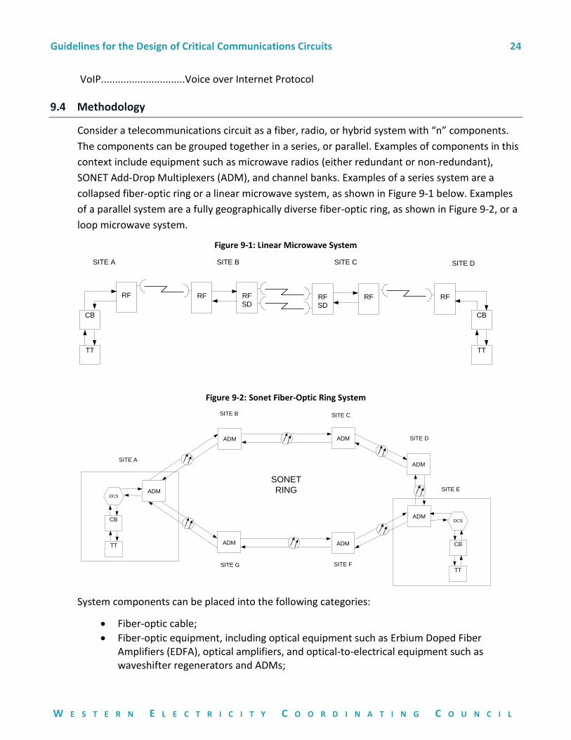
9.4 Methodology
Consider a telecommunications circuit as a fiber, radio, or hybrid system with “n” components.
The components can be grouped together in a series, or parallel. Examples of components in this
context include equipment such as microwave radios (either redundant or non-redundant),
SONET Add-Drop Multiplexers (ADM), and channel banks. Examples of a series system are a
collapsed fiber-optic ring or a linear microwave system, as shown in Figure 9-1 below. Examples
of a parallel system are a fully geographically diverse fiber-optic ring, as shown in Figure 9-2, or a
loop microwave system.
Figure 9-1: Linear Microwave System
RF RF
SDRF
SD
RF RF
SITE A SITE B SITE C
RF
SITE D
TT
CB
TT
CB
Figure 9-2: Sonet Fiber-Optic Ring System
ADM
ADM
ADM
SITE AADM
ADMADM
SONET
RING
ADM
SITE B SITE C
SITE F
SITE E
SITE G
DCS
CB
TT
DCS
CB
TT
SITE D
System components can be placed into the following categories:
Fiber-optic cable;
Fiber-optic equipment, including optical equipment such as Erbium Doped Fiber Amplifiers (EDFA), optical amplifiers, and optical-to-electrical equipment such as waveshifter regenerators and ADMs;

Guidelines for the Design of Critical Communications Circuits 25
W E S T E R N E L E C T R I C I T Y C O O R D I N A T I N G C O U N C I L
Radio paths, including Rayleigh and blackout (storm) fading;
Radio equipment, including Radio Frequency (RF) components, modems, and higher-order, multiplex sub-assemblies;
Other equipment, including digital cross-connect systems, channel banks, site power, and end equipment such as TT (relays are not included).
Modeling end-to-end circuit availability involves drawing components and subsystems that the
critical circuit uses. A subsystem can be a SONET ring (which is a group of parallel components)
or a linear microwave network (which is a group of series components). A circuit may be routed
over multiple subsystems; for example, multiple SONET rings (see Figure 9-3). Interface
equipment used by the circuit to provide entrance or exit from the telecommunications
subsystems, or for interconnecting between subsystems (such as DCSs), must also be included
in the availability calculations.
Figure 9-3: Multi-Ring System
SITE D
ADM
DCSADM
ADM
SITE JADM
ADM ADM
SONET
RING
#2
CB
TT
ADM
SITE ISITE H
SITE L
SITE M
SITE K
ADM
DCSADM
ADM
SITE AADM
ADMADM
SONET
RING
#1
CB
TT
ADM
SITE B SITE C
SITE F
SITE E
SITE G
DCS
SITE D
Annual downtime can be calculated for each ring or subsystem and simply added to the
downtime attributed to the end equipment (such as TT) and the communications equipment
entering and exiting the rings (ring interface equipment). In the case of non-redundant TT over
a single communications circuit and single-homed rings, the availability calculations are
straightforward. Availability criteria and “no credible single point of failure” criteria may require
redundant end equipment and alternately routed circuits that, in turn, may result in dual-
homed rings or other parallel communications routes. In such cases, availability modeling
becomes more complex.
9.5 Availability Input Parameters
The model and methodology described herein uses Failures In Time (FIT), from which failure rate
() can be calculated, and Mean Time to Restore (MTR), from which restore rate () can be
calculated.
A FIT calculation is used to calculate the availability of a circuit. In the case of fiber,
the recommended FITs per mile is 342 (212.50 per km), which equates to 3 fiber-optic cable
failures per 1,000 route miles per year. A fiber-optic failure rate of 342 fiber-optic FITs per mile
(212.50 per km) is based on telecom industry studies on fiber-optic sheath failure rates 2/. The

Guidelines for the Design of Critical Communications Circuits 26
W E S T E R N E L E C T R I C I T Y C O O R D I N A T I N G C O U N C I L
recommended fiber-optic failure is again conservative, as not all fiber-optic sheath failures result
in service affecting outages (damage to lit fibers). Individual utilities can adjust the fiber-optic
failure rate based upon their experience. Within a FIT calculation, the telecom engineer must
obtain and input FIT numbers for all of the other system components listed in Section 9.4, except
for radio paths.
Microwave point-to-point radio annual outage (downtime) seconds have to be calculated using
an RF path engineering software analysis tool. The total RF outage results are directly added into
the availability model (in the case of a linear microwave subsystem) or indirectly factored into
the model (in the case of a hybrid, fiber-microwave ring). An example of a hybrid, fiber-
microwave ring system will be given later.
FIT numbers can be acquired from the various equipment manufacturers. Ideally, the overall FIT
number should reflect the exact application for a particular piece of equipment. For example,
when calculating the availability of a circuit, the FIT numbers for a pass-through ADM node will
be slightly less than the two ADMs that add/drop the circuit. However, for simplicity, if the two
FIT numbers are very close, the higher FIT number can be chosen for a particular make and
model. Manufacturers may furnish MTBF in lieu of FIT numbers for their equipment. MTBF
numbers can then be converted to FIT numbers using the conversion equation given in Section
9.2.
For parallel microwave radio equipment found in hot-standby, frequency, space, and quad (both
frequency and space with dual transmit antennas) diversity microwave systems; the
manufacturer should be able to provide an equivalent FIT number for the radio. The equivalent
FIT number can then be used in linear or hybrid models to calculate system availability (see
Examples 1 and 4 in Section 9.6 of this document). It should be expected that FIT numbers for
quad diversity microwave systems will be lower (due to more parallel components) than hot-
standby microwave systems.
Fiber-optic restoration MTRs are typically greater than communications equipment MTRs that
are based on the replacement of faulty cards. Therefore, these two different MTR values are
used in the model. An MTR of eight hours is typical for communications equipment inside a
control room. Individual utilities should define MTR based on the number of spares and access to
the sites in worst conditions. Fiber-optic MTR in the range of 12–24 hours is typical.
Circuit availability calculations are particularly sensitive to fiber-optic MTR. Fiber-optic MTR is a
very important parameter and should be based on the individual utility’s fiber-optic restoration
experiences and restoration programs in place. MTR includes incidents where interrupted service
(due to a severed cable) was restored by rolling service to working, spare dark fiber-optic strands
as well as a complete fiber-optic restoration. The use of temporary cable and temporary splices
can reduce restoration time in the case of complete cable failures.
Guidelines for the Design of Critical Communications Circuits 27
W E S T E R N E L E C T R I C I T Y C O O R D I N A T I N G C O U N C I L
Software and procedural downtime should be included in the availability calculations. The
contribution of software and procedural errors to the system downtime is subjective, but some
annual downtime should be allotted.
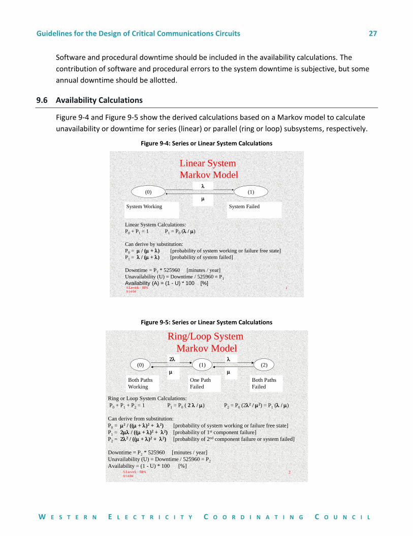
9.6 Availability Calculations
Figure 9-4 and Figure 9-5 show the derived calculations based on a Markov model to calculate
unavailability or downtime for series (linear) or parallel (ring or loop) subsystems, respectively.
Figure 9-4: Series or Linear System Calculations
S.Larvick – BPA
9/14/041
Linear System
Markov Model
Linear System Calculations:
P0 + P1 = 1 P1 = P0 ( / )
Can derive by substitution:
P0 = / ( + ) [probability of system working or failure free state]
P1 = / ( + ) [probability of system failed]
Downtime = P1 * 525960 [minutes / year]
Unavailability (U) = Downtime / 525960 = P1
Availability (A) = (1 - U) * 100 [%]
(0) (1)
System Working System Failed
Figure 9-5: Series or Linear System Calculations
S.Larvick – BPA
9/14/042
Ring/Loop System
Markov Model
(0) (1) (2)2
Both Paths
Working
One Path
Failed
Both Paths
Failed
Ring or Loop System Calculations:
P0 + P1 + P2 = 1 P1 = P0 ( 2 / ) P2 = P0 (22 / 2) = P1 ( / )
Can derive from substitution:
P0 = 2 / (( + )2 + 2) [probability of system working or failure free state]
P1 = 2 / (( + )2 + 2) [probability of 1st component failure]
P2 = 22 / (( + )2 + 2) [probability of 2nd component failure or system failed]
Downtime = P2 * 525960 [minutes / year]
Unavailability (U) = Downtime / 525960 = P2
Availability = (1 - U) * 100 [%]
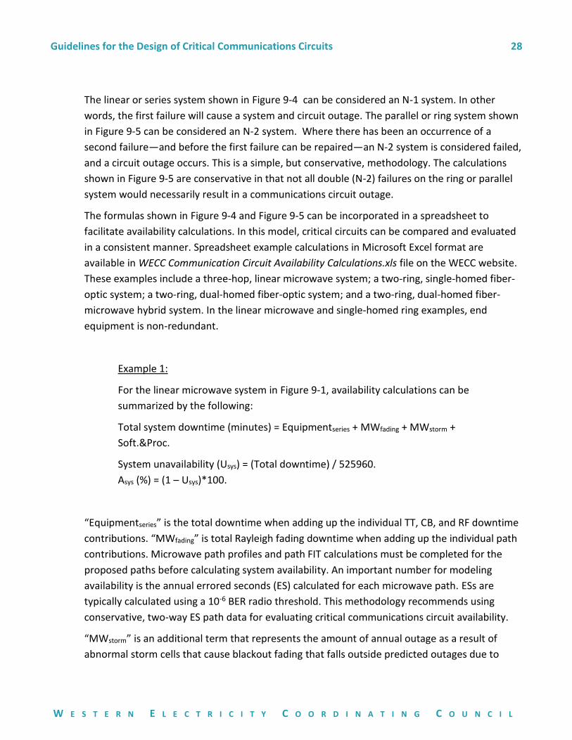
Guidelines for the Design of Critical Communications Circuits 28
W E S T E R N E L E C T R I C I T Y C O O R D I N A T I N G C O U N C I L
The linear or series system shown in Figure 9-4 can be considered an N-1 system. In other
words, the first failure will cause a system and circuit outage. The parallel or ring system shown
in Figure 9-5 can be considered an N-2 system. Where there has been an occurrence of a
second failure—and before the first failure can be repaired—an N-2 system is considered failed,
and a circuit outage occurs. This is a simple, but conservative, methodology. The calculations
shown in Figure 9-5 are conservative in that not all double (N-2) failures on the ring or parallel
system would necessarily result in a communications circuit outage.
The formulas shown in Figure 9-4 and Figure 9-5 can be incorporated in a spreadsheet to
facilitate availability calculations. In this model, critical circuits can be compared and evaluated
in a consistent manner. Spreadsheet example calculations in Microsoft Excel format are
available in WECC Communication Circuit Availability Calculations.xls file on the WECC website.
These examples include a three-hop, linear microwave system; a two-ring, single-homed fiber-
optic system; a two-ring, dual-homed fiber-optic system; and a two-ring, dual-homed fiber-
microwave hybrid system. In the linear microwave and single-homed ring examples, end
equipment is non-redundant.
Example 1:
For the linear microwave system in Figure 9-1, availability calculations can be
summarized by the following:
Total system downtime (minutes) = Equipmentseries + MWfading + MWstorm +
Soft.&Proc.
System unavailability (Usys) = (Total downtime) / 525960.
Asys (%) = (1 – Usys)*100.
“Equipmentseries” is the total downtime when adding up the individual TT, CB, and RF downtime
contributions. “MWfading” is total Rayleigh fading downtime when adding up the individual path
contributions. Microwave path profiles and path FIT calculations must be completed for the
proposed paths before calculating system availability. An important number for modeling
availability is the annual errored seconds (ES) calculated for each microwave path. ESs are
typically calculated using a 10-6 BER radio threshold. This methodology recommends using
conservative, two-way ES path data for evaluating critical communications circuit availability.
“MWstorm” is an additional term that represents the amount of annual outage as a result of
abnormal storm cells that cause blackout fading that falls outside predicted outages due to
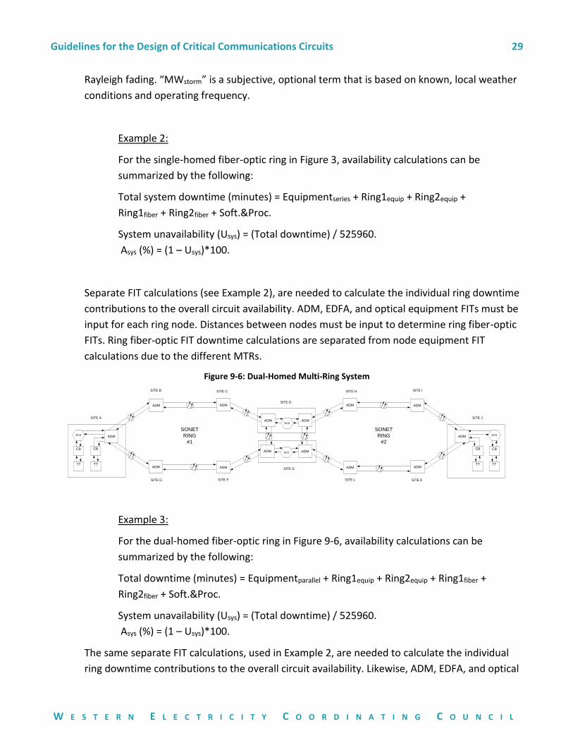
Guidelines for the Design of Critical Communications Circuits 29
W E S T E R N E L E C T R I C I T Y C O O R D I N A T I N G C O U N C I L
Rayleigh fading. “MWstorm” is a subjective, optional term that is based on known, local weather
conditions and operating frequency.
Example 2:
For the single-homed fiber-optic ring in Figure 3, availability calculations can be
summarized by the following:
Total system downtime (minutes) = Equipmentseries + Ring1equip + Ring2equip +
Ring1fiber + Ring2fiber + Soft.&Proc.
System unavailability (Usys) = (Total downtime) / 525960.
Asys (%) = (1 – Usys)*100.
Separate FIT calculations (see Example 2), are needed to calculate the individual ring downtime
contributions to the overall circuit availability. ADM, EDFA, and optical equipment FITs must be
input for each ring node. Distances between nodes must be input to determine ring fiber-optic
FITs. Ring fiber-optic FIT downtime calculations are separated from node equipment FIT
calculations due to the different MTRs.
Figure 9-6: Dual-Homed Multi-Ring System
SITE D
ADM
DCSADM
ADM
SITE JADM
ADM ADM
SONET
RING
#2
CB
TT
ADM
SITE ISITE H
SITE L SITE K
ADM
DCSADM
ADM
SITE AADM
ADMADM
SONET
RING
#1
CB
TT
ADM
SITE B SITE C
SITE F
SITE E
SITE G
SITE D
CB
TT
CB
TT
DCS
DCS
Example 3:
For the dual-homed fiber-optic ring in Figure 9-6, availability calculations can be
summarized by the following:
Total downtime (minutes) = Equipmentparallel + Ring1equip + Ring2equip + Ring1fiber +
Ring2fiber + Soft.&Proc.
System unavailability (Usys) = (Total downtime) / 525960.
Asys (%) = (1 – Usys)*100.
The same separate FIT calculations, used in Example 2, are needed to calculate the individual
ring downtime contributions to the overall circuit availability. Likewise, ADM, EDFA, and optical
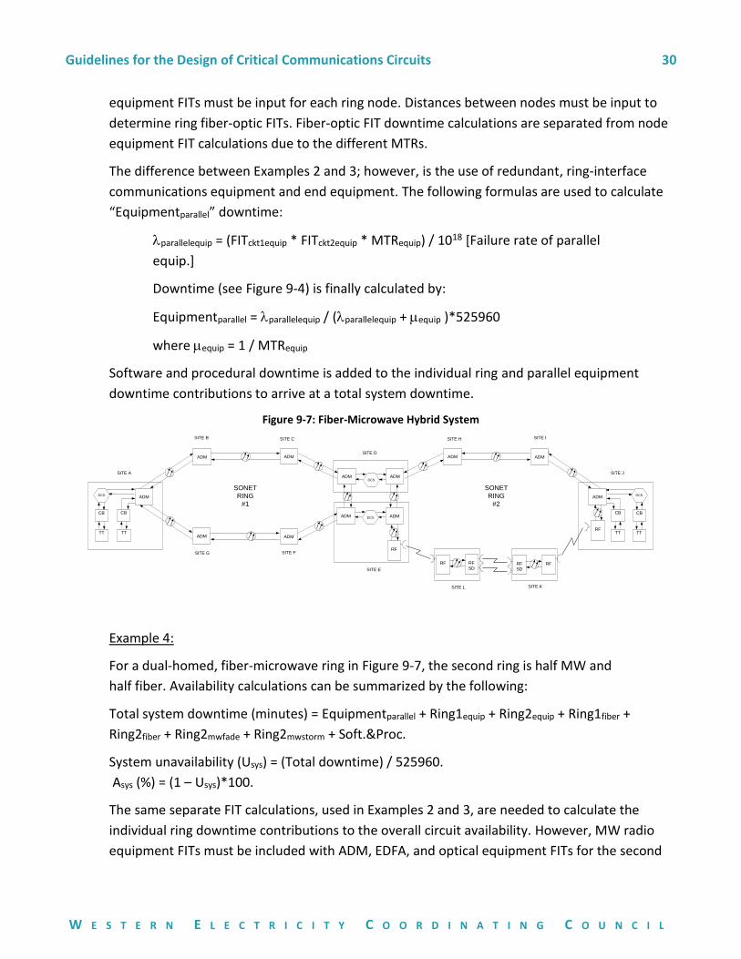
Guidelines for the Design of Critical Communications Circuits 30
W E S T E R N E L E C T R I C I T Y C O O R D I N A T I N G C O U N C I L
equipment FITs must be input for each ring node. Distances between nodes must be input to
determine ring fiber-optic FITs. Fiber-optic FIT downtime calculations are separated from node
equipment FIT calculations due to the different MTRs.
The difference between Examples 2 and 3; however, is the use of redundant, ring-interface
communications equipment and end equipment. The following formulas are used to calculate
“Equipmentparallel” downtime:
parallelequip = (FITckt1equip * FITckt2equip * MTRequip) / 1018 [Failure rate of parallel
equip.]
Downtime (see Figure 9-4) is finally calculated by:
Equipmentparallel = parallelequip / (parallelequip + equip )*525960
where equip = 1 / MTRequip
Software and procedural downtime is added to the individual ring and parallel equipment
downtime contributions to arrive at a total system downtime.
Figure 9-7: Fiber-Microwave Hybrid System
SITE D
ADM
DCSADM
ADM
SITE JADM
SONET
RING
#2
CB
TT
ADM
SITE ISITE H
SITE L SITE K
ADM
DCSADM
ADM
SITE AADM
ADMADM
SONET
RING
#1
CB
TT
ADM
SITE B SITE C
SITE F
SITE E
SITE G
SITE D
CB
TT
CB
TT
DCS
DCS
RF
RF
SDRF
SD
RF
RF
RF
Example 4:
For a dual-homed, fiber-microwave ring in Figure 9-7, the second ring is half MW and
half fiber. Availability calculations can be summarized by the following:
Total system downtime (minutes) = Equipmentparallel + Ring1equip + Ring2equip + Ring1fiber +
Ring2fiber + Ring2mwfade + Ring2mwstorm + Soft.&Proc.
System unavailability (Usys) = (Total downtime) / 525960.
Asys (%) = (1 – Usys)*100.
The same separate FIT calculations, used in Examples 2 and 3, are needed to calculate the
individual ring downtime contributions to the overall circuit availability. However, MW radio
equipment FITs must be included with ADM, EDFA, and optical equipment FITs for the second
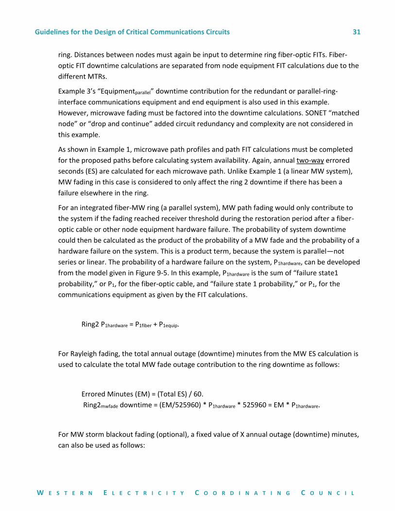
Guidelines for the Design of Critical Communications Circuits 31
W E S T E R N E L E C T R I C I T Y C O O R D I N A T I N G C O U N C I L
ring. Distances between nodes must again be input to determine ring fiber-optic FITs. Fiber-
optic FIT downtime calculations are separated from node equipment FIT calculations due to the
different MTRs.
Example 3’s “Equipmentparallel” downtime contribution for the redundant or parallel-ring-
interface communications equipment and end equipment is also used in this example.
However, microwave fading must be factored into the downtime calculations. SONET “matched
node” or “drop and continue” added circuit redundancy and complexity are not considered in
this example.
As shown in Example 1, microwave path profiles and path FIT calculations must be completed
for the proposed paths before calculating system availability. Again, annual two-way errored
seconds (ES) are calculated for each microwave path. Unlike Example 1 (a linear MW system),
MW fading in this case is considered to only affect the ring 2 downtime if there has been a
failure elsewhere in the ring.
For an integrated fiber-MW ring (a parallel system), MW path fading would only contribute to
the system if the fading reached receiver threshold during the restoration period after a fiber-
optic cable or other node equipment hardware failure. The probability of system downtime
could then be calculated as the product of the probability of a MW fade and the probability of a
hardware failure on the system. This is a product term, because the system is parallel—not
series or linear. The probability of a hardware failure on the system, P1hardware, can be developed
from the model given in Figure 9-5. In this example, P1hardware is the sum of “failure state1
probability,” or P1, for the fiber-optic cable, and “failure state 1 probability,” or P1, for the
communications equipment as given by the FIT calculations.
Ring2 P1hardware = P1fiber + P1equip.
For Rayleigh fading, the total annual outage (downtime) minutes from the MW ES calculation is
used to calculate the total MW fade outage contribution to the ring downtime as follows:
Errored Minutes (EM) = (Total ES) / 60.
Ring2mwfade downtime = (EM/525960) * P1hardware * 525960 = EM * P1hardware.
For MW storm blackout fading (optional), a fixed value of X annual outage (downtime) minutes,
can also be used as follows:
Guidelines for the Design of Critical Communications Circuits 32
W E S T E R N E L E C T R I C I T Y C O O R D I N A T I N G C O U N C I L
Ring2mwstorm downtime = (X/525960) * P1hardware * 525960 = X * P1hardware.
Software and procedural downtime is added to the ring and parallel equipment downtime
contributions to arrive at a total system downtime.
9.7 References
1/ WECC Communications System Performance Guide for Electric Protection Systems
2/ The History, Prevention, and Impact of Fiber Optic Cable Failures, Samuel V. Lisle, Bellcore, June
1993.
3/ Reliability Evaluation of Engineering Systems, 2nd Edition, Roy Billinton and Ronald N. Allan,
Plenum Press, 1992.
Approved by:
Approving Committee, Entity, or Person Date
WECC Technical Operations Subcommittee February 7, 2017
WECC Operating Committee