Embed Size (px)
Citation preview

GUIDELINES FOR SEPTIC SYSTEM DESIGN
Single Family ResidentialFor multifamily or commercial buildings,
Or
If in the Oakdale area, contact theDepartment of Environmental Resources
Regarding septic system design.
NOTE: A building permit is required for all new homes septic system
installations. BUILDINGPERMITS: Stanislaus County Department of Building Inspection, 1010 10TH
Street, 3rd Floor Suite 3400, Modesto, CA (209) 5256330 REPAIRPERMITS: Stanislaus County Division of Environmental Health, 3800 Cornucopia
Way, Suite C, Modesto, CA 7:30 a.m. to 5:00 p.m. INSPECTION: Stanislaus County Division of Environmental Health, 3800 Cornucopia
Way, Suite C, Modesto, CA 7:30 8:30 a.m. or 4:00 5:00 p.m. SPECIALNOTE: For aerobic treatment tank users, the installation guidelines are
basically the same as for septic tank systems. Contact the Divisionof Environmental Health regarding sizing and operationalrequirements specific to aerobic treatment systems. A list ofapproved aerobic treatment units is available from our office.
INSTALLATION REQUIREMENTSAll household sewage or other liquid waste shall be disposed of through an approvedsewage disposal system. Sewage disposal systems designed for individual dwellingsshall consist of a sewer line from the house to the treatment tank, the tank,distribution boxes, leach lines and/or seepage pits.

A. HOUSE TO TREATMENT TANK CONNECTION
1. Purpose: Carry sewage from the building to the treatment tank. 2. Cleanout: To be provided if more than one 45 degree angle is made. 3. Material: Approved pipe, per Uniform Plumbing Code. 4. Stubout: Should be installed so as to prevent the initial portion of the leach line rock surface from being greater than 24 inches below grade.
Multiple story dwellings require special foundation passages. (Figure 1) 5. Building sewer: Should not be less than ¼” fall per linear foot.
B. SEPTIC TANK (AEROBIC TANKS ALSO)
1. Purpose: The septic tank retains raw sewage and separates the solid fromthe liquids by sedimentation and liquification through bacterial action,which permits a relatively clear liquid effluent to flow into leach linesand/or seepage pits. (Figure 2)
2. Materials:
a. Approved, precast concrete.b. Approved, poured in place concrete.c. Approved, fiberglass, polyethylene, etc. (IAPMO cert.)
3. Location: The septic tank must be a minimum of five feet (5') from any
foundation, structure, patio, etc.; fifty feet (50') from any private well andone hundred feet (100') from any public well.
C. DISTRIBUTION BOX
1. Purpose: The distribution box distributes the liquid from the septic tankequally among two or more leach lines and/or seepage pits. Thedistribution box also provides an inspection point and may be used whennecessary drain field additions are made. When a seepage pit is installedat the end of a leach line, a 5 foot section of nonperforated pipe can beused without the use of a distribution box, to make this connection.
2. Specifications:
a. Minimum size 12" square OR 12" in diameter.b. Constructed of concrete in a monolithic pour or other materials
approved by the Director or Environmental Health.c. Minimum depth 12".d. Inlet pipe to be a minimum of 2" higher than outlets.e. Footing all “D” boxes must be set on a natural or compacted soil.f. A 5' nonperforated pipe to be installed between septic tankand distribution box.
g. The pipes to be sealed with mortar or plastic seals to prevent leakage

from around the pipe. D. LEACH LINES
1. Purpose: Leach lines dispose of liquid waste from the septic tank throughpercolation into the soil and evapotranspiration into the air or up take byvegetation through the root system.
2. Materials: Approved 3" or 4" perforated pipe, washed drain rock (¾” 2
½”), untreated building paper or straw. *Graveless leach field chambersmaybe substituted for gravel and perforated pipe. Sizing of requiredsurface area based upon a 0.70 multiplier.
3. Location*: Leach lines must be a minimum of fifty feet (50') from a
private well, one hundred feet (100') from any public well, five feet (5')from any property line, eight feet (8') from any building, structure, patio,etc., 12 feet from leach line or seepage pit (center to center), and five feet(5') from any domestic water lines.
4. Design: The trench shall be 18 36 inches wide and must be a minimum
of 30" deep. The perforated pipe must be laid level on top of a minimumof 12" of gravel, to within 1' of the end of the trench unless an end cap isused. Rock is added around and 2 inches over the pipe to standard depth,then covered with untreated building paper or straw. The standard depthof rock is 18" total, credit for greater depths must have prior approvalfrom this department. (Figure 3 & Figure 3a)
NOTE: Leaching area is determined from area, in square feet of trench
bottom. Therefore, a trench 3 feet wide by 10 feet long wouldyield 30 square feet of leaching area. (Figure 3a)
A. The maximum credited width of a leach line is three (3) feetB. Leach lines will not be credited for any gravel deeper than three (3)
feet under the perforated drain line. Maximum drain line credit willbe seven (7) square feet per running foot.
C. Leach line trench layout in sloping ground. (Figure 3b)
* All measurements are from the edge of the trench unless otherwise noted. E. SEEPAGE PIT
1. Purpose: Seepage pits are used to dispose of liquid waste effluent from theseptic tank through percolation and evapotranspiration. Pits are generally

used when soil conditions limit the exclusive use of leach lines. There mustbe a minimum of 10' of unsaturated soil between the bottom of the pit andgroundwater. SEEPAGE PITS MUST NOT EXCEED 50% OF THE ORIGINALSYSTEM WITHOUT PRIOR APPROVAL.
2. Materials: Approved perforated pipe, washed drain rock (2/4" to 2½”)
untreated building paper or straw. (Figure 4) 3. Location: Seepage pits must be a minimum of one hundred (100') from a
private well, eight (8') from any property line or building, structure, etc.,and five (5') from domestic water lines.
4. Design: Seepage pits are three (3') wide with varying lengths and depths.
The perforated pipe is laid level over the gravel and extends to within onefoot (1') of the end of the excavation. Rock is added on top of the pipe toa minimum of two (2") in depth, then covered with untreated buildingpaper or straw. (Figure 4)
Need trench depth for definition (8’ trench depth).
NOTE: Leaching area of a pit is determined from the amount of rock thatis used in yards. Therefore, a pit 3' wide, 20' long with 9' of gravel underthe pipe would contain 20 cubic yards of rock, equaling 200 square feet ofleaching area. This is a credit of 10 square feet per cubic yard of gravel.
IMPORTANT! The designated replacement or future drain field expansion area shallbe adequate to install at least 100% replacement should the original system fail. Nodivision of the lot or erection of structures shall be made if such action impairs theusefulness of the designated expansion area. F. PIPE SPECIFICATIONS
1. Solid Pipe For sewage disposal systems, pipes shall conform to thestandards of the most recent edition of the Uniform Plumbing Code publishedby IAPMO. Materials approved are acrylonitrilebutadienestyrene (ABS) andpolyvinyl chloride (PVC) plastic pipe. Pipe diameter shall be three or fourinches.
2. Distribution Pipe Perforated pipe for distribution system shall conform to themost recent edition of the Uniform Plumbing Code published by IAPMO. Pipediameter shall be three or four inches.
LOCATION OF SEWAGE DISPOSAL SYSTEMSMinimum Distance To Septic Tank Leach Line Seepage Pit
Building or Structure 5' 8' 8'Property Line 5' 5' 8'
Private Well 50' 50' 100'Public Well 100' 100' 150'Streams / River 100' 100' 200'Lake or Reservoir 50' 200' 200'Seepage Pit 5' 12'(CENTER) 12'(CENTER)Leach Line 5' 12'(CENTER) 12'(CENTER)Water Line 5' 5' 5'Distribution Box 5' 5' 5'Dry Well (Storm Drain) 8' 50' 50'French Drain 8' 12' 12'Drainage Course/Unlined Irrigation Ditch 25' 50' 50'Storm Drainage Ponds 25' 50' 50'Cut, Bank, or Fill 10' 4h* 4h*
*h = vertical height of cut/bank, measured from top of the bank with 100'maximum unless greater distance is deemed necessary by the Department.
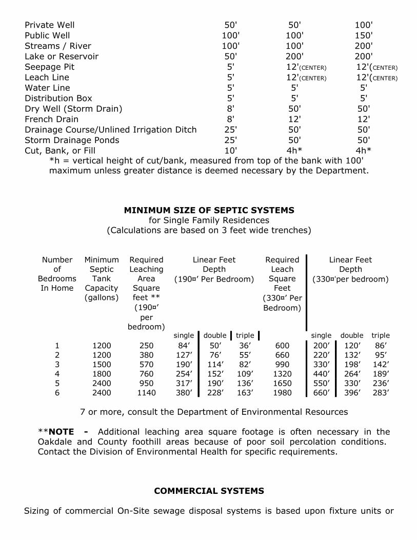
MINIMUM SIZE OF SEPTIC SYSTEMSfor Single Family Residences
(Calculations are based on 3 feet wide trenches)
Numberof
BedroomsIn Home
MinimumSepticTank
Capacity(gallons)
RequiredLeachingAreaSquarefeet **(190¤’per
bedroom)
Linear FeetDepth
(190¤’ Per Bedroom)
RequiredLeachSquareFeet
(330¤’ PerBedroom)
Linear FeetDepth
(330¤’per bedroom)
single double triple single double triple1 1200 250 84’ 50’ 36’ 600 200’ 120’ 86’2 1200 380 127’ 76’ 55’ 660 220’ 132’ 95’3 1500 570 190’ 114’ 82’ 990 330’ 198’ 142’4 1800 760 254’ 152’ 109’ 1320 440’ 264’ 189’5 2400 950 317’ 190’ 136’ 1650 550’ 330’ 236’6 2400 1140 380’ 228’ 163’ 1980 660’ 396’ 283’
7 or more, consult the Department of Environmental Resources
**NOTE Additional leaching area square footage is often necessary in theOakdale and County foothill areas because of poor soil percolation conditions. Contact the Division of Environmental Health for specific requirements.
COMMERCIAL SYSTEMS Sizing of commercial OnSite sewage disposal systems is based upon fixture units or

estimated waste discharge volume as per the Uniform Plumbing Code, Table 73 andK2. In most situations, commercial systems must use AEROBIC TREATMENT UNITSinstead of septic tanks.
EXAMPLE OF ONSITE SEWAGE DISPOSAL CALCULATIONS FOR A
COMMERCIAL PROJECT. Office and warehouse proposed, approximately 10 employees present.
Plumbing fixtures No. Fixture unit* Total Unitswater closets 3X 6 18hand sinks 3X 1 3janitor’s sinks 1X 3 3*UPC, Table 41 24
A. Sizing the tank
From the projected liquid waste to be generated, a 1200 gallon septic tank or a500 gpd aerobic treatment unit required. Measure X compliant.
B. Expected wastewater generation
From UPC, Table K3 (See Exhibit A): Office and warehouse = 20gallon/day/employee.Total square footage = 4200 square feet
office space = 100 x 1/100** = 10 employeeswarehouse space = 3200 x 1/500** = 6 employees
Total 16 employees16 employees x 20 g/d = 320 gpd**Uniform Building Code (UBC), Table 33A (occupant load/sq. ft.)
C. Sizing disposal field options
Based on Soil Description: Sandy LoamApplication rate from UPC, Table K4:Maximum absorption capacity = 2.5 gal/sq.ft./dayDisposal field size 320 gpd = 128 sq.ft. Use 45' of 3' wide trench.
2.5
Note: A soils specialist or civil engineer has to verify the area’s soil type and signthe design specification sheet.
Based upon Percolation rate = at 1 inch in 10 minutesApplication rate from the Manual of Septic Tank Practice:
rate = 1.6 gal./sq.ft./dayField size 320 gpd = 225 sq.ft. Use 75' of 3' wide trench
1.6Note: The percolation test must be performed by soils specialists or civil
engineers.
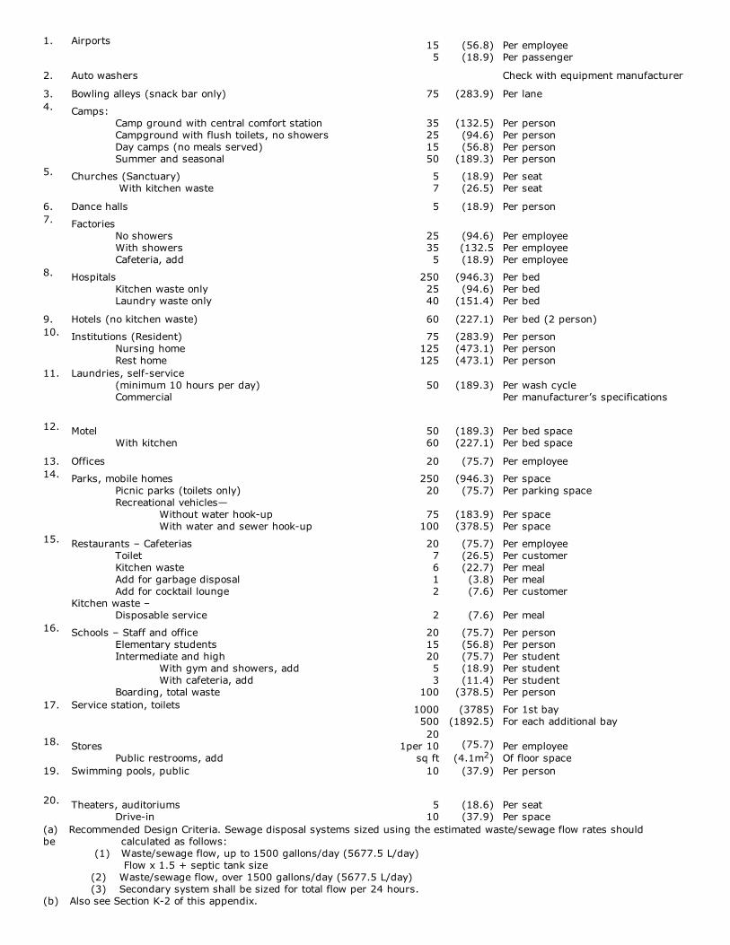
EXHIBIT A Estimated Waste/Sewage Flow Rates TABLE K3Because of the many variables encountered, it is not possible to set absolute vales for waste/sewage flow rate for all situations. The designer should evaluate eachsituation and, if figures in this table need modification, they should be made with the concurrence of the Administrative Authority.
TYPE OF OCCUPANCY GALLONS (LITERS) PER DAY
1.
Airports
155
(56.8)(18.9)
Per employeePer passenger
2. Auto washers Check with equipment manufacturer
3. Bowling alleys (snack bar only) 75 (283.9) Per lane4.
Camps:Camp ground with central comfort stationCampground with flush toilets, no showersDay camps (no meals served)Summer and seasonal
35251550
(132.5)(94.6)(56.8)(189.3)
Per personPer personPer personPer person
5.
Churches (Sanctuary) With kitchen waste
57
(18.9)(26.5)
Per seatPer seat
6. Dance halls 5 (18.9) Per person7.
FactoriesNo showersWith showersCafeteria, add
25355
(94.6)(132.5(18.9)
Per employeePer employeePer employee
8.
HospitalsKitchen waste onlyLaundry waste only
2502540
(946.3)(94.6)(151.4)
Per bedPer bedPer bed
9. Hotels (no kitchen waste) 60 (227.1) Per bed (2 person)10.
Institutions (Resident)Nursing homeRest home
75125125
(283.9)(473.1)(473.1)
Per personPer personPer person
11.
Laundries, selfservice(minimum 10 hours per day)Commercial
50
(189.3)
Per wash cyclePer manufacturer’s specifications
12.
MotelWith kitchen
5060
(189.3)(227.1)
Per bed spacePer bed space
13. Offices 20 (75.7) Per employee14.
Parks, mobile homesPicnic parks (toilets only)Recreational vehicles—
Without water hookupWith water and sewer hookup
25020
75100
(946.3)(75.7)
(183.9)(378.5)
Per spacePer parking space Per spacePer space
15.
Restaurants – CafeteriasToiletKitchen wasteAdd for garbage disposalAdd for cocktail lounge
Kitchen waste –Disposable service
207612 2
(75.7)(26.5)(22.7)(3.8)(7.6)
(7.6)
Per employeePer customerPer mealPer mealPer customer Per meal
16.
Schools – Staff and officeElementary studentsIntermediate and high
With gym and showers, addWith cafeteria, add
Boarding, total waste
20152053
100
(75.7)(56.8)(75.7)(18.9)(11.4)(378.5)
Per personPer personPer studentPer studentPer studentPer person
17.
Service station, toilets
1000500
(3785)(1892.5)
For 1st bayFor each additional bay
18.
StoresPublic restrooms, add
201per 10
sq ft(75.7)
(4.1m2)Per employeeOf floor space
19.
Swimming pools, public
10
(37.9) Per person
20.
Theaters, auditoriumsDrivein
510
(18.6)(37.9)
Per seatPer space
(a) Recommended Design Criteria. Sewage disposal systems sized using the estimated waste/sewage flow rates shouldbe calculated as follows: (1) Waste/sewage flow, up to 1500 gallons/day (5677.5 L/day) Flow x 1.5 + septic tank size
(2) Waste/sewage flow, over 1500 gallons/day (5677.5 L/day)(3) Secondary system shall be sized for total flow per 24 hours.
(b) Also see Section K2 of this appendix.
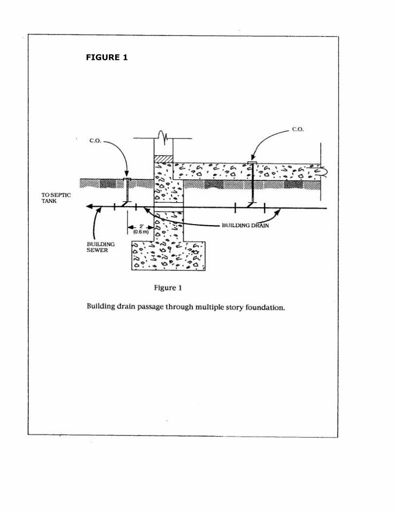
FIGURE 1


FIGURE 3
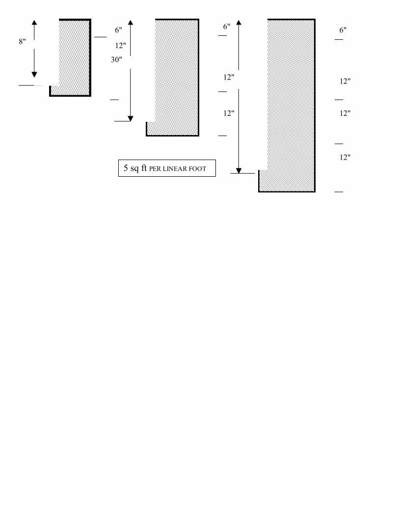
5 sq ft PER LINEAR FOOT
18"
30"
42"
6"
12"
6"
12"
12"
6"
12"
12"
12"

FIGURE3 – A
TYPICALLEACHLINE
3 sq ftPERLINEARFOOT
36"
7 sq ftPERLINEARFOOT
36"
36"
FIGURE 3B

FIGURE 4

TYPICAL SEEPAGE PIT


![St. STANISLAUS MAGAZINEst-stanislaus-gy.com/Magazines/1971/1971-CollegeSection.pdfSt. STANISLAUS MAGAZINE VOL. [29] ... Gavin Hinds and Trevor Gibbs having the general edge over the](https://img.pdfslide.us/doc/110x75/5aa5a1287f8b9a7c1a8da81e/st-stanislaus-magazinest-stanislaus-gycommagazines19711971-stanislaus-magazine.jpg)