Embed Size (px)
Citation preview

Developed as part of WRC K5/2957//4:
Knowledge exchange to improve implementation of irrigation water
measurement/metering at farming and scheme level
2019
Guidelines for selecting measuring devices for
irrigation water measurement:
Open channel flow

PAGE 1
INTRODUCTION
Dear Water User
Good measurement and monitoring of water use assist with efficient irrigation planning and management at both scheme and farm
level.
To this effect, the Department of Water and Sanitation has published several regulations in terms of section 26 (1) (b) of the
National Water Act (no. 36 of 1998) requiring that the use of water from a water resource be monitored, measured and recorded:
• Government Notice 538 of 2016 – Revision of General Authorisation for the taking and storing of water
• Government Notice 131 of 2017 – Regulation requiring that the taking of water for irrigation purposes be measured,
recorded and reported.
• Government Notice 141 of 2018 – Regulation instructing Irrigation Boards and Water User Associations to install water
measuring devices for water taken for irrigation purposes and to monitor compliance to regulations requiring that the
taking of water for irrigation purposes be measured, recorded and reported.
This booklet serves as a brief guide to different types of water meters and how they operate. The layout of the booklet entails a brief
description of how each of the metering devices work, how it should be installed, the costs involved, its accuracy, the maintenance
required, their advantages and disadvantages and contact details of various suppliers.
We trust that you will find the information useful.
Sarlet Barnard
TABLE OF CONTENTS
INTRODUCTION ...................................................................................................................................................................................... 1
TABLE OF CONTENTS .............................................................................................................................................................................. 1
CRITICAL FUNCTIONS AND IMPORTANT CONSIDERATIONS .................................................................................................................. 2
GENERAL INSTALLATION REQUIREMENTS FOR MEASURING DEVICES .................................................................................................. 2
WEIRS ..................................................................................................................................................................................................... 3
FLUMES .................................................................................................................................................................................................. 4
ORIFICES ................................................................................................................................................................................................. 5
MECHANICAL VELOCITY / CURRENT METER .......................................................................................................................................... 6
ACOUSTIC DOPPLER VELOCITY METER .................................................................................................................................................. 7
ACOUSTIC DOPPLER DISCHARGE MEASUREMENT ................................................................................................................................. 8
ACOUSTIC TRANSIT TIME DISCHARGE MEASUREMENT ......................................................................................................................... 9
TABLE 1: SUMMARY OF MEASUREMENT DEVICES FOR OPEN CHANNEL FLOW .................................................................................. 10
PAGE 2
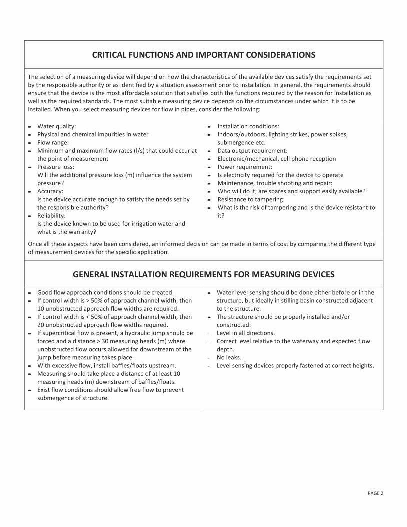
CRITICAL FUNCTIONS AND IMPORTANT CONSIDERATIONS
The selection of a measuring device will depend on how the characteristics of the available devices satisfy the requirements set by the responsible authority or as identified by a situation assessment prior to installation. In general, the requirements should ensure that the device is the most affordable solution that satisfies both the functions required by the reason for installation as well as the required standards. The most suitable measuring device depends on the circumstances under which it is to be installed. When you select measuring devices for flow in pipes, consider the following:
Water quality: Physical and chemical impurities in water Flow range: Minimum and maximum flow rates (l/s) that could occur at
the point of measurement Pressure loss:
Will the additional pressure loss (m) influence the system pressure?
Accuracy: Is the device accurate enough to satisfy the needs set by the responsible authority?
Reliability: Is the device known to be used for irrigation water and what is the warranty?
Installation conditions: Indoors/outdoors, lighting strikes, power spikes,
submergence etc. Data output requirement: Electronic/mechanical, cell phone reception Power requirement: Is electricity required for the device to operate Maintenance, trouble shooting and repair: Who will do it; are spares and support easily available? Resistance to tampering: What is the risk of tampering and is the device resistant to
it?
Once all these aspects have been considered, an informed decision can be made in terms of cost by comparing the different type of measurement devices for the specific application.
GENERAL INSTALLATION REQUIREMENTS FOR MEASURING DEVICES
Good flow approach conditions should be created. If control width is > 50% of approach channel width, then
10 unobstructed approach flow widths are required. If control width is < 50% of approach channel width, then
20 unobstructed approach flow widths required. If supercritical flow is present, a hydraulic jump should be
forced and a distance > 30 measuring heads (m) where unobstructed flow occurs allowed for downstream of the jump before measuring takes place.
With excessive flow, install baffles/floats upstream. Measuring should take place a distance of at least 10
measuring heads (m) downstream of baffles/floats. Exist flow conditions should allow free flow to prevent
submergence of structure.
Water level sensing should be done either before or in the structure, but ideally in stilling basin constructed adjacent to the structure.
The structure should be properly installed and/or constructed:
- Level in all directions. - Correct level relative to the waterway and expected flow
depth. - No leaks. - Level sensing devices properly fastened at correct heights.

PAGE 3
WEIRS
HOW IT WORKS A weir is a low dam or overflow structure built across an open channel. It has a specific size and shape with a unique free-flow, head-discharge relationship. The edge or surface over which the water flows is called the crest. Discharge rates are determined by measuring the vertical distance from the crest to the water surface upstream from the crest. Weirs can be used for both high flows with the discharge measured using the water level upstream of the weir or for volumetric flows in extremely low flow conditions that are too small to measure with a current meter. The sharp-crested weirs are most commonly used in smaller irrigation channels and are ideal for water distribution purposes. The V-notch is preferred in cases when very small discharges are measured because of the small cross-sectional area that leads to a greater variation in head.
Rectangular with end contractions
𝑄 = 1,84(𝐿 − 0,2ℎ)ℎ1,5
Rectangular without end contractions
𝑄 = 1,84𝐿ℎ1,5
V-notch
𝑄 = 1,38ℎ2,5
Trapezoidal/Cipoletti
𝑄 = 1,86𝐿ℎ1,5
INSTALLATION
Poor flow conditions just upstream of measuring structures can cause large errors in the flow measurement. The approaching flow upstream of the measuring structure should be sub-critical without any waves preventing large errors in flow measurement. The approaching channel should be straight for a recommended length of 40 times the hydraulic radius. Common installation requirements to all types of sharp crested weirs include:
- The upstream face must be vertical and the crest plates, usually of brass or stainless steel,
- must be provided with an accurately finished upstream square edge.
- The crest width must not exceed 3 mm and it must have a bevel on the downstream side.
- The measuring plate must be built perpendicular to the flow.
Adherence to these requirements will ensure the accuracy of the measuring structures.
COST ACCURACY MAINTENANCE
Not very expensive Accurate The approach to the weir crest must be kept free of sediments and deposits.
ADVANTAGES DISADVANTAGES
Easy to install. Handles a range of different flows. The V-notch is very sensitive at low flow
conditions.
Large structures are vulnerable to handle debris-laden flood discharges. The crest can become gradually rounded which effects the calibration. Sediment deposition occurs upstream of the weir in sediment laden
streams.

PAGE 4
FLUMES
HOW IT WORKS
A transition is created with a narrow section (throat) and a drop in the channel bottom to cause the flow to pass through critical depth in the flume’s throat. At the critical depth, energy is minimized and there is a direct relationship between water depth, velocity and flow rate. The flume may be operated as a free-flow, single-head measuring device, or operated under submerged-flow conditions where two heads are measured.
INSTALLATION
Position it near the diversion point and regulating gates. Position in a channel reach where an accurate head can
be measured. Do not install in poor flow conditions i.e. turbulent flow,
surging or unbalanced flow, or a poorly distributed velocity pattern.
Fully developed flow in long straight channels with mild slopes, free of curves, projections, and waves is required.
40 times the hydraulic radius of straight, unobstructed approach channel is required.
If control width > 50% of the approach channel, then 10 control widths of straight unobstructed approach required.
If control width < 50% of the approach channel, then 20 control widths of straight unobstructed approach are required.
If upstream flow exceeds critical velocity, a jump should be forced to occur. In this case, 30 measuring heads of straight unobstructed approach after the jump is should be provided.
If baffles are used to correct and smooth approach flow, then 10 measuring heads should be placed between the baffles and the measuring station.
COST ACCURACY MAINTENANCE
Under similar hydraulic and other boundary conditions, long-throated flumes are usually the most economical of all structures for accurately measuring flow.
2 to 3% under free-flow conditions.
Depends on location. Short flumes are accurate if the
standard dimensions are attained
The measuring plate should be zeroed with the crest of the flume on a regular basis.
Seal any cracks that might appear over time. Prevent movement in any part of the structure due
to earth movements to prevent inaccurate measurements.
The Parshall flumes should be constructed according to the structural dimensions.
ADVANTAGES DISADVANTAGES
Long-throated flumes can have different cross-sectional shapes. Can be custom fitted into most canal-site geometries
Can measure a range of discharges and can be made into portable devices. Have few problems with floating debris and sediment. A post construction rating table can be produced. Computer techniques can be used to design, calibrate and
analytically rate long-throated flumes.
The short-throated flumes need to be laboratory-calibrated, due to curvilinear flow.
The position of the measuring plate can easily be tampered with to give readings lower than the actual head.

PAGE 5
ORIFICES
HOW IT WORKS
An orifice is a sharp-edged opening in a vertical structure through which flow occurs. Orifices are commonly used on irrigation schemes for water distribution in open channel networks. Any submerged opening can be used as an orifice with the two popular types being: - Pipes (standard sizes) which is used to measure water deliveries for household and livestock water use. - Rectangular or circular pressure regulated sluice off-takes. Orifices can be operated under free flow or submerged conditions in which case two head (water depth) measurements are needed to calculate the flow using the standard orifice equation.
𝑄 = 𝐶𝐴√2𝑔ℎ
INSTALLATION
The installation normally consists of a two-well system which is connected with a standard pipe size to limit the abstraction rate. Standard designs also exist for pressure regulating sluice off-takes which might be unique for each irrigation scheme. This type of off-take is installed with a long weir in the main channel which is used to keep the head (water depth) behind the sluice gate relatively constant for a varying flow rate. Pressure regulating sluices are normally designed with fixed opening settings that deliver a constant flow rate. The flow rate multiplied by the time period gives the volume delivered through the off-take. An off-take should not be installed at the inside of a channel bend as this might lead to blockages.
COST ACCURACY MAINTENANCE
Not very expensive Fairly accurate. Remove any built up of sediment from time to time to prevent any blockages.
Inspect pressure regulating sluices for any tampering on a regular basis.
ADVANTAGES DISADVANTAGES
This type of off-take is a simple, practical and a robust method for water delivery measurements. The accuracy is good enough for water billing and channel operation purposes.
Standard designs for household and livestock pipe installations exist which will limit the maximum abstraction rate as well as any tampering.
Long weirs tend to fill up with sediment over time which might block the orifice opening.
Pressure regulating sluices are not tamper proof and various
methods have been used to increase the flow rate through it
illegally.

PAGE 6
MECHANICAL VELOCITY / CURRENT METER
HOW IT WORKS
The current meter is used to measure the water velocity which can be converted to a discharge for a known cross-section and water depth. Current meters are rated by dragging them through tanks of still water at known speeds. A typical measuring range is from 0.025 to 10 m/s. Although propellers are designed to pass weeds, algae and other debris, only a limited amount of foreign material can be tolerated in the flow. Even moderate amounts of algae or weeds can influence a propeller unless it is protected by screens.
INSTALLATION
The current meter is a portable device that needs no installation. Care should however be taken in the determination of the average velocity and the depths at which the different velocities should be measured.
COST ACCURACY MAINTENANCE
Expensive Accurate. The reliability and accuracy of measurement
with these meters are easily assessed by checking mechanical parts for damage and using spin-time tests for excess change of bearing friction.
Current meters are sensitive instruments and care must be taken during transportation to prevent accidental damage to the meter.
The meter should be carefully cleaned and properly lubricated after use.
ADVANTAGES DISADVANTAGES
Accurate. Easy to operate. Can be used in polluted water.
The current meter is a sensitive instrument and must be kept clean and properly lubricated at all times.
Good approach conditions are essential at the location
of use to ensure representative measurements.

PAGE 7
ACOUSTIC DOPPLER VELOCITY METER
HOW IT WORKS
The acoustic Doppler velocity meter (ADVM) is a proven, accurate solution for high-precision velocity measurements in channels and rivers. ADV meter performance has been shown to compare favorably with laser Doppler systems costing ten times as much. In addition, the ADVM is extremely simple to set up and use. Most users take high quality data within minutes of receiving the system. Many ADV meters have built in data loggers with an option to use telemetry.
INSTALLATION
The installation of this type of measuring device is normally easy. It can either be a fixed installation or a hand held device on a wading rod.
COST ACCURACY MAINTENANCE
Relatively expensive compared to other types of velocity meters.
- Almost no maintenance is needed other than ensuring a constant and reliable power supply.
ADVANTAGES DISADVANTAGES
Easy to install setup and maintain. Never needs calibration. Measures from 0.001 m/s up to 5 m/s. Easily attaches to wading rods. No moving parts. Velocity accuracy is not affected by biological growth.
Relatively expensive compared to other types of velocity
meters.
WEBSITES: https://www.campbellsci.co.za/
http://www.sontek.com

PAGE 8
ACOUSTIC DOPPLER DISCHARGE MEASUREMENT
HOW IT WORKS
Ultrasonic sensors use acoustic pulses to sense water levels and velocities. The Doppler type sensor is mounted below the water surface and transmits acoustic pulses that are reflected to the sensor by the water surface. The time interval between signal transmission and receipt, and the speed of sound in water, are used to compute the distance from the sensor to the water surface. This data is combined with the flow depth and the cross-sectional area at the measuring location to calculate the discharge.
Built-in water level sensor
External water meter sensor
INSTALLATION
The sensor should be in a place where silt or deposits are least likely to occur, but the stable approach conditions are preferred so that the flow should be evenly distributed across the channel and relatively free from turbulence.
It is recommended that the flow path should be clear of vertical drops or other disturbances for at least 10 times the average flow depth up and downstream of the measuring location. Most devices do some averaging calculations, to reduce the effect of any disturbance.
The sensor should be installed so that the signals are projected perpendicularly to the direction of flow, whether it is installed on the bottom or the side of the channel. The cable connecting it to the datalogger, and power supply should be securely fastened to the channel wall.
COST ACCURACY MAINTENANCE
Inexpensive compared to measuring structures.
Relatively expensive compared to other sensors.
- Minimum maintenance is necessary. Any sediment deposition should be removed close to
the contact sensor.
ADVANTAGES DISADVANTAGES
Very robust. The installation is inexpensive and easy to do compared to
measuring structures. The minimum maintenance is necessary. No stilling well is necessary. Can be linked to various data logging and telemetry equipment.
The sensor is susceptible to errors caused by high water velocities, air entrainment in the water, and solids suspended in the water.
Heavy sediment deposition might cover the sensor and render it useless.
CONTACT PERSON EMAIL TELEPHONE/FAX MOBILE
Theo Dormehl [email protected] 031 274 2255 083 294 0745
WEBSITES: http://www.flowmetrix.co.za/
http://www.greyline.com
http://www.sontek.com
http://www.ott-hydrometry.de

PAGE 9
ACOUSTIC TRANSIT TIME DISCHARGE MEASUREMENT
HOW IT WORKS
Ultrasonic transit time measuring methods are normally used for exact volume metering for the purpose of controlling irrigation channels. It works on a principle where an acoustic signal is transmitted at a defined angle so that it is simultaneously directed both towards and against the main direction of flow. The transit time for the signal transmitted against the main direction of flow is longer than the transit time for the signal transmitted in the main direction of the flow. The resulting time differential is directly proportional to flow velocity (v) in the measuring path.
Single-path arrangement
Two path cross arrangement
INSTALLATION
The sensor should be in a place where silt or deposits are least likely to occur, but the stable approach conditions are preferred so that the flow should be evenly distributed across the channel and relatively free from turbulence.
It is recommended that the flow path should be clear of vertical drops or other disturbances for at least 10 times the average flow depth up and downstream of the measuring location. Most devices do some averaging calculations, to reduce the effect of any disturbance.
The sensor should be installed so that the signals are projected perpendicularly to the direction of flow, whether it is installed on the bottom or the side of the channel. The cable connecting it to the datalogger, and power supply should be securely fastened to the channel wall.
COST ACCURACY MAINTENANCE
Inexpensive compared to measuring structures.
Relatively expensive compared to other sensors.
- Ensure that the facing sensors have a clear path between each other.
Ensure that the power supply is reliable.
ADVANTAGES DISADVANTAGES
Most ultrasonic devices have remote data transmission as an option.
Suitable for low water levels. Easy to install, operate and maintain. Compact modular design.
Need a constant power supply. Tampering might be a problem. Few local installations if any.
CONTACT PERSON EMAIL TELEPHONE/FAX MOBILE
Theo Dormehl [email protected] 031 274 2255 083 294 0745
WEBSITES: http://www.ott-hydrometry.de
http://www.flowmetrix.co.za/
PAGE 10
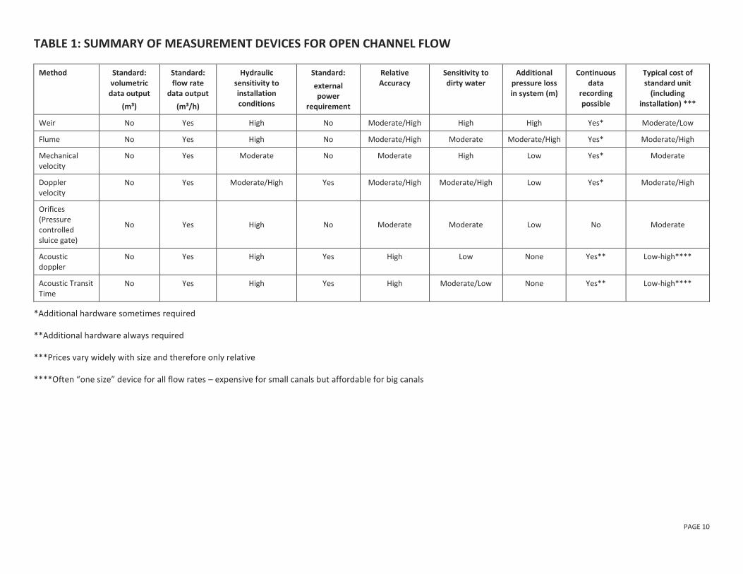
TABLE 1: SUMMARY OF MEASUREMENT DEVICES FOR OPEN CHANNEL FLOW
Method Standard: volumetric
data output
(m³)
Standard: flow rate
data output
(m³/h)
Hydraulic sensitivity to installation conditions
Standard:
external power
requirement
Relative Accuracy
Sensitivity to dirty water
Additional pressure loss in system (m)
Continuous data
recording possible
Typical cost of standard unit
(including installation) ***
Weir No Yes High No Moderate/High High High Yes* Moderate/Low
Flume No Yes High No Moderate/High Moderate Moderate/High Yes* Moderate/High
Mechanical velocity
No Yes Moderate No Moderate High Low Yes* Moderate
Doppler velocity
No Yes Moderate/High Yes Moderate/High Moderate/High Low Yes* Moderate/High
Orifices (Pressure controlled sluice gate)
No Yes High No Moderate Moderate Low No Moderate
Acoustic doppler
No Yes High Yes High Low None Yes** Low-high****
Acoustic Transit Time
No Yes High Yes High Moderate/Low None Yes** Low-high****
*Additional hardware sometimes required
**Additional hardware always required
***Prices vary widely with size and therefore only relative
****Often “one size” device for all flow rates – expensive for small canals but affordable for big canals

BHI 32 (Pty) Ltd