Embed Size (px)
Citation preview
GUIDELINES FOR ROAD DESIGN, CONSTRUCTION, MAINTENANCE AND
SUPERVISION
Volume I: DESIGNING
Section 3: DESIGNING STRUCTURES
DESIGN GUIDELINES (DG 1.3.3) Part 3: GRAVITY RETAINING AND SUPPORTING WALLS


Guidelines for Road Design, Construction, Maintenance and Supervision Gravity retaining walls
RS-FB&H/3CS – DDC 433/94 Volume 1 - Section 3 - Part 3 Strana 3 od 48
INTRODUCTION Retaining and supporting walls are important elements of traffic communications enabling an optimum planning and construction of up-to-date roads and other infrastructural projects in severe geomorphologic conditions and in urban settlements. They essentially influence the construction progress and costs, the traffic safety, durability and functionality, as well as the acceptability of planned interventions in space from the point of view of ecology and environment protection. The Design Guidelines 1.3.3 are divided in four introductory and eight thematic chapters: stone gravity retaining and supporting walls, concrete gravity retaining and supporting walls, reinforced concrete gravity retaining and supporting walls, gravity retaining and supporting wall geostatic analysis, gravity retaining and supporting wall dewatering and backfilling, common methods of gravity retaining and supporting wall construction, and supervision of construction, quality assurance and maintenance of gravity retaining and supporting walls. The present Design Guidelines take account of the former experience in gravity retaining and supporting wall construction and use, of the state-of-the-art professional and theoretical knowledge, of the valid regulations and standards in the field of civil engineering, as well as of the European pre-standards of the geotechnical design. These Design Guidelines are intended for the construction of new roads, reconstruction of existing ones, landslide improvement, and construction of hydro-technical and public utility structures. The Design Guidelines provide some theoretical aspects, practical instructions and constructive features of gravity retaining and supporting walls, which by no means limit any other conceptions and designs of those structures.
Gravity retaining walls Guidelines for Road Design, Construction, Maintenance and Supervision
Strana 4 od 48 Volume 1 - Section 3 - Part 3 RS-FB&H/3CS – DDC 433/94
C O N T E N T S 1 SUBJECT OF DESIGN GUIDELINES..........................................................................................5 2 REFERENCE REGULATIONS.....................................................................................................5 3 EXPLANATION OF TERMS .........................................................................................................5 4 INTRODUCTORY CHAPTER.......................................................................................................7
4.1 Definition, Types and Character of Retaining and Supporting Structures ..........................7 4.2 Geotechnical Categories.....................................................................................................8 4.3 Bases for Retaining and Supporting Structure Design .......................................................9
5 DESIGN RECOMMENDATIONS................................................................................................10 5.1 Design Assumptions .........................................................................................................10 5.2 Methods of Geotechnical Design ......................................................................................10 5.3 Constructive Design Principles .........................................................................................11 5.4 Architectural Design of Retaining and Supporting Structures...........................................12 5.5 Recommendations for Selection of Construction Technology ..........................................12 5.6 Seismic Design of Retaining and Supporting Structures ..................................................13
6 STONE GRAVITY RETAINING AND SUPPORTING WALLS ...................................................14 6.1 General..............................................................................................................................14 6.2 Stone Gravity Retaining and Supporting Wall Design ......................................................16 6.3 Material Requirements and Particularities of Stone Gravity Retaining and Supporting
Wall Construction ..............................................................................................................16 7 CONCRETE GRAVITY RETAINING AND SUPPORTING WALLS ...........................................18
7.1 General..............................................................................................................................18 7.2 Concrete Gravity Retaining and Supporting Wall Design .................................................18 7.3 Material Requirements and Particularities of Concrete Gravity Retaining and Supporting
Wall Construction ..............................................................................................................21 8 REINFORCED CONCRETE GRAVITY RETAINING AND SUPPORTING WALLS ..................23
8.1 General..............................................................................................................................23 8.2 Reinforced Concrete Gravity Retaining and Supporting Wall Design...............................27 8.3 Material Requirements and Particularities of Reinforced Concrete Gravity Retaining and
Supporting Wall Construction............................................................................................28 9 GRAVITY RETAINING AND SUPPORTING WALL GEOSTATIC ANALYSIS ..........................29
9.1 Ultimate Limit States .........................................................................................................29 9.2 Ultimate Limit State Verification ........................................................................................30 9.3 Earth Pressures.................................................................................................................32
10 GRAVITY RETAINING AND SUPPORTING WALL DEWATERING AND BACKFILLING ........36 10.1 Rear Water Drainage ........................................................................................................36 10.2 Surface Water Drainage....................................................................................................39 10.3 Backfilling on Wall Rear Side ............................................................................................40 10.4 Backfilling on Wall Front Side, Protection .........................................................................42
11 COMMON METHODS OF GRAVITY RETAINING AND SUPPORTING WALL CONSTRUCTION .......................................................................................................................42
12 SUPERVISION OF CONSTRUCTION, QUALITY ASSURANCE, AND MAINTENANCE OF GRAVITY RETAINING AND SUPPORTING WALLS.................................................................44 12.1 Supervision and Quality Assurance of Gravity Retaining and Supporting Wall
Construction ......................................................................................................................44 12.2 Gravity Retaining and Supporting Wall Maintenance .......................................................45 12.3 Maintenance Works ..........................................................................................................48
Guidelines for Road Design, Construction, Maintenance and Supervision Gravity retaining walls
RS-FB&H/3CS – DDC 433/94 Volume 1 - Section 3 - Part 3 Strana 5 od 48
1 SUBJECT OF DESIGN
GUIDELINES The present Design Guidelines 1.3.3 Gravity Retaining and Supporting Walls deal with the structures, which transfer the rear earth pressures into the foundation ground. The intention of these Design Guidelines is to provide instructions for selection of a correct shape and type of a structure, which performs its function of stabilizing the rear earth pressures in compliance with the gravity resistance principle. The Guidelines provide the conditions for application of gravity retaining and supporting walls made of different materials in a homogenous section, as well as the geometrical parameters to limit the length, height and other structural elements. In addition, fundamental principles of both static analysis and reinforcement of gravity retaining and supporting walls are indicated. In view of construction, gravity retaining and supporting walls are complex structures. It shall be decided at an early stage of the road design, whether any gravity retaining or supporting wall needs to be foreseen. Both selection and argumentation of a selection of gravity retaining and supporting walls shall be carried out taking into consideration adequate bases. A perfect cooperation of the road designer, the expert in soil mechanics and the civil engineering structure designer is mandatory. Packed rockfills, gabions, etc., which are by their nature gravity retaining and supporting structures as well, are not discussed in the present Guidelines, as no homogenous section is in question in such cases. Different types of stone facings/revetments used to protect embankments (stone pitching, erosion protection on bottom and embankments from with dry rockfills) are also not mentioned in the present Guidelines. The design of both railings and edge beams is discussed in the special Design Guidelines (DG 1.2.2 and DG 1.2.3).
2 REFERENCE REGULATIONS Design, construction, and maintenance of retaining and supporting structures are based on the provisions of different regulations, standards, and guidelines: - Regulations in the field of construction and
structures on the whole; - Regulations for design, construction,
exploitation and maintenance of roads; - Regulations for materials and reliability
verifications of geotechnical structures; - Rulebook of technical norms for foundation
of structures, Official Gazette of SFR Yugoslavia, No. 15-295/90;
- Rulebook of technical norms for concrete and reinforced concrete made of natural and artificial lightweight aggregate filler, Official Gazette of SFR Yugoslavia, No. 15-296/90;
- Rulebook of Yugoslav standards for bases of structural design, Official Gazette of SFR Yugoslavia, No. 49-667/88;
- Rulebook of technical norms for concrete and reinforced concrete in structures exposed to actions of aggressive environment, Official Gazette of SFR Yugoslavia, No. 18/92.
- EN 1990:2002 Eurocode 0 Basis of design;
- prEN 1991 Eurocode 1 Actions on structures;
- prEN 1992 Eurocode 2 Design of concrete structures;
- prEN 1997 Eurocode 7 Geotechnical design;
- prEN 1998 Eurocode 8 Design of structures for earthquake resistance.
3 EXPLANATION OF TERMS Gravity retaining or supporting wall is a structure, which, by its mass and the active earth mass, ensures structural safety (stability). Stone gravity retaining or supporting wall is a structure made of stone blocks of irregular shape, interconnected by the help of concrete to a homogenous integrity, which, by its shape and gravity, transfers the rear earth pressures and live loads into the foundation ground. Concrete gravity retaining or supporting wall is a concrete structure, which, by its shape and gravity, transfers the rear earth pressures and live loads into the foundation ground.
Gravity retaining walls Guidelines for Road Design, Construction, Maintenance and Supervision
Strana 6 od 48 Volume 1 - Section 3 - Part 3 RS-FB&H/3CS – DDC 433/94
Reinforced concrete gravity wall is a reinforced concrete structure, which, by its shape and gravity as well as the active earth mass, transfers the rear earth pressures and live loads into the foundation ground. Retaining wall is a structure located above the carriageway, which, by its shape and gravity, transfers the rear earth pressures into the foundation ground. Supporting wall is a structure located below the carriageway, which, by its shape and gravity, transfers the rear earth pressures and live loads into the foundation ground. Foundation ground is a rock or soil, into which the loading arising from the retaining or supporting wall is transferred. Rear ground is an intact rock or soil to be retained or secured by an adequate wall. Rear backfilling is a soil added and stabilized on the rear side of the wall, either after or simultaneously during the construction works. Front backfilling is a soil added and stabilized on the front side of the wall, either after or simultaneously during the construction works. Rear side is the unexposed part of a retaining or supporting wall. Wall load bearing element is such an element, which enables the transfer of the rear earth pressures to the foundation and the foundation ground. Front wall is the exposed wall side. Rear wall is the unexposed wall side in contact with the soil to be retained. Front foundation toe is a part of foundation extended from the front wall. Rear foundation toe is a part of foundation extended from the rear wall. Rear cantilever is a structural element extended from the rear wall. It provides an additional stability of the retaining or supporting wall. Front cantilever is a structural element extended from the upper half of the front wall. Due to its position, the front cantilever does
not increase the retaining or supporting wall stability. Counterfort is a structural static retaining or supporting wall element, added perpendicularly to the wall front or rear side. Crown is the retaining or supporting wall upper part. Retaining or supporting structure height is the distance between the crown highest point and the foundation lowest point. Retaining or supporting wall height is the distance between the foundation upper level and the crown. Wall thickness is the distance between the wall front and rear side. Foundation width is the distance between the uttermost front and rear point of the foundation in plan. Foundation thickness is the distance between the foundation upper and lower surface. Foundation inclination is the angle of the lower line of the foundation surface to the horizontal. Wall inclination is the angle of the front or the rear wall to the vertical. Foundation depth is the distance between the highest level of the foundation bottom and the lowest level of the ground above it. Height segment is the length of a retaining or supporting wall between adjacent expansion joints. Crown cantilever is a widening of the retaining or supporting wall crown on either the front or the rear side. A crown cantilever enables fixing the edge beam, walkway, and railing. Ground of a low bearing capacity is any ground where the admissible load bearing capacity amounts to less than 200 kPa. Ground of a medium bearing capacity is any ground where the admissible load bearing capacity is within the range of 200 kPa and 400 kPa.

Guidelines for Road Design, Construction, Maintenance and Supervision Gravity retaining walls
RS-FB&H/3CS – DDC 433/94 Volume 1 - Section 3 - Part 3 Strana 7 od 48
Ground of a high bearing capacity is any ground where the admissible load bearing capacity exceeds 400 kPa. Cohesive soils are soils containing grains of up to 0.06 mm, which cannot be seen with an unaided eye. Silts, clays, and organic soils belong to this category. The classification basis is both the liquid limit and the plasticity index. For organic soils, both the colour and the odour shall be taken into consideration as well. Non-cohesive soils are soils containing grains, which size exceeds 0.06 mm. Pure gravels and sands as well as gravels and sands with clayey binder belong to this group. The classification basis is the grain size composition. 4 INTRODUCTORY CHAPTER All types of structures that retain soil, rock or other materials as well as the water, belong to the retaining and supporting structures. Above a certain angle of inclination, slopes of rock or soil cannot be formed without being retained. 4.1 Definition, Types and Character of
Retaining and Supporting Structures In view of purpose, materials, mechanical properties, function in space, and construction methods the following types of retaining and supporting structures can be distinguished: • with regard to the service life retaining and
supporting structures can be permanent or temporary;
• with regard to the material, they can be made of stone, concrete, reinforced concrete, steel or timber, or of a combination of different materials;
• with regard to their position at roads they can be below the carriageway level (supporting walls) or above the carriageway level (retaining walls);
• with regard to their mechanical stiffness retaining and supporting structures can be stiff or deformable. Stiffness is a relative term expressed in terms of the ratio of the ground elasticity to the retaining or supporting structure pliability;
• with regard to the function in space they can retain water as well as soil or rock slopes;
• with regard to the construction method
these structures can be executed: - in an open construction pit, - in the ground, where excavation is
carried out successively one height segment by another,
- from the ground surface in protected excavations,
- in a construction pit including slope protection, or
- from the top downwards by height and length segments.
Two main groups of structures for retaining/supporting the slopes can be distinguished in the design of retaining/supporting measures within the scope of a road construction. 4.1.1 Gravity Retaining and Supporting
Structures Gravity retaining and supporting structures are retaining and supporting walls made of quarry-stone, concrete or reinforced concrete.The soil resistance on the foundation surface is of extreme importance for the structural stability, whereas the resistance at lateral surfaces is less significant and can be omitted in the analyses. Cross-section of such retaining and supporting structures is uniform. However, they can also be locally strengthened with counterforts in the longitudinal direction and/or cantilevers in the transversal direction of the structure. The dead weight of the structure to which a portion of the retained soil can be added in certain cases, as well as the friction retained soil – structure represent an essential contribution to the stability. Typical gravity retaining and supporting structures are shallowly founded massive stone, concrete or reinforced concrete retaining and supporting walls of uniform or variable thicknesses. The massiveness character of such retaining/supporting structures is given by the stiffness of the structure itself as well as by a portion of the retained soil. 4.1.2 Anchored Retaining and Supporting
Structures Both anchored walls and pile walls are discussed in detail in the Design Guidelines 1.3.4.
Gravity retaining walls Guidelines for Road Design, Construction, Maintenance and Supervision
Strana 8 od 48 Volume 1 - Section 3 - Part 3 RS-FB&H/3CS – DDC 433/94
Retaining and supporting structures embedded in ground are relatively thin reinforced concrete walls of a constant or variable thickness, steel and/or wooden sheet piles, pile walls, reinforced concrete columns, walls constructed from the top to the bottom, etc. Such structures can be anchored, stiffened by means of braces or only embedded in the foundation ground. For their determination, the contribution of the earth resistance on lateral surfaces as well as of the ground anchors is essential to ensure the required stability. As a rule, the foundation surface of these structures is not distinctive, and the flexural stiffness plays the most significant role in ensuring the reliability of such retaining or supporting structures. The dead weight of these structures is less important thus it is usually not taken into consideration in the geo-mechanical analyses. 4.2 Geotechnical Categories To determine the extent of required investigations, to assess the appropriateness of a structure and the foreseen construction technology, to estimate the construction costs, as well as to select adequate designers and contractors of retaining and supporting structures, the appointment of the geotechnical category is essential. The latter depends on the assessed risk at the execution of works, the soil type, and potential consequences of eventual design and execution deficiencies to the environment, structures within the influence area as well as to the reliability of executed structures. The geotechnical category shall be determined prior to commencement of the design activities. In the further stages of the investment process the geotechnical category may be changed by maximum one level. By taking into consideration the provisions of several codes and the practical experience, three geotechnical categories need to be introduced: 4.2.1 Geotechnical Category 1 To the geotechnical category 1 minor and simple retaining and supporting structures of a total length up to 3 m belong, however only in cases where the required or planned excavations for foundations do not jeopardize the stability in terms of additional
deformations and exceeding of limit states of nearby structures, infrastructure, phenomena of overall instability of slopes, etc. A classification of retaining and supporting structures in the geotechnical category 1 is only permitted when for the actual foundation ground comparable and documented experiences exist proving that the required procedures of designing and constructing are sufficiently simple to allow an introduction of empirical methods. Non-documented experience won during execution of eventual structures in vicinity must not be taken into consideration. To design such retaining and supporting structures empirical methods are sufficient; the geological-geotechnical conditions and the material properties can be assessed prior to designing on the basis of comparable experiences, ground prospecting, etc. Structures intended for improvement of stability of active, resting and potential landslides must not be classified in this category. 4.2.2 Geotechnical Category 2 To this category retaining and supporting structures or their elements belong where the latter do not represent an unusually high risk as well as extremely unfavourable geotechnical conditions and load cases. Retaining and supporting structures classified in this geotechnical category require precisely determined qualitative and quantitative geotechnical data and results of soil mechanical analyses to fulfil the fundamental criteria of safety and reliability, whereas for laboratory investigations, designing and execution of works standard as well as empirical method may be introduced. To classify a retaining and supporting structure in a higher geotechnical category, geotechnical and not structural reasons are usually decisive. To this category common retaining and supporting structures of a height up to 10 m belong, with or without anchors, in flat land or slope locations, without explicit discontinuities, where no active, resting as well as fossil and potential landslides of greater dimensions or depths above 5 m are noticed. To verify the stability and the limit states, standard methods and computer software are recommendable.

Guidelines for Road Design, Construction, Maintenance and Supervision Gravity retaining walls
RS-FB&H/3CS – DDC 433/94 Volume 1 - Section 3 - Part 3 Strana 9 od 48
4.2.3 Geotechnical Category 3 To the geotechnical category 3 structures of extremely high risk and with special requirements belong. This category is characterized by very severe ground and geo-mechanical conditions and/or by high seismic loading. When classifying the retaining and supporting structures in this category, the following shall be taken into consideration: - risks related to public safety and human
lives; - risks related to severe economic
consequences; - considerable risks due to reduced reliability
of geological and soil mechanical design data;
- high risks related to the reliability of the design solution, when the structural reliability depends on the function of drainage systems or when the reliability of the solution cannot be verified by soil mechanical analyses and calculations, etc.;
- risks due to a very high degree of seismic hazard.
In case that the probability of endangering human lives or causing of such disasters that might affect the national economy is considerably high, each of the mentioned risk factors requires classification of a retaining or supporting structure in the category 3. Structures of the category 3 differ from those of categories 1 and 2 in the extent, quantity and quality of investigations, as well as in the adequate methods of geotechnical analyses, to that quite complicated non-linear and time dependent analytical models, irreplaceable interaction analyses to ensure comparable deformations, stress-strain analyses considering strengthening or softening of soils, experimental models, test loadings as well as observation construction method including execution of measures prescribed in advance belong. The extent and methods of field, laboratory and cabinet investigations generally exceed the common or standardized procedures both quantitatively and qualitatively. For all the retaining and supporting structures classified in the highest geotechnical category, monitoring of the structure and of the ground shall be ensured in the influence area during and after construction.
4.3 Bases for Retaining and Supporting
Structure Design The geotechnical design of retaining and supporting structures includes all the design activities: identification of a stability problem, study of appropriate design solutions, acquiring of required data, soil mechanical analyses, working out, checking and approval of drawings, supervision of construction, and monitoring of the implemented structure. In the road design it is generally difficult to ensure limited interventions in the environment, inclination of slopes and depths of excavations in connection with assessed soil mechanical characteristics of the slopes, which are the primary reasons to study whether the construction of a retaining/supporting structure is justified. The basis for the design of retaining and supporting structures is, similar as it applies to the bridges, the whole of surveying, geological – soil mechanical, seismic, water-economy, road, traffic, meteorological as well as spatial and town planning data on the location for the entire influence area of the project under consideration. For the design of retaining and supporting structures, geological – soil mechanical bases are of particular importance. They will be discussed in detail in special guidelines. Prior to commencement of the design activities, the investor shall provide adequate terms of reference indicating available information, geotechnical categories, data to be acquired by the designer, and other conditions for the design and execution of a retaining or supporting structure. Adequacy, reliability and economy of a design solution directly depend on the knowledge, experiences and qualification of the designer, on accuracy and comprehension of the field data to be provided only by authorized experts in individual spheres permanently cooperating with the designer. Therefore, the latter shall have certain knowledge and experience in all the abovementioned interdisciplinary spheres emphasizing geology, soil mechanics, and construction.
Gravity retaining walls Guidelines for Road Design, Construction, Maintenance and Supervision
Strana 10 od 48 Volume 1 - Section 3 - Part 3 RS-FB&H/3CS – DDC 433/94
5 DESIGN RECOMMENDATIONS 5.1 Design Assumptions When a retaining or supporting structure is being designed, both the client and the structural designer are obliged to ensure the fulfilment of the following design assumptions: • Geotechnical, surveying, hydro-geological,
and seismic design data shall be acquired, documented, and interpreted by taking into consideration the relevant regulations and codes;
• Fundamental documents serving as bases to design retaining and supporting structures are the following: terms of reference, geological – soil mechanical report or documented comparable former experience including exactly stated regulations and codes having been taken into consideration to interpret the data, as well as responsible persons indicated.
• Retaining and supporting structures can be only designed by authorized engineers of an appropriate qualification and proven experience;
• Adequate joining and co-operation of those who prepare the required bases, designers and contractors of retaining and supporting structures shall exist;
• Both in factories and on construction sites, supervision as well as quality control and assurance shall be ensured;
• All the works shall be carried through in accordance with the relevant codes and written instructions provided by experts of adequate knowledge and experience;
• Only certified materials and semi-manufactures can be used;
• Retaining and supporting structures shall be adequately maintained;
A gravity retaining and supporting wall design shall comprise an adequate layout drawing and an elevation at suitable scales. The minimum extent of drawings is a layout, longitudinal and cross sections for different wall elevations as well as appropriate details. The mentioned drawings shall indicate all the dimensions required for staking out and construction of the designed retaining and supporting wall. In the textual part the following shall be indicated: - an argumentation of the selected structure; - bases for the structural shape and
conception;
- fundamental geological characteristics of
the ground where a retaining or supporting wall will be constructed;
The design engineer shall provide all the required instructions for the retaining and supporting wall implementation, and eventual warnings to be taken into account by the contractor. 5.2 Methods of Geotechnical Design In the geotechnical practice, the following four methods can be applied for the retaining and supporting structure design in accordance with the provisions of the Eurocode 7 – Geotechnical Design: • method based on soil mechanical
analyses; • method based on prescriptive measures; • method based on load tests and tests on
experimental models; • observational method. To verify different limit states of individual structural elements a combination of different geotechnical design methods is admissible. 5.2.1 Method Based on Soil Mechanical
analyses In case of a design performed by analytical or numerical methods it shall be verified by calculations on relatively simple mechanical models that all possible limit states, which could affect adversely the bearing resistance, durability and serviceability of a retaining/supporting structure during its design service life, will not be exceeded. 5.2.2 Method of Prescriptive Measures In retaining and supporting structures of the geotechnical category 1, where no reliable physical limit state models are available and, at the same time, a reliability verification by calculation is not necessarily required, the former experience shows that the limit state verification can be replaced by performing of exactly specified measures such as design details, technical specifications, control of materials as well as descriptions of construction methods, protection of structures and their maintenance. In such design methods, the structural designer shall have at his disposal documented local experience being a constituent part of the design documents.
Guidelines for Road Design, Construction, Maintenance and Supervision Gravity retaining walls
RS-FB&H/3CS – DDC 433/94 Volume 1 - Section 3 - Part 3 Strana 11 od 48
The comparability of the geotechnical constructional conditions in the area of the designed retaining/supporting structure shall be verified by the results of qualitative geotechnical investigations. The design method of prescriptive measures is frequently used for surface protection of slopes, and retaining/supporting structures of a height up to 3 m in known geotechnical conditions. 5.2.3 Method Based on Load Tests and
Tests on Experimental Models Load tests and tests on models to verify the fulfilment of the design assumptions of a retaining or supporting structure can be performed on a portion of the actual structure or on models at natural or suitably diminished scale. The results of load tests and experimental model investigations may be used to verify the design assumptions and execution designs of retaining and supporting structures provided that the following features are taken into consideration: • differences in the ground general
conditions (compaction, initial stress, humidity, etc.) between the test loading and the actual structure;
• time effects, especially if the duration of the test is much shorter than the duration of the loading of the actual structure;
• special attention shall be paid to model scales and their effects, especially when very small models are used.
To this design category determination of ground anchor bearing capacity and resistance, creep of anchors, bearing resistance and elasticity (pliability) of piles, etc. belong. 5.2.4 Observational method Where prediction of geotechnical behaviour from the point of view of both ultimate limit states and serviceability limit states of retaining/supporting structures is almost impossible due to severe geotechnical conditions mainly expressed by the initial slope instability and ground water effects, it can be appropriate and advantageous to apply the approach known as the observational method. An essential element of such a design is a planned observation of the retaining or supporting structure and of the influence area of the ground during
construction. This method is generally used for structures of an extreme geotechnical complexity. A possibility of supplemental strengthening shall be foreseen when a retaining/supporting structure is designed in accordance with the observational method. The following requirements shall be specified in the design documents and met before construction is started: Within the realistic possibilities, the acceptable limits of the structural behaviour shall be verified by the soil mechanical analyses. In retaining and supporting structures the acceptable limits of the structural behaviour are determined by allowable absolute and relative ground movements and structural displacements, where the action effects of the structural sections and the crack widths are still within the acceptable limits. A monitoring plan is a constituent part of the execution design where both the monitoring and measurement of all the parameters ensuring design serviceability and functional capability of the structure shall be foreseen. On the basis of the monitoring or measurement results, the actual structural behaviour shall be found out in all those initial construction stages, where, by means of additional measures, such a structural behaviour can be ensured as it has been foreseen by the design. A plan of measures, which must be carried out when the structural behaviour is out of foreseen limits, shall be prepared in advance. Usual additional measures in the retaining and supporting structures are the following: temporary and permanent ground anchors, additional supports or struts, execution of an additional fill in front of the retaining/supporting structure or a relieving behind the retaining/supporting structure, additional drainage measures, grouting of the retained soil, vertical piles, etc. 5.3 Constructive Design Principles The following fundamental constructive principles shall be taken into consideration in the retaining and supporting structure design: • All retaining and supporting structures shall
be conceived and designed to be economical and capable to perform their designed function throughout their service
Gravity retaining walls Guidelines for Road Design, Construction, Maintenance and Supervision
Strana 12 od 48 Volume 1 - Section 3 - Part 3 RS-FB&H/3CS – DDC 433/94
life, provided that normal conditions of construction, supervision, quality assurance, and maintenance are taken into consideration.
• To achieve economical retaining/supporting
structures the latter shall be designed in such a way that the ultimate limit states are not exceeded even in extreme circumstances (centenary water, floods, drainage system failures, etc.). However, for the limit states of less serious consequences (serviceability limit states), it is allowed to consider only the most unfavourable actions in normal exploitation conditions (twenty-years levels of ground water and surface water, proper maintenance of drainage systems to ensure their function, etc.).
• Retaining and supporting structures must
be designed in such a way that eventual consequences of unforeseen events will be proportional to their causes. Therefore, brittle materials such as non-reinforced concrete, extremely compacted gravels, soils stabilized with cement, etc., shall be avoided in the retaining/supporting structure design.
• Such structural systems shall be avoided
that might, upon a change of loading, suddenly change their kinematic properties or their stability without previous warning, which can be evident from increased displacements, deformations and cracks thus leading to a rapid failure.
• Retaining and supporting structures shall
be conceived and designed in such a way that their execution and maintenance are as simple and safe as possible.
5.4 Architectural Design of Retaining and
Supporting Structures For major independent retaining and supporting structures the architectural design and the incorporation in the natural or urban space are an essential constituent part of the design. Therefore, landscaping designers and architects shall be members of the designing group whenever a retaining/supporting structure represents a major intervention in the environment. The responsibility for the architectural design is equally shared among the road designer, the retaining/supporting structure designer and the architect.
5.5 Recommendations for Selection of
Construction Technology From the geotechnical point of view the construction technologies of retaining and supporting structures are defined with regard to the sequence of construction stages, of methods to ensure the required stability of excavations, and of execution of drainage systems and backfilling behind them respectively. The selection of an optimum technology particularly depends on the overall stability of the retaining/supporting structure influence area, sensitivity of structures located in the influence area, stability of temporary local excavations, on the construction costs, available equipment of potential contractors as well as construction time schedule. The following construction technologies are distinguished: Deeply founded retaining/supporting structures constructed predominantly from the existing ground surface: they can be either non-anchored or anchored, or braced. The foreseen interventions in environment (excavations) and the required strengthening (anchors) are carried out progressively in construction stages. To this group pile walls, diaphragms, and jet-grouting retaining/supporting structures belong. Retaining/supporting structures constructed in open separated short cuts and fills, arranged in several height and length segments where the required stability of excavations for the next stages is ensured by anchoring of the already executed segments. To this group belong anchored continuous retaining/supporting walls executed from the top to the bottom, anchored reinforced concrete beams or grids for a permanent protection or temporary retaining of deep excavations of construction pits intended to execute retaining/supporting structures, cuts and covers, etc. Shallowly founded retaining/supporting structures are retaining and supporting walls of stone, concrete or reinforced concrete executed in usual longitudinally arranged segments of 3 m to 6 m in length. Reinforced concrete retaining or supporting walls can be anchored as well.

Guidelines for Road Design, Construction, Maintenance and Supervision Gravity retaining walls
RS-FB&H/3CS – DDC 433/94 Volume 1 - Section 3 - Part 3 Strana 13 od 48
Shallowly founded non-anchored or anchored retaining/supporting structures executed in open unprotected construction pits. The following structures belong to this group: structures where geological-geotechnical conditions allow a safe execution of deep construction pits up to the foreseen foundation level, as well as all the measures to retain road fills or overlays, which are planned to be executed during and after the construction. Concrete retaining/supporting walls, stone retaining/supporting walls, reinforced soils, etc. belong to this group as well. When the costs of a temporary protection of the construction pit exceed 25% of the retaining/supporting wall value, an analysis and comparison of the economy of the construction pit protection with the comparable alternative construction method of a retaining/supporting wall starting from the existing ground surface. Combinations of different retaining/supporting structure construction technologies where the lower part of a retaining/supporting structure is executed beginning from the bottom surface of the construction pit of a limited depth (this is determined by the geological - soil mechanical properties of the location), or from the surface in case of road fill or access road fill construction. To this group massive retaining/supporting walls deeply founded on piles belong. The following factors predominantly influence the selection of the most suitable construction technology: Overall stability of the influence area, which can be assessed as follows: The overall stability has no major influence and will not be endangered during the retaining or supporting structure construction; only local failures of an open slope can be expected. Minor endangering of the overall stability; shallow sliding up to a depth of 2 m can be expected to a limited extent. Significant endangering of the overall stability of long, steep slopes with structures and/or infrastructure, high hydraulic loading, the ground is sensitive to relieving effects, etc. Stability of local excavations: The stability is ensured in compliance with the geotechnical design codes.
The stability conditions of local excavations cannot be verified reliably; a hazard of local failures exists. The safety of local excavations cannot be ensured at all; high sensitivity of ground to the presence of water and to the effects of soil and rock relaxation. Sensitivity of structures in the influence area: There are no significant structures located in the influence area, or they are founded on stable materials, or in cases where geological – soil mechanical conditions indicate that ground movements will positively not occur in the areas of existing structures. Eventual minor ground movements can cause only minor structural damage that cannot affect the structural reliability; considerable ground movements near the structures are less probable. Both safety and reliability of structures in the influence area could be seriously jeopardized due to ground movements; the danger of activating major ground movements and/or structural displacements in case of an open construction pit shall be verified by a soil mechanical analysis. 5.6 Seismic Design of Retaining and
Supporting Structures For the design of retaining and supporting structures along the roads, in conditions of normal seismic hazard, it is sufficient to determine the seismic category of the influence area by considering the data on the design earthquakes for a return period of 475 years. The basic chart of the seismic hazard is used together with the Eurocode 8 - Design of structures for earthquake resistance. For structures of greater risk such as valley dams and water storage reservoirs, it is required to define actual micro-seismic data of the particular location. Retaining and supporting structures shall be designed to perform their function during and after a design earthquake without being seriously damaged. The limit state of a retaining/supporting structure upon an earthquake loading is defined as state where unacceptable permanent damage or permanent displacements of the retaining/supporting structure or sliding earth masses occur. The latter are essential both for structural and functional performance of the structures.
Gravity retaining walls Guidelines for Road Design, Construction, Maintenance and Supervision
Strana 14 od 48 Volume 1 - Section 3 - Part 3 RS-FB&H/3CS – DDC 433/94
Any type of retaining or supporting structures, which are foreseen for static loading, can be selected provided that suitable additional measures are carried through in conditions of a high seismic activity. By an adequate conception and detailing it is necessary to ensure the greatest possible ductility of a structural system (ground stiffness and retaining/supporting structure stiffness shall be comparable for seismic loading, increase of free anchor lengths, etc.). Backfilling materials shall be chosen and compacted in such a way that continuity with existing soils is as uniform as possible. The drainage system located behind the retaining/supporting structure shall be free of damages that might affect its durability and serviceability. It shall be capable to withstand periodical and permanent design displacements. Particularly in non-cohesive soils containing water, a suitable drainage system shall ensure the evacuation of water below the potential failure surface behind the retaining or supporting structure. 6 STONE GRAVITY RETAINING AND
SUPPORTING WALLS 6.1 General Stone gravity retaining and supporting walls are structures made of stone blocks of irregular shapes of dimensions of 0.3 – 0.7 m. By means of concrete, the stone blocks are interconnected into a homogenous entirety, which, by its shape and gravity, transfers the rear earth pressures and live loads into the foundation ground. Stone gravity retaining and supporting walls are so conceived as to keep the resultant of the action forces in the core of the section. They are mostly used as retaining structures, i.e. structures above the carriageway level, whereas to a smaller extent as supporting structures, i.e. below the carriageway level. The ration of stone blocks to the filling concrete is between 60:40 and 30:70. As compressive stresses act in the wall section, no steel reinforcement is required.
Usually, the height of stone gravity retaining/supporting walls amounts to 1.0 – 6.0 m, and depends in particular on the foundation soil grade. Stone gravity retaining and supporting walls are particularly economical in places where a sufficient quantity of suitable stone material is available, and where the ground configuration (slope inclination) allows construction of a structure with minor inclinations of walls. Due to the characteristics in view of their shape, stone gravity walls are appropriate for retaining or supporting structures both above and below the carriageway, where the intervention in the retained soil is limited, yet it is possible to carry out the inclinations of excavated slopes up to the value of the inclination of the wall rear side, as these structures are, as a rule, executed in accordance with the contact construction principles. Due to their natural appearance (the front is composed of selected large stone blocks), stone gravity walls are suitable particularly to non-urban locations where their incorporation in the natural milieu is essential. For urban regions, such retaining/supporting structures are more appropriate, which front walls are additionally finished with stone facings made of minor elements. Other solutions are feasible as well.

Guidelines for Road Design, Construction, Maintenance and Supervision Gravity retaining walls
Fig.6.1: Stone gravity retaining wall, including staking out data
Fig.6.2: Stone gravity supporting wall, including staking out data
RS-FB&H/3CS – DDC 433/94 Volume 1 - Section 3 - Part 3 Strana 15 od 48
Gravity retaining walls Guidelines for Road Design, Construction, Maintenance and Supervision 6.2 Stone Gravity Retaining and
Supporting Wall Design Stone gravity walls are executed up to the front wall inclination of 3 : 1, whilst the inclination of the rear wall is, as a rule, slightly smaller, thus their mutual difference amounts to at least 5°. Due to such conception in view of the shape, stone gravity walls are generally not widened at the bottom of the structure (foundation). The minimum thickness of a stone retaining/supporting wall is conditioned by the size of concrete blocks, which the retaining/supporting structure consists of. The minimum dimension of a stone block amounts to 0.5 m and 0.1 m3 respectively. Generally, the wall crown width amounts to 0.70 m. The section thickness increases by the depth, with regard to the difference between the inclination of the front wall and that of the rear wall. Therefore, such a difference shall be taken into consideration in selecting the inclination of both walls, as to ensure a sufficient width of the foundation surface at the bottom of the structure, thus no additional widening in either front or rear direction is required. The foundation part of stone gravity walls shall be constructed of C 25/30 concrete. The inclination of the lower surface of the concrete foundation shall be within the limits of 10 – 20% (1:10 – 1:5) towards the rear wall, whereas the inclination of the upper surface is identical in the sense of a mirror image. The thickness of the concrete foundation amounts to 0.50 m. The foundation depth is conditioned by the geological soil composition and by the freezing depth. Where such structures are executed in water, the minimum foundation depth shall be 1.50 m, or the foundation shall be embedded in rock by 0.5 – 1.0 m. The longitudinal course of the foundation surface of stone gravity walls shall be shaped continuously up to an inclination of 20%. Beyond this limit it is necessary to foresee suitable terracing, which shall be adjusted to the longitudinal fall of the ground or foundation soil.
6.3 Material Requirements and Particularities of Stone Gravity Retaining and Supporting Wall Construction
Stone material as basic constructive element of stone gravity walls shall comply with the following requirements: - stone blocks shall be freeze resistant; - the size of individual blocks shall be at
least 0.5 m and 0.1 m3 respectively; - stone blocks shall be perfectly clean prior
to being placed as to ensure a sufficient adhesion of the concrete.
As binding or filling material, the concrete shall comply with the following requirements: - concrete mixture of C 25/30 grade; - the concrete mixture shall be prepared is
such a way that it can be cast without erecting any formwork.
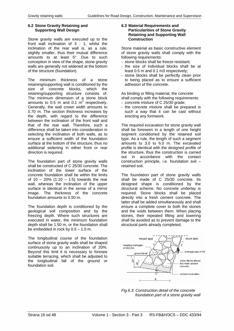
The required excavation for stone gravity wall shall be foreseen in a length of one height segment conditioned by the retained soil type. As a rule, the length of such a segment amounts to 3.0 to 6.0 m. The excavated profile is identical with the designed profile of the structure, thus the construction is carried out in accordance with the contact construction principle, i.e. foundation soil – retained soil. The foundation part of stone gravity walls shall be made of C 25/30 concrete. Its designed shape is conditioned by the structural scheme. No concrete underlay is required. Stone blocks shall be placed directly into a fresh cement concrete. The latter shall be added simultaneously and shall ensure a complete cover to both the stones and the voids between them. When placing stones, their repeated lifting and lowering shall be avoided as to prevent damage to the structural parts already completed.
Fig.6.3: Construction detail of the concrete
foundation part of a stone gravity wall
Strana 16 od 48 Volume 1 - Section 3 - Part 3 RS-FB&H/3CS – DDC 433/94

Guidelines for Road Design, Construction, Maintenance and Supervision Gravity retaining walls Concrete blocks shall be piled up in such a way that the largest and the most even element face is oriented towards the front. The joints between stone blocks shall be deepened by 10 – 15 cm and can be subsequently either filled up with a mixture of humus and grass seeds or finished with cement mortar. Both vertical and horizontal construction joints are admitted. The vertical joints depend on the length of the height segment, whilst the horizontal ones on the work progress on individual height segment. The construction joints do not require any treatment in view of foreseeing expansion joints (vertical joints) or sealing to achieve a watertight structure. Particularly in case of vertical construction progress it is necessary to prevent eventual soil failures, which might dirty the construction joint surface and obstruct an adequate adhesion to the part already completed. If this happens in spite of all precautions, preliminary cleaning shall be carried through.
Fig.6.4: Construction detail of stone gravity
wall The finishing of the crown of a stone gravity wall depends in particular on the wall location: above the carriageway or directly below the carriageway. The crowns of the retaining walls shall be made of such stone blocks as to enable levelling of the previously placed larger concrete blocks. In this way, an adequate evenness in the longitudinal direction is ensured, whereas in the transverse direction a fall of 3% towards the rear wall is achieved. On the rear wall, a channel to evacuate precipitation water shall be constructed.
Fig.6.5: Detail of the crown of a stone gravity retaining wall Where a stone gravity supporting wall is constructed directly below the carriageway, the crown shall be made of C 25/30 concrete. The shape of the upper concrete part is conditioned by an adequate anchoring of edge beams executed subsequently.
Fig.6.6: Detail of the crown of a stone gravity supporting wall
RS-FB&H/3CS – DDC 433/94 Volume 1 - Section 3 - Part 3 Strana 17 od 48
Gravity retaining walls Guidelines for Road Design, Construction, Maintenance and Supervision
Strana 18 od 48 Volume 1 - Section 3 - Part 3 RS-FB&H/3CS – DDC 433/94
7 CONCRETE GRAVITY RETAINING
AND SUPPORTING WALLS 7.1 General Concrete gravity walls are concrete structures, which, by its shape and gravity, transfer the rear earth pressures and live loads into the foundation ground. They are so conceived as to keep the resultant of the action forces in the core of the section, therefore no reinforcement is required. The maximum height of concrete gravity walls amounts to 8.0 – 10.0 m and depends particularly on the foundation soil grade. As a rule, the rear wall is inclined towards the rear as to reduce the earth pressure. Concrete gravity walls are economical especially in cases where the ground inclinations are significant, thus stone gravity walls would be inappropriate. The same also applies when there is no suitable stone material available in the vicinity. Retaining and supporting structures with a vertical rear wall are applicable to normal ground inclinations and a normal foundation soil grade, whilst those with an inclined rear wall to major ground inclinations and a ground of a high load bearing capacity. Due to their shape characteristics, concrete gravity walls are suitable to both retaining and supporting walls, where the intervention in the retained soil should be as insignificant as possible, thus the backfill behind the rear wall is as inconsiderable as possible after completed casting. The contact concreting of concrete gravity walls is carried out quite rarely; it is exceptionally foreseen when new wall segments are added to the existing walls. Due to their appearance (large exposed concrete surfaces), concrete gravity walls are suitable especially to locations where the incorporation in the natural environment is not very essential, or where a wall is incorporated in a milieu, which already comprises similar structures. To implement aesthetic requirements, the exposed surfaces of concrete walls shall be adequately finished by means of subsequent stone facing, precedent treatment of formwork elements or simultaneous erecting of a stone facing.
7.2 Concrete Gravity Retaining and
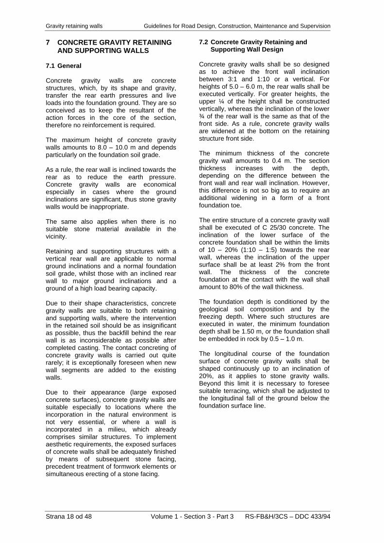
Supporting Wall Design Concrete gravity walls shall be so designed as to achieve the front wall inclination between 3:1 and 1:10 or a vertical. For heights of 5.0 – 6.0 m, the rear walls shall be executed vertically. For greater heights, the upper ¼ of the height shall be constructed vertically, whereas the inclination of the lower ¾ of the rear wall is the same as that of the front side. As a rule, concrete gravity walls are widened at the bottom on the retaining structure front side. The minimum thickness of the concrete gravity wall amounts to 0.4 m. The section thickness increases with the depth, depending on the difference between the front wall and rear wall inclination. However, this difference is not so big as to require an additional widening in a form of a front foundation toe. The entire structure of a concrete gravity wall shall be executed of C 25/30 concrete. The inclination of the lower surface of the concrete foundation shall be within the limits of 10 – 20% (1:10 – 1:5) towards the rear wall, whereas the inclination of the upper surface shall be at least 2% from the front wall. The thickness of the concrete foundation at the contact with the wall shall amount to 80% of the wall thickness. The foundation depth is conditioned by the geological soil composition and by the freezing depth. Where such structures are executed in water, the minimum foundation depth shall be 1.50 m, or the foundation shall be embedded in rock by 0.5 – 1.0 m. The longitudinal course of the foundation surface of concrete gravity walls shall be shaped continuously up to an inclination of 20%, as it applies to stone gravity walls. Beyond this limit it is necessary to foresee suitable terracing, which shall be adjusted to the longitudinal fall of the ground below the foundation surface line.
Guidelines for Road Design, Construction, Maintenance and Supervision Gravity retaining walls
Fig. 7.1: Concrete gravity retaining wall with a vertical rear wall
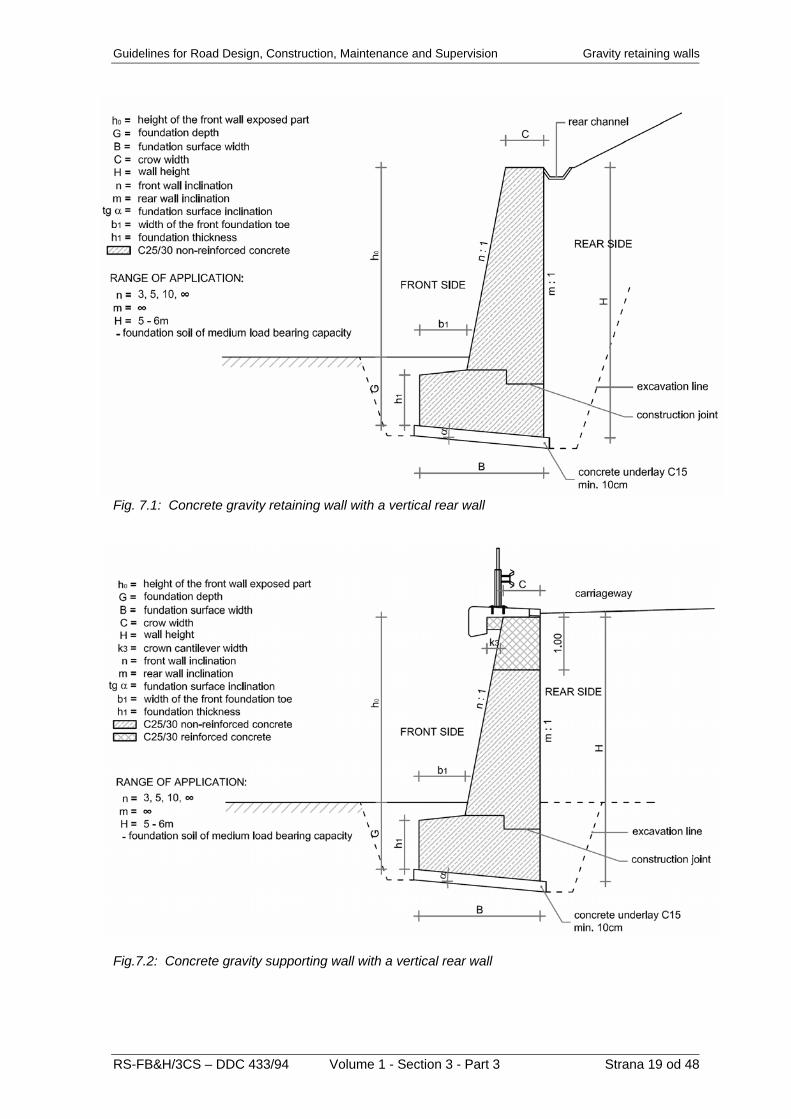
Fig.7.2: Concrete gravity supporting wall with a vertical rear wall
RS-FB&H/3CS – DDC 433/94 Volume 1 - Section 3 - Part 3 Strana 19 od 48

Gravity retaining walls Guidelines for Road Design, Construction, Maintenance and Supervision
Fig.7.3: Concrete gravity retaining wall with an inclined rear wall, including staking out data
Fig.7.4: Concrete gravity supporting wall with an inclined rear wall, including staking out data
Strana 20 od 48 Volume 1 - Section 3 - Part 3 RS-FB&H/3CS – DDC 433/94
Guidelines for Road Design, Construction, Maintenance and Supervision Gravity retaining walls 7.3 Material Requirements and
Particularities of Concrete Gravity Retaining and Supporting Wall Construction
As a basic material, the concrete shall comply with the following requirements: - concrete mixture grade shall be C 25/30; - the concrete mixture shall be so prepared
as to enable its adequate casting into the formwork;
- formwork materials and finishing of exposed surfaces shall comply with the conditions for exposed and non-exposed concrete surfaces in accordance with the D.G. 1.2.10 Formwork, Finishing, and Facing of Concrete Surfaces
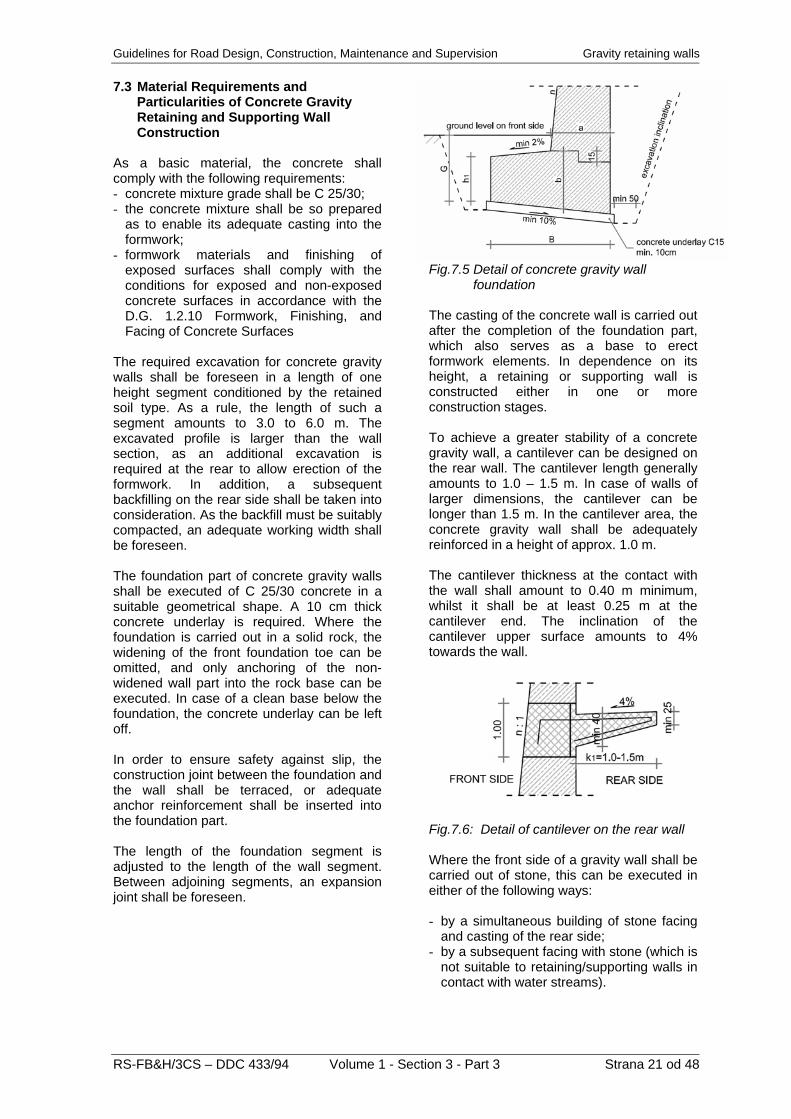
The required excavation for concrete gravity walls shall be foreseen in a length of one height segment conditioned by the retained soil type. As a rule, the length of such a segment amounts to 3.0 to 6.0 m. The excavated profile is larger than the wall section, as an additional excavation is required at the rear to allow erection of the formwork. In addition, a subsequent backfilling on the rear side shall be taken into consideration. As the backfill must be suitably compacted, an adequate working width shall be foreseen. The foundation part of concrete gravity walls shall be executed of C 25/30 concrete in a suitable geometrical shape. A 10 cm thick concrete underlay is required. Where the foundation is carried out in a solid rock, the widening of the front foundation toe can be omitted, and only anchoring of the non-widened wall part into the rock base can be executed. In case of a clean base below the foundation, the concrete underlay can be left off. In order to ensure safety against slip, the construction joint between the foundation and the wall shall be terraced, or adequate anchor reinforcement shall be inserted into the foundation part. The length of the foundation segment is adjusted to the length of the wall segment. Between adjoining segments, an expansion joint shall be foreseen.
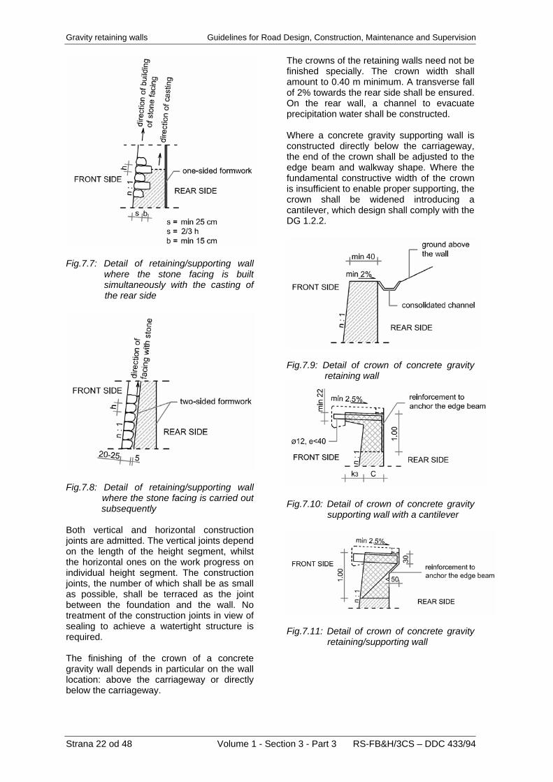
Fig.7.5 Detail of concrete gravity wall foundation The casting of the concrete wall is carried out after the completion of the foundation part, which also serves as a base to erect formwork elements. In dependence on its height, a retaining or supporting wall is constructed either in one or more construction stages. To achieve a greater stability of a concrete gravity wall, a cantilever can be designed on the rear wall. The cantilever length generally amounts to 1.0 – 1.5 m. In case of walls of larger dimensions, the cantilever can be longer than 1.5 m. In the cantilever area, the concrete gravity wall shall be adequately reinforced in a height of approx. 1.0 m. The cantilever thickness at the contact with the wall shall amount to 0.40 m minimum, whilst it shall be at least 0.25 m at the cantilever end. The inclination of the cantilever upper surface amounts to 4% towards the wall.
Fig.7.6: Detail of cantilever on the rear wall Where the front side of a gravity wall shall be carried out of stone, this can be executed in either of the following ways: - by a simultaneous building of stone facing
and casting of the rear side; - by a subsequent facing with stone (which is
not suitable to retaining/supporting walls in contact with water streams).
RS-FB&H/3CS – DDC 433/94 Volume 1 - Section 3 - Part 3 Strana 21 od 48
Gravity retaining walls Guidelines for Road Design, Construction, Maintenance and Supervision
Fig.7.7: Detail of retaining/supporting wall where the stone facing is built simultaneously with the casting of the rear side
Fig.7.8: Detail of retaining/supporting wall where the stone facing is carried out subsequently Both vertical and horizontal construction joints are admitted. The vertical joints depend on the length of the height segment, whilst the horizontal ones on the work progress on individual height segment. The construction joints, the number of which shall be as small as possible, shall be terraced as the joint between the foundation and the wall. No treatment of the construction joints in view of sealing to achieve a watertight structure is required. The finishing of the crown of a concrete gravity wall depends in particular on the wall location: above the carriageway or directly below the carriageway.
The crowns of the retaining walls need not be finished specially. The crown width shall amount to 0.40 m minimum. A transverse fall of 2% towards the rear side shall be ensured. On the rear wall, a channel to evacuate precipitation water shall be constructed. Where a concrete gravity supporting wall is constructed directly below the carriageway, the end of the crown shall be adjusted to the edge beam and walkway shape. Where the fundamental constructive width of the crown is insufficient to enable proper supporting, the crown shall be widened introducing a cantilever, which design shall comply with the DG 1.2.2.
Fig.7.9: Detail of crown of concrete gravity retaining wall
Fig.7.10: Detail of crown of concrete gravity supporting wall with a cantilever
Fig.7.11: Detail of crown of concrete gravity retaining/supporting wall
Strana 22 od 48 Volume 1 - Section 3 - Part 3 RS-FB&H/3CS – DDC 433/94

Guidelines for Road Design, Construction, Maintenance and Supervision Gravity retaining walls
RS-FB&H/3CS – DDC 433/94 Volume 1 - Section 3 - Part 3 Strana 23 od 48
8 REINFORCED CONCRETE
GRAVITY RETAINING AND SUPPORTING WALLS
8.1 General Reinforced concrete gravity wall is a reinforced concrete structure, which, by its shape and gravity as well as the active earth mass, transfers the rear earth pressures and live loads into the foundation ground. In comparison with a concrete gravity wall, a reinforced concrete gravity wall represents a saving of the wall thickness, partly or completely equalized by arranging the front or rear foundation toe, or rear cantilever. The following reinforced concrete gravity walls can be distinguished: - reinforced concrete walls with a foundation
on the front side, and - angular walls of smaller thickness, with or
without counterforts, and with a relatively wide foundation slab.
Reinforced concrete gravity walls can be executed either above (retaining walls) or below the carriageway (supporting walls), in particular in a ground of a low bearing capacity. Reinforced concrete angular gravity walls are suitable especially in cases where a new fill is formed at the rear. Angular walls are seldom used as retaining walls, as they require a major intervention in the retained rock, which is not desired. Reinforced concrete gravity walls shall be executed of C 25/30 concrete and of reinforcement, which is specified on the basis of the design of critical structural sections. The maximum height of reinforced concrete gravity walls shall amount to 10.0 – 12.0 m. Angular reinforced concrete walls with counterforts can be even higher. The height depends particularly on the foundation soil grade. The application of reinforced concrete gravity walls is inevitable in cases where massive retaining/supporting walls cannot be executed for spatial restraints, and where such a solution is economically justified. Reinforced concrete gravity walls are also suitable to foundation soils of lower bearing capacity where the massive retaining structures are not able to meet the criterion of the foundation soil bearing capacity. Exceptionally, pile or well foundation can be foreseen in case of a poor foundation soil.
Angular reinforced concrete gravity walls are particularly suitable as supporting walls in cases where new fills are constructed and where the ground to execute a fill is limited. Reinforced concrete walls are economical in view of concrete consumption and suitable to foundation ground of low bearing capacity, as pressures acting on the ground are reduced due to a large foundation area. An additional reduction or a more favourable pressure distribution can be ensured introducing counterforts. Reinforced concrete angular walls with counterforts on the rear side represent a special type of angular walls. They are appropriate for walls of greater heights, as the dimensions, reinforcement quantity, stresses and deformations are reduced applying such walls. The counterforts of 0.5 – 0.7 m in thickness shall be spaced at 3-5 m. Their shape is adjusted to the dimensions of both the front wall and foundation. The counterfort top is situated 50 – 70 cm below the road level, thus the pavement structure is not disturbed. The wall crown can be executed either without or with a cantilever, which is adjusted to the shoulder width, or, where the wall is in contact with a bridge, to the walkway width. Execution of a fill at the angular wall rear with counterforts is difficult. Stone or gravel material is favourable, as it can be compacted easier. In certain cases of lower angular walls where an even rear surface is required, the counterforts can also be foreseen on the front, i.e. exposed side, which requires a widening of the foundation in this direction. In view of the shape, to reinforced concrete gravity walls similar features apply as to concrete gravity walls. Therefore, reinforced concrete gravity walls with unfinished large exposed concrete surfaces are particularly suitable to locations where the incorporation in the natural surroundings is not very important, or where a wall is incorporated in a milieu already comprising similar structures. To fulfil the aesthetical requirements, the exposed surfaces of reinforced concrete gravity walls can be adequately finished either by a subsequent stone facing or by a preliminary treatment of formwork elements.
Gravity retaining walls Guidelines for Road Design, Construction, Maintenance and Supervision
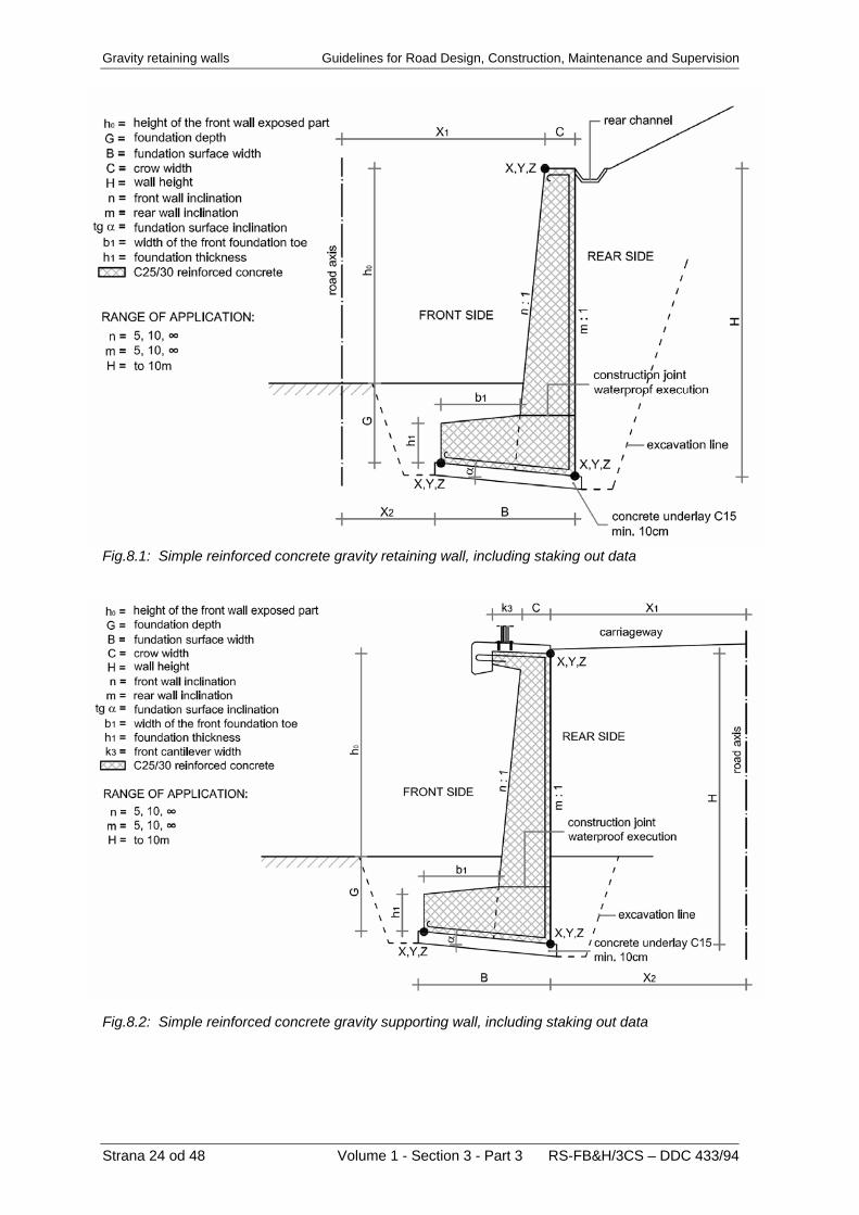
Fig.8.1: Simple reinforced concrete gravity retaining wall, including staking out data
Fig.8.2: Simple reinforced concrete gravity supporting wall, including staking out data
Strana 24 od 48 Volume 1 - Section 3 - Part 3 RS-FB&H/3CS – DDC 433/94
Guidelines for Road Design, Construction, Maintenance and Supervision Gravity retaining walls
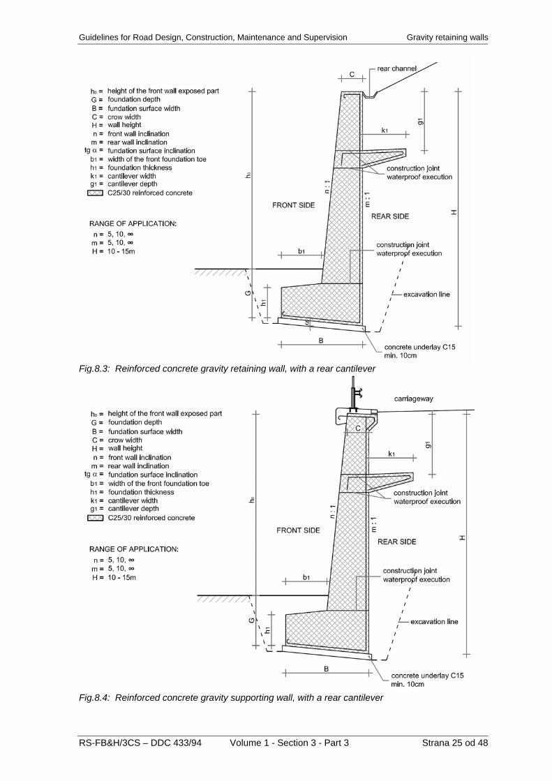
Fig.8.3: Reinforced concrete gravity retaining wall, with a rear cantilever
Fig.8.4: Reinforced concrete gravity supporting wall, with a rear cantilever
RS-FB&H/3CS – DDC 433/94 Volume 1 - Section 3 - Part 3 Strana 25 od 48

Gravity retaining walls Guidelines for Road Design, Construction, Maintenance and Supervision
Fig.8.5: Angular reinforced concrete gravity retaining wall, including staking out data
Fig. 8.6: Angular reinforced concrete gravity supporting wall, including staking out data
Strana 26 od 48 Volume 1 - Section 3 - Part 3 RS-FB&H/3CS – DDC 433/94

Guidelines for Road Design, Construction, Maintenance and Supervision Gravity retaining walls
Fig.8.7: Angular reinforced concrete gravity supporting wall, with counterforts 8.2 Reinforced Concrete Gravity Retaining
and Supporting Wall Design Reinforced concrete gravity walls shall be so designed as to achieve the front wall inclination between 5:1 and 1:10 or a vertical. As a rule, rear walls shall be executed vertically. Reinforced concrete gravity retaining/supporting walls are always widened at the bottom on the retaining/supporting structure front side.
Fig.8.8: Some possibilities of foundation
design to increase positive interaction between the wall and the ground
The minimum thickness of the reinforced concrete gravity wall amounts to 0.4 m. The section thickness increases with the height, depending on the difference between the front wall and rear wall inclination. However, this difference is always such as to require an additional widening in a form of a front foundation toe, or both front and rear foundation toe in case of an angular wall. The entire structure of a reinforced concrete gravity wall shall be executed of C 25/30 concrete. The inclination of the lower surface of the foundation shall be within the limits of 10 – 20% (1:10 – 1:5) towards the rear wall. The inclination of the upper surface of the foundation toes shall be at least 2% from the front wall, or from the rear wall in case of an angular wall. The thickness of the concrete foundation at the contact with the wall shall be equal to the wall thickness at that height. The foundation depth is conditioned by the geological soil composition and by the freezing depth. Where such structures are executed in water, the minimum foundation depth shall be 1.50 m, or the foundation shall be embedded in rock by 0.5 – 1.0 m. The longitudinal course of the foundation surface of reinforced concrete gravity walls shall be shaped continuously up to an inclination of 20%, as it applies to both stone and concrete gravity walls. Beyond this limit it is necessary to foresee suitable terracing, which shall be adjusted to the longitudinal fall of the ground below the foundation surface line.
RS-FB&H/3CS – DDC 433/94 Volume 1 - Section 3 - Part 3 Strana 27 od 48

Gravity retaining walls Guidelines for Road Design, Construction, Maintenance and Supervision 8.3 Material Requirements and
Particularities of Reinforced Concrete Gravity Retaining and Supporting Wall Construction
As a basic material, the concrete shall comply with the following requirements: - concrete mixture grade shall be C 25/30; - the concrete mixture shall be so prepared
as to enable its adequate casting into the formwork in compliance with the principle of waterproof concrete;
- formwork materials and finishing of exposed surfaces shall comply with the conditions for exposed and non-exposed concrete surfaces in accordance with the D.G. 1.2.10 Formwork, Finishing, and Facing of Concrete Surfaces.
The required excavation for reinforced concrete gravity walls shall be foreseen in a length of one height segment conditioned by the retained soil type. As a rule, the length of such a segment amounts to 3.0 to 6.0 m. The excavated profile is larger than the wall section, as an additional excavation is required at the rear to allow erection of the formwork. In addition, a subsequent backfilling on the rear side shall be taken into consideration. As the backfill must be suitably compacted, an adequate working width shall be foreseen. Angular reinforced concrete gravity walls are generally used where fills behind the walls are executed subsequently, thus the excavation at the rear is minimum. The foundation part of reinforced concrete gravity walls shall be executed of C 25/30 concrete in a suitable geometrical shape. A 10 cm thick concrete underlay is required. In case of a clean base below the foundation, the concrete underlay can be left off. The construction joint between the foundation and the wall can be carried out evenly, as eventual slip is prevented by the reinforcement.
Fig.8.9: Detail of reinforced concrete gravity wall foundation
The casting of the concrete wall is carried out after the completion of the foundation part, which also serves as a base to erect formwork elements. In dependence on its height, a retaining/supporting wall is constructed either in one or more construction stages. To achieve a greater stability of a reinforced concrete gravity wall, a cantilever can be designed on the rear wall. The cantilever length generally amounts to 1.0 – 1.5 m. In case of walls of larger dimensions, the cantilever can be longer than 1.5 m. The cantilever thickness at the contact with the wall shall amount to 0.40 m minimum, whilst it shall be at least 0.25 m at the cantilever end. The inclination of the cantilever upper surface amounts to 4% towards the wall.
Fig.8.10: Detail of reinforced concrete gravity wall Where the front side of a gravity wall shall be carried out of stone, this can be only executed by a subsequent facing with stone (which is not suitable to retaining and supporting walls in contact with a water stream).
Fig.8.11: Detail of reinforced concrete gravity wall with a rear cantilever
Strana 28 od 48 Volume 1 - Section 3 - Part 3 RS-FB&H/3CS – DDC 433/94
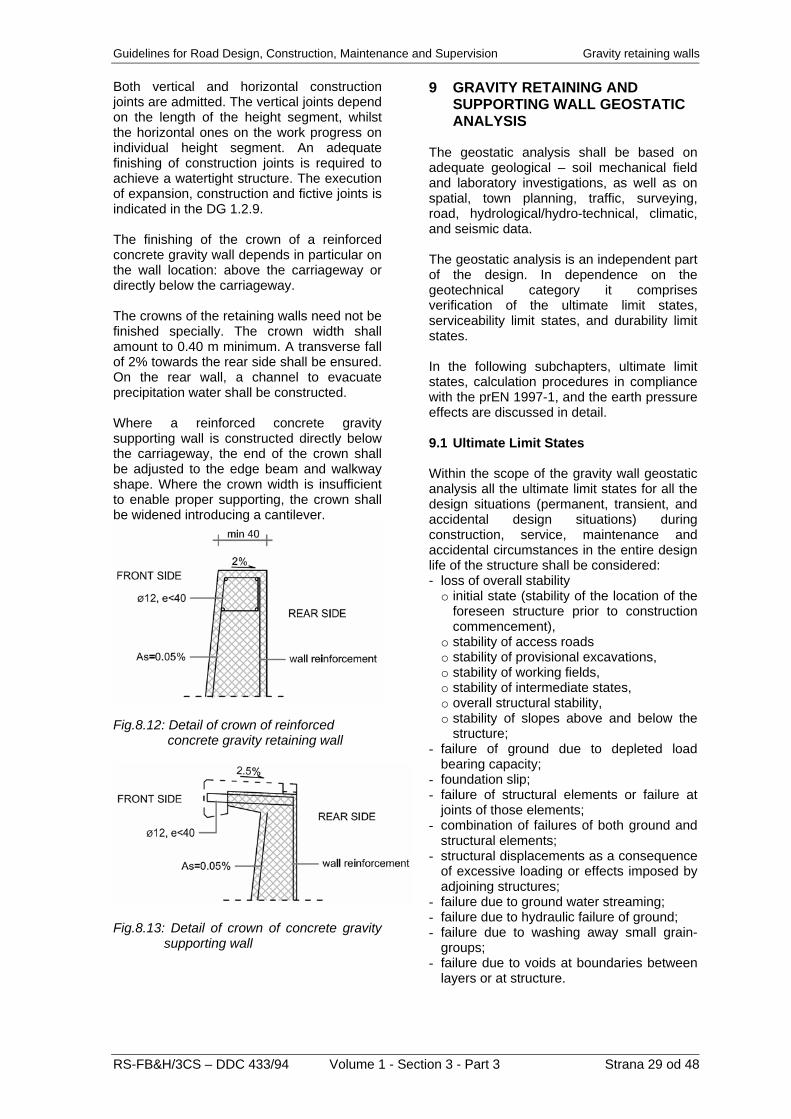
Guidelines for Road Design, Construction, Maintenance and Supervision Gravity retaining walls Both vertical and horizontal construction joints are admitted. The vertical joints depend on the length of the height segment, whilst the horizontal ones on the work progress on individual height segment. An adequate finishing of construction joints is required to achieve a watertight structure. The execution of expansion, construction and fictive joints is indicated in the DG 1.2.9. The finishing of the crown of a reinforced concrete gravity wall depends in particular on the wall location: above the carriageway or directly below the carriageway. The crowns of the retaining walls need not be finished specially. The crown width shall amount to 0.40 m minimum. A transverse fall of 2% towards the rear side shall be ensured. On the rear wall, a channel to evacuate precipitation water shall be constructed. Where a reinforced concrete gravity supporting wall is constructed directly below the carriageway, the end of the crown shall be adjusted to the edge beam and walkway shape. Where the crown width is insufficient to enable proper supporting, the crown shall be widened introducing a cantilever.
Fig.8.12: Detail of crown of reinforced concrete gravity retaining wall
Fig.8.13: Detail of crown of concrete gravity supporting wall
9 GRAVITY RETAINING AND
SUPPORTING WALL GEOSTATIC ANALYSIS
The geostatic analysis shall be based on adequate geological – soil mechanical field and laboratory investigations, as well as on spatial, town planning, traffic, surveying, road, hydrological/hydro-technical, climatic, and seismic data. The geostatic analysis is an independent part of the design. In dependence on the geotechnical category it comprises verification of the ultimate limit states, serviceability limit states, and durability limit states. In the following subchapters, ultimate limit states, calculation procedures in compliance with the prEN 1997-1, and the earth pressure effects are discussed in detail. 9.1 Ultimate Limit States Within the scope of the gravity wall geostatic analysis all the ultimate limit states for all the design situations (permanent, transient, and accidental design situations) during construction, service, maintenance and accidental circumstances in the entire design life of the structure shall be considered: - loss of overall stability
o initial state (stability of the location of the foreseen structure prior to construction commencement),
o stability of access roads o stability of provisional excavations, o stability of working fields, o stability of intermediate states, o overall structural stability, o stability of slopes above and below the
structure; - failure of ground due to depleted load
bearing capacity; - foundation slip; - failure of structural elements or failure at
joints of those elements; - combination of failures of both ground and
structural elements; - structural displacements as a consequence
of excessive loading or effects imposed by adjoining structures;
- failure due to ground water streaming; - failure due to hydraulic failure of ground; - failure due to washing away small grain-
groups; - failure due to voids at boundaries between
layers or at structure.
RS-FB&H/3CS – DDC 433/94 Volume 1 - Section 3 - Part 3 Strana 29 od 48

Gravity retaining walls Guidelines for Road Design, Construction, Maintenance and Supervision For the limit state verification the following shall be particularly taken into consideration:
9.2 Ultimate Limit State Verification The common equation to verify the ultimate limit states is as follows:
- variation of ground water level and pore
pressures by time and location; - inadmissible leaking below and through the
structure; udud RE ,, ≤ (9.1) - variation of soil characteristics by time and
location; Ed,u = design value of effects of actions at the considered limit state - variation of magnitude and combination of
actions; Rd,u= comparable design resistances activated at the considered limit state. - excavations and erosion below the
structure; In particular the following loads apply: - backfilling behind the structure; - rear earth pressure, - effect imposed by eventual adjacent
structures, foreseen additional loading and disburdening;
- weight of the structure, - additional loading (e.g. traffic, actions on
bridges), - ground movements due to ground settlements, freezing, and similar sources. - hydrostatic pressures,
- undulation and ice forces, - seeping, The actions of ice and undulation are not
considered simultaneously. - impact forces, - thermal actions, - seismic load. For the analysis of the stability of location
of a retaining/supporting structure, in particular the following causes of the loss of stability shall be considered:
Both the design values of actions Ed and design values of resistances Rd are assessed by partial factors: - loss of overall stability of the ground and
neighbouring structures; - γF partial factors for actions Frep, - γE partial factors for action effects E, - inadmissible ground movements as a
consequence of shear deformations, settlements, uplifts or vibrations;
- γM partial factors for material properties X, - γR partial factors for resistances R. - failure due to internal and external erosion; The design static analysis in accordance with the prEN1997-1 foresees three methods (approach 1, 2, and 3), differing one from another in the combination of partial factors for actions, resistances, and material properties. The partial factors are indicated in the Annex A to the prEN1997-1 for structural limit states STR and geotechnical limit states GEO. To non-anchored gravity structures the following tables apply:
- failure due to hydraulic failure of the ground or due to buoyancy;
- damages or loss of serviceability of adjacent buildings, roads or installations due to ground movements;
- failures as a consequence of a slip or an overturn of rigid rock blocks;
- earthquake.
- A.2.1 for actions or action effects - A.2.2 for material properties - A.2.3.5, A.2.3.6 for resistances
Table 9.1: Partial factors for actions (γF) or action effects (γE), prEN1997-1, A.2.1
Series ACTION TYPE Symbol A1 A2
Unfavourable 1.35 1.0 PERMANENT Favourable
γG1.0 1.0
Unfavourable 1.5 1.3 VARIABLE Favourable
γQ0 0
Strana 30 od 48 Volume 1 - Section 3 - Part 3 RS-FB&H/3CS – DDC 433/94

Guidelines for Road Design, Construction, Maintenance and Supervision Gravity retaining walls
RS-FB&H/3CS – DDC 433/94 Volume 1 - Section 3 - Part 3 Strana 31 od 48
Table 9.2: Partial factors for soil parameters (γM), prEN1997-1, A.2.2
Series PROPERTY Symbol M1 M2
Shear angle (*, **) γϕ 1.0 1.25 Cohesion (*) γc 1.0 1.25
Non-drained strength γcu 1.0 1.4 Mono-axial strength γqu 1.0 1.4
Volume weight γσ 1.0 1.0 * drained condition ** safety to tan (ϕ)
Table 9.3: Partial factors for resistances (γR) for retaining/supporting structures, prEN1997-1, A.2.3.5
Series RESISTANCE Symbol
R1 R2 R3 Bearing capacity γRv 1.0 1.4 1.0
Slip γRh 1.0 1.1 1.0 Earth resistance γRe 1.0 1.4 1.0
Table 9.4: Partial factors for resistances (γR) for landslips and overall stability, prEN1997-1, A.2.3.6
Series RESISTANCE Symbol R1 R2 R3
Earth resistance γRe 1.0 1.1 1.0 Table 9.5: Calculation of actions and resistances in accordance with prEN1997-1
Approach 1 Approach 2 Approach 3 Design value of effect of actions Ed,U E(Frep · γF, Xk / γM, ad)
γE · E (Frep, Xk, ad) or
E(Frep · γF, Xk, ad)
E (Frep · γF, Xk / γM, ad) or
γE · E (Frep · γF, Xk / γM, ad) Design value of effect of resistance Rd,U
E(Frep · γF, Xk / γM, ad) R(Frep, Xk, ad) / γR R(Frep · γF, Xk / γM, ad)
Combination of series of factors
A1-M1-R1 and A2-M2-R1 A1-M1-R2 A1 or A2-M2-R3
Note Both combinations to
be verified A1 for structural actions
A2 for geotechnical actions Approach 1 requires verification by two combinations of factors, unless it is evident that one of the combinations is not critical. In the first combination, partial factors for all the actions according to A1 shall be considered. Partial factors for the soil parameters are γM = 1 (M1), whilst the partial factors for resistances are γR = 1 (R1). For the second combination, partial factors for the actions are γF = 1 (A2), with an exception for the variable unfavourable action γQ = 1.3. Partial factors for soil properties according to M2 shall be applied; the partial factors for resistances are the same as in the first combination γR = 1 (R1). In the approach 2, prescriptive partial factors for individual actions or effects of actions, and for resistances shall be applied, whereas characteristic values shall be applied for soil properties. This approach is also called the action (action effect) and resistance approach.
In the approach 3, prescriptive partial factors for individual actions or effects of actions caused by structures and other actions, which do not result from the soil properties, shall apply. In the calculation of both actions and resistances, which result from the earth pressures, partial factors for the soil properties shall be applied. This approach is also called the action (action effect) and material factor approach. The values of material properties can be obtained by field and/or laboratory investigations. The characteristic values are selected characteristic (design) values of material properties. They can be either higher or lower of the values obtained by investigations. For the design calculation, the most unfavourable combination of both upper and lower values shall be applied. The characteristic values can be assessed either by a statistical analysis or on the basis of the former experience in solving similar problems at nearby or similar locations.
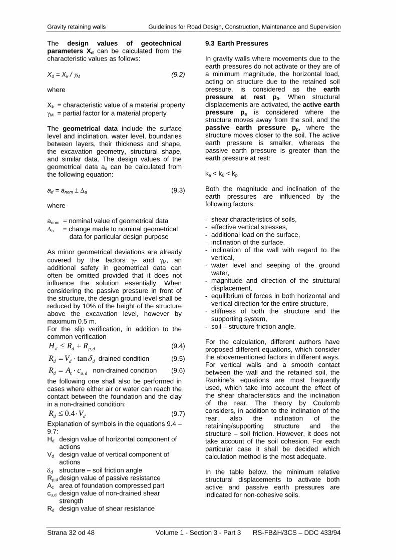
Gravity retaining walls Guidelines for Road Design, Construction, Maintenance and Supervision The design values of geotechnical parameters Xd can be calculated from the characteristic values as follows:
9.3 Earth Pressures
Strana 32 od 48 Volume 1 - Section 3 - Part 3 RS-FB&H/3CS – DDC 433/94
Xd = Xk / γM (9.2)
In gravity walls where movements due to the earth pressures do not activate or they are of a minimum magnitude, the horizontal load, acting on structure due to the retained soil pressure, is considered as the earth pressure at rest p0. When structural displacements are activated, the active earth pressure pa is considered where the structure moves away from the soil, and the passive earth pressure pp, where the structure moves closer to the soil. The active earth pressure is smaller, whereas the passive earth pressure is greater than the earth pressure at rest:
where Xk = characteristic value of a material property γM = partial factor for a material property The geometrical data include the surface level and inclination, water level, boundaries between layers, their thickness and shape, the excavation geometry, structural shape, and similar data. The design values of the geometrical data ad can be calculated from the following equation:
ka < k0 < kp
ad = anom ± Δa (9.3) Both the magnitude and inclination of the earth pressures are influenced by the following factors:
where
- shear characteristics of soils, anom = nominal value of geometrical data - effective vertical stresses, Δa = change made to nominal geometrical - additional load on the surface, data for particular design purpose - inclination of the surface, - inclination of the wall with regard to the
vertical, As minor geometrical deviations are already covered by the factors γF and γM, an additional safety in geometrical data can often be omitted provided that it does not influence the solution essentially. When considering the passive pressure in front of the structure, the design ground level shall be reduced by 10% of the height of the structure above the excavation level, however by maximum 0.5 m.
- water level and seeping of the ground water,
- magnitude and direction of the structural displacement,
- equilibrium of forces in both horizontal and vertical direction for the entire structure,
- stiffness of both the structure and the supporting system,
- soil – structure friction angle. For the slip verification, in addition to the common verification
dpdd RRH ,+≤ (9.4)
ddd VR δtan⋅= drained condition (9.5)
ducd cAR ,⋅= non-drained condition (9.6) the following one shall also be performed in cases where either air or water can reach the contact between the foundation and the clay in a non-drained condition:
dd VR ⋅≤ 4.0 (9.7)
For the calculation, different authors have proposed different equations, which consider the abovementioned factors in different ways. For vertical walls and a smooth contact between the wall and the retained soil, the Rankine’s equations are most frequently used, which take into account the effect of the shear characteristics and the inclination of the rear. The theory by Coulomb considers, in addition to the inclination of the rear, also the inclination of the retaining/supporting structure and the structure – soil friction. However, it does not take account of the soil cohesion. For each particular case it shall be decided which calculation method is the most adequate.
Explanation of symbols in the equations 9.4 – 9.7: Hd design value of horizontal component of actions Vd design value of vertical component of actions δd structure – soil friction angle In the table below, the minimum relative
structural displacements to activate both active and passive earth pressures are indicated for non-cohesive soils.
Rp,d design value of passive resistance Ac area of foundation compressed part cu,d design value of non-drained shear strength Rd design value of shear resistance

Guidelines for Road Design, Construction, Maintenance and Supervision Gravity retaining walls Table 9.6: Required minimum displacements to activate active and passive earth pressures
Active earth pressure Passive earth pressure Loose soils Dense soils Loose soils Dense soils Displacement type
va / h (%) va / h (%) vp / h (%) vp / h (%)
0.4 – 0.5 0.1 – 0.2 7 (1.5) – 25 (4) 5 (1.1) – 10 (2)
0.2 0.05 – 0.1 5 (0.9) – 10 (1.5) 3 (0.5) – 6 (1)
0.8 – 1.0 0.2 – 0.5 6 (1) – 15 (1.5) 5 (0.5) – 6 (1.3)
0.4 – 0.5 0.1 – 0.2
va = wall displacement to activate active earth pressures h = wall height
vp = wall displacement to activate passive earth pressures h = wall height
The values in parentheses for the passive earth pressure apply to relative displacements required to activate a half of the passive earth pressures. In case that the soils are located below the water level, the relative displacement for the passive resistance shall exceed the values, indicated in the table 9.6, by a factor of 1.5 – 2. The passive resistance in front of the gravity wall foundations shall be taken into consideration in the following cases only: - adequate structural displacements are
activated, - no material will be excavated, - in the entire service life, such soil
compaction and grade can be ensured, which has been taken into account by the design calculations,
- no loosening and washing away of soils, nor impairing of their properties due to ground water actions or climatic conditions will take place,
- no fissure between the foundation and the soil will occur due to the soil shrinkage.
9.3.1 Earth Pressure at Rest The earth pressure at rest p0 can be calculated from the vertical effective stresses σ’ using the following equation:
00 kp ⋅′= σ (9.8) For horizontal and normally consolidated ground the Jaky’s equation applies:
)( ϕsin10 −=k (9.9) For pre-consolidated ground the following equation is relevant:
)( OCRk ⋅−= ϕsin10 (9.10) where ϕ = shear angle of soil OCR = factor of pre-consolidation When the rear is inclined by the angle β to the horizontal, the coefficient of the earth pressure at rest k0,β (for the horizontal component) is calculated from the following equation:
)( ββ sin10,0 +⋅= kk (9.11) 9.3.2 Active and Passive Earth Pressure
by Rankine Rankine’s equations for both the active earth pressure pa in passive earth pressure pp are as follows:
( ) aa kckp ⋅⋅−⋅⋅′= 2cos0 βσ (9.12)
( ) pp kckp ⋅⋅+⋅⋅′= 2cos0 βσ (9.13)
RS-FB&H/3CS – DDC 433/94 Volume 1 - Section 3 - Part 3 Strana 33 od 48
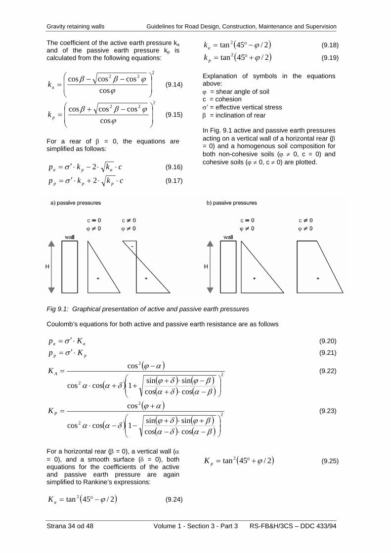
Gravity retaining walls Guidelines for Road Design, Construction, Maintenance and Supervision The coefficient of the active earth pressure ka and of the passive earth pressure kp is calculated from the following equations:
222
coscoscoscos
⎟⎟
⎠
⎞
⎜⎜
⎝
⎛ −−=
ϕϕββ
ak (9.14)
222
coscoscoscos
⎟⎟
⎠
⎞
⎜⎜
⎝
⎛ −+=
ϕϕββ
pk (9.15)
For a rear of β = 0, the equations are simplified as follows:
ckkp apa ⋅⋅−⋅′= 2σ (9.16)
ckkp ppp ⋅⋅+⋅′= 2σ (9.17)
( )2/45tan 2 ϕ−°=ak (9.18)
( )2/45tan2 ϕ+°=pk (9.19) Explanation of symbols in the equations above: ϕ = shear angle of soil c = cohesion σ’ = effective vertical stress β = inclination of rear In Fig. 9.1 active and passive earth pressures acting on a vertical wall of a horizontal rear (β = 0) and a homogenous soil composition for both non-cohesive soils (ϕ ≠ 0, c = 0) and cohesive soils (ϕ ≠ 0, c ≠ 0) are plotted.
Fig 9.1: Graphical presentation of active and passive earth pressures Coulomb’s equations for both active and passive earth resistance are as follows
aa Kp ⋅′= σ (9.20)
pp Kp ⋅′= σ (9.21)
)(
)( )( )()( )(
2
2
2
coscossinsin1coscos
cos
⎜⎜⎝
⎛⎟⎟⎠
⎞
−⋅+−⋅+
++⋅
−=
βαδαβϕδϕδαα
αϕAK (9.22)
)(
)( )( )()( )(
2
2
2
coscossinsin1coscos
cos
⎜⎜⎝
⎛⎟⎟⎠
⎞
−⋅−+⋅+
−−⋅
+=
βαδαβϕδϕδαα
αϕPK (9.23)
For a horizontal rear (β = 0), a vertical wall (α = 0), and a smooth surface (δ = 0), both equations for the coefficients of the active and passive earth pressure are again simplified to Rankine’s expressions:
( 2/45tan 2 ϕ−°=aK
( )2/45tan 2 ϕ+°=pK (9.25)
) (9.24)
Strana 34 od 48 Volume 1 - Section 3 - Part 3 RS-FB&H/3CS – DDC 433/94

Guidelines for Road Design, Construction, Maintenance and Supervision Gravity retaining walls Explanation of symbols in the equations of the theory by Coulomb: σ’ = effective vertical stress ϕ = shear angle of soil β = inclination of rear α = inclination of wall δ = wall – soil friction angle In Fig. 9.2 signs for surface inclination are indicated. In Fig. 9.3 the influence of the wall inclination and of the structure – soil friction on the direction of the resultant of earth pressures in presented.
Fig.9.2: Consideration of both rear and wall inclination
Fig.9.3: Example of influence of a wall on the inclination of resultants of earth pressures In Fig. 9.4 three geometrically different gravity walls are shown. In addition, the influence of the shape on the principal loads, i.e. dead weight of the wall (Gwall), weight of the earth above the toe and cantilever (Gearth), active earth pressure (Ea), and passive earth pressure (Ep) is indicated. The passive earth pressure is shown on the first example only. In the wall with a cantilever in point T, the effective vertical stresses drop to σ’v = 0 kPa, thus the active earth pressures are nil at that depth. At the height h1, assuming a linear function, they reach the basic line of the active earth pressures as shown in Fig. 9.4 c. The height h1 depends on the cantilever length lc and the shear angle of soil ϕ: h1 = lc ⋅ tan(45°+ ϕ/2) (9.26)
Fig.9.4: Loads acting on gravity walls
RS-FB&H/3CS – DDC 433/94 Volume 1 - Section 3 - Part 3 Strana 35 od 48

Gravity retaining walls Guidelines for Road Design, Construction, Maintenance and Supervision 10 GRAVITY RETAINING AND
SUPPORTING WALL DEWATERING AND BACKFILLING
The following four themes are discussed in the present chapter: - rear water drainage - surface water drainage - backfilling on wall rear side - backfilling on wall front side, protection 10.1 Rear Water Drainage 10.1.1 General In the ground behind a retaining/supporting wall, ground water, seepage rock water, and accumulated water can occur. Where supporting walls are executed in water, effects of movement of the water level in the bed and, as a consequence, behind the wall are essential. If the effects of the rear waters are not prevented, additional water pressures behind the wall occur, and the shear strength of the backfill wedge can be reduced at the same time. For an effective prevention of water pressures it is mandatory to foresee rear water drainage when executing gravity walls. A drainage system design, being a condition to carry through an effective draining of the wall rear, depends on the hydro-geological and soil mechanical ground properties, the shape of grading curve, soil permeability, chemical composition, and hazard of internal erosion in the rear backfill and solid ground. Taking account of actions of rear water current forces, inclined position of the rear drainage would be the best. However, in most cases, this is unfeasible. To achieve a correct position of the drainage layer it is necessary to take account of the fact that the active earth pressure is only increased in cases where a hydrostatic height of the ground water permanently takes place (stationary condition). The pressure on a gravity wall increases in cases where, due to an extensive inflow particularly of precipitation waters, the drainage layer conveys the water away slower than the latter is flowing into.
Fig.10.1: Possible alternatives of locating the
drainage layer at the gravity wall rear (1 cohesive retained soil – solid or backfilled, 2 impermeable foundation soil) 10.1.2 Methods of Drainage Layer
Execution A foreseen drainage system shall ensure such a sufficient leading away of rear waters as to prevent the structure to be exposed to additional pressure due to accumulation of the rear water. A drainage system is composed of the following: - a drainage or filter layer, - a continuous drainage pipe running along
the drainage layer and leading water away to a suitable sewer.
When constructing drainage systems behind gravity walls it is essential to distinguish: - a supporting wall, at the rear of which a
backfill or a fill will be executed, or - a retaining wall in cuts and fills with a
stable solid rear. Taking into consideration that drainages are rarely or even never maintained, which is often result of their inaccessibility, it is required, in addition to a correct design of common filtration, to foresee the
Strana 36 od 48 Volume 1 - Section 3 - Part 3 RS-FB&H/3CS – DDC 433/94

Guidelines for Road Design, Construction, Maintenance and Supervision Gravity retaining walls consequences of a reduced effect of filtration due to deposition of mineral substances in the filtration water. In case that a drainage layer is made of a non-cohesive loose material, it shall comply with the following requirements: - it shall be stable to filtering, - it shall be water permeable such as gravel
of suitably graded grain size, - in the absence of a special capacity
calculation, the drainage layer thickness shall amount to at least 40 – 80 cm.
Where a drainage layer is carried out in combination with a filter geo-textiles, the latter shall be placed directly onto the slope of the excavated solid ground, whereas the intermediate space shall be filled up with a coarse-grained stone material, which enables the entire seepage water to reach a drainage pipe at the bottom of the filter layer, from where it flows away to a suitable sewer. The filter position selected in such a way prevents internal erosion in a solid ground. A deficiency of geo-textiles layers is in its sensitivity to mineral solutions in the seepage water causing its stoppage. In areas of high concentration of mineral substances geo-textiles shall not be applied. An alternative solution, in particular for vertical drainage layers, is the drain cement concrete. It is favourable for its simple casting, as it does not require any compaction, which is of an extreme importance to walls placed into a rocky rear with a limited rear excavation. In addition, an adequate strength is ensured as well.
Fig.10.2: Execution of drainage by means of a
packed rockfill or gravel balls (1 excavation, 3 filling concrete, 4 packed rockfill or gravel balls, 5 drainage pipe of dmin = 20 cm)
The following shall be specified: - thickness e of the filter layer - filter material Application: for retaining/supporting walls in mountainous areas and where a coarse-grained rear backfilling material is used.
Fig.10.3: Execution of drainage by means of a single filter (1 excavation, 2 backfill, 3 filling concrete, 5 drainage pipe of dmin = 20 cm, 6 filter) The following shall be specified:
- thickness e of the filter layer - filter material
Application: in case of sandy and gravely backfilling material
Fig.10.4: Execution of drainage by means of a
double filter (1 excavation, 2 backfill, 3 filling concrete, 5 drainage pipe of dmin = 20 cm,7 standard filter I, 8 standard filter II)
RS-FB&H/3CS – DDC 433/94 Volume 1 - Section 3 - Part 3 Strana 37 od 48

Gravity retaining walls Guidelines for Road Design, Construction, Maintenance and Supervision The following shall be specified: - thickness e1 and e2 of the filter layers - filter material Application: in case of fine-grained clayey ground
Fig.10.5: Execution of drainage by means of
drain cement concrete (1 excavation, 3 filling concrete, 5 drainage pipe of dmin = 20 cm, 9 drain cement concrete, 10 gravel balls 30-50 mm)
The following shall be specified: - thickness e of the filter layer - grain size and cement portion Application: in all the cases where the filter shall prove certain strength When selecting filter materials, one shall take account of the fact that a filter must perform both hydraulic and mechanical function. In addition, a filter shall prevent internal erosion of loose stone mineral grains from the soil adjoining the filter, and, at the same time, ensure sufficient water permeability. Materials suitable to execute a filter can be classified in the following groups: - loose stone mineral grains of a single grain
size or a well graded grain size (sands, gravels);
- hydraulically or by means of bitumen conglomerated materials (filter or drain cement concrete); the concrete aggregate is of a single grain size, the filter is carried out either monolithically or at a prefabrication plant;
- filter geo-textiles.
A filter layer is considered as effective when the water flowing through a layer of non-cohesive stone grains of increasing permeability is pure and of sufficient quantity. In Fig. 10.6 grading curves for individual soil types are indicated; on the basis of those curves, a suitable filter type shall be selected. - soil for which the grading curve in the zone
A is relevant are not endangered or insignificantly endangered in view of the internal erosion; in this case, the function of the filter is rather mechanical than hydraulic;
- silts, sandy silts and fine sands (zone B) represent a soil of a maximum proneness to the internal erosion; particularly single-grained soils are jeopardized;
- soils where the grading curve lies in the zone C do not, as a rule, require a filter layer, but only a suitable dimension of the openings in the drainage pipe wall.
Fig.10.6: Zones of grading curves for soil
types A, B, and C 10.1.3 Evacuation of Water From the
Drainage Layer To evacuate the water flowing together through the filter layer, longitudinal drainage pipes shall be installed at the lowest point. Drainage pipes can be perforated concrete pipes, pipes of filter cement concrete or plastic pipes (usually PVC pipes). A third to a half of the upper circumference of a pipe can be perforated. The minimum pipe diameter shall be 200 mm. If there is a danger of formation of calcareous layers at the pipe interior, the diameter shall be increased. PVC pipes are more suitable from the point of view of preventing calcareous layers.The minimum longitudinal fall of a drainage pipe amounts to 1%. To ensure a proper keeping of a drainage pipe run-through capacity, inspection shafts shall be foreseen at spacing of 50 – 70 m, depending on the topography. In dependence on the shaft depth, the shaft diameter shall not be less than 80 cm.
Strana 38 od 48 Volume 1 - Section 3 - Part 3 RS-FB&H/3CS – DDC 433/94

Guidelines for Road Design, Construction, Maintenance and Supervision Gravity retaining walls
Fig.10.7: Longitudinal profile of drainage of the
wall rear (1 perforated concrete pipe, 2 concrete gutter or channel, 3 inspection shaft, 4 concrete pipe of dmin = 30 cm, 5 ground surface, 6 connection to sewer)
Drainage pipes shall be placed into an underlay concrete bed, which, in its cross section, must reach the excavated slope by the entire filter width. By suitable concrete underlay fall it can be ensured that all the collected water flows away into the drainage pipe. A perforated pipe is encompassed by concrete underlay up to the height of the perforation in the pipe wall. The concrete bed thickness depends on the ground conditions. However, it shall not be less than 20 cm. The outlets in the wall (weeping drainages) are the sole drainage elements to be only used for contact concreting of slopes of low water bearing capacity. All the abovementioned examples are used in cases where the bottom of a gravity wall foundation is situated in an impermeable ground, which prevents the rear water to flow away through the foundation soil. Where the foundation bottom is located in a permeable soil and the backfilling of the gravity wall rear is carried out with an impermeable material, dewatering of the rear can be executed without any drainage pipe behind the wall. In such a case it is sufficient to create a direct connection between the filter layer and the permeable solid ground. Where the rear backfilling is performed using a permeable material, the filter layer behind the wall need not be foreseen, whilst a drainage pipe at the wall bottom is indispensable in case of an impermeable foundation soil only.
Gravity walls along water streams are subject to the water level alterations. When the water level raises at the wall front the same will occur at the rear as well. For an effective water level regulation on both sides of the wall an appropriate network of weeping drainages in the gravity wall and a drain capacity of the rear backfill are required. For the rear, the abovementioned instructions for the drainage apply, taking account of the fact that no longitudinal drainage pipe is placed. However, a suitable network of weeping drainages in the wall is mandatory (weeping drainages spaced at 2.0 m maximum, diameter 120 mm minimum). The backfill around the weeping drainages shall be carried through with stone balls. The cantilever shall be drained by means of a drainage pipe placed at the contact between the wall and the cantilever. The seepage water flows to the drainage pipe via cantilever, which shall be executed at an inclination of 4% towards the wall. The drainage pipe outlet shall be connected with the remaining rear water drainage system. 10.2 Surface Water Drainage By draining the surface water from the slopes behind a gravity wall, seeping of such water into the drainage layer is prevented, thus the latter is not additionally loaded. Surface water can be captured by means of common drainage elements such as gutters, channels or paved ditches. Then, the water is canalised via suitable collecting shafts with sand captures to a separate dewatering system. The sand captures shall be so executed as to be well accessible and simple to maintenance. It is recommended to plant shrubbery at the crown rear, as those plants are intensive water consumers.
Fig.10.8: Drainage without a gutter – for
ground inclinations up to 5% with a minor water inflow (1 gravel balls of 30-50 mm, 2 filter, 3 grassed rear surface)
RS-FB&H/3CS – DDC 433/94 Volume 1 - Section 3 - Part 3 Strana 39 od 48

Gravity retaining walls Guidelines for Road Design, Construction, Maintenance and Supervision
Fig.10.9: Drainage by means of a grassy ditch
– for ground inclinations between 5% and 12% with a medium water inflow (2 filter, 3 grassed rear surface)
Fig.10.10: Drainage by means of a gutter – for ground inclinations between 5% and 12% with a major water inflow (2 filter, 3 grassed rear surface,
4 gutter)
Fig.10.11: Drainage by means of a channel –
for ground inclinations greater than 12% with a major water inflow (2 filter, 3 grassed rear surface, 5 channel element)
At the gravity wall ends, the elements for draining the surface rear water shall be adequately terminated and connected with the road drainage system. The execution shall be such as to ensure protection from erosion of the free slope part.
10.3 Backfilling on Wall Rear Side A great portion of damages to gravity walls results from an unprofessional backfilling. Usually, the backfill is excessively compacted next to behind the wall. For retaining walls the following procedure is recommended: - the material shall be applied in layers of 30
cm in thickness maximum, and compacted by means of light compacting devices;
- the compaction shall commence not nearer than 1 m from the rear wall and continue away from the wall;
- the upper meter of the backfill shall be compacted up to the wall;
- a constant thickness of a single or double filter layer shall be ensured by pulling boards or steel plates;
- the upper surface of the backfill shall be covered by a soil layer of low permeability.
Fig.10.12: Detail of backfilling of a gravity
retaining wall (1 filter, 2 un- compacted zone of approx. 1.0 m in width, 3 thoroughly compacted zone, 4 soil of low permeability)
For supporting walls the rear backfill shall be well compacted to achieve the required bearing capacity and smallest possible settlements. The higher the compaction, the lower the permeability. As a rule, the backfill volume is much bigger in supporting walls as in retaining walls.
Strana 40 od 48 Volume 1 - Section 3 - Part 3 RS-FB&H/3CS – DDC 433/94

Guidelines for Road Design, Construction, Maintenance and Supervision Gravity retaining walls The rear backfill connection can be executed in either of the following ways: - A supporting structure is completely
constructed prior to the fill or backfill execution; the fill or backfill construction is carried through later in layers in the entire fill/backfill width, width a direct connection to the wall; the layers located close to the rear wall are executed in a half thickness and by means of lighter compaction devices. When the fill is constructed of a cohesive soil, an approximately 1 m wide zone of suitable filter material shall be executed at the wall. That filter material enables the rear water drainage (Fig. 10.13). When the fill is constructed of a non-cohesive, well impermeable material, no filter layer (6) is necessary at the rear wall. Only a drainage pipe stable to filtering shall be built-in for draining the seepage water (Fig. 10.14).
Fig.10.13: Connection of a fill made of cohesive material to the supporting wall (1 excavation, 2 backfill of cohesive material, 3 cohesive impermeable material, 5 drainage pipe, 6 filter) - A supporting structure is shifted away from
the natural rear or fill. In this case, the rear backfilling is executed in a shape of a backfill wedge. When the backfill wedge consists of a permeable material, a filter is required in special cases only, i.e. at the boundary between the solid ground or constructed fill and the backfill wedge made of a non-cohesive and sufficiently water-permeable soil (Fig. 10.15). When the backfill wedge is made of a cohesive soil, a drainage layer (filter) shall be executed at the retaining wall (Fig. 10.16).
Fig.10.14: Connection of a fill made of non- cohesive material to the supporting wall (1 excavation, 2 backfill of non-cohesive material, 3 cohesive impermeable material, 5 drainage pipe)
Fig.10.15: Backfill wedge of non-cohesive soil (1 excavation, 2 backfill of non-cohesive material, 3 cohesive impermeable material, 5 drainage pipe, 6 filter - as necessary)
Fig.10.16: Backfill wedge of cohesive soil and single filter (1 excavation, 2 backfill of cohesive material, 3 cohesive impermeable material, 5 drainage pipe, 6 filter)
RS-FB&H/3CS – DDC 433/94 Volume 1 - Section 3 - Part 3 Strana 41 od 48
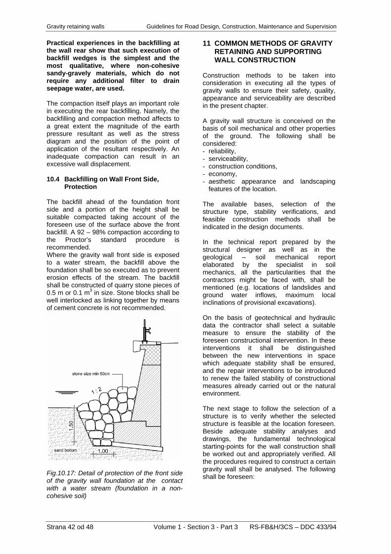
Gravity retaining walls Guidelines for Road Design, Construction, Maintenance and Supervision Practical experiences in the backfilling at the wall rear show that such execution of backfill wedges is the simplest and the most qualitative, where non-cohesive sandy-gravely materials, which do not require any additional filter to drain seepage water, are used. The compaction itself plays an important role in executing the rear backfilling. Namely, the backfilling and compaction method affects to a great extent the magnitude of the earth pressure resultant as well as the stress diagram and the position of the point of application of the resultant respectively. An inadequate compaction can result in an excessive wall displacement. 10.4 Backfilling on Wall Front Side,
Protection The backfill ahead of the foundation front side and a portion of the height shall be suitable compacted taking account of the foreseen use of the surface above the front backfill. A 92 – 98% compaction according to the Proctor’s standard procedure is recommended. Where the gravity wall front side is exposed to a water stream, the backfill above the foundation shall be so executed as to prevent erosion effects of the stream. The backfill shall be constructed of quarry stone pieces of 0.5 m or 0.1 m3 in size. Stone blocks shall be well interlocked as linking together by means of cement concrete is not recommended.
Fig.10.17: Detail of protection of the front side of the gravity wall foundation at the contact with a water stream (foundation in a non-cohesive soil)
11 COMMON METHODS OF GRAVITY
RETAINING AND SUPPORTING WALL CONSTRUCTION
Construction methods to be taken into consideration in executing all the types of gravity walls to ensure their safety, quality, appearance and serviceability are described in the present chapter. A gravity wall structure is conceived on the basis of soil mechanical and other properties of the ground. The following shall be considered: - reliability, - serviceability, - construction conditions, - economy, - aesthetic appearance and landscaping
features of the location. The available bases, selection of the structure type, stability verifications, and feasible construction methods shall be indicated in the design documents. In the technical report prepared by the structural designer as well as in the geological – soil mechanical report elaborated by the specialist in soil mechanics, all the particularities that the contractors might be faced with, shall be mentioned (e.g. locations of landslides and ground water inflows, maximum local inclinations of provisional excavations). On the basis of geotechnical and hydraulic data the contractor shall select a suitable measure to ensure the stability of the foreseen constructional intervention. In these interventions it shall be distinguished between the new interventions in space which adequate stability shall be ensured, and the repair interventions to be introduced to renew the failed stability of constructional measures already carried out or the natural environment. The next stage to follow the selection of a structure is to verify whether the selected structure is feasible at the location foreseen. Beside adequate stability analyses and drawings, the fundamental technological starting-points for the wall construction shall be worked out and appropriately verified. All the procedures required to construct a certain gravity wall shall be analysed. The following shall be foreseen:
Strana 42 od 48 Volume 1 - Section 3 - Part 3 RS-FB&H/3CS – DDC 433/94

Guidelines for Road Design, Construction, Maintenance and Supervision Gravity retaining walls
RS-FB&H/3CS – DDC 433/94 Volume 1 - Section 3 - Part 3 Strana 43 od 48
- possible access roads, - working fields for the construction, - method of earth works including suitable
safeguarding, - protection from factors which might impede
the construction (e.g. water streams, rear water),
- traffic and functioning of other infrastructural flows shall be ensured,
- sequence of construction stages in view of determining the point of commencement and the direction of the work progress,
- mandatory technologies to be considered in the individual construction stages,
- definition of adequate details and solutions, - requirements with reference to a
simultaneous quality assurance of both materials and procedures,
- requirements with regard to the survey control
- feasibility of subsequent maintenance. The gravity wall construction is composed of several stages, which are interconnected and shall be properly sequenced. Those stages shall be harmonized with eventual other structures in connection with which the subject gravity wall is executed. In the design special attention shall be paid to the individual safety of the subject and adjacent structures, as well as to the safety and stability of the entire area in connection with the feasibility to implement any individual stage. Due to the specificity of the construction, the contractor shall elaborate a method statement prior to commencement of the works. This document shall ensure the designed shape, quality, and durability of the structures, taking account of all the requirements with reference to assuring health and safety at work. Any eventual deviations from the design solutions are only admissible upon a written consent by both client and responsible design engineer. The access road to the working fields shall enable a reliable and safe transportation of both labour and material. The access road course and compaction shall be such as to prevent any impact on the stability of the cut and fill slopes of the road. The road width shall be adjusted to the ground conditions and types of vehicles or mechanization, yet it shall not be less than 3.0 m.
The working field shall be sufficiently wide to enable a quality and safe work. When planning the working field width, the required width to place, support and protect the formwork elements, to erect working scaffolds, and to enable the use of mechanization shall be considered. The dewatering of both access roads and working fields shall be settled immediately as to prevent instabilities on the site and damages to the roads and working fields. Design solutions shall be taken into consideration when planning excavations of gravity wall foundations. A construction pit opening may be carried through at a length not greater than that of one wall segment or to a maximum extent admitted by the design. The rear excavation shall be executed to such an extent as to ensure an adequate stability of the excavated slope. Where for justified reasons the inclination of the excavated slope is greater than that specified by the design, suitable protection to ensure at least equal stability shall be provided. The responsible designer shall approve any modification. Where a gravity wall is founded in water, an adequate protection from the water flow shall be foreseen. Such a protection shall ensure safety of the working field and prevent harmful impacts of the water stream on the wall structural elements. Prior to place the concrete underlay, the responsible specialist in soil mechanics shall take over the construction pit. In case that any deviations from the design soil properties are established, appropriate measures shall be directed (e.g. replacement of soil of low bearing capacity with a suitable material or concrete underlay, other mechanical or chemical methods for soil improvement). Both the contractor and supervisor are responsible for a geometrical shape of the foundation. Where a gravity wall is founded in a solid ground, the depth of the cut into the rock base shall be adjusted to the rock grade, yet it shall not be less than 0.50 m. Prior to casting the concrete, the rock surface shall be thoroughly cleaned as to achieve a perfect adhesion of the foundation to the rock. Temporary slopes in the retaining/supporting wall construction, particularly in pre-consolidated saturated materials, which absorb the precipitation water, lose an essential portion of their strength and can become unstable; therefore, they shall be protected by means of an impermeable foil.
Gravity retaining walls Guidelines for Road Design, Construction, Maintenance and Supervision
Strana 44 od 48 Volume 1 - Section 3 - Part 3 RS-FB&H/3CS – DDC 433/94
In case of a potential local instability, which occurs particularly in soft slate stones, slopes shall be protected by shot cement concrete and passive anchors. Design instructions dealing with the formwork elements for the gravity wall construction shall be considered. The type and quality of those elements depends on the wall side (front or rear), and an eventual finishing of exposed surfaces. The steel reinforcement of reinforced concrete gravity walls shall be placed in compliance with the design. Special attention shall be paid to the concrete cover, which thickness shall amount to at least 5 cm for surfaces buried in ground and 4.5 cm for non-buried surfaces respectively. Adequate spacers shall be introduced to ensure the prescribed concrete covers. The spacers shall be made of materials having the same characteristics as the concrete. Concreting of gravity walls may commence after the steel reinforcement has been taken over by the supervisor. The number of construction joints shall be as small as possible. Where such joints are inevitable due to some technological reasons or the height, they shall be carried out waterproof, following the requirements in view of the water-tightness of the entire structure. Contact joints between individual wall segments shall be executed in accordance with the DG 1.2.9. Special attention shall be paid to the cases where a non-uniform bearing capacity of the foundation soil takes place at individual segments. In such cases, grooves shall be foreseen to prevent displacements between individual segments. Where gravity supporting walls are constructed, they shall be executed in segments up to the crown height. Finally, an edge beam including a safety barrier is constructed. Rear backfilling is carried out in compliance with the prescribed procedures. Backfilling and its compaction can only be performed after the gravity wall concrete has attained the specified strength. All drainage elements on the gravity wall rear side shall be executed in accordance with the prescribed methods. They may only be backfilled after the responsible supervisor has approved their proper performance.
12 SUPERVISION OF
CONSTRUCTION, QUALITY ASSURANCE, AND MAINTENANCE OF GRAVITY RETAINING AND SUPPORTING WALLS
12.1 Supervision and Quality Assurance
of Gravity Retaining and Supporting Wall Construction
To ensure construction of a quality and safe gravity wall, an adequate supervision of construction is required in addition to a professional and capable contractor. A cooperation of designer, contractor, and supervisor is required to ensure that the construction is carried out in a correct sequence of working operations being a warrantor for an adequate quality and fulfilment of the construction time schedule. The following shall be supervised: - whether a retaining/supporting wall is
constructed in compliance with the verified and revised design documents;
- whether all the modifications and supplements occurring during construction are entered in the project execution design, and whether both the client and the designer have agreed with those modifications;
- whether the quality of materials and products, installations, technological devices and equipment as well as the adopted methods have been approved by suitable documents;
- whether the construction is carried through in accordance with the agreed time schedule.
The responsible supervisor shall enter his findings in the construction logbook daily. A suitable staking out of gravity retaining wall characteristic points to be carried out by a responsible surveyor is a base for a proper position of the wall in the space and for its design dimensions. The staking out shall be handed over by a protocol to be approved by the surveyor, contractor’s representative, and supervising engineer. Within the scope of the construction pit taking over to be performed by both the supervising engineer for construction works and the responsible soil mechanics expert it is necessary to check eventual deviations from the design. When the deviations are such as to require some modifications, the latter shall be worked out or approved by the responsible designer on the basis of information submitted by both the soil mechanics expert and contractor.

Guidelines for Road Design, Construction, Maintenance and Supervision Gravity retaining walls
RS-FB&H/3CS – DDC 433/94 Volume 1 - Section 3 - Part 3 Strana 45 od 48
Gravity wall construction shall be supervised in compliance with the relevant legislation. It is recommended to engage, in addition to the supervisor and soil mechanics expert, also the design engineer to perform the supervision from his point of view (supervision by the designer). The duty of the supervisor is to check the following: - placing the formwork, - formwork material, - placing the steel reinforcement, - concrete cover to reinforcement, - construction and expansion joints, - provisional measures during construction in
view of ensuring health and safety at work, - placing dewatering elements, - placing other elements that are
inaccessible/invisible after the construction is completed.
Prior to backfilling, the supervisor shall take over all the elements to be backfilled. A suitable record in the construction logbook is mandatory. During the construction, record of any eventual modifications and supplements of the design documents shall be kept regularly. The design bureau engaged to work out the as-built design shall be immediately informed about all the design modifications or supplements. Therefore it is recommended that such a design bureau is selected not later than upon the commencement of the construction works. Within the scope of the taking over of a gravity wall, the compliance of the geometry and material quality with the design requirements shall be verified. It is obligatory to establish whether the structure has been built in such a way as to ensure a safe exploitation in the entire design service life, and its conformity with the building permit issued. 12.2 Gravity Retaining and Supporting
Wall Maintenance Beside a quality execution, maintenance is extremely important to a safe and durable construction. A base for a proper maintenance of a gravity wall is an adequate professional qualification of the maintainer as well as a maintenance plan comprising all the structural particularities, which the maintainer shall pay attention to.
To ensure an effective maintenance, the responsible maintainer shall, in addition to the general provisions and instructions, consider individual structural peculiarities as well. The maintenance and operation plan, which shall be worked out by the contractor, is a systematically organized document comprising photos, drawings, and texts, indicating proper measures for the use and maintenance of a gravity wall, auxiliary structures, and built-in installations. In the maintenance plan all the characteristic structural dimensions, drainage system, as well as description and position of eventually built-in installations shall be presented. The information shall be indicated in a form of appropriate drawings and additional textual explanations. Where in a certain structure special attention is to be paid to some elements or details, this shall be specially mentioned. A zero levelling of benchmarks to be built-in by the contractor is a constituent part of the maintenance plan as well. The following essential works shall be carried out within the scope of the gravity wall maintenance: - regular measurements of the benchmarks
and comparing the results with those of the zero measurement; in case that the measured displacements exceed 5.0 m, measurements shall be performed more frequently;
- cleansing the elements to drain both rear and surface water; drainage systems, sewers, and surface drains such as ditches, gutters and channels shall be free of all the dirt and shall ensure an unimpeded flow through capacity; special attention shall be paid to those elements shall be paid in autumn and spring;
- cleansing of the structure at the end of the winter period;
- checking eventual structural cracks, which might be a consequence of exceptional events (natural disasters such as earthquakes, floods, landslips, traffic accidents, etc., or of eventual undiscovered deficiencies or aging of the structure.
By implementing the superintendence, a level of the regular maintenance can be determined, and deficiencies that might cause major damage can be established and made good.

Gravity retaining walls Guidelines for Road Design, Construction, Maintenance and Supervision
Strana 46 od 48 Volume 1 - Section 3 - Part 3 RS-FB&H/3CS – DDC 433/94
The superintendence is composed of the following activities: - carrying out inspections, - preparation of reports, - planning maintenance and repair works, - controlling quality of maintenance and
repair works. The inspections are divided by time and function in the following ones: - technical inspection (upon bridge handing
over), - routine inspections (at least once a month), - regular inspections every 2 years, - main inspections every 6 years and prior to
expiry of the guarantee period, - extraordinary inspections (immediately
after exceptional events), - detailed inspections (with a special
intention). In the guarantee period, the inspections, with the exception of the routine ones, are carried through with the knowledge of the contractor liable to the guarantee. The bridge owner/maintainer is obliged to inform the contractor of the date of inspection. In the guarantee period, the owner/maintainer must also organise an extraordinary inspection in case of an exceptional event. 12.2.1 Technical Inspection This is the initial technical inspection upon the project handing over, also called zero-inspection. It shall be carried out in accordance with the current Construction Law by the authority who has issued the building permit. By the technical inspection it shall be established whether: - the gravity wall has been constructed in
compliance with the building permit; - it is clear from the evidence for the
structural reliability that the gravity wall has been executed in accordance with the construction regulations being mandatory for such structures, and with the conditions specified for the construction;
- it is evident from the evidence for the structural reliability that the prescribed provisions to prevent or minimize the impacts by the gravity wall itself have been taken into consideration;
- the installations, technological devices, and equipment are properly built-in, and whether they fulfil the prescribed parameters, taking account of the technology, health, and safety at work, of fire protection, and of environment protection;
- a suitable proof of the structural reliability in
compliance with the Construction Law exists;
- the maintenance and operation plan has been worked out in compliance with the Construction Law;
- a surveying drawing of the new ground condition including new structures has been elaborated in accordance with the geodesic regulations.
Both the zero levelling and the protocol of the measurement of reference points (benchmarks) shall be attached to the maintenance plan. 12.2.2 Routine Inspection Routine inspections are carried out by road inspectors at least once a month. Intention: To find out and make good particularly those deficiencies that might jeopardize the traffic safety. Extent and method: Visual establishing of deficiencies on the furniture (safety barrier, drainage, eventual corrosion) as well as making good minor defects, particularly in view of cleaning. Documents: A record of inspections performed shall be kept in the gravity wall maintenance book. When a major defect is discovered, the inspector is obliged to inform the road maintainer in writing. The inspection shall be carried out by the road inspector being supplementary schooled in this domain. 12.2.3 Regular Inspection The first regular inspection shall be carried out one year after the technical taking over. Other regular inspections are performed every two years, unless a main inspection coincides with the regular one. Intention: To check all the elements of the furniture and the load bearing system, which are accessible without any special devices. Beside phenomena, that threaten the traffic safety, damages and adverse features on the gravity wall, which could jeopardize the structural safety, serviceability and durability, shall be found out.
Guidelines for Road Design, Construction, Maintenance and Supervision Gravity retaining walls
RS-FB&H/3CS – DDC 433/94 Volume 1 - Section 3 - Part 3 Strana 47 od 48
Extent: - on the entire gravity wall, all the changes
that have occurred from the last regular inspection shall be established;
- condition of the gravity wall and its individual elements shall be assessed, as well as a deviation from the original quality shall be found out;
- eventual major deformations of the gravity wall shall be measured;
- levelling of reference points (benchmarks) shall be carried out, and the results shall be recorded in an adequate form;
- eventual measures for additional investigations shall be proposed;
- maintenance provisions shall be suggested.
Method: The inspection works shall be carried through visually or by means of simple investigations (percussion, sclerometry, levelling, etc.). Measuring devices: The concrete quality shall be checked by means of sclerometers. Displacements of benchmarks shall be measured with geodesic instruments, adopting methods, which ensure an accuracy of + 1 mm. Documents: It is mandatory to keep an inspection record. General data as well as the condition of the gravity wall, its bearing elements, and its furniture shall be recorded, and appropriate measures shall be foreseen. A standard record can be used. Performer of the inspection: A crew under the lead of an expert, i.e. civil engineer having passed a professional exam and being adequately experienced. In the guarantee period, a representative of the contractor, who is liable to the guarantee, shall attend the inspection. 12.2.4 Main Inspection Main inspections are carried through every six years and upon expiration of the liability period. Intention: The goals and content of main inspections are the same as it applies for regular inspections. However, a main inspection shall also cover locations of an insufficient accessibility or covered places, such as lower side of the deck, piers, bearings, etc. Suitable devices (standing or suspended scaffold, special vehicle) enabling access shall be
employed. Uncovering of backfilled surfaces shall only be carried out in case of suspicion of damages, which can be indicated by soaking, deformations, cracks or similar. During each main inspection, measurements of benchmarks shall be performed, which must be entered into a suitable form. Performer of the inspection: A crew under the lead of an expert, i.e. civil engineer having passed a professional exam and being specially qualified for inspection of gravity walls and assessment of their condition. As circumstances require, a professional institution can be engaged to perform special measurements and investigations. 12.2.5 Extraordinary Inspection Extraordinary inspections shall be carried out during or after exceptional events such as: - earthquake, heavy rainfall, flood, landslide,
exceptional temperatures, fire in close vicinity;
- heavy traffic accidents and impacts of vehicles on the gravity wall;
- where a displacement of benchmarks greater than 5.0 mm is established during a regular or main
- inspection, the measurement frequency shall be increased to six, three or even one month,
- depending on the magnitude of the displacement increments.
Both extent and goal of the inspection depend on the type and extent of damages or on the reason of the inspection. 12.2.6 Detailed Inspection A detailed inspection serves as a base to assess the actual quality and safety of the entire structure or as a base to carry through a diagnosis and define the rehabilitation method. A detailed inspection shall be executed in the following cases: - if the quality, bearing capacity or safety are
doubtable; - in case of increase of loading or in when
heavy transports are foreseen; - if the results of regular or main inspections
impose certain rehabilitation measures; - in case of disputes, litigations or similar. The content and extent of a detailed inspection depend on the motives for such an inspection. Beside visual inspection, the structure shall be tested statically and dynamically. In addition, characteristic structural elements and their materials shall be investigated as well.

Gravity retaining walls Guidelines for Road Design, Construction, Maintenance and Supervision
Strana 48 od 48 Volume 1 - Section 3 - Part 3 RS-FB&H/3CS – DDC 433/94
Detailed inspections are performed by professional institutions, having at disposal adequate equipment and experienced staff being able to execute the investigations required and to interpret the results obtained. The report shall include the results of all the measurements carried out, as well as appropriate decisions foreseen. 12.3 Maintenance Works Due to their substantial loading with earth pressure, traffic action, erosion phenomena and road maintenance measures (de-icing salts), gravity walls are classified in the category of highly loaded structures. A reduction of actions of those factors is of a great importance to the gravity wall service life. Beside cleansing of the gravity wall and its furniture as well as replacement of wearing parts, all other works not intervening in the structure also belong to the maintenance works. The extent of the required maintenance works, except regular cleansing, is determined by the conclusions of the abovementioned inspections. A maintenance book shall be kept where all the events that have happened on the gravity wall (such as maintenance works, inspections, exceptional heavy transports, etc.) are recorded. The maintenance book shall be accessible to the contractor until the liability period has expired. Each gravity wall shall have its own record, which shall contain the following fundamental information: - title of the structure, - name and surname of the designer, - design number, - contractor’s name, - year of construction, - name of the owner/maintainer, - annual plan of routine inspections including
a column indicating dates of the inspections performed,
- name of the person responsible for routine inspections and routine maintenance works.
12.3.1 Regular Cleansing of Gravity
Retaining and Supporting Walls Regular cleansing of a gravity wall includes a general cleansing twice a year, i.e. in the spring and autumn, and an additional cleansing ordered by the road inspector, when his own capabilities are exceeded. Both the date and extent of regular cleansing shall be recorded in the gravity wall record.
The spring cleansing shall be carried out after the winter season of ploughing and strewing sand or de-icing salt. The extent of the spring cleansing is as follows: - washing of surfaces exposed to the de-
icing salt, - cleansing of drainages, - cleansing of sewers at the gravity wall rear
and front, - cleansing of drainage outlets behind the
wall, - cleansing of dewatering surface elements
(ditches, gutters, channels), - cleaning of the carriageway surface and
removal of sand in the gravity wall area, - cleansing of the water stream bed at the
gravity wall, - cleansing of expansion joints, - cleaning of the traffic equipment and traffic
protection equipment. The autumn cleansing shall be performed prior to the winter season. The following works are included: - cleansing of drainages, - cleansing of sewers at the gravity wall rear
and front, - cleansing of drainage outlets behind the
wall, - cleansing of dewatering surface elements
(ditches, gutters, channels), - cleaning of the carriageway surface (oil,
debris, leaves, and other vegetation), - cleansing of the water stream bed at the
gravity wall, - cleaning of the gravity wall surroundings
(removal of vegetation), - cleansing of expansion joints (removal of
vegetation). The winter cleansing includes a complete removal of snow from the structure after ploughing. A daily thawing of non-removed snow can cause an adverse soaking of the structure, which, in combination with the de-icing salt water, increases the concentration of chloride ions. The maintainer shall select the most suitable time for the snow removal. Namely, a forced removal of frozen residues might lead to additional damages to the structure. 12.3.2 Additional Cleansing Additional cleansing is carried out when the road inspector orders so. The reasons such as traffic accidents, rigours of the weather, etc., that have led to such decision, shall be done away.