Embed Size (px)
Citation preview

Ground Support 2013 — Y. Potvin and B. Brady (eds) © 2013 Australian Centre for Geomechanics, Perth, ISBN 978-0-9806154-7-0
Ground Support 2013, Perth, Australia 81
Guidelines for numerical modelling of rock support for mines
L.J. Lorig Itasca International, Inc., USA
P. Varona formerly of Itasca Consultores S. L., Spain
Abstract
Evaluation of the economic viability of mining projects may depend partially on the ability to reasonably predict the ground support required to maintain stable and serviceable openings. As mine tunnels are excavated at greater depths, and mining activity results in significant stresses around these tunnels, openings that may have performed adequately under lesser stresses can become challenging to support. Given the range of tunnelling conditions encountered in mines, it is not surprising that mine tunnel design procedures have heavily relied on experience and empirical rules. By definition, empirical procedures are unreliable when applied to situations beyond those on which these procedures are based. Major and continuing advances in the power of computers make it possible to develop more rational methods for representing and investigating the mechanical behaviour, including disaggregation of rock around the tunnel boundary.
The paper initially reviews important differences between civil and mining applications. It describes the challenges in developing a rational method of tunnel support design and provides guidelines for numerical modelling as part of the decision-making process with respect to mine economics. It is hoped that these guidelines acquaint the reader with the best available procedures for tunnel design today, and are a basis for which to use improved methods based on numerical modelling as they become available.
1 Introduction
The issue of ground support design for mining tunnels has been a challenge to engineers for many years. Design of mine tunnel support must take into account numerous variables. Typical factors include the following:
Safety and overall cost effectiveness.
Tunnel purpose and lifetime, e.g. ventilation for air supply and heat removal; need for smooth lining, size, shape and acceptable deformation.
Rock types and variability of formations encountered.
In situ stresses and variability; stress changes imposed by mining during the life of tunnel, including the possibility of seismic loading.
Groundwater and associated potential hazards.
Susceptibility to environmental change, e.g. humidity; corrosive fluids; water pressure.
Vulnerability and adaptability of support to unexpected conditions.
Given the range of tunnelling conditions encountered in mines, it is not surprising that mine tunnel design procedures have heavily relied on experience and empirical rules. By definition, empirical procedures are unreliable when applied to situations beyond those on which these procedures are based. Major and continuing advances in the power of computers make it possible to develop more rational methods for representing and investigating the full range of rock behaviour, including disaggregation of rock around the tunnel boundary. Tunnel instability occurs as a result of one or more mechanisms or instability modes.
https://papers.acg.uwa.edu.au/p/1304_04_Lorig/
Guidelines for numerical modelling of rock support for mines L.J. Lorig and P. Varona
82 Ground Support 2013, Perth, Australia
Understanding the instability mode is critical to selecting the appropriate analysis tools and achieving support system optimisation. The three main instability modes are described below.
Weak-rock shear failure occurs in a heavily jointed, weak rock mass (Geological Strength Index (GSI) < 30) or weak intact rock dominated by stress-driven shear yielding behaviour. Continuum-based plasticity models are well suited to this instability mode.
Structurally controlled failure is dominated by geological structures such as gravity-controlled wedge instability. The limit equilibrium method and the distinct element method are well suited to this instability mode.
Brittle-rock failure involves two possible behaviour modes depending on the jointing density. Massive-brittle behaviour is evident in massive rock (GSI > 75) and is probably the most challenging behaviour to simulate with existing numerical methods. Jointed brittle behaviour (30 < GSI < 75) involves sliding, rotation and crushing of rock blocks. This behaviour mode is typical of blocky rock and is common in many mining environments.
Currently, no general methodology for tunnel stability analysis exists that accounts for all potential modes of failure. However, for each given mode of failure, there are methods of analysis that are potentially applicable. The methodology for support design provided in this paper is based on first determining the dominant mode of tunnel instability, and then using an understanding of the instability mode to select suitable design methods and tools.
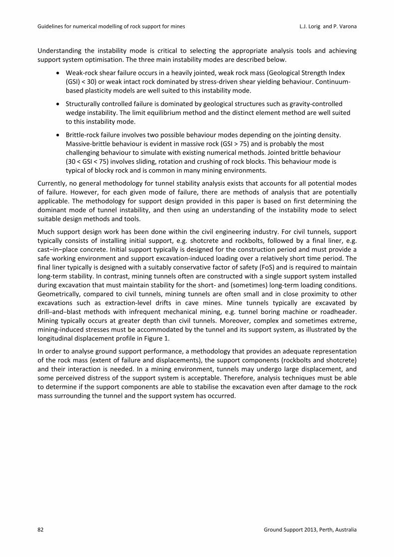
Much support design work has been done within the civil engineering industry. For civil tunnels, support typically consists of installing initial support, e.g. shotcrete and rockbolts, followed by a final liner, e.g. cast−in−place concrete. Initial support typically is designed for the construction period and must provide a safe working environment and support excavation-induced loading over a relatively short time period. The final liner typically is designed with a suitably conservative factor of safety (FoS) and is required to maintain long-term stability. In contrast, mining tunnels often are constructed with a single support system installed during excavation that must maintain stability for the short- and (sometimes) long-term loading conditions. Geometrically, compared to civil tunnels, mining tunnels are often small and in close proximity to other excavations such as extraction-level drifts in cave mines. Mine tunnels typically are excavated by drill‒and‒blast methods with infrequent mechanical mining, e.g. tunnel boring machine or roadheader. Mining typically occurs at greater depth than civil tunnels. Moreover, complex and sometimes extreme, mining-induced stresses must be accommodated by the tunnel and its support system, as illustrated by the longitudinal displacement profile in Figure 1.
In order to analyse ground support performance, a methodology that provides an adequate representation of the rock mass (extent of failure and displacements), the support components (rockbolts and shotcrete) and their interaction is needed. In a mining environment, tunnels may undergo large displacement, and some perceived distress of the support system is acceptable. Therefore, analysis techniques must be able to determine if the support components are able to stabilise the excavation even after damage to the rock mass surrounding the tunnel and the support system has occurred.
Keynote address
Ground Support 2013, Perth, Australia 83
Figure 1 Support for civil tunnels typically is designed for excavation-induced stresses that reach a maximum at a distance approximately three tunnel diameters behind the tunnel face (X/D > 3). Mining tunnels often can experience significantly greater mining-induced stresses (and displacements)
2 Rock mass properties for use in design
Rock mass properties relevant to continuum modelling typically are derived from the GSI classification system and the Hoek–Brown strength criterion. The method involves first assessing the intact laboratory properties, e.g. strength, stiffness, and the rock mass characteristics, e.g. joint frequency, joint condition, and then using published relations and guidelines to provide representative rock mass properties. The limitations of this method are acknowledged, and at this point the approach may be as much art as science. As a result, it is advisable to carry out sensitivity analyses to determine (1) the parameters to which the problem is most sensitive; and (2) the likely range of predicted excavation response.
Currently, a methodology is under development to create a method for determining rock mass properties using a synthetic rock mass (SRM) approach (Pierce et al., 2007). This approach makes use of Particle Flow Code (PFC) numerical modelling that takes into account intact rock strength and the actual discontinuity characteristics through a discrete fracture network (DFN), in a statistical sense, to determine the rock mass behaviour. The SRM approach has been compared to an empirical approach based on rock mass classification, and the results were very satisfactory (Pierce et al., 2007) as illustrated in Figure 2. This methodology can be used first to account for anisotropic behaviour, scale effects, etc., and then to incorporate this behaviour into continuum models. At some point, this state-of-the-art methodology may become practical for direct use in tunnel-scale problems. For now, however, the GSI approach is the current state of practice.

Guidelines for numerical modelling of rock support for mines L.J. Lorig and P. Varona
84 Ground Support 2013, Perth, Australia
Figure 2 Rock mass strength estimates using SRM (above) and Laubscher and Jakubec (2001) empirical approaches (below)
2.1 Peak-strength rock mass parameters
A moderately jointed rock mass (30 < GSI < 75) with three or more joint sets considered to behave as an isotropic material can be represented by the Hoek–Brown criterion (Equation (1)) for rock mass behaviour.
31 3 ci
ci
a
bm s
(1)
Where σci is the uniaxial compressive strength of the intact rock and the dimensionless parameters σ3/σci, mb and s are used to modify the contribution of to the rock mass strength, depending on the confining stress (σ3/σci), the degree of block interlocking (mb) and the condition of the inter-block surfaces(s). For the in situ rock mass, estimates of the disturbance factor (D) and GSI are used to estimate
Keynote address
Ground Support 2013, Perth, Australia 85
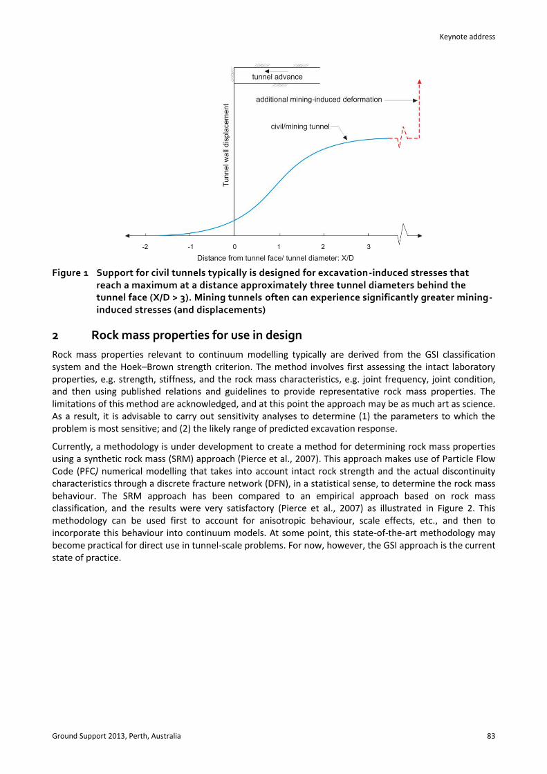
Hoek–Brown parameter s, as shown in Equation (2). This parameter is analogous to the cohesive component of the Hoek‒Brown criterion.
1009 3
GSID
s e
(2)
The relations used to estimate bm (similar to friction angle) and a are given as:
100
28 14
GSI
D
b im m e
(3)
15 20 3
1 1
2 6GSIa e e
(4)
Based on the Hoek–Brown envelope defined by these parameters, the unconfined compressive strength and tensile strengths of the rock mass can be determined as:
a
c cis (5)
cit
b
s
m
(6)
For intact rock, or unjointed rock masses, some practitioners suggest that the Hoek–Brown envelope over predicts the tensile strength. A more accurate assessment of the tensile strength can be determined by finding the intersection of a line passing through the origin with a -3:1 slope and the Hoek–Brown
envelope. The value of 3 at this point is a good estimate of tensile strength for intact rock (Hoek, 1965).
The global rock mass strength, σcm, can be estimated based on the laboratory unconfined compressive strength, σcm, and other Hoek–Brown parameters using the following equation (Hoek et al., 2002):
14 8 / 4
2 1 2
a
b b b
cm ci
m s a m s m s
a a
(7)
For the Mohr-Coulomb-based failure criterion, which is used for some analysis methods, the Hoek–Brown envelope can be linearised over an appropriate stress range for the anticipated tunnel in situ stress conditions as described by Hoek et al. (2002). For improved accuracy over a wider stress range, a bilinear Mohr-Coulomb based model can be obtained using curve-fitting techniques to determine linearised properties below the confining stress corresponding to the elastic–plastic transition, i.e. plastic zone.
2.2 Disturbance factor
Hoek et al. (2002) proposed the factor D as a means to account for blast damage and stress relaxation around excavations. It varies from 0 for undisturbed rock masses to 1 for very disturbed rock masses. For tunnels, properties adjusted for the damage factor should be limited to a disturbed region around the tunnel boundary, e.g. 0.5 to 2 m, and should not be applied to the entire rock mass. A detailed investigation into blast-induced damage around tunnels is described by Saiang (2008).
2.3 Elastic rock mass parameters
Hoek and Diederichs (2006) derived two approaches for estimating the Young’s modulus of a rock mass. One is a simplified approach:
75 25 11
1 2( ) 1 5
1rm
D GSI
DE MPa e
e
(8)
Guidelines for numerical modelling of rock support for mines L.J. Lorig and P. Varona
86 Ground Support 2013, Perth, Australia
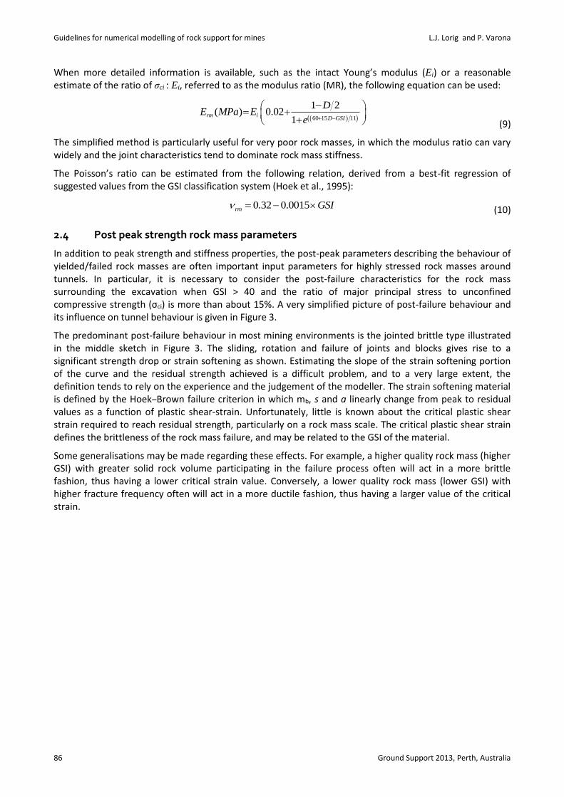
When more detailed information is available, such as the intact Young’s modulus (Ei) or a reasonable estimate of the ratio of σci : Ei, referred to as the modulus ratio (MR), the following equation can be used:
60 15 11
1 2( ) 0.02
1rm i
D GSI
DE MPa E
e
(9)
The simplified method is particularly useful for very poor rock masses, in which the modulus ratio can vary widely and the joint characteristics tend to dominate rock mass stiffness.
The Poisson’s ratio can be estimated from the following relation, derived from a best-fit regression of suggested values from the GSI classification system (Hoek et al., 1995):
0.32 0.0015rm GSI (10)
2.4 Post peak strength rock mass parameters
In addition to peak strength and stiffness properties, the post-peak parameters describing the behaviour of yielded/failed rock masses are often important input parameters for highly stressed rock masses around tunnels. In particular, it is necessary to consider the post-failure characteristics for the rock mass surrounding the excavation when GSI > 40 and the ratio of major principal stress to unconfined compressive strength (σci) is more than about 15%. A very simplified picture of post-failure behaviour and its influence on tunnel behaviour is given in Figure 3.
The predominant post-failure behaviour in most mining environments is the jointed brittle type illustrated in the middle sketch in Figure 3. The sliding, rotation and failure of joints and blocks gives rise to a significant strength drop or strain softening as shown. Estimating the slope of the strain softening portion of the curve and the residual strength achieved is a difficult problem, and to a very large extent, the definition tends to rely on the experience and the judgement of the modeller. The strain softening material is defined by the Hoek‒Brown failure criterion in which mb, s and a linearly change from peak to residual values as a function of plastic shear-strain. Unfortunately, little is known about the critical plastic shear strain required to reach residual strength, particularly on a rock mass scale. The critical plastic shear strain defines the brittleness of the rock mass failure, and may be related to the GSI of the material.
Some generalisations may be made regarding these effects. For example, a higher quality rock mass (higher GSI) with greater solid rock volume participating in the failure process often will act in a more brittle fashion, thus having a lower critical strain value. Conversely, a lower quality rock mass (lower GSI) with higher fracture frequency often will act in a more ductile fashion, thus having a larger value of the critical strain.

Keynote address
Ground Support 2013, Perth, Australia 87
Figure 3 Simplified post-failure characteristics and tunnel behaviour
An estimate of the relation between the critical strain and GSI was determined by a back-analysis of rock mass failure in caves and other openings as a part of the International Caving Study (Brown, 2003). The estimate provides a starting point for describing the critical plastic shear strain to be used:
critical strain = (12.5 – 0.125 × GSI) / (100) (11)
However, if localisation (i.e. shear bands) is evident in the model, then the critical strain needs to be scaled to zone size as follows:
critical strain = (12.5 – 0.125 × GSI) / (100 × d) (12)
Where:
d = zone size (cube root of zone volume).
Guidelines for numerical modelling of rock support for mines L.J. Lorig and P. Varona
88 Ground Support 2013, Perth, Australia
The presence of zone size within this relation recognises that the critical strain parameter is zone-size dependent in continuum models where shearing tends to be resolved in a band approximately one zone thick. Work is underway to determine the full stress-strain response of a jointed rock mass more rigorously (and thus, the critical strain) by using the SRM approach.
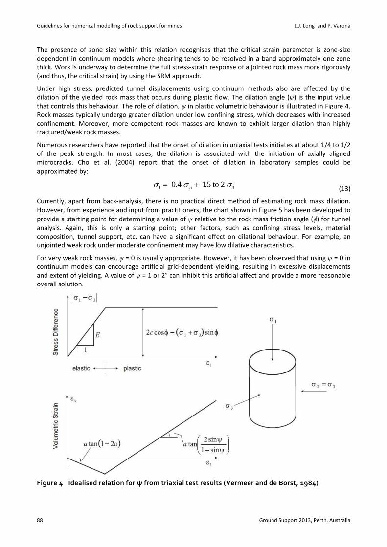
Under high stress, predicted tunnel displacements using continuum methods also are affected by the dilation of the yielded rock mass that occurs during plastic flow. The dilation angle (ψ) is the input value that controls this behaviour. The role of dilation, ψ in plastic volumetric behaviour is illustrated in Figure 4. Rock masses typically undergo greater dilation under low confining stress, which decreases with increased confinement. Moreover, more competent rock masses are known to exhibit larger dilation than highly fractured/weak rock masses.
Numerous researchers have reported that the onset of dilation in uniaxial tests initiates at about 1/4 to 1/2 of the peak strength. In most cases, the dilation is associated with the initiation of axially aligned microcracks. Cho et al. (2004) report that the onset of dilation in laboratory samples could be approximated by:
1 ci 3 0.4 1.5 to 2 (13)
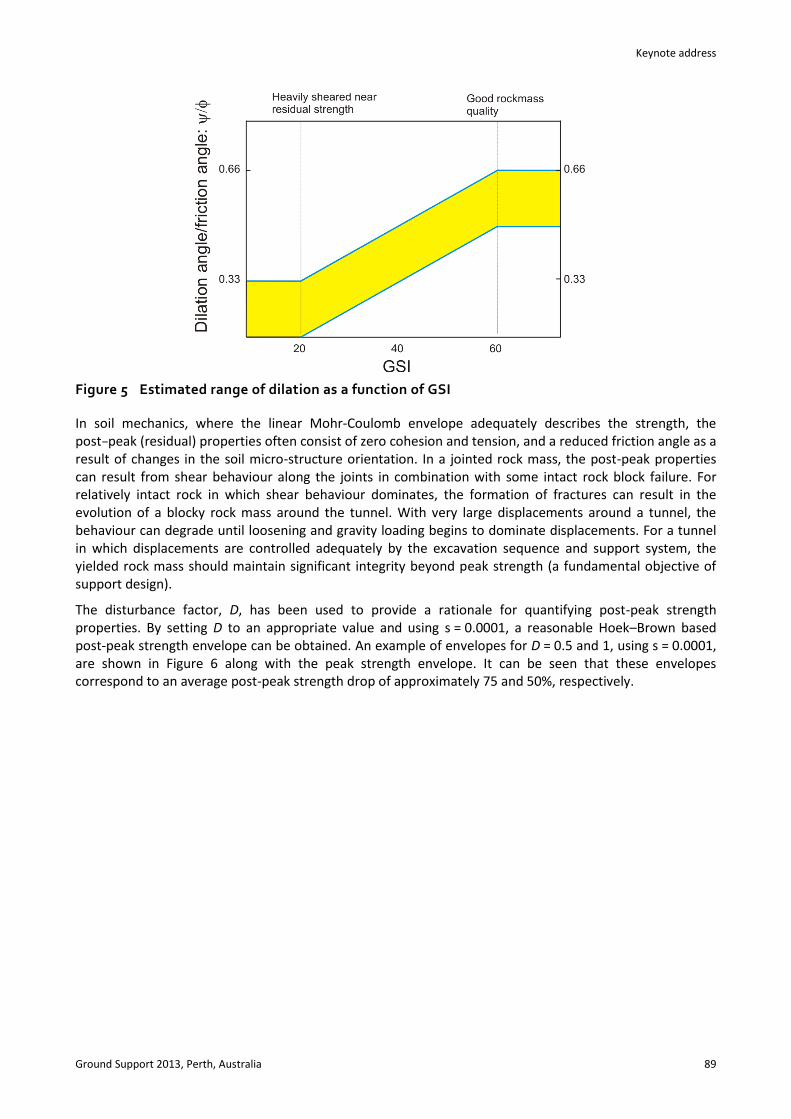
Currently, apart from back-analysis, there is no practical direct method of estimating rock mass dilation. However, from experience and input from practitioners, the chart shown in Figure 5 has been developed to
provide a starting point for determining a value of ψ relative to the rock mass friction angle () for tunnel analysis. Again, this is only a starting point; other factors, such as confining stress levels, material composition, tunnel support, etc. can have a significant effect on dilational behaviour. For example, an unjointed weak rock under moderate confinement may have low dilative characteristics.
For very weak rock masses, ψ = 0 is usually appropriate. However, it has been observed that using ψ = 0 in continuum models can encourage artificial grid-dependent yielding, resulting in excessive displacements and extent of yielding. A value of ψ = 1 or 2° can inhibit this artificial affect and provide a more reasonable overall solution.
Figure 4 Idealised relation for ψ from triaxial test results (Vermeer and de Borst, 1984)
Keynote address
Ground Support 2013, Perth, Australia 89
Figure 5 Estimated range of dilation as a function of GSI
In soil mechanics, where the linear Mohr-Coulomb envelope adequately describes the strength, the post−peak (residual) properties often consist of zero cohesion and tension, and a reduced friction angle as a result of changes in the soil micro-structure orientation. In a jointed rock mass, the post-peak properties can result from shear behaviour along the joints in combination with some intact rock block failure. For relatively intact rock in which shear behaviour dominates, the formation of fractures can result in the evolution of a blocky rock mass around the tunnel. With very large displacements around a tunnel, the behaviour can degrade until loosening and gravity loading begins to dominate displacements. For a tunnel in which displacements are controlled adequately by the excavation sequence and support system, the yielded rock mass should maintain significant integrity beyond peak strength (a fundamental objective of support design).
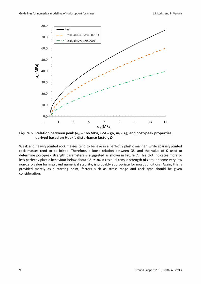
The disturbance factor, D, has been used to provide a rationale for quantifying post-peak strength properties. By setting D to an appropriate value and using s = 0.0001, a reasonable Hoek–Brown based post-peak strength envelope can be obtained. An example of envelopes for D = 0.5 and 1, using s = 0.0001, are shown in Figure 6 along with the peak strength envelope. It can be seen that these envelopes correspond to an average post-peak strength drop of approximately 75 and 50%, respectively.
Guidelines for numerical modelling of rock support for mines L.J. Lorig and P. Varona
90 Ground Support 2013, Perth, Australia
Figure 6 Relation between peak (σci = 100 MPa, GSI = 50, mi = 15) and post-peak properties derived based on Hoek’s disturbance factor, D
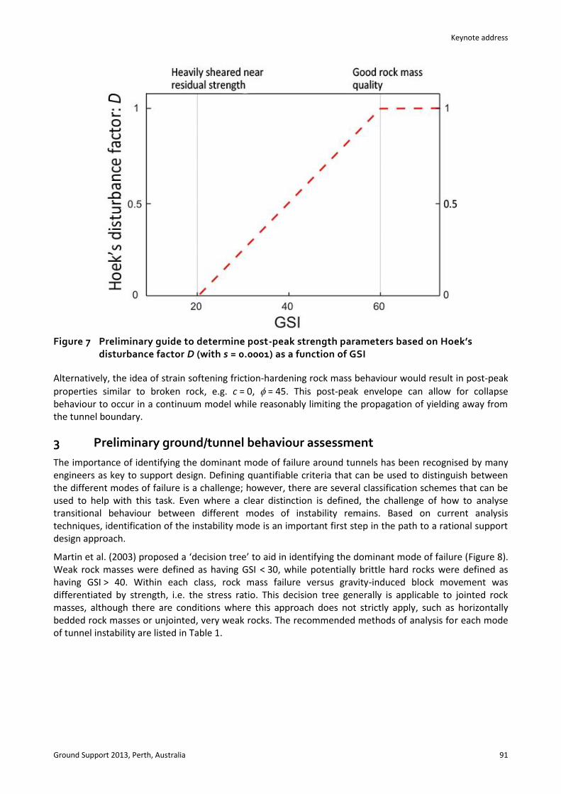
Weak and heavily jointed rock masses tend to behave in a perfectly plastic manner, while sparsely jointed rock masses tend to be brittle. Therefore, a loose relation between GSI and the value of D used to determine post-peak strength parameters is suggested as shown in Figure 7. This plot indicates more or less perfectly plastic behaviour below about GSI = 30. A residual tensile strength of zero, or some very low non-zero value for improved numerical stability, is probably appropriate for most conditions. Again, this is provided merely as a starting point; factors such as stress range and rock type should be given consideration.
Keynote address
Ground Support 2013, Perth, Australia 91
Figure 7 Preliminary guide to determine post-peak strength parameters based on Hoek’s disturbance factor D (with s = 0.0001) as a function of GSI
Alternatively, the idea of strain softening friction-hardening rock mass behaviour would result in post-peak
properties similar to broken rock, e.g. c = 0, = 45. This post-peak envelope can allow for collapse behaviour to occur in a continuum model while reasonably limiting the propagation of yielding away from the tunnel boundary.
3 Preliminary ground/tunnel behaviour assessment
The importance of identifying the dominant mode of failure around tunnels has been recognised by many engineers as key to support design. Defining quantifiable criteria that can be used to distinguish between the different modes of failure is a challenge; however, there are several classification schemes that can be used to help with this task. Even where a clear distinction is defined, the challenge of how to analyse transitional behaviour between different modes of instability remains. Based on current analysis techniques, identification of the instability mode is an important first step in the path to a rational support design approach.
Martin et al. (2003) proposed a ‘decision tree’ to aid in identifying the dominant mode of failure (Figure 8). Weak rock masses were defined as having GSI < 30, while potentially brittle hard rocks were defined as having GSI > 40. Within each class, rock mass failure versus gravity-induced block movement was differentiated by strength, i.e. the stress ratio. This decision tree generally is applicable to jointed rock masses, although there are conditions where this approach does not strictly apply, such as horizontally bedded rock masses or unjointed, very weak rocks. The recommended methods of analysis for each mode of tunnel instability are listed in Table 1.

Guidelines for numerical modelling of rock support for mines L.J. Lorig and P. Varona
92 Ground Support 2013, Perth, Australia
Figure 8 Instability mode based on rock quality (GSI), intact rock strength and stress level (Martin et al., 2003)
Table 1 Recommended analysis methods for each mode of tunnel instability
Instability Mode
Analysis Approach
Weak Rock Shear Failure
Structurally Controlled Instability Brittle Rock Failure
Empirical Hoek squeezing chart (Hoek and Marinos, 2000), Chern Criteria (Chern et al., 1998)
Martin’s empirical df (Martin et al., 1999)
Kaiser’s brittle strain (Kaiser et al., 2000)
Analytical Plasticity based closed-form solutions (Duncan-Fama,
1993; Carranza-Torres and Fairhurst, 1999)
Limit equilibrium (Hudson and Harrison, 2000) (e.g. UNWEDGE)
Elastic Closed form solutions for stress (Kirsch, 1898)
with constant deviatoric criterion (Martin et al., 1999)
Numerical
Modelling
Two- and three-dimensional continuum methods
Two- and three−dimensional
discontinuum methods
Two- and three-dimensional continuum methods and discontinuum methods
4 Simulation of tunnel advance in two dimensions
An important consideration in performing tunnel analysis is determining the correct amount of tunnel closure that occurs prior to installation of ground support. In order to simulate the excavation and ground support sequence correctly, a methodology has been developed to account for three-dimensional tunnel advance using two-dimensional numerical models or closed-form solutions. The technique involves generating two curves: one that relates internal support pressure (pi) to tunnel displacement, known as the ground response curve (GRC); and a second that relates tunnel displacement to distance from the excavation face, known as a longitudinal tunnel-displacement profile (LDP). Using both of these curves, a relation between distance from the face and pi is obtained that can be used to simulate the three−dimensional effects of tunnel advance using two-dimensional analysis methods. This approach can be seen conceptually in Figure 9, which shows how reducing tunnel wall pressure can represent tunnel behaviour during face advance and a typical GRC. The ratio pi/p0 is referred to as the relaxation factor (Rf).

Keynote address
Ground Support 2013, Perth, Australia 93
The GRC can be developed for a given cross-section and tunnelling condition by calculating and plotting tunnel closure for a range of internal support pressure (pi). The incremental reduction of the internal support pressure represents the effect of the advancing tunnel face. Knowing the installed support distance from the tunnel face and having the LDP, we can estimate the amount of tunnel deformation that occurs prior to support installation. The LDP can be determined by several means: empirical, analytical and numerical. Vlachopoulos and Diederichs (2009) show that the characteristic shape of the LDP is strongly related to the extent of the yielded zone around tunnels, particularly when yielding around the tunnel periphery is influenced by yielding near the tunnel face. For tunnels with an extensive zone of failure, i.e. radius of plastic zone exceeds two tunnel radii, significant errors can be introduced by not accounting for the interaction of face and tunnel periphery yielding. The chart in Figure 10, developed for circular tunnels, provides LDP curves. The equations for the curves can be found in Vlachopoulos and Diederichs (2009). For more complex tunnelling conditions involving non-circular tunnels, non-hydrostatic stress fields or when face stability must be accessed directly, three-dimensional numerical modelling may be required. When using two-dimensional models in conjunction with LDP, a numerical GRC is required.
Figure 9 Schematic of the internal stress-reduction technique used to simulate 3D tunnel advance using 2D models (top) and a typical GRC (bottom)

Guidelines for numerical modelling of rock support for mines L.J. Lorig and P. Varona
94 Ground Support 2013, Perth, Australia
Figure 10 Longitudinal displacement profile as a function of the extent of plastic zone around a tunnel (Vlachopoulos and Diederichs, 2009)
5 Weak rock shear failure
The term weak rock mass refers to more than a low strength-to-stress ratio; it also refers to a shear-yielding dominated mode of failure. From this perspective, weak rock masses consist of either weak intact rock or heavily jointed rock masses, both of which fail in a shear mode under high stress. The shear mode of yielding can be identified based on rock mass quality and strength-to-stress ratio, as shown in Figure 8. Tunnels in highly stressed weak rock often experience large tunnel strain that can pose challenges for support design. Under these conditions, the tunnel support system must be capable of accommodating large strains while maintaining tunnel stability.
Although shear failure is well understood in an engineering sense, the behaviour of weak rock can be very complex. Tunnel closure in weak rock often has a time-dependent component due to creep, time-dependent strength degradation, pore pressure redistribution, swelling or other mechanisms. It often is difficult to determine precisely which mechanism is occurring, and typically large tunnel deformations in weak rock are due to some combination of mechanisms. In general, the large, inward tunnel deformations in weak rock are divided into two classes: swelling and squeezing. Several authors (summarised by Barla, 1995) have proposed definitions for these two mechanisms, but it has been suggested that a precise definition of the mechanism is not practical for the tunnelling engineer (Panet, 1995; Aydan et al., 1993). Materials that are prone to significant swelling are of less interest for the mining tunnels being considered in this paper; for the most part, this section concentrates on the plastic yielding/squeezing mechanism.
Tunnel strain curves based on Monte Carlo simulations using closed-form solutions (Hoek and Marinos, 2000) and continuum modelling (Hoek, 2001) provide a useful and straightforward first-approximation for predicting the tunnel strain that can be anticipated for an unsupported circular excavation within weak rock masses, i.e. low GSI, under an isotropic stress field. In the time since Hoek proposed these curves, there
have been changes to the method of estimating rmE and cm that affect the use of these curves.
The standard tunnel strain curve has been revised to include the updated parameters described above, and refined it to include a wider range of properties and in situ stresses ratios (k) using the statistical-based design of experiment (DOE) technique. Details of the technique and resulting design curves are provided in
Keynote address
Ground Support 2013, Perth, Australia 95
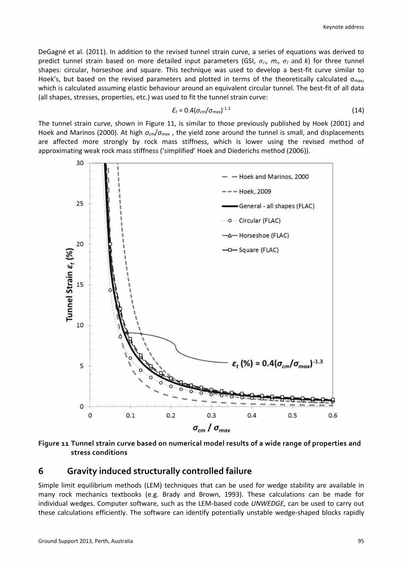
DeGagné et al. (2011). In addition to the revised tunnel strain curve, a series of equations was derived to predict tunnel strain based on more detailed input parameters (GSI, σci, mi, σ1 and k) for three tunnel shapes: circular, horseshoe and square. This technique was used to develop a best-fit curve similar to Hoek’s, but based on the revised parameters and plotted in terms of the theoretically calculated σmax, which is calculated assuming elastic behaviour around an equivalent circular tunnel. The best-fit of all data (all shapes, stresses, properties, etc.) was used to fit the tunnel strain curve:
Ɛt = 0.4(σcm/σmax)-1.3 (14)
The tunnel strain curve, shown in Figure 11, is similar to those previously published by Hoek (2001) and Hoek and Marinos (2000). At high σcm/σmax , the yield zone around the tunnel is small, and displacements are affected more strongly by rock mass stiffness, which is lower using the revised method of approximating weak rock mass stiffness (‘simplified’ Hoek and Diederichs method (2006)).
Figure 11 Tunnel strain curve based on numerical model results of a wide range of properties and stress conditions
6 Gravity induced structurally controlled failure
Simple limit equilibrium methods (LEM) techniques that can be used for wedge stability are available in many rock mechanics textbooks (e.g. Brady and Brown, 1993). These calculations can be made for individual wedges. Computer software, such as the LEM-based code UNWEDGE, can be used to carry out these calculations efficiently. The software can identify potentially unstable wedge-shaped blocks rapidly

Guidelines for numerical modelling of rock support for mines L.J. Lorig and P. Varona
96 Ground Support 2013, Perth, Australia
for a given excavation shape, orientation and series of joint sets, and calculate the FoS of all potential wedges. The software also can take into account in situ stresses, and can be used for statistical analyses and sensitivity calculations. Finally, the software can account for rockbolt and shotcrete support in the FoS calculation. This is sufficient analysis for most practical problems. Figure 12 shows an example of the UNWEDGE software. More advanced programs, e.g. Elmouttie et al. (2010), allow for the use of all properties associated with a three-dimensional DFN, including the spatial distribution of joints and other structures. The analyses are not limited to statistical representations of these structures, but include representations of the actual structures mapped in the field across (potentially large) exposures. Further, the polyhedral blocks analysed can have unlimited number of faces or shape, therefore accommodating more realistic DFN generation.
Figure 12 Wedges formed around a tunnel with three joint sets along with LEM-calculated FoS for an unsupported tunnel
It should be pointed out that UNWEDGE calculates FoS based purely on a ‘punching’ shear-failure mode of shotcrete failure. Note that the punching mode of shotcrete failure is often not the critical failure model; instead, a bending mode of failure is often the critical failure mode for wedge instability. Bending-induced shotcrete failure can occur at much lower strengths, i.e. lower FoS, than punching failure.
6.1 Numerical modelling
Distinct Element Method (DEM) codes are particularly well suited to modelling tunnels in jointed rock masses where the geological structure dominates the problem. Two- and three-dimensional DEM codes simulate a jointed rock mass by breaking up the continuum into a series of blocks that are internally discretised into finite difference or finite element zones. Movement and failure can occur between blocks, along joints or within blocks as determined by the stress–strain behaviour and failure criterion. The interaction between blocks is controlled by joint material models, e.g. Mohr–Coulomb; the behaviour within the blocks is controlled by zone/block material models, e.g. Mohr–Coulomb. The numerical scheme allows for large deformations and detachment of blocks to occur within the model while achieving accurate solutions.
Keynote address
Ground Support 2013, Perth, Australia 97
In addition to being able to simulate the rock mass adequately, for the purposes of tunnel support design, the simulations also must have the capability to include the individual ground support components, such as rockbolts and shotcrete liners.
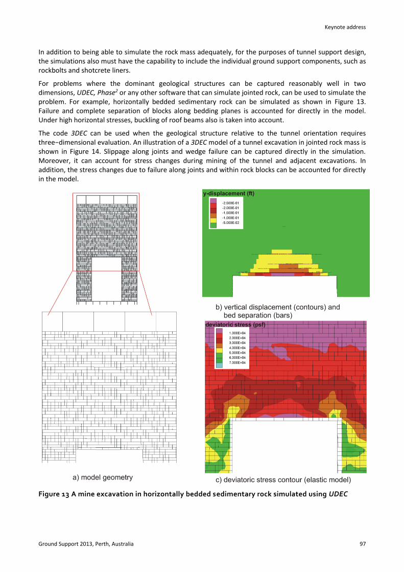
For problems where the dominant geological structures can be captured reasonably well in two dimensions, UDEC, Phase2 or any other software that can simulate jointed rock, can be used to simulate the problem. For example, horizontally bedded sedimentary rock can be simulated as shown in Figure 13. Failure and complete separation of blocks along bedding planes is accounted for directly in the model. Under high horizontal stresses, buckling of roof beams also is taken into account.
The code 3DEC can be used when the geological structure relative to the tunnel orientation requires three−dimensional evaluation. An illustration of a 3DEC model of a tunnel excavation in jointed rock mass is shown in Figure 14. Slippage along joints and wedge failure can be captured directly in the simulation. Moreover, it can account for stress changes during mining of the tunnel and adjacent excavations. In addition, the stress changes due to failure along joints and within rock blocks can be accounted for directly in the model.
Figure 13 A mine excavation in horizontally bedded sedimentary rock simulated using UDEC

Guidelines for numerical modelling of rock support for mines L.J. Lorig and P. Varona
98 Ground Support 2013, Perth, Australia
Figure 14 Example of a 3DEC model of a tunnel with an unstable roof wedge
7 Stress-induced brittle behaviour
As mentioned in the introduction, stress-induced brittle failure takes two forms, namely massive-brittle and jointed brittle. Modelling of massive-brittle behaviour by continuum models is presented by Corkum et al. (2012) and is not discussed here. Jointed brittle behaviour is more common in mining environments and modelling of this behaviour typically involves strain softening behaviour as discussed in the following examples.
7.1 Two-dimensional tunnel analysis
In this example, an isolated tunnel is studied to determine the support deformation compatibility for an isolated horseshoe-shaped tunnel (4.5 m wide × 4.75 m high). The in situ stresses are 21 MPa (in-plane horizontal), 16 MPa (vertical) and 27 MPa (horizontal out-of-plane). The rock mass parameters shown in Table 2 were used in a strain softening model, as described in Section 2. The in situ stresses, GSI and unconfined compressive strength suggest jointed brittle behaviour. The residual behaviour is assumed to result in a cohesionless material with a friction angle of about 45°.
Table 2 Rock mass parameters for example tunnel exhibiting jointed brittle behaviour
Peak Parameters
GSI = 50
55ci MPa
20im
25iE GPa
Residual Parameters
4.33rm
0rs
1ra
The procedure outlined by Vlachopulous and Diederichs (2009) is used to estimate that the internal pressure, pi, at the time the support is installed about 3 m behind the face is 1.8% of the initial in situ stress.
Keynote address
Ground Support 2013, Perth, Australia 99
The bolt parameters, including bolt/rock interface properties were determined using the following procedure taking into account the age of the grout at the time of installation. The elastic modulus and annular thickness of the grout were used to calculate the stiffness (Kbond) for the bolt/rock interface as shown in Equation (15) modified from St. John and Van Dillen (1983):
2
210ln 1
grout
bond
GK
tD
(15)
Where:
Ggrout = shear modulus of the grout.
t = annular thickness between bolt and rock.
D = bolt diameter.
The grout shear strength was determined from pull-out tests to be 800 kN/m.
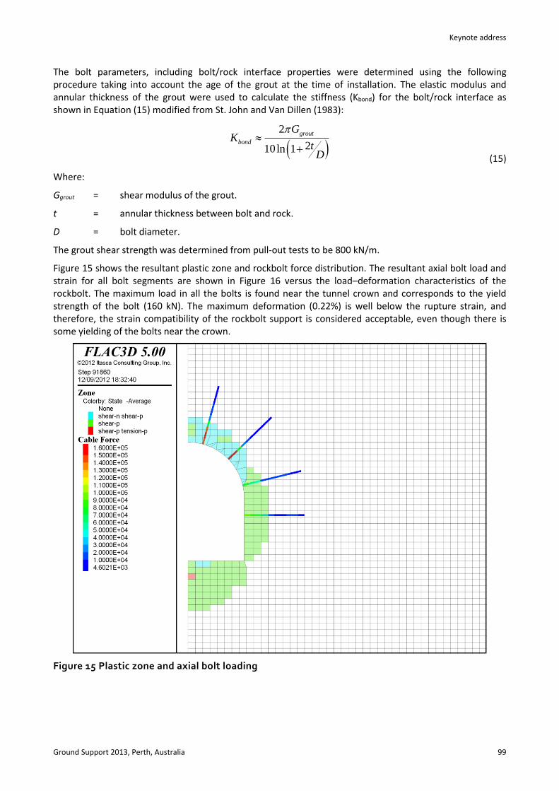
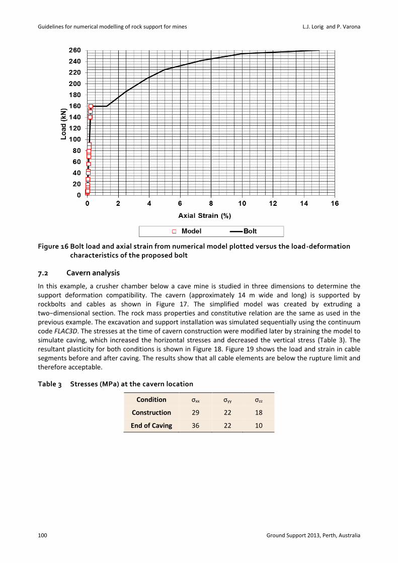
Figure 15 shows the resultant plastic zone and rockbolt force distribution. The resultant axial bolt load and strain for all bolt segments are shown in Figure 16 versus the load–deformation characteristics of the rockbolt. The maximum load in all the bolts is found near the tunnel crown and corresponds to the yield strength of the bolt (160 kN). The maximum deformation (0.22%) is well below the rupture strain, and therefore, the strain compatibility of the rockbolt support is considered acceptable, even though there is some yielding of the bolts near the crown.
Figure 15 Plastic zone and axial bolt loading
Guidelines for numerical modelling of rock support for mines L.J. Lorig and P. Varona
100 Ground Support 2013, Perth, Australia
Figure 16 Bolt load and axial strain from numerical model plotted versus the load-deformation characteristics of the proposed bolt
7.2 Cavern analysis
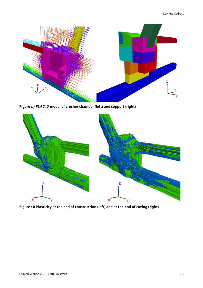
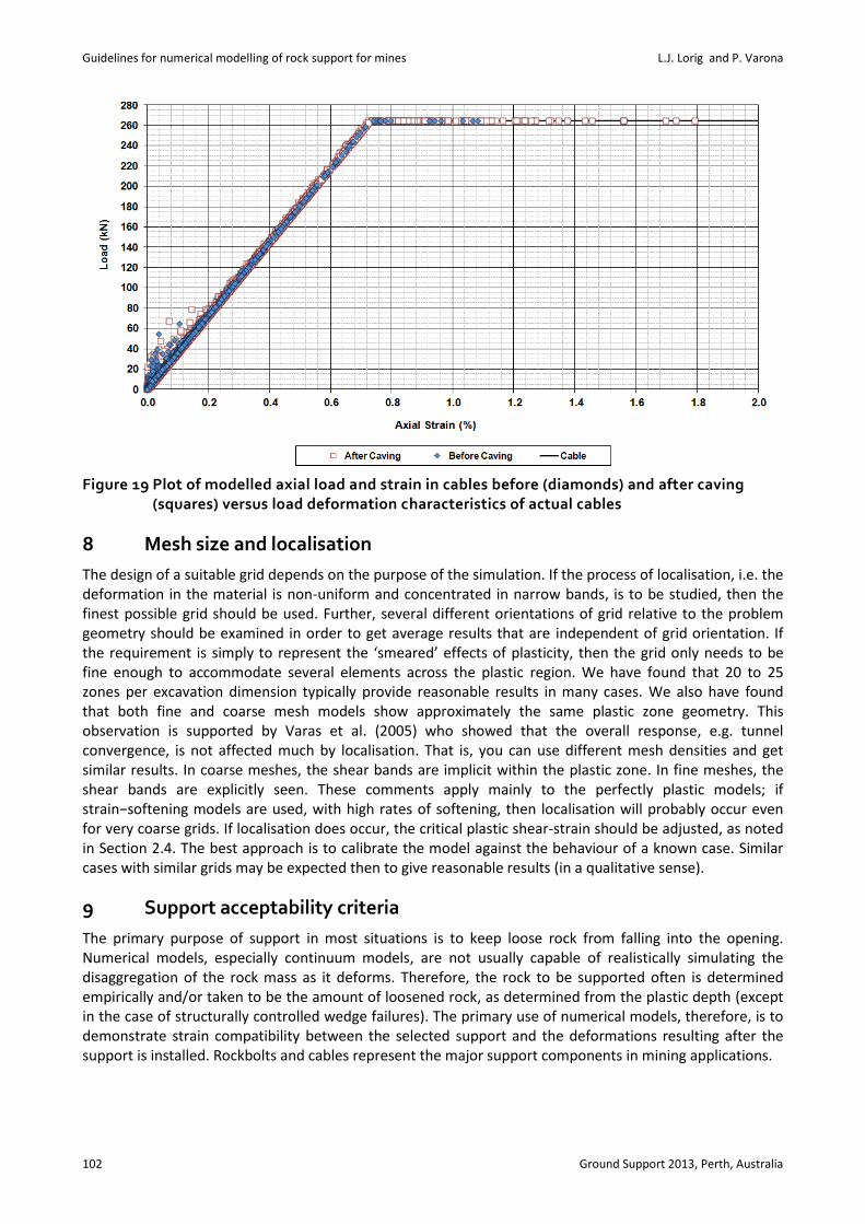
In this example, a crusher chamber below a cave mine is studied in three dimensions to determine the support deformation compatibility. The cavern (approximately 14 m wide and long) is supported by rockbolts and cables as shown in Figure 17. The simplified model was created by extruding a two−dimensional section. The rock mass properties and constitutive relation are the same as used in the previous example. The excavation and support installation was simulated sequentially using the continuum code FLAC3D. The stresses at the time of cavern construction were modified later by straining the model to simulate caving, which increased the horizontal stresses and decreased the vertical stress (Table 3). The resultant plasticity for both conditions is shown in Figure 18. Figure 19 shows the load and strain in cable segments before and after caving. The results show that all cable elements are below the rupture limit and therefore acceptable.
Table 3 Stresses (MPa) at the cavern location
Condition σxx σyy σzz
Construction 29 22 18
End of Caving 36 22 10
Keynote address
Ground Support 2013, Perth, Australia 101
Figure 17 FLAC3D model of crusher chamber (left) and support (right)
Figure 18 Plasticity at the end of construction (left) and at the end of caving (right)
Guidelines for numerical modelling of rock support for mines L.J. Lorig and P. Varona
102 Ground Support 2013, Perth, Australia
Figure 19 Plot of modelled axial load and strain in cables before (diamonds) and after caving (squares) versus load deformation characteristics of actual cables
8 Mesh size and localisation
The design of a suitable grid depends on the purpose of the simulation. If the process of localisation, i.e. the deformation in the material is non-uniform and concentrated in narrow bands, is to be studied, then the finest possible grid should be used. Further, several different orientations of grid relative to the problem geometry should be examined in order to get average results that are independent of grid orientation. If the requirement is simply to represent the ‘smeared’ effects of plasticity, then the grid only needs to be fine enough to accommodate several elements across the plastic region. We have found that 20 to 25 zones per excavation dimension typically provide reasonable results in many cases. We also have found that both fine and coarse mesh models show approximately the same plastic zone geometry. This observation is supported by Varas et al. (2005) who showed that the overall response, e.g. tunnel convergence, is not affected much by localisation. That is, you can use different mesh densities and get similar results. In coarse meshes, the shear bands are implicit within the plastic zone. In fine meshes, the shear bands are explicitly seen. These comments apply mainly to the perfectly plastic models; if strain−softening models are used, with high rates of softening, then localisation will probably occur even for very coarse grids. If localisation does occur, the critical plastic shear-strain should be adjusted, as noted in Section 2.4. The best approach is to calibrate the model against the behaviour of a known case. Similar cases with similar grids may be expected then to give reasonable results (in a qualitative sense).
9 Support acceptability criteria
The primary purpose of support in most situations is to keep loose rock from falling into the opening. Numerical models, especially continuum models, are not usually capable of realistically simulating the disaggregation of the rock mass as it deforms. Therefore, the rock to be supported often is determined empirically and/or taken to be the amount of loosened rock, as determined from the plastic depth (except in the case of structurally controlled wedge failures). The primary use of numerical models, therefore, is to demonstrate strain compatibility between the selected support and the deformations resulting after the support is installed. Rockbolts and cables represent the major support components in mining applications.

Keynote address
Ground Support 2013, Perth, Australia 103
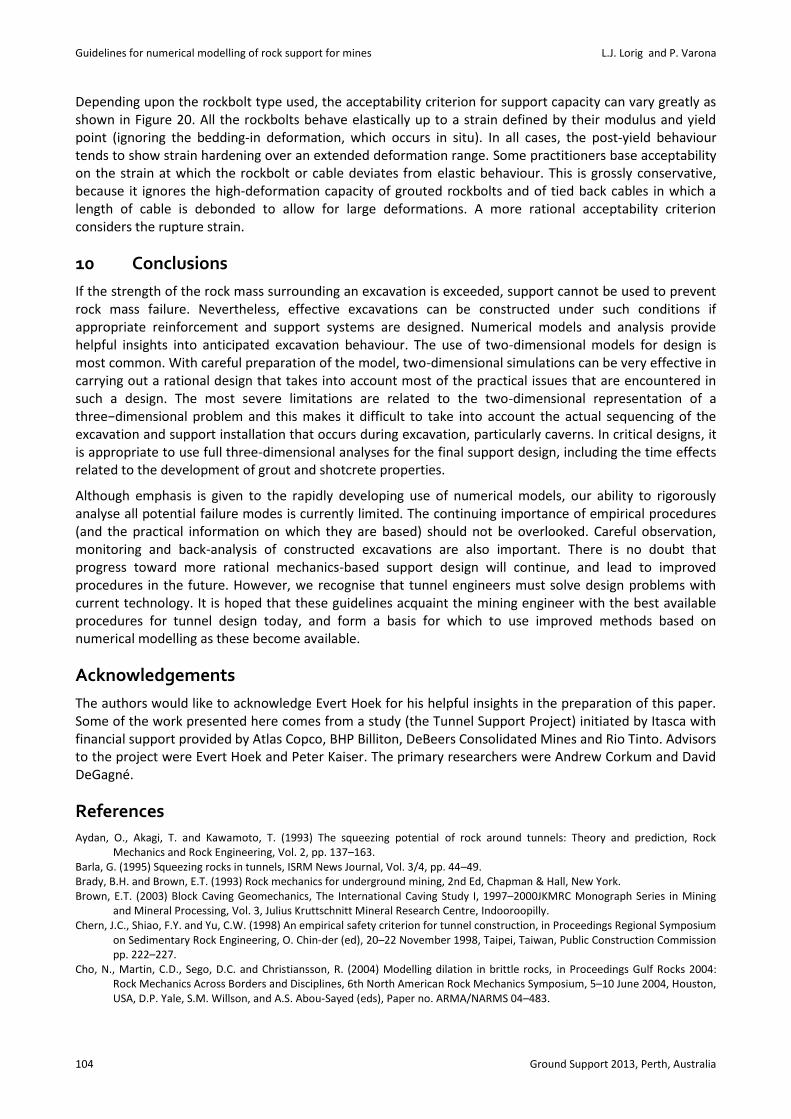
Figure 20 Maximum capacity and deformation characteristics of typical rockbolts (Hoek, 2010)
Guidelines for numerical modelling of rock support for mines L.J. Lorig and P. Varona
104 Ground Support 2013, Perth, Australia
Depending upon the rockbolt type used, the acceptability criterion for support capacity can vary greatly as shown in Figure 20. All the rockbolts behave elastically up to a strain defined by their modulus and yield point (ignoring the bedding-in deformation, which occurs in situ). In all cases, the post-yield behaviour tends to show strain hardening over an extended deformation range. Some practitioners base acceptability on the strain at which the rockbolt or cable deviates from elastic behaviour. This is grossly conservative, because it ignores the high-deformation capacity of grouted rockbolts and of tied back cables in which a length of cable is debonded to allow for large deformations. A more rational acceptability criterion considers the rupture strain.
10 Conclusions
If the strength of the rock mass surrounding an excavation is exceeded, support cannot be used to prevent rock mass failure. Nevertheless, effective excavations can be constructed under such conditions if appropriate reinforcement and support systems are designed. Numerical models and analysis provide helpful insights into anticipated excavation behaviour. The use of two-dimensional models for design is most common. With careful preparation of the model, two-dimensional simulations can be very effective in carrying out a rational design that takes into account most of the practical issues that are encountered in such a design. The most severe limitations are related to the two-dimensional representation of a three−dimensional problem and this makes it difficult to take into account the actual sequencing of the excavation and support installation that occurs during excavation, particularly caverns. In critical designs, it is appropriate to use full three-dimensional analyses for the final support design, including the time effects related to the development of grout and shotcrete properties.
Although emphasis is given to the rapidly developing use of numerical models, our ability to rigorously analyse all potential failure modes is currently limited. The continuing importance of empirical procedures (and the practical information on which they are based) should not be overlooked. Careful observation, monitoring and back-analysis of constructed excavations are also important. There is no doubt that progress toward more rational mechanics-based support design will continue, and lead to improved procedures in the future. However, we recognise that tunnel engineers must solve design problems with current technology. It is hoped that these guidelines acquaint the mining engineer with the best available procedures for tunnel design today, and form a basis for which to use improved methods based on numerical modelling as these become available.
Acknowledgements
The authors would like to acknowledge Evert Hoek for his helpful insights in the preparation of this paper. Some of the work presented here comes from a study (the Tunnel Support Project) initiated by Itasca with financial support provided by Atlas Copco, BHP Billiton, DeBeers Consolidated Mines and Rio Tinto. Advisors to the project were Evert Hoek and Peter Kaiser. The primary researchers were Andrew Corkum and David DeGagné.
References
Aydan, O., Akagi, T. and Kawamoto, T. (1993) The squeezing potential of rock around tunnels: Theory and prediction, Rock Mechanics and Rock Engineering, Vol. 2, pp. 137–163.
Barla, G. (1995) Squeezing rocks in tunnels, ISRM News Journal, Vol. 3/4, pp. 44–49. Brady, B.H. and Brown, E.T. (1993) Rock mechanics for underground mining, 2nd Ed, Chapman & Hall, New York. Brown, E.T. (2003) Block Caving Geomechanics, The International Caving Study I, 1997–2000JKMRC Monograph Series in Mining
and Mineral Processing, Vol. 3, Julius Kruttschnitt Mineral Research Centre, Indooroopilly. Chern, J.C., Shiao, F.Y. and Yu, C.W. (1998) An empirical safety criterion for tunnel construction, in Proceedings Regional Symposium
on Sedimentary Rock Engineering, O. Chin-der (ed), 20–22 November 1998, Taipei, Taiwan, Public Construction Commission pp. 222–227.
Cho, N., Martin, C.D., Sego, D.C. and Christiansson, R. (2004) Modelling dilation in brittle rocks, in Proceedings Gulf Rocks 2004: Rock Mechanics Across Borders and Disciplines, 6th North American Rock Mechanics Symposium, 5–10 June 2004, Houston, USA, D.P. Yale, S.M. Willson, and A.S. Abou-Sayed (eds), Paper no. ARMA/NARMS 04–483.
Keynote address
Ground Support 2013, Perth, Australia 105
Carranza-Torres, C., and Fairhurst, C. (1999) General formulation of the elasto-plastic response of openings in rock using the Hoek−Brown failure criterion, International Journal of Rock Mechanics and Mining Sciences, Vol. 36(6), pp. 777–809.
Corkum, A.G., Lorig, L.J. and DeGagné, D.O. (2012) Continuum representation of brittle rock failure bulking-induced displacements around tunnels, in Proceedings 46th U.S. Rock Mechanics / Geomechanics Symposium, 24–27 June 2012, Chicago, USA, American Rock Mechanics Association, Alexandria, Paper No. 12–176.
DeGagné, D.O., Corkum, A.G. and Lorig, L.J. (2011) Estimation of tunnel squeezing in anisotropic stress fields using a FLAC-based neural network, in Continuum and Distinct Element Modeling in Geomechanics – 2011, in Proceedings 2nd International FLAC/DEM Symposium, D. Sainsbury, R. Hart, C. Detournay and M. Nelson (eds), 14–16 February 2011, Melbourne, Australia, Itasca International Inc., Minneapolis, Paper 03–06, pp. 141–151.
Duncan-Fama, M.E. (1993) Numerical modeling of yield zones in weak rocks, Comprehensive rock engineering, J.A. Hudson (ed), Pergamon, Oxford, Vol. 2, pp. 49–75.
Elmouttie, M., Poropat, G. and Krähenbühl, G. (2010) Polyhedral modelling of underground excavations, Computers and Geotechnics, Vol. 37, pp. 529–535.
Hoek, E. (1965) Rock fracture under static stress conditions, Ph.D. Thesis, Faculty of Engineering, University of Cape Town, Cape Town.
Hoek, E. (2001) Big tunnels in bad rock (2000 Terzaghi lecture), Journal of Geotechnical and Geoenvironmental Engineering, American Society of Civil Engineers, Vol. 127(9), September 2001, pp. 726–740.
Hoek, E. (2010) Excavations in overstressed rock, in Proceedings Seventh South American Conference on Rock Mechanics, 2–4 December 2010, Lima, Peru.
Hoek, E. and Diederichs, M.S. (2006) Empirical estimation of rock mass modulus, International Journal of Rock Mechanics and Mining Sciences, Vol. 43, pp. 203–215.
Hoek, E., Kaiser, P.K. and Bawden, W.F. (1995) Support of underground excavations in hard rock, Balkema, Rotterdam. Hoek, E. and Marinos, P.G. (2000) Predicting tunnel squeezing problems in weak heterogeneous rock masses, Tunnels & Tunnelling
International, Vol. 132(11), pp. 45–51. Hoek, E., Carranza-Torres, C. and Corkum, B. (2002) Hoek–Brown failure criterion — 2002 edition, NARMS-TAC 2002: Mining and
Tunnelling Innovation and Opportunity, R. Hammah, W. Bawden, J. Curran and M. Telesnicki (eds), University of Toronto Press, Toronto, Vol. 1, pp. 267–273.
Hudson, J.A. and Harrison, J.P. (2000) Engineering rock mechanics — An introduction to the principles, Elsevier Scientific, Amsterdam.
Kaiser, P.K., Diederichs, M.S., Martin, C.D., Sharp, J. and Steiner, W. (2000) Underground works in hard rock tunnelling and mining, in Proceedings GeoEng2000, 19–24 November, Melbourne, Australia, Technomic Publishing, Lancaster, pp. 841–926.
Kirsch, G. (1898) Die Theorie Der Elastizitat Und Die Bedürfnisse Der Festigkeitslehre, Veit Ver Deut Ing., Vol. 42, pp. 797–807. Laubscher, D.H. and Jakubec, J. (2001) The MRMR rock mass classification for jointed rock masses, Underground Mining Methods,
Society for Mining, Metallurgy, and Exploration, Littleton, pp. 475–481. Martin, C.D., Kaiser, P.K. and Christiansson, R. (2003) Stress, instability and design of under-ground excavation, International
Journal of Rock Mechanics and Mining Sciences, Vol. 40, pp. 1,027–1,047. Martin, C.D., Kaiser, P.K. and McCreath, D.R. (1999) Hoek-–Brown parameters for predicting the depth of brittle failure around
tunnels, Canadian Geotechnical Journal, Vol. 36(1), pp. 136–151. Panet, M. (1995) Calcul des tunnels par la méthode de convergence–confinement, Presses del’Ecole Nationale des Ponts et
Chaussées, Paris. Pierce, M., Cundall, P., Potyondy, D. and Mas Ivars, D. (2007) A sytablenthetic rock mass model for jointed rock, in Rock Mechanics:
Meeting Society's Challenges and Demands, in Proceedings 1st Canada-U.S. Rock Mechanics Symposium, Vol. 1: Fundamentals, New Technologies & New Ideas, 27–31 May 2007, Vancouver, Canada, E. Eberhardt, D. Stead and T. Morrison (eds), Taylor & Francis Group, London, pp. 341–349.
Saiang, D. (2008) Blast-induced damage: A summary of Svebefo investigations, Division of Mining and Geotechnical Engineering, Luleå University of Technology, Luleå.
St. John, C.M. and Van Dillen, D.E. (1983) Rockbolts: A new numerical representation and its application in tunnel design, Rock Mechanics: Theory–Experiment–Practice, in Proceedings 24th U.S. Symposium on Rock Mechanics, C.C. Mathewson (ed), 20–23 June 1983, Texas, USA, No. 83–0003, Association of Engineering Geologists, New York, pp. 13–26.
Vlachopoulos, N. and Diederichs, M.S. (2009) Improved longitudinal displacement profiles for convergence confinement analysis of deep tunnels, Rock Mechanics and Rock Engineering, Vol. 42(2), pp. 131–146.
Varas, F., Alonso, E., Alejano, L.R. and Fdez.-Manin, G. (2005) Study of bifurcation in the problem of unloading a circular excavation in a strain-softening material, Tunnelling and Underground Space Technology, Vol. 20, pp. 311–322.
Vermeer, P.A. and de Borst, R. (1984) Non-associated plasticity for soils, concrete and rock, Heron, Vol. 29(3), pp. 3–64.

Guidelines for numerical modelling of rock support for mines L.J. Lorig and P. Varona
106 Ground Support 2013, Perth, Australia