Embed Size (px)
Citation preview


i
Guidelines for Housing Developmentin Coastal Sri Lanka
Statutory Requirements and Best-Practice Guide to SettlementPlanning, Housing Design and Service Provision with Special Emphasis
on Disaster Preparedness
Tsunami Disaster Housing Program
NATIONAL HOUSING DEVELOPMENT AUTHORITY
MINISTRY OF HOUSING AND CONSTRUCTION
Colombo, Sri Lanka2005
ii
Published By:National Housing Development Authority, Sir Chittampalam Gardiner Mawatha, Colombo 02, Sri Lanka.Web: www.nhda.lk
Supported By:Tsunami Housing Support Project (THSP), a Sri Lankan - German Cooperation Project implemented by the GermanTechnical Cooperation (GTZ) on behalf of the German Federal Ministry of Economic Cooperation and Development(BMZ)
First published in: November, 2005
Editor:Professor Rohinton Emmanuel, Dept. of Architecture, University of Moratuwa
Editorial Board:01. Mr. Parakrama Karunarathna - Chairman, NHDA
Attorney at Law, LLM (Warwick)02. Mr. G A P H Ganepola - General Manager, NHDA
FIE (SL),MICE (Lond.), P.G.DIP(Eng.), BSc (Eng.)03. Mr. Jayantha Domingo - Deputy General Manager, NHDA
FIA (SL),AIIA,M.Arch(Helsinki), B.Arch ( Baroda)04. Mrs. Hilke Ebert - Senior Advisor, G.T.Z
Eng. / MA(Development Studies), Regional Deve. Planning05. Mrs. Bimalka Rahubedda - Senior Architect, NHDA
AIA(SL), M.Sc(Arch), BSc(BE)06. Mr. Vasant Pullenayagam - Housing Consultant, ITDG South Asia
Architectural Licentiate SLIA07. Mr Dammika Gunawardena - Senior Engineer, NHDA
BSc Eng.(Civil)08. Mr. S A Karunarathne - Managing Director , STEMS Consultants
FIA(SL),FI. Struct.Eng., MICE,BSc Eng.09. Ms. Sandra D’Urzo - Advisor Shelter & Settlement, OXFAM GB
Architect10. Mr. K A Janaka Perera - Senior Engineer, NHDA
MIE(SL), PG.DIP(Struct),BSc(Eng)Hons11. Mrs. M S Weerasinghe - Senior Manager, NHDA
MIE(SL), PGDip.(Hyd.Eng), P.G.Dip Env.(Netherlands), BSc(Eng.)Hons.
Illustrations:01. Mr. Dilshan Weerarathne
Cover Illustration:Submitted by Ms. Vipula Indivari Sudasinghe of Kegalle Girl's School, Kegalle, under the theme of Tsunami for the WorldHabitat Day Art Competition 2005, organized by the National Housing Development Authority.
iii
CONTENTS
LIST OF ABBREVIATIONS ........................................................................................................................................................ viLIST OF FIGURES .................................................................................................................................................................... viiLIST OF TABLES ..................................................................................................................................................................... viiiPREFACE ................................................................................................................................................................................... ix
INTRODUCTION ...................................................................................................................................................................... 11.0 ABOUT THIS PUBLICATION ......................................................................................................................................... 2
1.1 Background .............................................................................................................................................................. 21.2 How to use this document ....................................................................................................................................... 2
2.0 INSTITUTIONAL ARRANGEMENT IN SRI LANKA ...................................................................................................... 32.1 Institutions facilitating housing development ................................................................................................................ 3
(a) National Housing Development Authority (NHDA) ......................................................................................... 32.2 Institutions regulating housing development ............................................................................................................... 3
(b) Urban Development Authority (UDA) ............................................................................................................. 4(c) National Physical Planning Department (NPPD) ............................................................................................... 4(d) Central Environmental Authority (CEA) ........................................................................................................... 4(e) Coast Conservation Department (CCD) ......................................................................................................... 4(f) Sri Lanka Land Reclamation & Development Corporation (SLLR&DC) ............................................................ 5(g) Municipal Councils and Local Authorities .......................................................................................................... 5
2.3 Service providing organizations .................................................................................................................................. 5(h) Ceylon Electricity Board (CEB) ........................................................................................................................ 6(i) National Water Supply & Drainage Board (NWS&DB) .................................................................................... 6
SECTION I – STATUTORY AND PHYSICAL PLANNING GUIDELINES ............................................................................... 7
3.0 GUIDELINES ON PLANNING ASPECTS ....................................................................................................................... 83.1 The “Buffer Zone” .................................................................................................................................................... 83.2 Selection of site ....................................................................................................................................................... 103.3 Planning of settlements ............................................................................................................................................ 103.4 Plot size and coverage ............................................................................................................................................. 103.5 Roads ...................................................................................................................................................................... 113.6 Parking requirements for residential buildings ........................................................................................................... 133.7 Means of Evacuation ................................................................................................................................................ 13
4.0 GUIDELINES ON SETTLEMENT DESIGN .................................................................................................................. 144.1 Spatial aspects ......................................................................................................................................................... 14
4.1.1 Regulations for Internal Spaces ....................................................................................................................... 144.2 Structural considerations .......................................................................................................................................... 14
4.2.1 General principles of design to withstand natural disasters .............................................................................. 164.2.2 Foundations .................................................................................................................................................. 184.2.3 Two and multi-storied framed structures ........................................................................................................ 194.2.4 Walls ............................................................................................................................................................. 194.2.5 Openings ...................................................................................................................................................... 204.2.6 Roof structures .............................................................................................................................................. 21

iv
5.0 GUIDELINES ON PROVISION OF PHYSICAL INFRASTRUCTURE .......................................................................... 235.1 Water supply ........................................................................................................................................................... 235.2 Electricity ................................................................................................................................................................. 23
5.2.1 Power supply system..................................................................................................................................... 235.2.2 Internal distribution system ............................................................................................................................ 245.2.3 Lightning conductors ..................................................................................................................................... 24
5.3 Telecommunication ................................................................................................................................................. 255.4 Waste water disposal ............................................................................................................................................... 25
5.4.1 On-plot waste water disposal ........................................................................................................................ 265.4.2 On-site waste water disposal ......................................................................................................................... 265.4.3 Off-site waste water treatment systems ......................................................................................................... 285.4.4 Identification of the location of septic tank ...................................................................................................... 285.4.5 Soakage pit .................................................................................................................................................... 28
5.5 Storm water disposal ............................................................................................................................................... 285.6 Solid waste disposal ................................................................................................................................................. 32
Section II – BEST PRACTICE GUIDE ...................................................................................................................................... 336.0 GENERAL PRINCIPLES ................................................................................................................................................. 34
6.1 Post-tsunami observation ......................................................................................................................................... 346.2 Best social practices – Community centered planning ............................................................................................... 34
6.2.1 Steps for a participatory approach ................................................................................................................. 35A. Preliminary steps: .......................................................................................................................................... 35B. Planning and design steps: .............................................................................................................................. 35C. Construction steps: ....................................................................................................................................... 35
7.0 BEST PRACTICES IN ENVIRONMENT-CONSCIOUS DESIGN ................................................................................. 377.1 Sustainable design – conceptual issues ...................................................................................................................... 37
7.1.1 Energy efficient layout .................................................................................................................................... 377.1.2 Reduce need for fossil-fuel transport .............................................................................................................. 377.1.3 Minimize input quantity and maximize output quality of urban water .............................................................. 37
7.2 Tools for enhancing neighborhood environmental quality ......................................................................................... 397.3 Design strategies ..................................................................................................................................................... 40
7.3.1 Building form ................................................................................................................................................. 40a. Courtyard forms ........................................................................................................................................... 40b. Orientation ................................................................................................................................................... 417.3.2 Activity pattern control .................................................................................................................................. 41c. Shopping Streets ........................................................................................................................................... 41d. Gathering Places ........................................................................................................................................... 42e. Provisions for evening life .............................................................................................................................. 43f. Pedestrian Paths and Nodes .......................................................................................................................... 43g. Network for Cars ......................................................................................................................................... 447.3.3 Relationship to natural features – landscape controls ...................................................................................... 45h. Relationship to Waterbodies .......................................................................................................................... 45i. Contiguous Green Areas ............................................................................................................................... 45j. Collection of Rainwater ................................................................................................................................. 46k. Topographical Relationships ........................................................................................................................... 46
7.4 Layout of individual houses ...................................................................................................................................... 477.5 Housing types suitable for coastal re-building ........................................................................................................... 47
CONTENTS CONTD.

v
8.0 DESIRABLE TECHNICAL FEATURES IN POST-DISASTER HOUSING ...................................................................... 508.1 Accessibility for all .................................................................................................................................................... 50
8.1.1 General principle ........................................................................................................................................... 508.1.2 Toilets ........................................................................................................................................................... 50
8.2 Structural features to resist coastal disasters .............................................................................................................. 518.2.1 Foundations .................................................................................................................................................. 518.2.2 Walls ............................................................................................................................................................. 538.3.3 Openings ...................................................................................................................................................... 538.3.4 Roof structures .............................................................................................................................................. 53
9.0 BEST PRACTICES IN MATERIAL USE .......................................................................................................................... 549.1 Alternate materials and methods .............................................................................................................................. 54
A. Walls ............................................................................................................................................................. 54B. Doors and window sashes and frames: ......................................................................................................... 54C. Roofing: ........................................................................................................................................................ 54
Bibliography .............................................................................................................................................................................. 55APPENDIX 1 – Setback requirements for development activities in the coastal zone ........................................................... 57APPENDIX 2 – Best practice in the use of conventional building materials ............................................................................ 63

vi
BS - British StandardsBSCP - British Standard Code of PracticeCCD - Coast Conservation DepartmentCDMA - Code Division Multiple AccessCEA - Central Environmental AuthorityCEB - Ceylon Electricity BoardCHPB - Center for Housing Planning and BuildingCP - Code of PracticeCZMP - Coastal Zone Management PlanEIA - Environmental Impact AssessmentELCB - Earth Leakage Circuit BoardFAR - Floor Area RatioGI - Galvanized IronGTZ - German Technical CooperationICC - International Construction Company (Pvt). Ltd.ICTAD - Institute for Construction Training and DevelopmentIEE - Initial Environmental ExaminationLECO - Lanka Electricity Co. (Pvt.) Ltd.MC - Municipal CouncilMCB - Miniature Circuit BreakerNBRO - National Building Research OrganizationNERD - National Engineering Research and Development CenterNHDA - National Housing Development AuthorityNPPD - National Physical Planning Department\NWS&DB - National Water Supply and Drainage BoardPVC - Poly Vinyl ChlorideRCC - Reinforced Cement ConcreteSLLR&DC - Sri Lanka Land Reclamation and Development CorporationSLS - Sri Lanka StandardsUC - Urban CouncilUDA - Urban Development AuthorityUPVC - Unplasticised Poly Vinyl Chloride
LIST OF ABBREVIATIONS

vii
Figure No Page No
01 - The “coastal zone” ............................................................... 802 - Street line, front and rear spaces ........................................ 1103 - Parking requirements – max. 4 lots ..................................... 1204 - Parking requirements – max. 8 lots ..................................... 1205 - Parking requirements – max. 20 lots ................................... 1206 - Building heights and light angle ............................................ 1407 - Regulations governing internal spaces – 1 ........................... 1408 - Regulations governing internal spaces – 2 ........................... 1509 - Regulations governing internal spaces – 3 ........................... 1510 - Cement block work construction ....................................... 1711 - Alternative block work construction ................................... 1712 - Column footing .................................................................. 1713 - Essential requirements of foundations ................................. 1814 - Masonry bonding ............................................................... 2015 - Guidelines for wall openings ............................................... 2016 - Roof details 1 ..................................................................... 2117 - Roof details 2 ..................................................................... 2218 - Roof details 3 ..................................................................... 2219 - Pour flush latrine ................................................................ 2620 - Septic tank details ............................................................... 2721 - Periodic sludge removal ..................................................... 2822 - Curb-side drains 1 ............................................................. 2923 - Curb-side drains 2 ............................................................. 2924 - Curb-side drains 3 ............................................................. 2925 - Curb-side drains 4 ............................................................. 3026 - Road as drain ..................................................................... 3027 - Drain traps ......................................................................... 3028 - Cascade drain .................................................................... 3129 - Culvert details .................................................................... 3130 - Urban/rural hydrological differences ................................... 3831 - Water balance in cities ........................................................ 3832 - Courtyard-shaped forms .................................................... 4033 - Orientation strategies ......................................................... 4134 - Shopping streets ................................................................ 4235 - Gathering places ................................................................ 4336 - Pedestrian paths and nodes ................................................ 4437 - Relationship to waterbodies ............................................... 4538 - Contiguous green areas ..................................................... 4639 - Layout of individual houses ................................................. 4840 - Accessibility for all .............................................................. 5041 - Accessible toilets ................................................................ 5142 - Desirable foundation details ............................................... 5243 - Desirable wall details 1 ....................................................... 5244 - Desirable wall details 2 ....................................................... 5245 - Desirable roof details ......................................................... 53
LIST OF FIGURES

viii
Table No Page No
01 - Permitted development within the coastal zone ......................................................................................... 902 - Settlement planning requirements by the UDA ........................................................................................ 1003 - Plot size requirements by the UDA .......................................................................................................... 1004 - Provision of access roads ......................................................................................................................... 1105 - Parking provisions .................................................................................................................................... 1306 - Internal space standards ........................................................................................................................... 1407 - Minimum width of load bearing foundations for single and two-storied houses ......................................... 1908 - Recommended electricity service connections ......................................................................................... 2409 - Recommended electrical installation heights ............................................................................................. 2510 - Sub-circuit arrangement ........................................................................................................................... 2511 - Drain capacities (in lit./sec.) for rectangular brick/block/rubble lined drain with
smooth cement mortar rendering ............................................................................................................ 3212 - Drain capacities (in lit./sec.) for unlined earth drains .................................................................................. 3213 - Design tools for urban physical quality enhancement ................................................................................ 39
LIST OF TABLES
ix
On Sunday, 26th December 2004, Sri Lanka faced the most severe natural catastrophe in her recorded history. A tsunamiwave resulting from an earthquake that occurred more than 2,000 km away from Sri Lanka in the sea bed near Sumatra,hit 1,126 km of the coastal belt in 13 of the 25 Districts in the island which accounts for 65 % of the total coastal belt ofthe country. Devastation was widespread, over 40,000 dead, more than 800,000 made homeless, with near-totaldestruction of the country’s important economic means such as tourism and fishing industries.
Sri Lanka, not known to be susceptible to earthquakes, was not at all prepared to react to the situation. Lack of preparednesswas also the main reason for the severity of the devastation and high loss of life.
Destruction to the housing sector was immense: more than 60,000 housing units were completely destroyed andanother 40,000 were partially destroyed. Lack of proper construction standards to resist tidal waves and negligence onthe part of home-owning public to follow even the available standards added to the severity of destruction.
Tsunami devastation has highlighted the need for disaster preparedness among the authorities and the public. In thehousing sector, the need for appropriate disaster-resistant standards and quick recovery to re-house over 100,000 familiesis widely accepted. With the world quickly pledging to assist the re-building exercise, Sri Lanka hopes to receive substantialamounts of money in the form of outright grants and low-interest loans. Both local and foreign governmental and non-governmental organizations have embarked on re-construction assistance. The Sri Lankan government has realized thesensitiveness of these interventions, both in terms of social effects as well as environmental consequences and wishes tohandle the intervention in a planned and efficient manner.
The local technical community involved in the housing sector at the grass-root level is not familiar with the intricacies ofdesigning and constructing disaster-resistant housing. At the same time, an influx of donor-sponsored international expertswho are here to assist the reconstruction efforts are unaware of local regulatory, statutory, planning and design requirementsas well as the availability of building materials, technology and appropriate standards.
In this background, the National Housing Development Authority (NHDA), under the guidance of the Ministry of Housing& Construction, has initiated the formulation of a guideline to be used by the prospective house builders in the disaster-prone coastal belt of Sri Lanka. As the principal facilitator in the housing sector, the NHDA has come forward to shoulderthe responsibility of helping the affected people to re-create their living environment in an environmentally sustainable andsocially responsive manner. Such an intervention will help mitigate the negative consequences of large-scale disasters infuture.
The primary purpose of this guideline is to cater to the needs of all categories of actors involved in the post-tsunami re-housing endeavors within the coastal belt. At the same time, the need to address other, more frequent natural disasterssuch as cyclones and floods is also recognized. As an initial step, the disaster-resistance issues that primarily affect thecoastal belt of Sri Lanka, is given high priority.
In the present context, this guideline will only be a stop-gap measure intended to fill the vacuum of appropriate standardsto cater to the immediate need. The Guideline is intended to cover the technical requirements relating to several naturaldisasters that might affect the coastal belt, such as tidal waves, earth tremors, floods and high winds. It is based on an initialdraft developed by a team of professionals within the NHDA through a desk study of available regulations and relevantliterature.
PREFACE

x
The first version of the document was presented to Hon. Ferial Ashraff, the Minister in charge of Housing & Constructionby the Chairman of NHDA, Mr Parakrama Karunaratne on 20th May 2005, and at that occasion the Hon. Ministerinstructed the NHDA to present the document to the professional community of the country and other stakeholdersinvolved in the housing sector for a review with the aim of arriving at a widely accepted guidelines for the sector.
Consequently, the NHDA with the support of the German Technical Cooperation (GTZ) organized a workshop on 20thJune 2005 to review the initial version. This workshop was attended by many eminent professionals representing universities,professional institutions, consultancy firms, government regulatory bodies and donor organizations. The current versionof the document is fortified with many suggestions that emanated from the workshop and supercedes the initial versiondated May 2005.
Since the actual production of the guidelines in hard copy format takes time, the National Housing and DevelopmentAuthority did not hesitate to publish the working guidelines on its webpage at www.nhda.lk (follow the links to “TsunamiHousing Guidelines”) long before the present version appeared in print. It is our hope that all stakeholders involved in theprovision of post-disaster housing will find this effort useful in providing a better living environment for affected people.
Mr. G.A.P.H. GanepolaGeneral Manager, NHDA
PREFACE CONTD.
The need to compile existing guidelines for planning and construction of settlements into one volume became clear asnearly a hundred thousand households supported by several donors set out to reconstruct their homes after theTsunami that hit the coast of Sri Lanka on 26th December 2004.
The German Technical Cooperation (GTZ) through its Tsunami Housing Support Project (THSP), implemented onbehalf of the German Federal Ministry of Economic Cooperation and Development supports this initiative of the NHDA.We are glad to note that this initiative – though mounted by a single authority – has received wide support from severalstakeholders involved in the housing sector: governmental and non-governmental organizations, professionals from theprivate sector and the academia contributed to revising and adding good practices to these guidelines on a pro bonobasis.
Post Tsunami reconstruction will continue and we are working towards spreading good practices in housing and settlementdevelopment. It is our hope that at least the “Good Practices” part of this book will be a “living part” and all of us involvedin the process will find ways to continue to share the knowledge built up here in Sri Lanka in post Tsunami reconstruction.The success of this effort is not in having the guidelines published, but in the implementation that brings about realchange: A better living environment for the people affected by the Tsunami is what we are working for.
Mrs. Hilke Ebert,Senior Advisor, GTZ

INTRODUCTION

2
1.0 ABOUT THIS PUBLICATION
1.1 BackgroundSri Lanka has never faced a natural disaster of the magnitude of December 2004 Tsunami. It took the lives of over 40,000people and made over 800,000 people homeless along the coastal belt of the island. As a result, major infrastructurenetworks such as roads, telecommunication, electricity and public and private buildings, including individual dwellings inmost of the coastal areas were damaged or destroyed beyond repair.
The tsunami of 2004 was not an isolated natural disaster to strike the coastal belt. Coastal Sri Lanka faces natural calamitiessuch as floods, land slides, cyclones and very occasionally earthquakes which have routinely claimed hundreds of lives anddamaged or destroyed many houses.
Although the need for a working guideline that could facilitate the stakeholder action in the housing sector was highlightedby the tsunami, it was also felt that such a guideline should be a general one, addressing the salient technical issues relatedto disaster preparedness with respect to the coastal belt. Therefore, this document addresses the general issues relatedto tsunami re-construction as well as issues relating to possible disaster situations applicable to the coastal belt.
1.2 How to use this documentThe present guidelines are meant to be used by individuals, state agencies and local and international non-governmentalorganizations who wish to undertake post-disaster housing development within the coastal belt of the island.
The document contains two sections: Section 1 deals with Sri Lankan building guidelines applicable to the coastal belt.These are culled from the relevant guidelines issued by the Urban Development Authority (UDA), local authorities andthe Coast Conservation Department (CCD). Section 2 deals with “best practices” in the areas of participatory developmentapproach, settlement planning, neighborhood and housing layout for energy efficiency and thermal comfort, sustainabledesign, appropriate use of materials, disaster-resistant housing and best practices in the provision of infrastructure services.While the former presents a quick guide to the current statutory provisions with respect to housing in the coastal belt, thelatter is a distillation of the collective wisdom of key stakeholders in the area of housing provision. This is culled fromstakeholders as diverse as academia, professional organizations, non-governmental actors, grass-root activists and users.It is hoped that the second section would grow over time, leading to a more rounded codification of best practices in thearea of post-disaster housing reconstruction.
Both sections of the document are presented in the simplest possible manner for easy reference by key stakeholdersinvolved in the reconstruction efforts. The following main aspects are covered by the guideline.
i. Settlement planning;ii. Housing design;iii. Technology and materials.
While the statutory section seeks to present the “essential” requirements (i.e. legally binding), the second section alludesto “desirable features” (best practice advice). The aim of the second section is to enable proponents of housing developmentto achieve environmentally sustainable, physically comfortable and socially responsive housing in a cost-effective manner.

3
2.1 Institutions facilitating housing development(a) National Housing Development Authority (NHDA)The National Housing Development Authority (NHDA) is the apex housing organization in Sri Lanka vested with theresponsibility of planning and implementation of state interventions in the housing sector. The NHDA was incorporatedby the National Housing Development Authority Act No. 17 of 1979 with a development orientation as opposed toregulatory focus.
Since its inception the NHDA has reached over a million rural households spending over Rs. 12.53 billion in the process.The corresponding figures for the urban and the estate sectors are: 205,000 families (Rs. 4.42 billion) and 78,500 families(Rs. 0.44 billion). Thus, the NHDA’s activities have benefited nearly half of the Sri Lankan population in its short history.
The NHDA’s vision is to be the lead facilitator of housing provision in the nation. Towards this end, the NHDA has evolvedits mission to constantly monitor the housing sector of the country and develop programs to meet the housing shortfall,evolve strategies to make housing affordable to all classes of society, facilitate individual families and the private sector tocreate new housing, facilitate management of existing housing stock and develop infrastructure complementary to settlementdevelopment that creates a confident, dignified society through home ownership.
During its quarter century of existence, the NHDA has been directly engaged in the construction of individual houses,apartments and community buildings. It has also formulated schemes to promote housing development projects in orderto alleviate the housing shortage. Other activities include:i. Clearance of slum and shanty areas and the re-development of such areas;ii. Promotion of housing development;iii. Development/re-development of land for housing;iv. Make land available for housing development.
The NHDA follows the following strategies – among others – to achieve its aims:i. Providing financial and material assistance through loans and grants (depending on income levels) with technical
assistance to homeless families to build their own homes;ii. Providing lands and infrastructure to create new settlements, at affordable costs;iii. Implementing capacity development programs for key players in the industry;iv. Generation and dissemination of knowledge on affordable building techniques and models;v. Direct engagement in construction of houses in urban areas at affordable prices with easy pay-back schemes;vi. Subsidized housing projects for deserving communities such as government servants;vii. Refurbishing or rebuilding old settlements directly or with private sector participation;viii. Facilitation of private sector involvement in new housing projects by concept development and providing lands;ix. Converting rental housing to outright ownership, thereby ensuring tenure-ship for the poor;x. Providing consultancy and other services to stakeholders in the housing sector.
The Authority with its head office in Colombo carries out its activities on an island-wide basis through a network of 26district officers and a City office to cater to the Colombo municipal area.
2.2 Institutions regulating housing developmentMuch like conventional development, post-disaster re-building efforts are controlled by a multitude of regulatory agenciesand service providing organizations. Planning clearance and statutory approval for the planning and development of individualhouses and settlement projects have to be obtained from the relevant authorities prior to commencement of anydevelopment activity. In the Sri Lankan context, regulations declared by the Urban Development Authority (UDA), NationalPhysical Planning Department (NPPD), Coast Conservation Department (CCD), Central Environmental Authority (CEA)and respective local authorities have to be adhered to in carrying out housing development. Additionally, it is important tokeep in mind the role played by national-level service providers related to housing development.
2.0 INSTITUTIONAL ARRANGEMENT IN SRI LANKA
4
(b) Urban Development Authority (UDA)UDA is the national planner and promoter of urban areas to meet the aspirations of urban dwellers whilst improving thequality of life. It was established by a Law of the National State Assembly (subsequently re-named as the Parliament) (LawNo. 41 of 1978) to achieve integrated planning and development of urban areas. The UDA’s primary regulations may becited as the UDA Planning & Building Regulations of 1986. Its latest version of development control was published in1999. It is mandatory to obtain a UDA development permit to engage in housing development activity within the areas ofits jurisdiction. This function is often delegated to local authorities in areas under the latter’s jurisdiction.
(c) National Physical Planning Department (NPPD)NPPD formulates national physical policies, plans and strategies to ensure the implementation of such policies throughregional and local development plans. The primary mission of the NPPD is to promote and regulate integrated planningof social, physical and environmental aspects of land and territorial waters of Sri Lanka.
The NPPD was established in 2000 by amending the “Town and Country Planning Ordinance No. 13 of 1946” (“Townand Country Planning [Amendment] Act No. 49 of 2000.”) Among its key functions are:i. Preparation and updating of national physical plan, regional plans and local plans;ii. Designing of house types for housing schemes and housing estates;iii. Preparation of layout plans for housing and supervision of housing schemes;iv. Preparation of comprehensive re-development schemes;v. Development of new towns.
(d) Central Environmental Authority (CEA)The CEA was established by an Act of Parliament (the National Environmental Act No. 47 of 1980) to protect andenhance the quality of the environment through pollution control, natural resource management and environmentaleducation, in a manner that meets the aspirations of the present and future generations. With respect to the housingsector, the CEA’s control function is exercised through:
i. Implementation of Environmental Protection License (EPL) to regulate, maintain and control the types of pollutionwhich pose danger or potential danger to the quality of the environment;
ii Environmental Impact Assessment (EIA) to protect the natural resource base of the country by ensuring environmentallysound development interventions.
Depending on the nature of the proposed housing development, it may be necessary to obtain either an EPL or an EIAbefore commencing development activities.
(e) Coast Conservation Department (CCD)The Coast Conservation Act No. 57 of 1981 was enacted for the management of development activities within thecoastal zone. The primary vehicle for the implementation of the mandate received by the Act is the Coastal ZoneManagement Plans (CZMP). The latest in the series of CZMP currently applicable to the coastal zone was developed in1997and parts of this plan were superceded by CZMP 2004.
The Coast Conservation Act defines the “coastal zone” (see Section I, Chapter 3, p. 11), a critical portion of which isfurther divided into two by the CZMP (1997): “reservation area” and “restricted area.” While no permanent development(other than coast protection infrastructure) is allowed within the reservation area, limited development is allowed withinthe restricted area.
2.0 INSTITUTIONAL ARRANGEMENT IN SRI LANKA CONTD.
5
Permission for development within the coastal zone as a whole is given under two categories:i. Major permit – These are permits issued by the Director of the Coast Conservation Department (CCD). Proposed
development within the coastal zone such as large dwelling houses, extensions to existing buildings, large commercialand industrial structures as well as temporary structures within the reservation area would require a Major permit.Only the Director, CCD, is empowered to issue a major permit (See Table 1, p. 9 for details).
ii. Minor permit – These permits are issued by the Divisional Secretaries of coastal areas for the purpose of small-scaledevelopment. According to the currently applicable “Coastal Zone Management Plan” (CZMP, 2004 – see SectionI, pp. 8ff, for more details) small dwelling houses, extension to small dwelling houses and minor commercial facilitiesare the only activities that could be carried oit with a Minor permit.
In terms of major development, while the CEA controls the issue of EIA, projects not requiring EIA/IEE will be reviewedusing a CCD checklist by the CCD Planning Committee through a consolidated reviewing system before issuing a majorpermit. The system requires the proponent of a housing development plan within the coastal zone to submit an applicationto the CCD together with a detailed proposal, conceptual design, survey plans of the site and documentary evidencesupporting EIA procedure.
(f) Sri Lanka Land Reclamation & Development Corporation (SLLR&DC)The mission of SLLR&DC is to reclaim and develop areas declared as development areas by Ministerial order underSection 2 of the amendment to the SLLR&DC Act No. 15 of 1969. The goal is to ensure a flood-free habitat and toimprove the environment by rehabilitating, re-creating and maintaining pollution free inland water bodies.
Areas declared as low-lying (or marshland / wetland) are gazetted under the SLLR&DC Act. Within the gazetted area, anyperson seeking to develop land by building or otherwise is required to obtain a clearance certificate from the SLLR&DCalthough the regulatory powers are still not embodied in the parent act. Action is currently being taken to rectify thislacuna.
(g) Municipal Councils and Local AuthoritiesThe local level management of development function is controlled by local bodies. In the Sri Lankan context, three levelsof local authorities are present: Municipal Councils, Urban Councils and “Pradeshiya Sabhas.” While the first two aregenerally recognized as “urban” areas, less-urbanized areas usually fall within the purview of the “Pradeshiya Sabhas.” Thelocal bodies are established and operated under the legal provisions of the Municipal Councils Ordinance, Urban CouncilsOrdinance and Pradeshiya Sabha Act respectively. The legal provisions carry rules and regulations that are relevant tohousing activities in their respective areas.
The more developed areas within the purview of a local authority may be designated as “Special Development Areas”under the provisions of the UDA Law. The UDA law (usually delegated to and administered by local authorities) will beapplicable to these areas.
2.3 Service providing organizationsWhile the day-to-day provision of building services usually falls within the purview of local authorities, national-levelservice providers regulate these provisions to the housing sector among others.
6
(h) Ceylon Electricity Board (CEB)At present, the Ceylon Electricity Board (CEB) is the main power generation, transmission and supply arm of the state. Inmost parts of Sri Lanka, the CEB manages the entire operations, from generation to transmission networks includingtransformer stations. The operation of low voltage distribution network including low voltage sub-stations, too, is withinthe purview of the CEB. However, the distribution function of the operation in several areas in the south-western coastof Sri Lanka is currently delegated to a wholly CEB owned, but private company called Lanka Electricity Company (Pvt.)Ltd. (LECO). Areas where LECO’s distribution network currently extends include, Kotte, Kelaniya, Moratuwa, Kalutaraand Negombo Municipal/urban Council areas.
(i) National Water Supply & Drainage Board (NWS&DB)NWS&DB is the main institution responsible for the provision of safe and adequate drinking water and proper sanitationfor the entire population of Sri Lanka.
With respect to the internal infrastructure for water and sanitation within a housing scheme, the NWS&DB is mandatedto review the designs and guide the designers to ensure that the work will be carried out in conformity with applicablestandards. With respect to sanitation (especially in the context of multi-storied buildings) NWS&DB will carry out designon request or review the design carried out by outside consultants so as to avoid environmental pollution and to ensuresustainable maintenance.
In areas where adequate water main pressures are not available in the system, the NWS&DB will provide water into aground sump. In such cases, developers will be required to put in place a secondary pumping system.
Large scale developers of housing estates are expected to design and implement the internal water supply systems underthe guidance of NWS&DB so that a management corporation or a Community Based Organization could take over theoperations and maintenance of the internal infrastructure system in future.
2.0 INSTITUTIONAL ARRANGEMENT IN SRI LANKA CONTD.

SECTION I – STATUTORY ANDPHYSICAL PLANNING GUIDELINES
8
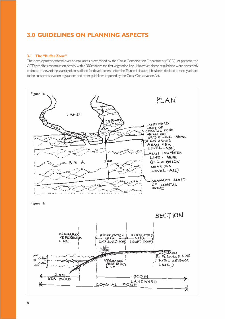
3.1 The “Buffer Zone”The development control over coastal areas is exercised by the Coast Conservation Department (CCD). At present, theCCD prohibits construction activity within 300m from the first vegetation line . However, these regulations were not strictlyenforced in view of the scarcity of coastal land for development. After the Tsunami disaster, it has been decided to strictly adhereto the coast conservation regulations and other guidelines imposed by the Coast Conservation Act.
3.0 GUIDELINES ON PLANNING ASPECTS
Figure 1a
Figure 1b
9
The Coast Conservation Act requires the CCD to develop a Coastal Zone Management Plan (CZMP) every 5 years. The currentlyapplicable CZMP was developed in 2004 (CZMP, 2004) and approved by the cabinet of Ministers in 2005. However the previousversion of the CZMP (CZMP, 1997 approved by the Cabinet of Ministers on 10 September 1997) contains valuable references to thecoastal zone and much of this information (if not superceded by the CZMP 2004) remains valid.
The Coast Conservation Act defines “coastal zone” thus (see Figure 1a/b for illustrations):“Area lying within a limit of three hundred meters landward of the mean high water line and a limit of two kilometersseaward of the mean low water line, and in the case of rivers, streams, lagoons or any other body of water connected tothe sea either permanently or periodically, the landward boundary shall extend to a limit of two kilometers measuredperpendicular to the mean low water line.”
All developmental activities within the coastal zone require a permit (either from the Director, CCD or the respectiveDivisional Secretaries – see Table 1).
Figure 1b shows a portion of the coastal zone considered critical for the well-being of the coastal eco-system. This areais divided into two: “reservation area” (no build zone) and “restricted area” (soft zone). As indicated in page 4-5, some developmentactivity is allowed within the “restricted area.”
The seaward reference line of this sensitive area is fixed (i.e. 0.6meter above the mean sea level). The landward referenceline varies, according to the sensitivity of a given coastal area to sea erosion and other natural hazards. The CZMP (1997)has divided the coast of Sri Lanka into 70 segments and has proposed a varying landward reference line, depending on therisk factors mentioned above (See Appendix I for further details).
Following the tsunami disaster in December 2004, the landward reference line has been determined as follows:i. 100 m landwards from the mean high water line in the following districts – Killinochchi, Puttlam, Gampaha, Colombo,
Kalutara, Galle, Matara, Hambantota;ii. 200 m landwards from the mean high water line in the coastal belt within the Jaffna, Mullaitivu, Trincomalee, Batticaloa
and Ampara Districts.
Readers are requested to consult the CZMP (1997 and 2004) for further details on the coastal segments, their risk factors(Table 6.2, p. 86ff of CZMP, 1997 – See also Appendix I of this document), prohibited areas and the procedure to befollowed when requesting development permits from the CCD (refer, Figure 8.2, p. 8-19 of CZMP, 2004).
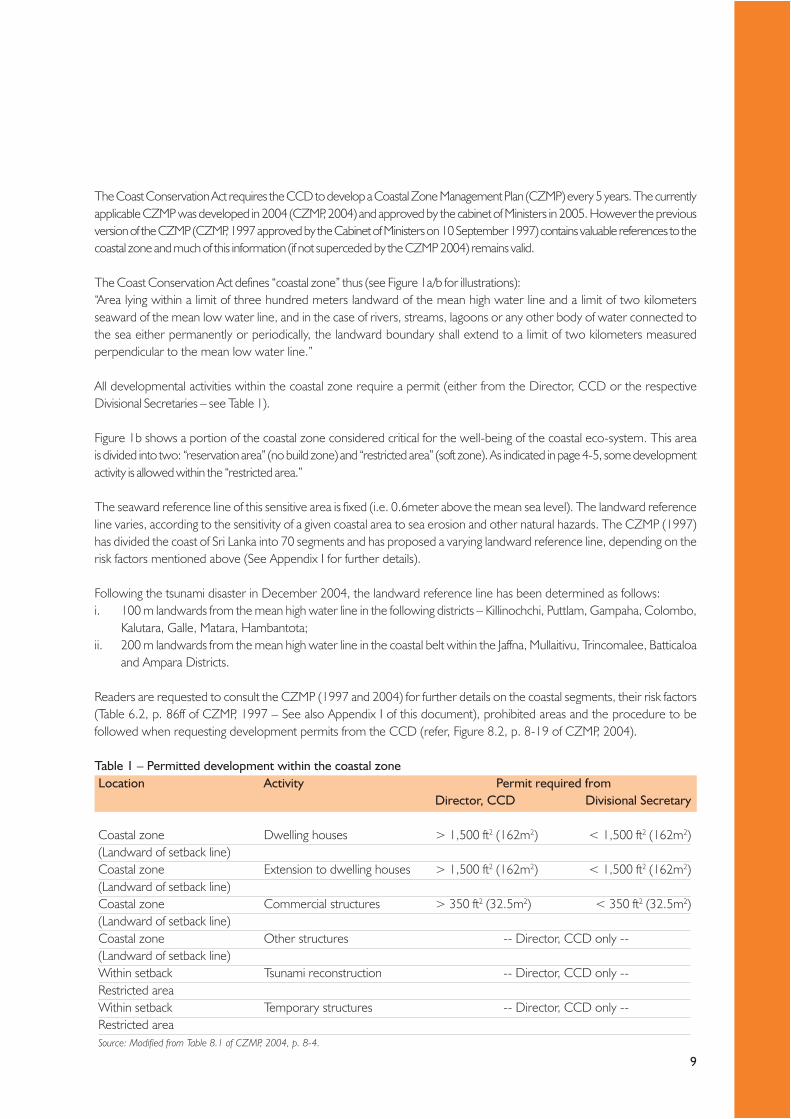
Table 1 – Permitted development within the coastal zoneLocation Activity Permit required from
Director, CCD Divisional Secretary
Coastal zone Dwelling houses > 1,500 ft2 (162m2) < 1,500 ft2 (162m2)(Landward of setback line)Coastal zone Extension to dwelling houses > 1,500 ft2 (162m2) < 1,500 ft2 (162m2)(Landward of setback line)Coastal zone Commercial structures > 350 ft2 (32.5m2) < 350 ft2 (32.5m2)(Landward of setback line)Coastal zone Other structures -- Director, CCD only --(Landward of setback line)Within setback Tsunami reconstruction -- Director, CCD only --Restricted areaWithin setback Temporary structures -- Director, CCD only --Restricted areaSource: Modified from Table 8.1 of CZMP, 2004, p. 8-4.

10
3.2 Selection of siteIn selecting sites for housing development in the coastal belt, it is to be kept in mind that under no circumstances buildings shouldbe constructed within the reservation area. Within the restricted area, housing development may be permitted by the CCD, if theland is at least 3m above the Mean High Water Line. Restrictions in terms of the extent of the individual housing units may apply (seeTable 1).
The other statutory provision in site selection is that the site should be such that buildings could be located on stablefoundations on soil strata having no susceptibility for liquefaction.
3.3 Planning of settlementsThe primary requirement in settlement planning is to ensure the proposed housing development is in an area demarcatedfor residential land use (For tsunami housing, the settlements should be planned so that the minimum floor area of eachdwelling unit is at least 46.5m2 – 500ft2). A schematic settlement plan fulfilling these criteria must be submitted for preliminaryplanning clearance from the relevant local authority and/or the UDA before proceeding with detailed design, so as toaccommodate the statutory requirements of such authorities.
In the case of multi-site housing development, the developer should consult the relevant planning authority in the respectiveareas (MC, UC or Pradeshiya Sabha) for obtaining planning approval.
The legal requirement for settlement planning for a development consisting of 20 or more dwellings (individual housingunits, semi-detached houses or condominium apartments) is given in Table 2.
Table 2 – Settlement planning requirements by the UDAf
Utilization Coverage of Settlement Land
Housing – Neighborhood facilities 65% (Max.)Common Area 10% (Min.)Road, Streets, footpath and drains 20% (Min.)Public and semi public (social infrastructure) 05% (Min.)
3.4 Plot size and coverageTable 3 shows the plot size and general requirements for individual houses in areas where pipe-borne water supply andsewage disposal are not available.
Table 3 – Plot size requirements by the UDAf
Element General Requirements
Plot size (individual dwellings)b 10 – 20 perchesa (253 – 506 m2)Plot size for town housed 6 – 12 perchesc (152 – 303 m2)Building line Depends on the road size and the category of the road.
If not available, assumed to be 12.5 m (40’-0” ft)from the center of the road
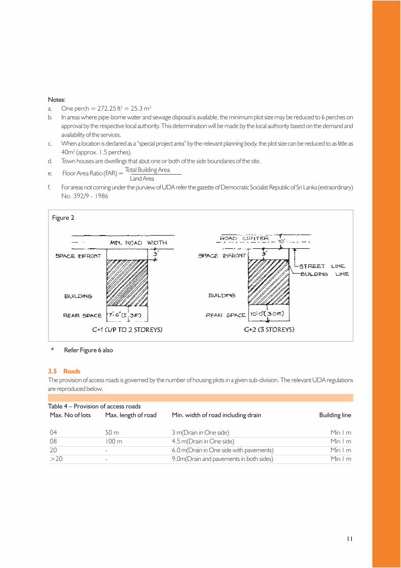
Street Line Refer Figure 2Rear Space Refer Figure 2Front Space Refer Figure 2Floor Area Ratio (FAR)e 1.5 (Max.)
3.0 GUIDELINES ON PLANNING ASPECTS CONTD.
11
Notes:a. One perch = 272.25 ft2 = 25.3 m2
b. In areas where pipe-borne water and sewage disposal is available, the minimum plot size may be reduced to 6 perches onapproval by the respective local authority. This determination will be made by the local authority based on the demand andavailability of the services.
c. When a location is declared as a “special project area” by the relevant planning body, the plot size can be reduced to as little as40m2 (approx. 1.5 perches).
d. Town houses are dwellings that abut one or both of the side boundaries of the site.
e. Floor Area Ratio (FAR) = Total Building AreaLand Area
f. For areas not coming under the purview of UDA refer the gazette of Democratic Socialist Republic of Sri Lanka (extraordinary)No. 392/9 - 1986
3.5 RoadsThe provision of access roads is governed by the number of housing plots in a given sub-division. The relevant UDA regulationsare reproduced below.
Table 4 – Provision of access roadsMax. No of lots Max. length of road Min. width of road including drain Building line
04 50 m 3 m(Drain in One side) Min 1 m08 100 m 4.5 m(Drain in One side) Min 1 m20 - 6.0 m(Drain in One side with pavements) Min 1 m>20 - 9.0m(Drain and pavements in both sides) Min 1 m
Figure 2
* Refer Figure 6 also

12
Figure 4
Figure 3
Figure 5
3.0 GUIDELINES ON PLANNING ASPECTS CONTD.
13
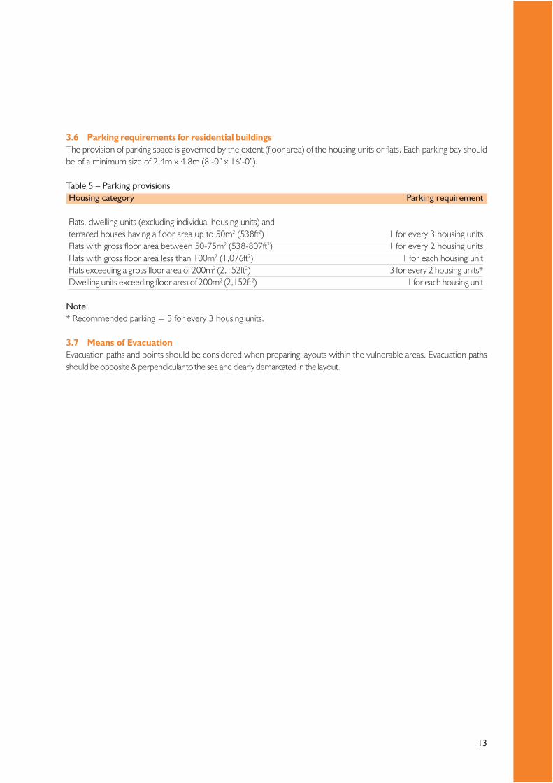
3.6 Parking requirements for residential buildingsThe provision of parking space is governed by the extent (floor area) of the housing units or flats. Each parking bay shouldbe of a minimum size of 2.4m x 4.8m (8’-0” x 16’-0”).
Table 5 – Parking provisionsHousing category Parking requirement
Flats, dwelling units (excluding individual housing units) andterraced houses having a floor area up to 50m2 (538ft2) 1 for every 3 housing unitsFlats with gross floor area between 50-75m2 (538-807ft2) 1 for every 2 housing unitsFlats with gross floor area less than 100m2 (1,076ft2) 1 for each housing unitFlats exceeding a gross floor area of 200m2 (2,152ft2) 3 for every 2 housing units*Dwelling units exceeding floor area of 200m2 (2,152ft2) 1 for each housing unit
Note:* Recommended parking = 3 for every 3 housing units.
3.7 Means of EvacuationEvacuation paths and points should be considered when preparing layouts within the vulnerable areas. Evacuation pathsshould be opposite & perpendicular to the sea and clearly demarcated in the layout.
14
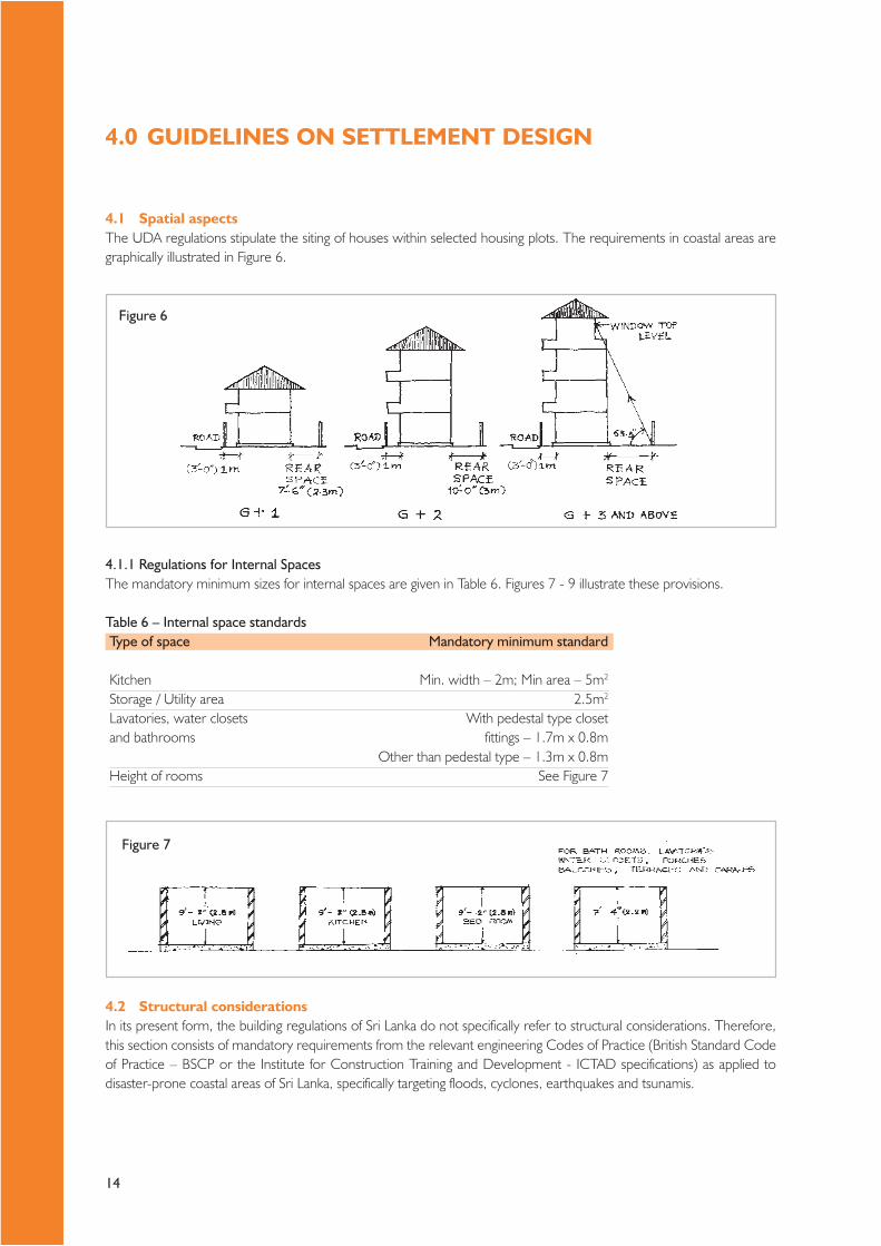
4.1 Spatial aspectsThe UDA regulations stipulate the siting of houses within selected housing plots. The requirements in coastal areas aregraphically illustrated in Figure 6.
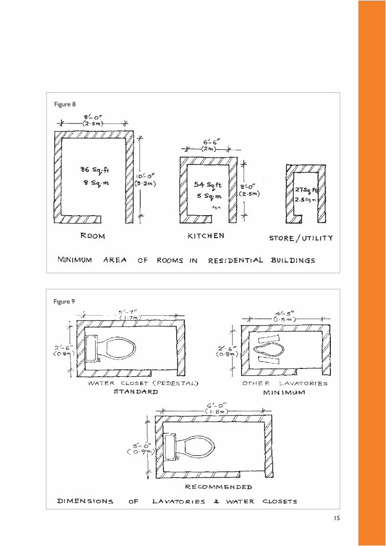
4.1.1 Regulations for Internal SpacesThe mandatory minimum sizes for internal spaces are given in Table 6. Figures 7 - 9 illustrate these provisions.
Table 6 – Internal space standardsType of space Mandatory minimum standard
Kitchen Min. width – 2m; Min area – 5m2
Storage / Utility area 2.5m2
Lavatories, water closets With pedestal type closetand bathrooms fittings – 1.7m x 0.8m
Other than pedestal type – 1.3m x 0.8mHeight of rooms See Figure 7
4.2 Structural considerationsIn its present form, the building regulations of Sri Lanka do not specifically refer to structural considerations. Therefore,this section consists of mandatory requirements from the relevant engineering Codes of Practice (British Standard Codeof Practice – BSCP or the Institute for Construction Training and Development - ICTAD specifications) as applied todisaster-prone coastal areas of Sri Lanka, specifically targeting floods, cyclones, earthquakes and tsunamis.
4.0 GUIDELINES ON SETTLEMENT DESIGN
Figure 6
Figure 7
15
Figure 8
Figure 9

16
4.2.1 General principles of design to withstand natural disastersIn addition to the normal task of designing a building to prevent it from falling down under gravity, buildings subject tocyclones, flooding and earthquakes must be prevented from being pushed sideways and/or lifted upwards. In general, thiscalls for the introduction of steel reinforcement into the building envelope. For coastal buildings not subject to cyclones,flooding and earthquakes, steel reinforcement is best avoided, as the introduction of steel not only increases cost, but alsointroduces the inevitable onset of corrosion in due course.
Contrary to conventional wisdom, it is desirable to increase the weight of structures in order to resist cyclones andflooding.
Earthquakes can occur anywhere, but their intensity is low in Sri Lanka and hence moderate provision for earthquakesmay be sufficient. Cyclones are frequent on the North and East coast and therefore design against uplift is essential, notonly near the coast, but probably in the entire Eastern and Northern Provinces. The flooding considered here is mainlycoastal flooding.
Any building within 500m in general and up to 2km along the East Coast and/or 3m elevation from mean sea level shouldbe designed according to these guidelines.
Buildings designed to withstand natural disasters in the coastal belt of Sri Lanka must adhere to the following principles:i. Building must be held down to the foundation. Hence at least 4 reinforced concrete columns at the four corners are
essential.A 150mm x 150mm corner column can be constructed inside one half of a 200 mm thick hollow block into which concreteis poured after piercing one of the 150 mm x150mm hollows in the block. Blocks in alternate courses placed in mutuallyperpendicular directions will have a common opening 150mm x 150mm or so (Figure 10).Alternatively, the concrete could be poured in after constructing the walls, but GI stirrups should be placed at every4th course in the masonry to stick into the column (Figure 11). For wall lengths exceeding 6m, an additional intermediatecolumn along that wall should be introduced. These columns (and the pad footings described below), are essentialfor buildings within the coastal belt subject to flooding. They are desirable for resistance against earthquakes andcyclones.
ii. Below ground level, the column should be of 200mm x 200mm size and be connected with a concrete pad footingof size 750mm x 750mm x 150mm, with the column reinforcement bent at least 300 mm into the footing. The footingreinforcement can be 6 nos. 10mm tor steel in each direction. The formation level of the footing should be at least1.0 m-1.5m below ground level (Figure 12).
iii. The columns (if provided) and all other walls should be connected together at the lintel level. This lintel beam can be of100mm depth with just two 10mm tor steel bars (Figure 44). This will ensure that frame action and load transfer from wallsto frames can take place in the presence of columns. Even if there are no columns, the lintel will tie walls together and improvetheir resistance to earthquakes and cyclones. Hence, this simple lintel beam is probably the single most important disaster-mitigation element, as it will provide some resistance against all natural disasters.
iv. The reinforcement from the columns should be connected to the wall plate of the roof.The slope of the roof should be 22-30o to minimize wind uplift. Ideally roofing sheets should be used, fixed atintervals of not greater than 1.5m in both directions to the underlying roof timber. This provision is important forcyclone prone areas. If columns have not been used, single 10mm steel bars encased in concrete of cross section100mm x 100mm (minimum) should be connected to the wall plates on the one hand and the lintel beam on theother. The bars should be bent into the lintel beam (prior to concreting the beam) for a length of 450mm. If aconcrete roof is being used, columns are essential (in addition to the lintel beam).
v. For flooding and cyclonic conditions, walls should be made as heavy as possible; if hollow blocks are used theyshould be at least 200mm thick, and if 100mm thick walls are used, they should be of solid block work or brick work.Where flooding and cyclonic conditions do not prevail, minimizing the wall weight is desirable.
4.0 GUIDELINES ON SETTLEMENT DESIGN CONTD.

17
Figure 10
Figure 11
Figure 12

18
vi. Good quality materials should be used, especially if excessive loads may have to be resisted. For binding mortar, the mixproportions should not be leaner than 1:6 cement:sand. For making cement blocks, the proportions should be 1:10(cement:sand or quarry dust). It could also be 1:7:10 (cement : sand : 6-8mm aggregate chips). Cement blocks shouldideally be used only after 1-2 months after casting, to allow for shrinkage.The quality of concrete should be at least Grade 20 (i.e. cement : sand : coarse aggregate = 1:2:4). Use Grade 25for multi-storey buildings near coast. This can be achieved using a 1:1½:3 mix (cement : sand : coarse aggregate) orusing a Grade 20 concrete with 15% extra cement (see, SSESL, 2005: 2-3ff).
4.2.2 FoundationsThe essential requirements of foundations to withstand typical coastal disasters are given below (see also, Figure 13a and b):
i. Buildings can have shallow foundations on stiff sandy soil;ii. When there is risk of scouring due to storm surge, a minimum depth of foundation 1.0 m below natural ground level should
be provided in the coastal zone;iii. Where a building is constructed on stilts, the stilts should be properly braced in both the principal directions. This will
provide stability to the complete building under lateral loads. Knee braces are preferable to full diagonal bracing so asnot to obstruct the passage of floating debris during tidal surge/tsunami;
iv. The wall foundation should have a width of two and half times the thickness of wall (not less than 0.6m in any event). Footingsshould be constructed in stone or cement blocks, and not in brick work;
v. The plinth height should not be less than 0.45 m above natural ground level or as per topography requirement;vi. The columns should be founded on pad footings.
Figure 13A
Figure 13B
4.0 GUIDELINES ON SETTLEMENT DESIGN CONTD.

19
Table 7 – Minimum width of load bearing foundations for single and two-storied housesType of sub soil Condition of Min. width in mm (in) for total load
sub soil in kN/m15 kN/m 30 kN/m
Rock - Equal to width of wallGravel Compact 150 (6”) 300 (12”)Sand Compact 150 (6”) 300 (12”)Clay Stiff. 150 (6”) 300 (12”)Sandy Clay Stiff. 150 (6”) 300 (12”)Clay Firm 175 (7”) 350 (14”)Sandy Clay Firm 175 (7”) 350 (14”)Gravel LooseSand Loose 300 (12”) 600 (24”)Silt Sand LooseClay Sand LooseSilt Very SoftClay Very Soft 425 ( 17”) 850 ( 34”)Sandy Clay Very SoftSilt Clay Very Soft
Notes:1 Width of foundation should be greater than the minimum given in the Table, in order to minimize the adverse effects
due to tree roots where necessary.2 Loads on walls of domestic buildings are unlikely to exceed 30 kN/m for 2 storey and 15 kN for single storey.
4.2.3 Two and multi-storied framed structuresTypes and sizes of foundations mainly depend on the load transferring method to soil (through column or walls) and thebearing capacity of soil.
Concrete frame with infill walls above first floor with columns having lateral bracings at ground level is recommended. Insuch buildings ground floor should be structurally detailed for seismic resistance.
4.2.4 Wallsi. All external walls or wall panels must be designed to resist the out of plane lateral pressure adequately. For this, the
walls should be sufficiently buttressed by transverse walls.ii. A small building enclosure with properly interconnected walls is ideal. Buildings having long walls should be avoided.iii. It is necessary to reinforce walls by means of at least one horizontal reinforced concrete band at lintel level.iv. The thickness of the load bearing and/or external walls should not be less than 200mm; other walls can be 100mm
thick. If external walls are 100mm thick, they must be of solid cement blockwork or brickwork.v. Since tensile and shear strength are important for lateral resistance of masonry walls, use of mud or very lean
mortars should be avoided. A mortar mix leaner than 1:6 cement : sand should never be used.vi. For achieving full strength of masonry, the usual bonds specified for masonry should be followed so that the vertical
joints are broken properly from course to course (Figure 14).vii. Concrete columns (200mm x 200mm) founded as pad footings must be provided at least at the four corners of the
building. These columns should be connected by a continuous lintel beam.viii. The free-standing wall height should not be greater than 3m.
20
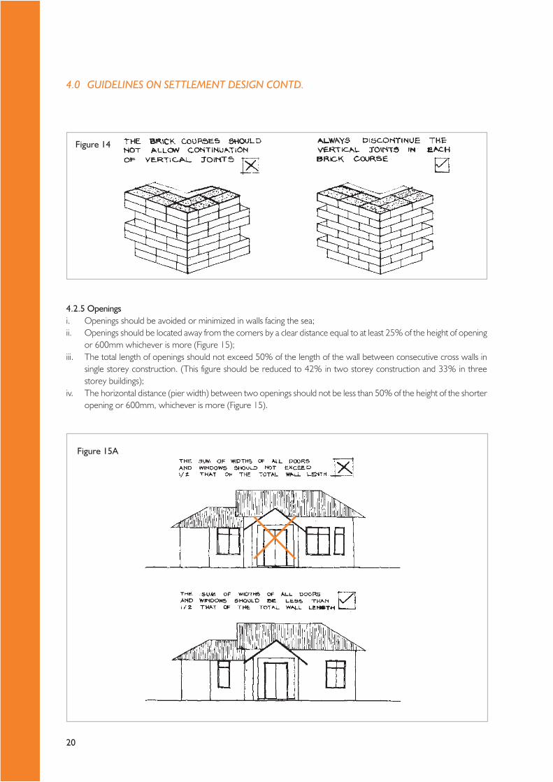
4.2.5 Openingsi. Openings should be avoided or minimized in walls facing the sea;ii. Openings should be located away from the corners by a clear distance equal to at least 25% of the height of opening
or 600mm whichever is more (Figure 15);iii. The total length of openings should not exceed 50% of the length of the wall between consecutive cross walls in
single storey construction. (This figure should be reduced to 42% in two storey construction and 33% in threestorey buildings);
iv. The horizontal distance (pier width) between two openings should not be less than 50% of the height of the shorteropening or 600mm, whichever is more (Figure 15).
Figure 14
Figure 15A
4.0 GUIDELINES ON SETTLEMENT DESIGN CONTD.
21
Figure 15B
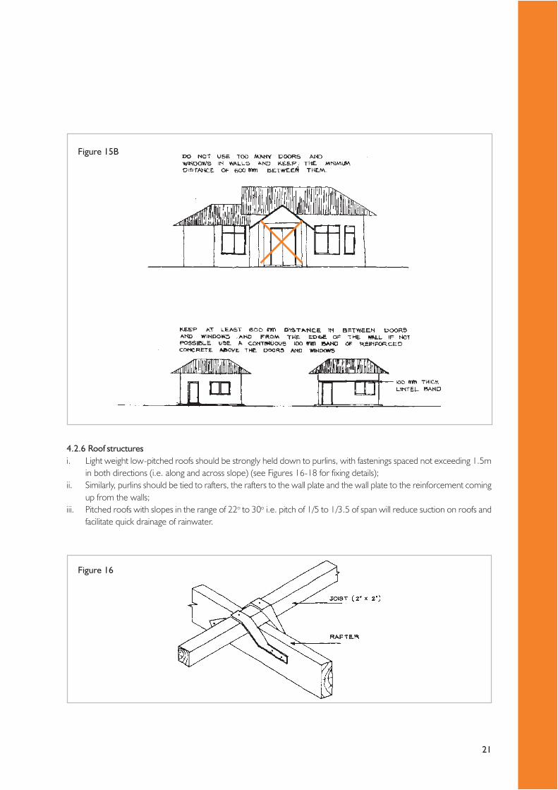
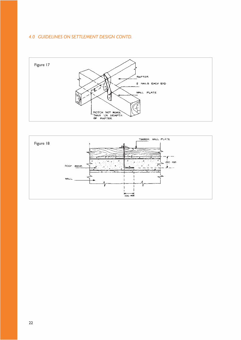
4.2.6 Roof structuresi. Light weight low-pitched roofs should be strongly held down to purlins, with fastenings spaced not exceeding 1.5m
in both directions (i.e. along and across slope) (see Figures 16-18 for fixing details);ii. Similarly, purlins should be tied to rafters, the rafters to the wall plate and the wall plate to the reinforcement coming
up from the walls;iii. Pitched roofs with slopes in the range of 22o to 30o i.e. pitch of 1/5 to 1/3.5 of span will reduce suction on roofs and
facilitate quick drainage of rainwater.
Figure 16
22
Figure 17
Figure 18
4.0 GUIDELINES ON SETTLEMENT DESIGN CONTD.

23
5.1 Water supplyAll housing settlements should have access to safe drinking water, either by a piped water supply system or by a protectedwell or from ground water (tube well). The supply system must have the concurrence from the water supply authority(NWS&DB or local authorities) in terms of quantity and quality of the supply.
Pipe systems should be designed for carrying capacity (flow) and pressure conditions. Thus, assessment of the waterdemand and the requirement of pressure are the basic considerations in designing a water supply system. When calculatingthe quantity of water required to a settlement or a storied apartment complex, the recommended per capita consumptionis 140 liters per person per day.
The following are suggested as the basic requirements for a satisfactory water supply system:i. The pressure head available (residual pressure) at any point of the distribution system should be more than 5m;ii. The minimum velocity in a pipe line should not be less than 0.6m/s to prevent deposition of silt;iii. Air valves and scour valves should be provided at high and low points respectively;iv. A minimum of one day’s requirement must be stored at site;v. When ground and elevated storage is provided, the common practice is to provide 70% of the total storage as
ground storage and the balance as elevated storage;vi. Pipe line laid in flat terrain should have a minimum gradient of 1 in 500 to drain and expel air in the line;vii. When laying pipe lines in trenches, the minimum trench width should be d+300mm, where ‘d’ is the diameter of
the pipe (in mm). The minimum earth cover for buried pipes should be 0.8m (normal conditions) and 1.0m (inroadways). Water and sewer pipes should never be laid in the same trench. Water pipes should always be laid abovesewer/drainage pipes;
viii. The minimum horizontal clearance of any sewer line should be 3m and the bottom of the water line should be atleast 0.5m above the top of the sewer line.
5.2 Electricity5.2.1 Power supply systemDepending on the location of the proposed housing development, consumers will have to approach either the CEB orLECO to obtain new service connections. Upon receipt of a request for the supply of electricity, the supply authority willestimate the cost of infrastructure provisions (construction work connected with cabling as well as equipment such astransformers, if needed).
Electricity required for community settlements can be obtained from power supply authorities by using one of the followingmethods.i. For few houses – from the existing single phase or 3 phase lineii. For a large settlement (more than 24 nos. housing units) – from the existing high voltage lines (33kv & 11 kv) through a
transformer installed within the premises of the project site.
The entire on-site access roads, footpaths, streets, etc., should be illuminated with street lighting.
Wherever possible, provide underground cables for electricity supply to avoid damage due to falling of overhead cablelines on houses and the public during high wind. Underground cabling will also help avoid illegal connections.
The decision to locate transformers should involve consultations with the residents. In any event, transformers should belocated so as to keep the minimum distance specified by CEB between the transformer and the nearest house. It is advisable toconsult the CEB area office to get this information.
No construction is allowed under any transmission line passing through a proposed project site. A horizontal distance of2m (6’- 0”) from either side of the transmission line should be reserved as a service reservation for the transmission line.
5.0 GUIDELINES ON PROVISION OF PHYSICALINFRASTRUCTURE

24
5.2.2 Internal distribution systemThe internal distribution system should comply with the latest IEE regulations published for internal wiring of buildings.Select the most suitable method of wiring out of the three methods indicated below.i. Concealed conduits buried in slabs and walls;ii. Surface mounted PVC casings and boxes;iii. Surface mounted PVC conduits/casing.
Items and materials selected should be in compliance with the latest BS/SLS or their equivalent. The correct type ofprotective devices (MCB & ELCB) must be selected for the distribution board to protect the system against overload,short circuit and earth leakage/electric shock. Care must be taken to ensure that the correct type /size of cables are selected so asto reduce construction cost and to avoid abnormal heating / fire hazards.
The request for type of supply (15A/30A single phase or 15A/30A 3-phase) should be made according to therecommendations shown in Table 8.
Table 8 – Recommended CEB/LECO service connectionsSystem MAXIMUM NO. OF POINTS TO BE USED
Lamps & 5A Socket 15A Socket Exhaust fan, RecommendedFans outlets outlets shaver sockets, power supply
electrical bells
Type 1 8 4 - 1 * Single phase 15AType 2 25 8 - 2 Single Phase 30AType 3 25 7 1 3 Single phase 30AType 4 25 5 2 3 * Three phase 15AType 5 75 21 3 3 Three phase 30 A
* could be obtained only for Colombo metropolitan areaNote:15 Amp socket outlets not recommended for 15 Amp service (Type 1)15 Amp sockets 02 Nos. are not recommended for 30 Amp service (Type 2)
5.2.3 Lightning conductorsFollowing factors will necessitate the installation of lightning conductors in buildings:i. Project site situated in a relatively isolated area;ii. Project site located in a lightning-prone area;iii. Houses / Housing blocks proposed to be constructed will be the tallest objects in the area;iv. Risk indicators calculated for the buildings are above the standard marginal values.
If needed, the most suitable system is the conventional type (Franklyn rod) as opposed to the more expensive systemssuch as an early streamer emission system. No radioactive type is allowed (see, ICTAD publication SCA /8, Aug. 2000).
The applicable specification for the system should be the British Standard (BS 6651), Code of Practice (CP 326) or SLSIpublication : 2004.
5.0 GUIDELINES ON PROVISION OF PHYSICAL INFRASTRUCTURE CONTD.

25
Table 9 – Recommended installation heightsElectrical installation Recommended height
of installation(mm above floor level)
Switches 1350Socket outlet (low levels) 300Socket outlet (Kitchen area/ pantry) 1200Pendent Lamp 2400Florescent Fittings 2400Ceiling fans 2400Consumer Units 2100Wall Bracket Lamps 2250
IMPORTANT NOTES1. All lamps with metal parts should be earthed.2. All florescent lamps should be of power factor corrected type.3. All cables shall be PVC/PVC/Cu except earth wire which could be PVC/Cu. PVC/PVC/Cu - PVC insulated, PVC
sheathed cables with copper conductor [Rigid/strained, single core or twin multi core]. PVC/Cu - PVC insulatedCopper conductor without sheath.
3. Lamps, fan circuits and 5 Amp socket outlets shall be wired with 1/1.13 mm (1mm 2) cable and 7/0. 67mm (2.5mm2)earthwire.
4. Switches, socket outlets and distribution board should be flush or surface mounting type.
Table 10 – Sub-circuit arrangementCircuit Type No. of points per circuit M.C.B. Rating
Lamps, fans, bells 8 6 A5 A. Plugs 2 10 A15 A Plugs 1 16 ARing circuits (with 13 A plugs) Any number 16/20 A
5.3 TelecommunicationTelecommunication is a fast changing area of infrastructure that has seen unprecedented growth in the recent past. Theprimary provider of telecommunication services (Dept. of Telecommunications) was privatized in 1997 (Sri Lanka Telecom)and several privately owned fixed and wireless local loop operators are present in Sri Lanka. With the introduction ofCode Division Multiple Access (CDMA) technology, telecommunication facilities can be obtained virtually over the counter.
The only restriction the present guideline wishes to point out is that no telecommunication transmission tower is allowedwithin housing project sites. It is further recommended that the distance from a transmission tower to a nearby buildingshould be twice the height of the tower.
5.4 Waste water disposalWastewater can be treated in three different ways:i. On-plot waste water disposal;ii. On-site waste water treatment and disposal;iii. Off-site waste water treatment and disposal.

26
5.4.1 On-plot waste water disposal (Toilet waste included)The primary mechanism of on-plot waste water disposal system is a septic tank followed by a soakage pit (either pre-castor cast in situ). Pre cast septic tanks can also be used as an alternative for the cast in situ types. Popular sizes of the tanksavailable in Sri Lanka for a single family unit consisting 5 members are:
0.6 m (2’-0”) Diameter and 2.4 m (8’-0”) length;1.0 m (3’-3”) Diameter and 2.4 m (8’-0”) length.
High absorption capacity in the soil and low water table are the prime requirements to introduce this type of soakage pits.
Other systems of on-plot waste water disposal are, double pit compost toilets and a pour flush pit latrine.
5.4.2 On-site waste water disposalThe primary components of an on-site system are, a Septic tank followed by an anaerobic biological filter and soakage pit,soakage drain field, evaporation mounds or discharge into an open water body after purification. The NHDA possess vastexperience in designing these types of wastewater disposal methods for medium density housing settlements (60 housing unitsper acre) and walkup apartment complexes island-wide. (Design assistance in this connection can be provided by the NHDA onrequest. See Figure 20 for typical details).
Compacted water treatment plants such as oxidation ponds, package treatment plants, and aerated lagoons, too can beselected to suit the site conditions.
If the compacted water treatment plants are planned to be used at site, clear distance (buffer zone) from the housing unitsare to be maintained as indicated in the respective plant specifications. (As a rule of thumb, the plant should be locatedapproximately 30 m away from the nearest housing unit).
Selection criteria of the above systems are governed by the following factors.i. Population density;ii. Volume of waste water produced;iii. Presence of shallow wells susceptible to waste water pollution;iv. Soil permeability;v. Unit cost of waste water collection;vi. Socio economic and cultural considerations.
Figure 19
5.0 GUIDELINES ON PROVISION OF PHYSICAL INFRASTRUCTURE CONTD.
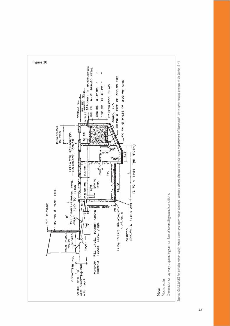
27
Figure 20
Sour
ce:
GU
ILD
LIN
ES fo
r po
rtabl
e wa
ter
supp
ly, w
aste
wat
er a
nd s
torm
wat
er d
rain
age,
dom
estic
sew
age
disp
osal
and
sol
id w
aste
man
agem
ent
of d
esign
ated
lo
w in
com
e ho
usin
g pr
ojec
ts in
Sri
Lank
a, P
. 41
Not
e:N
ot to
scale
Dim
ensio
ns m
ay va
ry d
epen
ding
on
num
ber o
f use
rs &
grou
nd co
nditio
ns
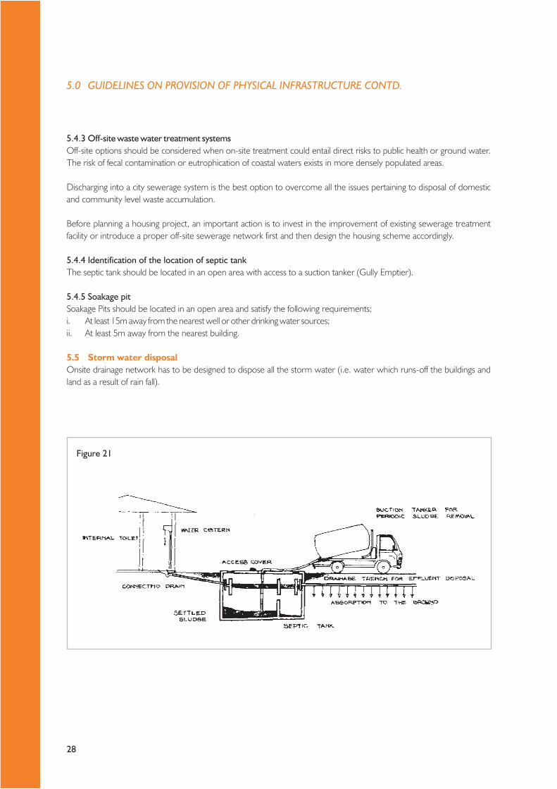
28
5.4.3 Off-site waste water treatment systemsOff-site options should be considered when on-site treatment could entail direct risks to public health or ground water.The risk of fecal contamination or eutrophication of coastal waters exists in more densely populated areas.
Discharging into a city sewerage system is the best option to overcome all the issues pertaining to disposal of domesticand community level waste accumulation.
Before planning a housing project, an important action is to invest in the improvement of existing sewerage treatmentfacility or introduce a proper off-site sewerage network first and then design the housing scheme accordingly.
5.4.4 Identification of the location of septic tankThe septic tank should be located in an open area with access to a suction tanker (Gully Emptier).
5.4.5 Soakage pitSoakage Pits should be located in an open area and satisfy the following requirements;i. At least 15m away from the nearest well or other drinking water sources;ii. At least 5m away from the nearest building.
5.5 Storm water disposalOnsite drainage network has to be designed to dispose all the storm water (i.e. water which runs-off the buildings andland as a result of rain fall).
Figure 21
5.0 GUIDELINES ON PROVISION OF PHYSICAL INFRASTRUCTURE CONTD.

29
Storm water drains are of two different types:i. Site drains (primary drains);ii. Off-site drains (secondary drains).
Site drains are constructed on the side/s of internal roads, foot paths, streets, backyards etc., and convey the accumulatedwater into the secondary drains, which sometimes disposes water into a near-by stream or canal. Most of the secondarydrains are off-site drains, the maintenance of which comes under the purview of the respective Local Authority. SeeFigures 22-29 for further details.
Figure 23
Figure 22
Figure 24

30
Figure 25
Figure 26
Figure 27
5.0 GUIDELINES ON PROVISION OF PHYSICAL INFRASTRUCTURE CONTD.

31
Figure 28
Figure 29
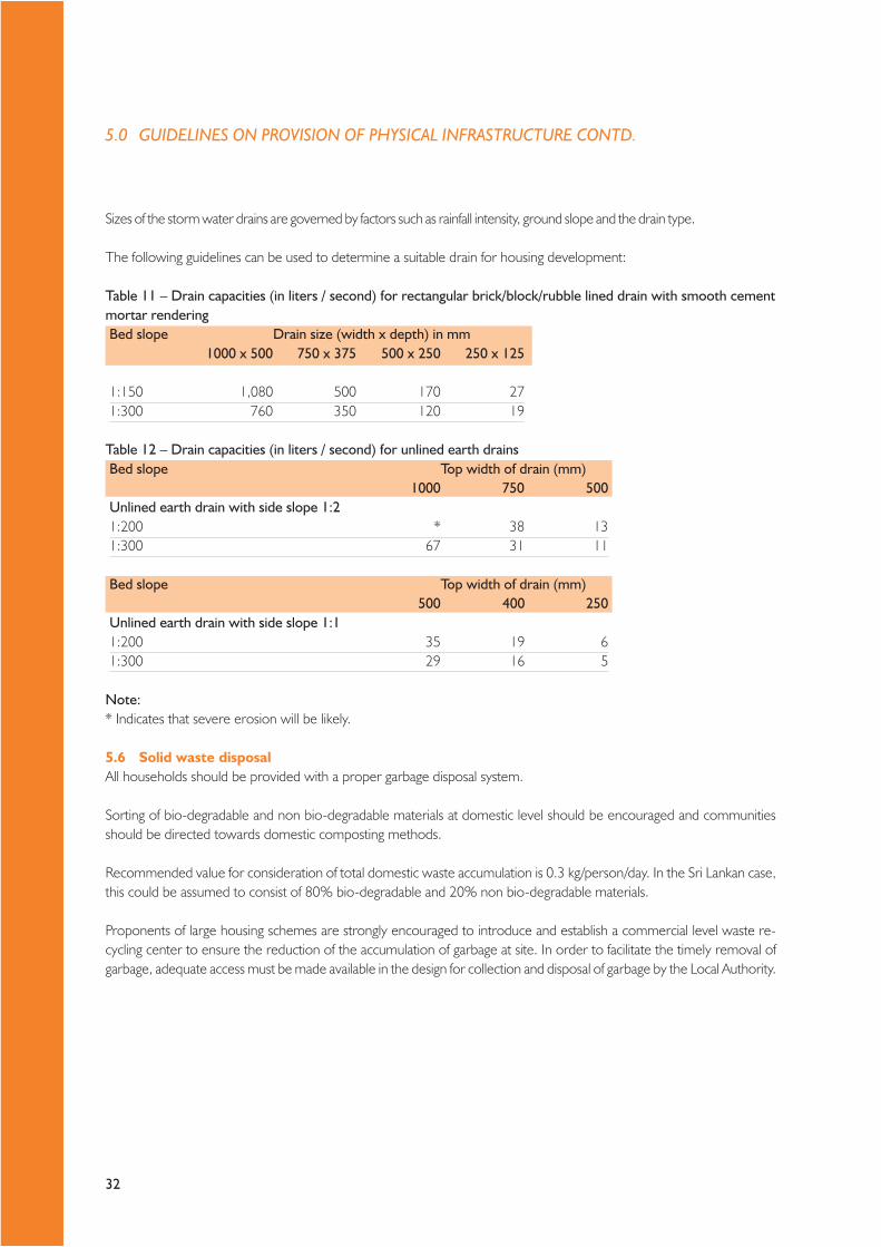
32
Sizes of the storm water drains are governed by factors such as rainfall intensity, ground slope and the drain type.
The following guidelines can be used to determine a suitable drain for housing development:
Table 11 – Drain capacities (in liters / second) for rectangular brick/block/rubble lined drain with smooth cementmortar renderingBed slope Drain size (width x depth) in mm
1000 x 500 750 x 375 500 x 250 250 x 125
1:150 1,080 500 170 271:300 760 350 120 19
Table 12 – Drain capacities (in liters / second) for unlined earth drainsBed slope Top width of drain (mm)
1000 750 500Unlined earth drain with side slope 1:21:200 * 38 131:300 67 31 11
Bed slope Top width of drain (mm)500 400 250
Unlined earth drain with side slope 1:11:200 35 19 61:300 29 16 5
Note:* Indicates that severe erosion will be likely.
5.6 Solid waste disposalAll households should be provided with a proper garbage disposal system.
Sorting of bio-degradable and non bio-degradable materials at domestic level should be encouraged and communitiesshould be directed towards domestic composting methods.
Recommended value for consideration of total domestic waste accumulation is 0.3 kg/person/day. In the Sri Lankan case,this could be assumed to consist of 80% bio-degradable and 20% non bio-degradable materials.
Proponents of large housing schemes are strongly encouraged to introduce and establish a commercial level waste re-cycling center to ensure the reduction of the accumulation of garbage at site. In order to facilitate the timely removal ofgarbage, adequate access must be made available in the design for collection and disposal of garbage by the Local Authority.
5.0 GUIDELINES ON PROVISION OF PHYSICAL INFRASTRUCTURE CONTD.
Section II – BEST PRACTICE GUIDE
34
6.1 Post-tsunami observationEven a cursory observation of the structures affected by the tsunami waves would reveal that the most severely damagedstructures are those constructed close to the sea. Although the degree of damage correlates to the magnitude of wavepressure, factors such as structural form, shape of buildings and orientation in relation to the wave direction also hadsignificant bearing on the extent of damage.
Building with load-bearing walls, especially those that are perpendicular to the direction of the waves had shown lessresistance to the ocean waves and had been completely destroyed, whereas framed structures with reinforced concretecolumns and beams as well as load bearing walls that are parallel to the direction of the waves have shown a higherdegree of resistance.
While the extent and severity of damage provides clues towards best practice, the re-construction exercise itself couldbenefit from best practices developed elsewhere in post-disaster renewal and rejuvenation. On the one hand, the socialaspects of re-construction, especially an inclusive and participatory approach has proved to be successful in many contexts.On the other, post-disaster scenarios often provide a golden (if perverse!) opportunity to “design with nature” that notonly will withstand future disasters well, but are also cost-effective.
This section is a distillation of the collective wisdom of several key stakeholders involved in post-disaster housing in termsof social, environmental and technological aspects. It is hoped that the best practices advocated here will re-kindle theimagination of all players in the Sri Lankan post-disaster housing scene. It is also hoped that the wisdom contained hereinwill continue to grow even as greater experience in these matters is accumulated.
6.2 Best social practices – Community centered planningRebuilding communities and involving them in the early stages of shelter programming is essential. Providing a “dignifiedliving” is first of all a matter of enabling the people to make appropriate choices themselves and set their priorities at allstages of project implementation.
Lack of substantive, effective and continued community involvement carries great risks both to the community and to thesuccess of a housing project. The risks to the community (or families within the community) of ineffective communityinvolvement include, the creation of structures and site arrangements that do not satisfy their needs or desires; and lack asense of ownership of the asset.
This can result in community unrest that delays or challenges the completion of the project; un-utilized or abandonedstructures, either in small or large numbers and the degeneration of the settlement over time so that it becomes a slumdue to the lack of satisfactory livelihood opportunities or greater distance from necessary resources.
The affected families and communities will take ownership of the process and the results only if they are involved in thedecision-making and implementation process. When the community takes ownership of the process and the results,there is a greater likelihood of short and long-term project success and the minimization of the concomitant risks.
In essence, community mobilization and participatory approach to housing development would involve:i. understanding who the beneficiaries are and prioritizing their needs,ii. incorporating the resources and capacities of the community, and building capacity and awareness for effective
decision-making in the process,iii. utilizing designs and site plans that are appropriate to the social, cultural and physical context,iv. recognizing and responding to the priorities of the community, and especially of vulnerable populations,v. community decision-making process at all stages.
6.0 GENERAL PRINCIPLES

35
6.2.1 Steps for a participatory approachA. Preliminary steps:i. Understand the background context. It is important to recognize the demographics, ethnic or group relations,
political dynamics and civil society structures which might influence particular sensitivities or generate conflictinginterests.
ii. Consult beneficiary households through local social animation activities. Households should be provided with informedchoices as to their entitlement, consideration of relocation sites, the approach to construction and their involvement.Community groups should be consulted to ensure that the voices of vulnerable groups are represented, eventuallyorganizing focus group discussions (for example, women-only groups).
iii. Establish clear terms of reference for the committee(s) involved in community consultations and decision-making.Committees can supervise most of the activities. If the Committee is well-structured, its role can include purchasinglocal materials for housing support and conducting community hearings on transparency, accountability, and efficiency.
iv. Sign formal agreements between the beneficiary family, implementing agency, and local authorities on house allocation.Procedures for housing and land allocation must be clear, transparent and fair. Land tenure rights are the pre-requisite to all housing schemes.
v. With the community, assess and evaluate needs and priorities, livelihood options and social, cultural, and religiouspractices. Discuss how these might impact housing and settlement choices and designs.
vi. Guarantee avenues for accountability. The community has the right to adequate information on their entitlement,relocation options, livelihood conditions and the commitments of the implementing agency (or agencies).
B. Planning and design steps:i. In design workshops, allow the community to take decisions about site planning and aspects of their shelter. This
should include size, materials used, planned structure, and construction process. Whatever housing construction ischosen it must be sustainable both technically and financially (repair, maintain a good state etc).
ii. Where groups are relocated together, promote shelters in small clusters which enable social networking and kinshipthrough sensitivity to proximity and shared social spaces.
iii. Utilize community action planning techniques. Community Action Planning (CAP) encourages participants to detailthe expectations and functions of the shelter according to accepted standards, local technologies and cost and timelimitations.
iv. Incorporate government and other stakeholders into the consultative process. Provide regular feedback to allstakeholders and consciously integrate them into the process at various defined stages. This will guarantee adequateinformation for all relevant parties, strengthen understanding, avoid confusion and maintain support throughout theprocess.
C. Construction steps:i. Develop prototype building(s). Use the prototype(s) to compare alternatives, constraints and advantages and
disadvantages of types of structure.ii. Involve the community in the construction phase. The beneficiary family should have the option of helping to
construct their houses. Discuss availability of skilled and unskilled labor of the affected community. This can infuseincome into the community, increase skills and capacity and promote a sense of ownership.
iii. Promote construction through the Rehabilitation Committees. The rehabilitation committees are social institutionsdeveloped to assist (re)construction operations. These committees can be good vehicles for delivering permanenthouses. The committees will organize building material production, procure the materials and identify constructionteams, organize on-the-job training if skilled teams are not readily available, supervise the construction and managethe whole intervention under the guidance of technical support teams.
iv. Develop Self Help Housing by the families - The families will actively participate in construction and own the interventionfrom the very beginning. They will assist the mason teams during construction and cure the building and also care forthe safety of all the building materials. The family will identify the masonry team and get assistance on the construction.They will receive periodic payments based on the progress they have made.

36
Other participatory initiatives should be considered to improve the living environment and re-establishing livelihoodoptions. The most important sectors that need to be considered are:i. Durable solutions for water and sanitation supply and innovative initiatives to make use of existing resources (for
example, rainwater harvesting);ii. Solid waste management schemes through community involvement;iii. The use of alternative sources of energy (for example, solar devices and/or windmills for water pumps);iv. Improvement of drainage and common infrastructure;v. Construction of Community Resource Centers and other facilities to launch common activities and training.
6.0 GENERAL PRINCIPLES CONTD.

37
7.1 Sustainable design – conceptual issuesSustainable design in the resource-starved, highly populated and warm humid tropics depends to a large extent onclimate-sensitive design. However, before we attempt climate sensitive (and therefore energy efficient design) at buildingscale, it is important to design the neighborhoods and collections of houses in a sustainable manner so that greaterimprovements to the environmental quality occur at the macro (urban) scale.
Sustainable and climate sensitive design at the neighborhood scale must achieve the following goals:i. Energy efficient site planning layout;ii. Minimize input quantity and maximize output quality of water use;iii. Reduce the need for fossil-fuel powered transportation;
7.1.1 Energy efficient layoutWhile energy efficiency can be achieved at several scales, a useful starting point is the very form of the neighborhood.Overall form determinants need to be put in place right at the beginning, if we are to regulate the housing development,in an efficient manner. In the context of the tropical climate, energy-efficient layout needs to address the following issues:i. Site and building orientation for avoidance of sunii. Site and building orientation for encouraging air movementiii. Shading device requirements for open spacesiv. Landscaping requirements for heat-gain reduction.
At the same time, the efficiency of human activities depends on the number of people served: in other words, density.And density is not necessarily proportional to height. Density is achieved by a reorganizing of street patterns and rethinkingof the importance of automobile to neighborhood life.
Another strategy for dealing with density is to restrict plot sizes. In the Indian context, Correa (1989) suggested a mediumsize of 50 – 100 m2 (540 - 1080 ft2) in his new Bombay proposals and found that they were acceptable for both the poorand the affluent sections of the society.
7.1.2 Reduce need for fossil-fuel transportThe greatest impediment to neighborhood quality-of-life comes from automobiles. The most sensible approach will bethe encouragement of the most energy-efficient modes of transportation. These include walking and bicycles, closelyfollowed by public transportation.
The problem with walking and riding bicycles in the tropics is that the high air temperature coupled with high relativehumidity makes these activities enervating. To encourage these modes therefore, shaded pathways exclusively designatedfor pedestrians and bicycles need to be provided. These actions will positively impinge upon the climatic quality of theneighborhood.
7.1.3 Minimize input quantity and maximize output quality of urban waterNeighborhood-scale water cycle is both large in volume (due to increases in supply and waste – see Figure 30) as well aspoor in quality (due to pollutants, heavy run-off and turbidity).
7.0 BEST PRACTICES IN ENVIRONMENT-CONSCIOUSDESIGN

38
Figure 30
Figure 31
7.0 BEST PRACTICES IN ENVIRONMENT-CONSCIOUS DESIGN CONTD.
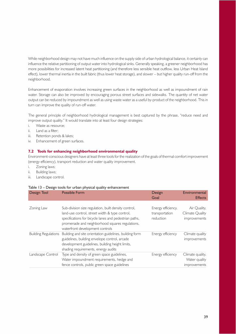
39
While neighborhood design may not have much influence on the supply side of urban hydrological balance, it certainly caninfluence the relative partitioning of output water into hydrological sinks. Generally speaking, a greener neighborhood hasmore possibilities for increased latent heat partitioning (and therefore less sensible heat outflow, less Urban Heat Islandeffect), lower thermal inertia in the built fabric (thus lower heat storage), and slower – but higher quality run-off from theneighborhood.
Enhancement of evaporation involves increasing green surfaces in the neighborhood as well as impoundment of rainwater. Storage can also be improved by encouraging porous street surfaces and sidewalks. The quantity of net wateroutput can be reduced by impoundment as well as using waste water as a useful by-product of the neighborhood. This inturn can improve the quality of run-off water.
The general principle of neighborhood hydrological management is best captured by the phrase, “reduce need andimprove output quality.” It would translate into at least four design strategies:i. Waste as resource;ii. Land as a filter;iii. Retention ponds & lakes;iv. Enhancement of green surfaces.
7.2 Tools for enhancing neighborhood environmental qualityEnvironment-conscious designers have at least three tools for the realization of the goals of thermal comfort improvement(energy efficiency), transport reduction and water quality improvement.i. Zoning laws;ii. Building laws;iii. Landscape control.
Table 13 – Design tools for urban physical quality enhancementDesign Tool Possible Form Design Environmental
Goal Effects
Zoning Law Sub-division size regulation, built density control, Energy efficiency, Air Quality,land-use control, street width & type control, transportation Climate Qualityspecifications for bicycle lanes and pedestrian paths, reduction improvementspromenade and neighborhood squares regulations,waterfront development controls
Building Regulations Building and site orientation guidelines, building form Energy efficiency Climate qualityguidelines, building envelope control, arcade improvementsdevelopment guidelines, building height limits,shading requirements, energy audits
Landscape Control Type and density of green space guidelines, Energy efficiency Climate quality,Water impoundment requirements, hedge and Water qualityfence controls, public green space guidelines improvements
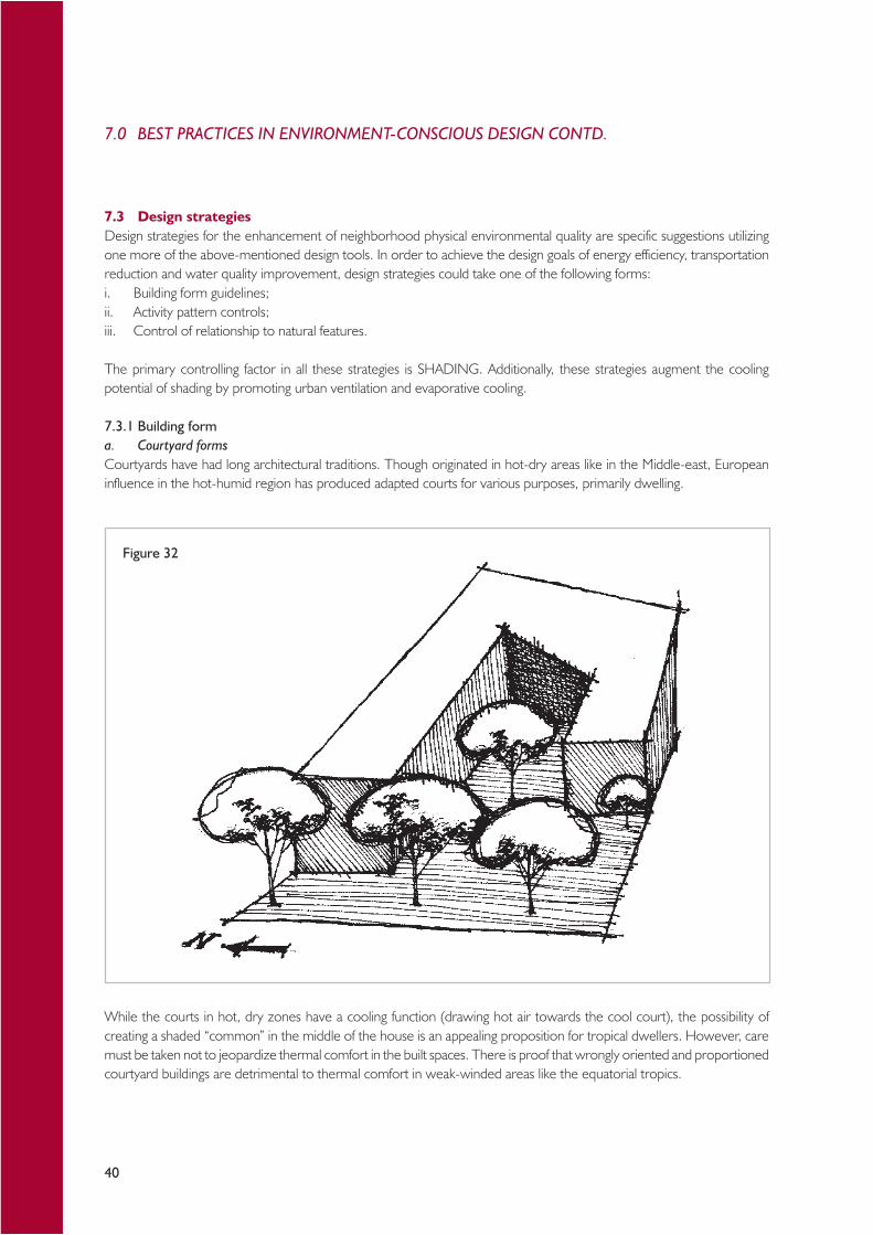
40
7.3 Design strategiesDesign strategies for the enhancement of neighborhood physical environmental quality are specific suggestions utilizingone more of the above-mentioned design tools. In order to achieve the design goals of energy efficiency, transportationreduction and water quality improvement, design strategies could take one of the following forms:i. Building form guidelines;ii. Activity pattern controls;iii. Control of relationship to natural features.
The primary controlling factor in all these strategies is SHADING. Additionally, these strategies augment the coolingpotential of shading by promoting urban ventilation and evaporative cooling.
7.3.1 Building forma. Courtyard formsCourtyards have had long architectural traditions. Though originated in hot-dry areas like in the Middle-east, Europeaninfluence in the hot-humid region has produced adapted courts for various purposes, primarily dwelling.
While the courts in hot, dry zones have a cooling function (drawing hot air towards the cool court), the possibility ofcreating a shaded “common” in the middle of the house is an appealing proposition for tropical dwellers. However, caremust be taken not to jeopardize thermal comfort in the built spaces. There is proof that wrongly oriented and proportionedcourtyard buildings are detrimental to thermal comfort in weak-winded areas like the equatorial tropics.
Figure 32
7.0 BEST PRACTICES IN ENVIRONMENT-CONSCIOUS DESIGN CONTD.
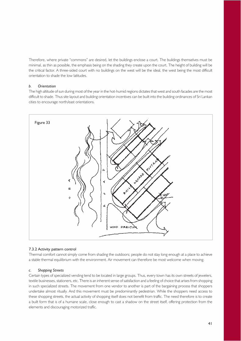
41
Therefore, where private “commons” are desired, let the buildings enclose a court. The buildings themselves must beminimal, as thin as possible, the emphasis being on the shading they create upon the court. The height of building will bethe critical factor. A three-sided court with no buildings on the west will be the ideal, the west being the most difficultorientation to shade the low latitudes.
b. OrientationThe high altitude of sun during most of the year in the hot-humid regions dictates that west and south facades are the mostdifficult to shade. Thus site layout and building orientation incentives can be built into the building ordinances of Sri Lankancities to encourage north/east orientations.
7.3.2 Activity pattern controlThermal comfort cannot simply come from shading the outdoors; people do not stay long enough at a place to achievea stable thermal equilibrium with the environment. Air movement can therefore be most welcome when moving.
c. Shopping StreetsCertain types of specialized vending tend to be located in large groups. Thus, every town has its own streets of jewelers,textile businesses, stationers, etc. There is an inherent sense of satisfaction and a feeling of choice that arises from shoppingin such specialized streets. The movement from one vendor to another is part of the bargaining process that shoppersundertake almost ritually. And this movement must be predominantly pedestrian. While the shoppers need access tothese shopping streets, the actual activity of shopping itself does not benefit from traffic. The need therefore is to createa built form that is of a humane scale, close enough to cast a shadow on the street itself, offering protection from theelements and discouraging motorized traffic.
Figure 33

42
Therefore, create canyon-like shopping streets in housing neighborhoods. The street itself should preferably be north/south running, with buildings on the west being slightly taller than those on the east. Line both facades of street-facingbuildings with arcades, so as to provide adequate protection from rain and sun. If north/south running streets are notavailable, create narrow shopping cul-de-sacs off traffic arteries, thus ensuring adequate protection from traffic, whilemaintaining accessibility.
d. Gathering PlacesWhile all climates need gathering spaces, the particular need in tropical climates is for negative ionization, a potentialbrought out by carefully designed outdoor environment. The presence of water has no rival in the tropics to match itsrevitalizing negative ionization effect. Thus, one could see thousands of city dwellers on Colombo's waterfront everyevening. The same is the case on Chennai’s Marina beach, the second largest in the world. Rio de Janeiro's waterfrontpromenades of course are legendary. People go there every day (except when it rains continuously) even though someof these environments are not thoughtfully developed.
The tropics are blessed with highly usable outdoors. The design issue therefore is one of thoughtful manipulation ofoutdoor design variables like awnings, canopies, landscaping, street furniture, etc., for gathering.
Figure 34
7.0 BEST PRACTICES IN ENVIRONMENT-CONSCIOUS DESIGN CONTD.

43
Therefore, create waterbodies at neighborhood scale and surround them with a built form edged by arcades. Locatepublic activities along the arcade, overflowing into the commons. If north/east facing promenades are desired, locate thebuildings in an “L” shape along the southern and western edges of water. If south/west facing arcades are desired, locatebuildings along the northern edge of water, in a staggered manner. The commons in the latter case needs to be wider.Trees need to be planted so as to provide intermittent shading to the commons. Dissuade all activities that do not directlybenefit from water’s edge from locating on the waterfronts.
e. Provisions for evening lifeEvenings are tropics’ winter. The places deserted in the heat of the day are slowly re-occupied by throngs of people as thesearing afternoon sun bids farewell and darkness envelopes the land. Thus, city centers in southern Indian small towns andbeach resorts from Sri Lanka to Brazil begin to come alive at dusk with evening bazaars and pedestrians.
Street corners are especially attractive to be incorporated into the evening life, particularly if they intersect northerly andeasterly orientation.
f. Pedestrian Paths and NodesThere are two kinds of traffic: transport which is motorized, capital-intensive and therefore scarce by definition, and transitwhich is self-powered and therefore labor-intensive. In the resource-starved hot-humid regions, it is clear that traffic mustbe biased towards transit. It is the most energy-saving and ecologically-sound thing to do in the region.
Figure 35
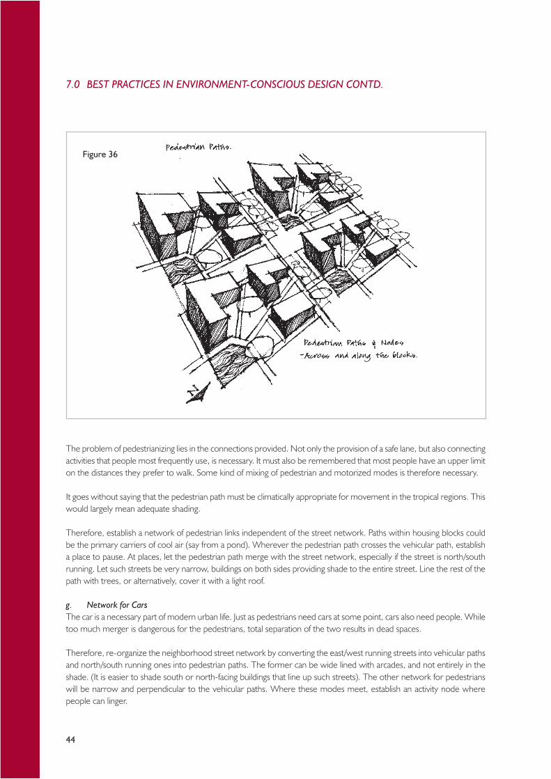
44
The problem of pedestrianizing lies in the connections provided. Not only the provision of a safe lane, but also connectingactivities that people most frequently use, is necessary. It must also be remembered that most people have an upper limiton the distances they prefer to walk. Some kind of mixing of pedestrian and motorized modes is therefore necessary.
It goes without saying that the pedestrian path must be climatically appropriate for movement in the tropical regions. Thiswould largely mean adequate shading.
Therefore, establish a network of pedestrian links independent of the street network. Paths within housing blocks couldbe the primary carriers of cool air (say from a pond). Wherever the pedestrian path crosses the vehicular path, establisha place to pause. At places, let the pedestrian path merge with the street network, especially if the street is north/southrunning. Let such streets be very narrow, buildings on both sides providing shade to the entire street. Line the rest of thepath with trees, or alternatively, cover it with a light roof.
g. Network for CarsThe car is a necessary part of modern urban life. Just as pedestrians need cars at some point, cars also need people. Whiletoo much merger is dangerous for the pedestrians, total separation of the two results in dead spaces.
Therefore, re-organize the neighborhood street network by converting the east/west running streets into vehicular pathsand north/south running ones into pedestrian paths. The former can be wide lined with arcades, and not entirely in theshade. (It is easier to shade south or north-facing buildings that line up such streets). The other network for pedestrianswill be narrow and perpendicular to the vehicular paths. Where these modes meet, establish an activity node wherepeople can linger.
Figure 36
7.0 BEST PRACTICES IN ENVIRONMENT-CONSCIOUS DESIGN CONTD.

45
7.3.3 Relationship to natural features – landscape controlsThe cooling potentials of natural elements like water and vegetation in a hot-humid place should be well utilized. Yet urbanenvironments also are harmful to the well-being of vegetation and waterbodies.
h. Relationship to WaterbodiesThe potential of water in cooling is substantial even in the humid regions. However, care must be taken not to overloadthe already heavy relative humidities of the tropics.
Contemporary thermal comfort equation shows that high humidities can be compensated by lower air and radianttemperatures. Although it is generally assumed that the primary cause of thermal discomfort in the tropics is humidity,studies have shown that at lower air temperatures humidity's effect on comfort is minimal.
The design strategy in incorporating water into neighborhood design in the humid regions is one of careful provision ofjust adequate water for evaporation. Furthermore, if waterbodies can be located to take advantage of the general airmovement patterns in the region, the air itself can be “conditioned,” thus increasing its potential for cooling.
Therefore, locate waterbodies in every neighborhood at the northeastern / southwestern corner of city blocks. Let somemajor traffic routes (pedestrian paths if within a housing block) connect these pools of water diagonally. At larger scales,rearrange street network to take advantage of air movement thus created by such diagonal paths (i.e. perpendicular to thediagonal paths). Plant trees around waterbodies to increase the cooling potential of air.
i. Contiguous Green AreasInstead of opening up large parts of the proposed development to greenery, contiguous greens can be provided that takeinto account the general wind patterns of a neighborhood and the general monsoon wind directions. Thus the coolingpotential of air can be enhanced, the ability of greens to reduce flash floods increased, and the spread of evapo-transpiratoryagents can be made more even. The size of greens, however, is a critical factor.
Another important factor is the type of greens provided. While most green areas in cities are park-like (single or groups oftrees amidst lawns), climate-enhancing potential of green areas can be increased by the provision of neighborhood-scale“mini-forests,” where wild growth of trees is encouraged. Make every effort to connect green areas in a diagonal manner(northeast-southwest). Combine such connected greens with the pedestrian network.
Figure 37
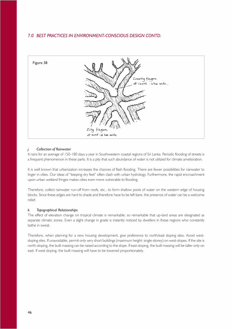
46
j. Collection of RainwaterIt rains for an average of 150-180 days a year in Southwestern coastal regions of Sri Lanka. Periodic flooding of streets isa frequent phenomenon in these parts. It is a pity that such abundance of water is not utilized for climate amelioration.
It is well known that urbanization increases the chances of flash flooding. There are fewer possibilities for rainwater tolinger in cities. Our ideas of “keeping dry feet” often clash with urban hydrology. Furthermore, the rapid encroachmentupon urban wetland fringes makes cities even more vulnerable to flooding.
Therefore, collect rainwater run-off from roofs, etc., to form shallow pools of water on the western edge of housingblocks. Since these edges are hard to shade and therefore have to be left bare, the presence of water can be a welcomerelief.
k. Topographical RelationshipsThe effect of elevation change on tropical climate is remarkable; so remarkable that up-land areas are designated asseparate climatic zones. Even a slight change in grade is instantly noticed by dwellers in these regions who constantlybathe in sweat.
Therefore, when planning for a new housing development, give preference to north/east sloping sites. Avoid west-sloping sites. If unavoidable, permit only very short buildings (maximum height: single-storey) on west-slopes. If the site isnorth-sloping, the built massing can be raised according to the slope. If east-sloping, the built massing will be taller only oneast. If west sloping, the built massing will have to be lowered proportionately.
Figure 38
7.0 BEST PRACTICES IN ENVIRONMENT-CONSCIOUS DESIGN CONTD.
47
7.4 Layout of individual housesIn the coastal belt of Sri Lanka, the following strategies may bring better thermal comfort and offer greater protectionagainst sea surges, storms and tsunamis:i. The buildings should be oriented in such a manner that the shorter side of the building faces the sea.ii. Wherever possible, sea facing walls should be braced by cross walls, so that the length of an unsupported wall does
not exceed 3m.iii. The aspect ratio of the building (Length to Width ratio) should not be greater than 3.iv. Ornamental features such as elaborate cornices, vertical or horizontal cantilever projections, fascia stones and the
like should be avoided.v. The openings in the building will encourage flood penetration. Hence large openings on the seaside should be
avoided.
When locating a group of buildings, a cluster arrangement should be chosen in preference to row type arrangement(Figure 39). However, clear paths should be identified for evacuation to high ground or to a nearby community building.
Another important factor to be considered is the proportions of a typical plot. The length and breadth of a typical plotshould be determined, giving importance to the following factors:i. Positioning of building line;ii. Rear space required by local authority;iii. Allowable distance between well and septic tank;iv. Provision for vertical and horizontal extension of house.
Boundary wall / fence: RecommendedLive fence (using plants that are best suited to the coast)Stone wall (not more than 3’high)
The means of evacuation can be elevated podiums, platforms, towers or roof terraces. Cycle tracks and walkways arerecommended to be provided in the settlements, if the density of housing exceeds 20 units.
7.5 Housing types suitable for coastal re-buildingAs far as possible, a variety of house forms and a multitude of detailing should be adopted in a settlement to avoidmonotony and establish identity of the beneficiary families.i. Stand alone house forms
(a) Single storey(b) Storied individual housing(c) Storied attached houses/town houses (row-houses to be avoided in vulnerable areas)
ii. Walk-up apartments (physical infrastructure is a decisive factor)
Positive aspects of stand-alone houses (single storey, storied individual or storied attached):i. Housing unit stands on an individual plot of land with front and rear garden.ii. Possible user participation in design and construction is very high.iii. In a “Core shell” concept, the core of the house is provided by the designer or developer with the essential spaces
such as living room, kitchen and toilet. Rest of the building has to be completed by the beneficiary according to hismeans and to meet his aspirations. Incremental (vertical and horizontal) expansion is also possible.
iv. House stands on individual plot of land with individual services (sewage and waste water disposal and electricity /water supply)
v. Maintenance done by the occupants themselves without inconvenience to neighbor or burden to the local authorities.
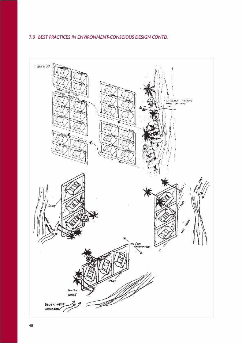
48
Figure 39
7.0 BEST PRACTICES IN ENVIRONMENT-CONSCIOUS DESIGN CONTD.
49
The walk-up apartment is an assembly of housing units, arranged in different floors, one over the other in vertical form (upto ground and three upper floors and ground and four upper floors, if ground floor is used for parking). Elements beingshared with one another are structure, services, staircase, walkways and common land for recreational and other commonactivities.
The following suggestions will reduce unfavorable conditions of flats for community living.i. Ensure grouping of vertical service lines into a service core, which is accessible for servicing from a common lobby
but not through individual units.ii. Avoid horizontal service lines from crossing the apartments, but provide service connections to each unit directly
from the vertical service core.iii. Make provisions to carry-out maintenance (repairs/color washing) work on exterior walls.iv. Maintenance of the common elements/areas should be made the responsibility of not only the occupants, but also
the local authority.

50
8.1 Accessibility for allPost-disaster re-construction needs to pay special attention to the needs of the physically challenged individuals and theelderly. While accessibility for all is a desirable goal, its importance gains added significance in times of great upheaval, as isthe case following natural and man-made disasters.
8.1.1 General principleThe main goal of the exercise is to ensure that buildings and facilities be accessible for the wheel-chair bound. Undernormal circumstances, this would mean that the most basic facilities are located on grade or, if impossible, accessible by ashallow ramp.
Figure 40 shows the basic considerations recommended to be adopted in designing buildings for universal access.
8.1.2 ToiletsA particularly challenging need is to provide accessible toilets. Although it is desirable that several other crucial facilities beprovided with wheelchair access, it is recommended that at least one toilet in each communal building be made wheelchair-accessible.
8.0 DESIRABLE TECHNICAL FEATURES IN POST-DISASTERHOUSING
Figure 40
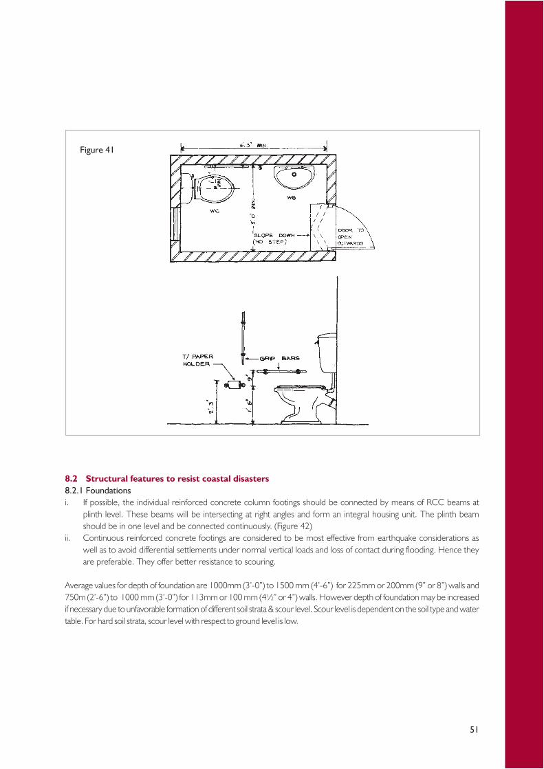
51
8.2 Structural features to resist coastal disasters8.2.1 Foundationsi. If possible, the individual reinforced concrete column footings should be connected by means of RCC beams at
plinth level. These beams will be intersecting at right angles and form an integral housing unit. The plinth beamshould be in one level and be connected continuously. (Figure 42)
ii. Continuous reinforced concrete footings are considered to be most effective from earthquake considerations aswell as to avoid differential settlements under normal vertical loads and loss of contact during flooding. Hence theyare preferable. They offer better resistance to scouring.
Average values for depth of foundation are 1000mm (3’-0”) to 1500 mm (4’-6”) for 225mm or 200mm (9” or 8”) walls and750m (2’-6”) to 1000 mm (3’-0”) for 113mm or 100 mm (4½” or 4”) walls. However depth of foundation may be increasedif necessary due to unfavorable formation of different soil strata & scour level. Scour level is dependent on the soil type and watertable. For hard soil strata, scour level with respect to ground level is low.
Figure 41
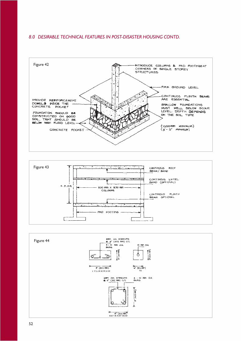
52
Figure 42
Figure 43
Figure 44
8.0 DESIRABLE TECHNICAL FEATURES IN POST-DISASTER HOUSING CONTD.

53
8.2.2 Wallsi. In addition to the lintel beam and corner columns, a continuous, plinth beam and roof band can be considered (see
Figure 43), on both external and internal walls. This will make the building act as an integral unit under lateral forces.ii. Reinforcing bars can be introduced at wall intersections and jambs of openings. These should be surrounded by concrete of
size 100mm (Figure 44). The anchorage should extend from the ground beam to the roof beam. All bars should have an‘L’ bend of 300 mm in length.
8.3.3 Openingsi. It is desirable to provide reinforced bands or ties around the openings. (Figure 44)ii. The frames should be well anchored to the walls.
8.3.4 Roof structuresi. A flat reinforced concrete roof is preferable to the lightweight roofs discussed above. A minimum thickness of
100mm and minimum grade of 20 should be used. A gentle slope provided for the flat roof (e.g. 1 in 100) will enable quickdrainage of rainwater. Vertical reinforcement bars from the walls should be tied and anchored in the roof slab.
ii. If cantilevers cannot be avoided, they should be well anchored to protect them from earthquake damage. (Figure45)
Figure 45

54
The Institute for Construction Training and Development (ICTAD), National Engineering Research and Development(NERD) Center, National Building Research Organization (NBRO) and Sri Lankan private-sector manufacturers of buildingmaterials have published best practice guides for building materials and their usage. Appendix 2 refers to some of the mostpertinent materials. Readers are advised to consult these publications for further information.
9.1 Alternate materials and methodsA. WallsAn alternate material for coastal re-building is the stabilized soil blocks. The positive features of this material are:i. Decentralized production with the help of a simple manual compaction press,ii. Scales of production can be adjusted depending on the requirement,iii. Production on site, thus avoiding transportation,iv. Wet compressive strength in the range of 35-45kg/cm3,v. Local employment generation potential (six direct jobs per block-making machine),vi. Large block size (23cm x 19cm x 10cm) reduces mortar consumption, speeds up wall construction and increases
wall strength,vii. Neat and dense blocks are erosion resistant and hence do not require external plastering, thus saving on cost of
construction,
If burnt brick is the choice wall material, efficient construction is possible with rat trap bond which saves up to 25% of thewalling cost and improves thermal comfort without compromising the structural stability.
To save cost of reinforced cement concrete lintels, it is possible to use arched openings for doors and windows. Archescould be built with stabilized soil blocks or burnt bricks and are aesthetically pleasing.
B. Doors and window sashes and frames:An alternate to wood/metal door and window frames is the Reinforced Cement Concrete (RCC) frames. These RCCframes can be locally manufactured and are up to 25% cheaper than the timber or steel frames. Furthermore, theyrequire less maintenance and do not require painting.
Alternate sash materials include:i. Mild steel,ii. Ferro cement,iii. Cement bonded particle board.
C. Roofing:Roof frame and joists could be made of pre-cast RCC or ferro cement joists. They are cheaper, maintenance free andresistant to termites.
Although micro-concrete roofing tiles are a viable roof cover option in Sri Lanka, poor thermal properties and the needfor mechanized production may not make them suitable for housing in the warm-humid zone.
9.0 BEST PRACTICES IN MATERIAL USE

55
Coastal Zone Management Plan (CZMP), (2004). Colombo: Coast Conservation Dept.
Colombo Development Plan, (1999). Battaramulla, Sri Lanka: Urban Development Authority.
Colombo Metropolitan Regional Structure Plan (CMRSP), (1998). Volumes I - XII. Colombo, Sri Lanka: Urban DevelopmentAuthority.
Emmanuel, R., (2005). An Urban Approach to Climate Sensitive Design: Strategies for the Tropics, London: E & FN SponPress, 178 pp.
Institute for Construction Training And Development (ICTAD), (1997). ICTAD Specification for Building Works, vol. 1,Colombo.
Promotion of Accessibility to Built Environment for Persons with Disabilities, (1998). Addendum to Report: Book Four –Planning and Design Guide, Colombo: Ministry of Social Services.
Revised Coastal Zone Management Plan (CZMP), (1997). Colombo: Coast Conservation Dept., 123 pp.
Society of Structural Engineers, Sri Lanka (SSESL), (2005). Guidelines for Buildings at Risk from Natural Disasters, Colombo:SSESL, 22 pp.
Bibliography
56
Resource Persons
01. Mr. S. R. Kanaganayagam - Addl. Secretary( Technical )FIE(SL),MICE(Lond.),BSc Eng.(Hons) Ministry of Housing & Construction
02. Mr. Nihal Somaweera - Addl. Secretary (Technical )MIE(SL), MITP(SL), MSc(T &CP), BSc(Civil Eng.) Ministry of Urban Development &Water Supply
03. Mr. Ananda Gamage - Supdt. Engineer, CMCMIE(SL), MITP(SL),M.phil , P.G.Dip(En.Ey&Mgt), MSc (T&CP),BSc(Eng.)
04. Mr. K A Jayarathna - President, SEVANATHAMSLITP, FIRE, MSc, BSc
05. Prof. M.T.R.Jayasinghe - Dept. of Civil EngineeringPhd (Cambridge),BSc Eng.(Hons) University of Moratuwa
06. Dr. Locana Gunarathne - Consultant , Ministry ofFIA(SL),RIBA,FITP(SL),MCP(Harvard),AIA.DIP(Lond.) Urban Development & Water Supply
07. Mr. A U Sarathchandra - Senior Engineer, CCDMIE(SL), PG Dip. Port&Coastal Eng.(Trondheim), BSc.(Nat.Sc.), MIE(SL)
08 Mr. P P Gnanapala - Deputy General Manager (R&D) SLLRDCMIE(SL),MICE(Lond.),DHE(Delft),M.Eng,BSc.Eng.
09. Ms. W D S Indrasiri - Director (Enforcement) UDA MITF(SL),PG.Dip(GIS)(Urban)-Netherlands, MSc(T&CP),B.Dev.(SP)
10 Ms. Nadeeka Perera - Chief EngineerMIE(SL) ,BSc.Eng.,PG.Dip(Env Eng.), P.G.Dip (Struct) (Planning & Design)NWS&DB
11 Mr. Probash Budden - Shelter Advisor & Dty. Regional DirectorM.A.(Econ.&Political Dev.)-USA CRS – South East Asia
12 Mr. G A P Ganepola - Director(Construction)FIA(SL),RIBA,MSc.(Arch),BSc(BE) Ministry of Housing & Construction
13 Mr. Nihal Perera - Deputy General Manager ( Structural Design)MICE(Lond),MSc(Struct),PG Dip(Hyd&WRE), CECB, BSc Eng.(Hons)
14 Mr. D.F. Weudagedara - Director, Dept. of BuildingsMIE(SL).(UK),MSc(Struct.), MSc Eng.Hons.
15 Mr. Eric Ediriwickrama - Deputy General Manager (HousingMIE(SL), PG.Dip.(Netherlands),BSc.(Eng.) Construction & Maintenance) NHDA
16 Mr S D Dhanapala - Asst. General Manager (Construction) NHDAMIE(SL) ,MSc Eng.(Moscow)
17. Mr. Harsha De Silva - Director (Planning &Monitoring) THRUB.Sc (BE,), P.G.DIP.(Netherlands)
18. Mr Sagara Palansooriya - Deputy General Manager ( Media )NHDAB.A
19. Mrs. Mekhala Jayawardena - Senior Architect, NHDAAIA (SL), MSc(Arch),BSc.(BE)
20. Mrs. Mihiri Vipulaguna - Architect, NHDABSc(BE)
21. Mr. B.C. Fernando - AGM ( Electrical) NHDAMIE(SL), B.Sc (Eng)
22. Mrs. Dhammika Wijeratne - Program Officer, GTZAIA (SL),RIBA, MSc(Arch),BSc.(BE)
Helpers01. Ms. Renuka Ramanayaka - Secretarial Assistance02. Ms. Iranganie Bendarage - Secretarial Assistance03. Mr. Sanjeewa Fernando - Liaison with Resource Persons04. Mr. W H Rupasinghe - Miscellaneous

57
APPENDIX 1 – Setback requirements for developmentactivities in the coastal zone(Source: CZMP, 1997, Table 6.2, pp. 86-90)
Segm
ent N
o.Ar
eaSo
urce
Map
Geog
raph
ical C
oord
inate
sLe
vel o
fSe
tbac
k D
istan
ce in
(m)
Tota
l(o
ne in
ch)
Latit
ude
(N)
Long
itude
(E)
Vulne
rabil
ityRe
serv
atio
nRe
strict
edSe
tbac
kAr
eaAr
eaAr
ea (m
)
1Ka
la O
ya R
iver
mou
th to
Kan
daku
liya
Kalp
itiya
8°17
'56"
79°5
5'00
"M
ediu
m(-
)15
3045
8°12
'36"
79°4
1'55
"2
Kand
akul
iya
to U
ddap
pu S
outh
Putta
lam8°
12'3
6"79
°41'
55"
Med
ium
(+)
2030
50Ba
ttulu
Oya
7°44
'30"
79°4
7'16
"3
Uda
ppu
Sout
h to
Sin
na K
aruk
kapo
neBa
ttulu
Oya
7°44
'30"
79°4
7'16
"M
ediu
m(-
)15
3045
Chi
law7°
37'3
0"79
°47'
50"
4Si
nna
Karu
kkap
one
to T
oduw
awa
Nor
thC
hilaw
7°37
'30"
79°4
7'50
"H
igh(
-)20
3555
7°29
'35"
79°4
7'40
"5
Todu
waw
a N
orth
to M
uduk
atuw
aC
hilaw
7°29
'35"
79°4
7'40
"Lo
w(+
)15
2540
Koch
chika
de7°
24'0
5"79
°49'
05"
6M
uduk
atuw
a to
Por
utot
aKo
chch
ikade
7°24
'05"
79°4
9'05
"M
ediu
m(+
)20
3050
7°15
'36"
79°5
0'22
"7
Poru
tota
to K
amac
hcho
deKo
chch
ikade
7°15
'36"
79°5
0'22
"Lo
w(+
)15
2540
Neg
ombo
7°12
'52"
79°4
9'55
"8
Kam
achc
hode
to D
uwa
Neg
ombo
7°12
'52"
79°4
9'55
"H
igh(
+)
2535
607°
12'2
8"79
°49'
07"
9D
uwa
to U
swat
ekei
yaw
aN
egom
bo7°
12'2
8"79
°49'
07"
Med
ium
(-)
1530
457°
02'4
0"79
°51'
15"
10U
swat
ekei
yaw
a to
Mou
nt L
avin
ia H
otel
Neg
ombo
7°02
'40"
79°5
1'15
"H
igh(
-)20
3555
Col
ombo
6°50
'06"
79°5
1'35
"11
Mou
nt L
avin
ia H
otel
to P
inw
atta
Rail
way
Sta
tion
Col
ombo
6°50
'06"
79°5
1'35
"M
ediu
m(-
)15
3045
Kalu
tara
6°41
'17"
79°5
4'35
"12
Pinw
atta
Rail
way
Sta
tion
to T
ange
rine
Hot
elKa
luta
ra6°
41'1
7"79
°54'
35"
Low
(-)
1025
356°
36'2
3"79
°56'
46"
13Ta
nger
ine
Hot
el to
Sin
bad
Hot
elKa
luta
ra6°
36'2
3"79
°56'
46"
Hig
h(+
)25
3560
6°33
'54"
79°5
7'32
"14
Sinb
ad H
otel
to P
ayag
ala S
outh
Kalu
tara
6°33
'54"
79°5
7'32
"M
ediu
m(+
)20
3050
Alut
hgam
a6°
31'1
3"79
°58'
37"
15Pa
yaga
la So
uth
to M
aggo
na B
ridge
Alut
hgam
a6°
31'1
3"79
°58'
37"
Low
(+)
1525
406°
29'5
4"79
°58'
42"

58
Segm
ent N
o.Ar
eaSo
urce
Map
Geog
raph
ical C
oord
inate
sLe
vel o
fSe
tbac
k D
istan
ce in
(m)
Tota
l(o
ne in
ch)
Latit
ude
(N)
Long
itude
(E)
Vulne
rabil
ityRe
serv
atio
nRe
strict
edSe
tbac
kAr
eaAr
eaAr
ea (m
)
16M
aggo
na B
ridge
to C
onfifi
Hot
elAl
uthg
ama
6°29
'54"
79°5
8'42
"H
igh(
+)
2535
606°
27'1
7"79
°58'
31"
17C
onfifi
Hot
el to
Yak
gaha
gala
to In
duru
wa
Alut
hgam
a6°
27'1
7"79
°58'
31"
Low
(+)
1525
406°
23'5
5"80
°00'
16"
18Ya
kgah
agala
to K
osgo
da R
iver
Mou
thAl
uthg
ama
6°23
'55"
80°0
0'16
"M
ediu
m(+
)20
3050
6°20
'25"
80°0
1'24
"19
Kosg
oda
Rive
r Mou
th to
Wel
lawat
te B
alapi
tiya
Alut
hgam
a6°
20'2
5"80
°01'
24"
Low
(-)
1025
35Ba
lapiti
ya6°
16'0
0"80
°01'
53"
20W
ellaw
atte
Bala
pitiy
a to
Cor
al G
arde
ns H
otel
,Ba
lapiti
ya6°
16'0
0"80
°01'
53"
Med
ium
(-)
1530
45H
ikkad
uwa
Amba
lango
da6°
08'5
5"80
°03'
52"
21C
oral
Gar
dens
Hot
el, H
ikkad
uwa
toAm
balan
goda
6°08
'55"
80°0
3'52
"Lo
w(-
)10
2535
Dev
apat
iraja
Mah
a Vi
dyala
ya, R
atga
ma
Gall
e6°
04'5
7"80
°08'
46"
22D
evap
atira
ja M
aha
Vidy
alaya
to G
into
ta R
iver
Gall
e6°
04'5
7"80
°08'
46"
Med
ium
(+)
2030
506°
03'2
5"80
°10'
32"
23G
into
ta R
iver
to M
aha
Mod
ara
Gall
e6°
03'2
5"80
°10'
32"
Med
ium
(-)
1530
456°
02'2
5"80
°11'
30"
24M
aha
Mod
ara
to C
emen
t Fac
tory
, Gall
eG
alle
6°02
'25"
80°1
1'30
"H
igh(
-)20
3555
6°01
'40"
80°1
4'25
"25
Cem
ent F
acto
ry, G
alle
to W
elle
Dew
alaya
Gall
e6°
01'4
0"80
°14'
25"
Low
(+)
1525
406°
00'2
0"80
°14'
25"
26W
elle
Dew
alaya
to K
ogga
la H
ousin
gG
alle
6°00
'20"
80°1
4'25
"Lo
w(-
)10
2535
Sche
me
(129
km)
6°00
'25"
80°1
5'03
"27
Kogg
ala H
ousin
g Sc
hem
e (1
29km
) to
Gall
e6°
00'2
5"80
°15'
03"
Med
ium
(-)
1530
45Ka
talu
wa
Brid
ge5°
58'5
5"80
°20'
00"
28Ka
talu
wa
Brid
ge to
Mid
igam
aG
alle
5°58
'55"
80°2
0'00
"H
igh(
-)20
3555
Mat
ara
5°57
'30"
80°2
3'55
"29
Mid
igam
a to
Wall
iwala
Eas
t (14
0km
)M
atar
a5°
57'3
0"80
°23'
55"
Low
(-)
1025
355°
57'4
5"80
°25'
08"
30W
alliw
ala E
ast (
140k
m) t
o Pa
lana
Mat
ara
5°57
'45"
80°2
5'08
"H
igh(
+)
2535
605°
58'1
7"80
°26'
06"
31Pa
lana
to M
adih
a Ea
stM
atar
a5°
58'1
7"80
°26'
06"
Low
(+)
1025
355°
56'1
7"80
°30'
05"
APPENDIX 1 CONTD.
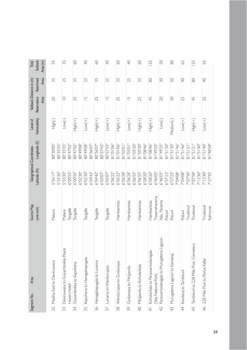
59
Segm
ent N
o.Ar
eaSo
urce
Map
Geog
raph
ical C
oord
inate
sLe
vel o
fSe
tbac
k D
istan
ce in
(m)
Tota
l(o
ne in
ch)
Latit
ude
(N)
Long
itude
(E)
Vulne
rabil
ityRe
serv
atio
nRe
strict
edSe
tbac
kAr
eaAr
eaAr
ea (m
)
32M
adih
a Ea
st to
Dev
inuw
ara
Mat
ara
5°56
'17"
80°3
0'05
"H
igh(
-)20
3555
5°55
'30"
80°3
5'35
"33
Dev
inuw
ara
to G
oyam
bokk
a Pe
ace
Mat
ara
5°55
'30"
80°3
5'35
"Lo
w(-
)10
2535
Hav
en H
otel
Tang
alle
6°00
'55"
80°4
7'02
"34
Goy
ambo
kka
to K
apuh
ena
Tang
alle
6°00
'55"
80°4
7'02
"H
igh(+
)25
3560
6°02
'30"
80°4
9'08
"35
Kapu
hena
to H
enag
ahap
ugala
Tang
alle
6°02
'30"
80°4
9'08
"Lo
w(+
)15
2540
6°04
'42"
80°5
6'07
"36
Hen
agah
apug
ala to
Lun
ama
Tang
alle
6°04
'42"
80°5
6'07
"H
igh(
+)
2535
606°
05'0
7"80
°57'
43"
37Lu
nam
a to
Wan
duru
ppa
Tang
alle
6°05
'07"
80°5
7'43
"Lo
w(+
)15
2540
6°06
'22"
81°0
1'06
"38
Wan
duru
ppa
to G
odaw
aya
Ham
bant
ota
6°06
'22"
81°0
1'06
"H
igh(+
)25
3560
6°06
'28"
81°0
3'01
"39
God
away
a to
Miri
jjaw
ilaH
amba
ntot
a6°
06'2
8"81
°03'
01"
Low
(+)
1525
406°
06'5
5"81
°05'
30"
40M
irijja
wila
to K
ohol
anka
laH
amba
ntot
a6°
06'5
5"81
°05'
30"
Hig
h(+
)25
3560
6°08
'20"
81°0
8'46
"41
Koho
lanka
la to
Par
awam
odar
agala
Ham
bant
ota
6°08
'20"
81°0
8'46
"H
igh(+
)45
8012
5(Y
ala N
atio
nal P
ark)
Tiss
amah
aram
a6°
46'0
5"81
°49'
25"
42Pa
raw
amod
arag
ala to
Mur
ugat
ena
Lago
onYa
la, P
anam
a6°
46'0
5"81
°49'
25"
Low
(-)
2030
50Po
tuvi
l6°
57'2
3"81
°51'
30"
43M
urug
aten
a La
goon
to K
anda
raj
Potu
vil
6°57
'23"
81°5
1'30
"M
ediu
m(-
)30
5080
7°04
'08"
81°5
1'46
"44
Kand
araj
to T
ambi
luvi
lPo
tuvi
l7°
04'0
8"81
°51'
46"
Low
(+)
2540
65Ti
rukk
ovil
7°07
'58"
81°5
1'21
"45
Tam
bilu
vil t
o 22
8 M
ile P
ost,
Cem
eter
yTi
rukk
ovil
7°07
'58"
81°5
1'21
"H
igh(
+)
4580
125
7°12
'30"
81°5
1'40
"46
228
Mile
Pos
t to
Periy
a Ka
llar
Tiru
kkov
il7°
12'3
0"81
°51'
40"
Low
(+)
2540
65Ka
lmun
ai7°
27'4
5"81
°48'
58"
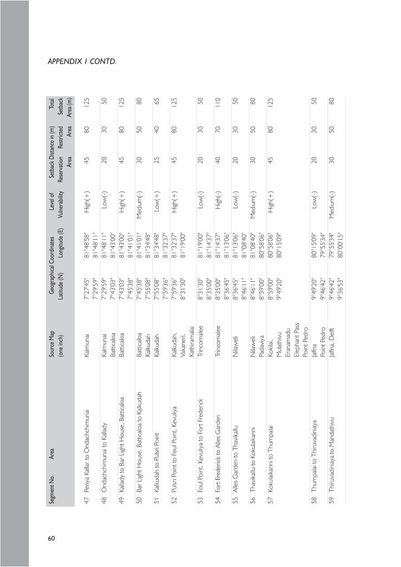
60
Segm
ent N
o.Ar
eaSo
urce
Map
Geog
raph
ical C
oord
inate
sLe
vel o
fSe
tbac
k D
istan
ce in
(m)
Tota
l(o
ne in
ch)
Latit
ude
(N)
Long
itude
(E)
Vulne
rabil
ityRe
serv
atio
nRe
strict
edSe
tbac
kAr
eaAr
eaAr
ea (m
)
47Pe
riya
Kalla
r to
Ond
achc
him
unai
Kalm
unai
7°27
'45"
81°4
8'58
"H
igh(
+)
4580
125
7°29
'59"
81°4
8'11
"48
Ond
achc
him
unai
to K
allad
yKa
lmun
ai7°
29'5
9"81
°48'
11"
Low
(-)
2030
50Ba
ttica
loa
7°43
'03"
81°4
3'00
"49
Kalla
dy to
Bar
Lig
ht H
ouse
, Bat
ticalo
aBa
ttica
loa
7°43
'03"
81°4
3'00
"H
igh(
+)
4580
125
7°45
'38"
81°4
1'01
"50
Bar L
ight
Hou
se, B
attic
aloa
to K
alkud
ahBa
ttica
loa
7°45
'38"
81°4
1'01
"M
ediu
m(-
)30
5080
Kalku
dah
7°55
'08"
81°3
4'48
"51
Kalku
dah
to P
ulsr
i Poi
ntKa
lkuda
h7°
55'0
8"81
°34'
48"
Low
(+)
2540
657°
59'3
6"81
°32'
37"
52Pu
lsri P
oint
to F
oul P
oint
, Kev
uliy
aKa
lkuda
h,7°
59'3
6"81
°32'
37"
Hig
h(+
)45
8012
5Va
kane
ri,8°
31'3
0"81
°19'
00"
Kath
iram
alai
53Fo
ul P
oint
, Kev
uliy
a to
For
t Fre
deric
kTr
inco
male
e8°
31'3
0"81
°19'
00"
Low
(-)
2030
508°
35'0
0"81
°14'
37"
54Fo
rt Fr
eder
ick to
Alle
s G
arde
nTr
inco
male
e8°
35'0
0"81
°14'
37"
Hig
h(-)
4070
110
8°36
'45"
81°1
3'06
"55
Alle
s G
arde
n to
Tha
vika
lluN
ilaw
eli
8°36
'45"
81°1
3'06
"Lo
w(-
)20
3050
8°46
'11"
81°0
8'40
"56
Thav
ikallu
to K
okul
aikan
niN
ilaw
eli
8°46
'11"
81°0
8'40
"M
ediu
m(-
)30
5080
Pada
viya
8°59
'00"
80°5
8'06
"57
Koku
laika
nni t
o Th
umpa
laiKo
kilai,
8°59
'00"
80°5
8'06
"H
igh(
+)
4580
125
Mul
athi
vu9°
49'2
0"80
°15'
09"
Eran
amad
uEl
epha
nt P
ass
Poin
t Ped
ro58
Thum
palai
to T
hiru
vadi
niay
aJa
ffna
9°49
'20"
80°1
5'09
"Lo
w(-
)20
3050
Poin
t Ped
ro9°
46'4
2"79
°55'
34"
59Th
iruva
dini
aya
to M
anda
thiv
uJa
ffna,
Del
ft9°
46'4
2"79
°55'
34"
Med
ium
(-)
3050
809°
36'5
3"80
°00'
15"
APPENDIX 1 CONTD.
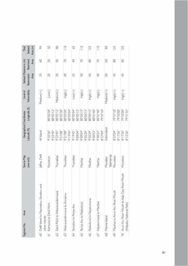
61
Segm
ent N
o.Ar
eaSo
urce
Map
Geog
raph
ical C
oord
inate
sLe
vel o
fSe
tbac
k D
istan
ce in
(m)
Tota
l(o
ne in
ch)
Latit
ude
(N)
Long
itude
(E)
Vulne
rabil
ityRe
serv
atio
nRe
strict
edSe
tbac
kAr
eaAr
eaAr
ea (m
)
60D
elft
Islan
d to
Nay
inat
ivu,
Kar
aitiv
u an
dJa
ffna,
Del
ftAl
l Isla
ndM
ediu
m(+
)35
6095
othe
r Isl
ands
61Ka
lmun
ai to
Dev
il Po
int
Poon
eryn
9°35
'56"
80°0
2'58
"Lo
w(-
)20
3050
9°23
'45"
80°0
3'12
"62
Dev
il Po
int t
o W
eera
vand
inm
unai
Thun
akka
i9°
23'4
5"80
°03'
12"
Med
ium
(-)
3050
809°
21'0
8"80
°03'
30"
63W
eera
vand
inm
unai
to S
inna
tivu
Thun
akka
i9°
21'0
8"80
°03'
30"
Hig
h(-)
4070
110
9°19
'45"
80°0
5'04
"64
Sinn
ativ
u to
Per
iya
Aru
Thun
akka
i9°
19'4
5"80
°05'
04"
Low
(+)
2540
659°
09'0
4"80
°05'
15"
65Pe
riya
Aru
to P
adav
itura
iM
anth
ai9°
09'0
4"80
°05'
15"
Hig
h(-)
4070
110
9°05
'29"
80°0
4'15
"66
Pada
vitu
rai t
o N
ayat
umun
aiM
anth
ai9°
05'2
9"80
°04'
15"
Hig
h(+
)45
8012
59°
00'5
3"80
°01'
40"
67N
ayat
umun
ai to
Man
thai
Man
thai
9°00
'53"
80°0
1'40
"H
igh(
-)40
7011
08°
57'0
4"79
°57'
10"
68M
anna
r Isla
ndM
uruk
kan
Entir
e Isl
and
Med
ium
(+)
3050
80Ta
laim
anna
r69
Man
thai
to A
ruvi
Aru
Riv
er M
outh
Mur
ukka
n8°
57'0
4"79
°57'
10"
Hig
h(+
)45
8012
58°
17'5
6"79
°55'
00"
70Ar
uvi A
ru R
iver
Mou
th to
Kala
Oya
Riv
er M
outh
Mur
ukka
n8°
17'5
6"79
°55'
00"
High
(+)
4580
125
(Wilp
attu
Nat
iona
l Par
k)8°
12'3
6"79
°41'
55"
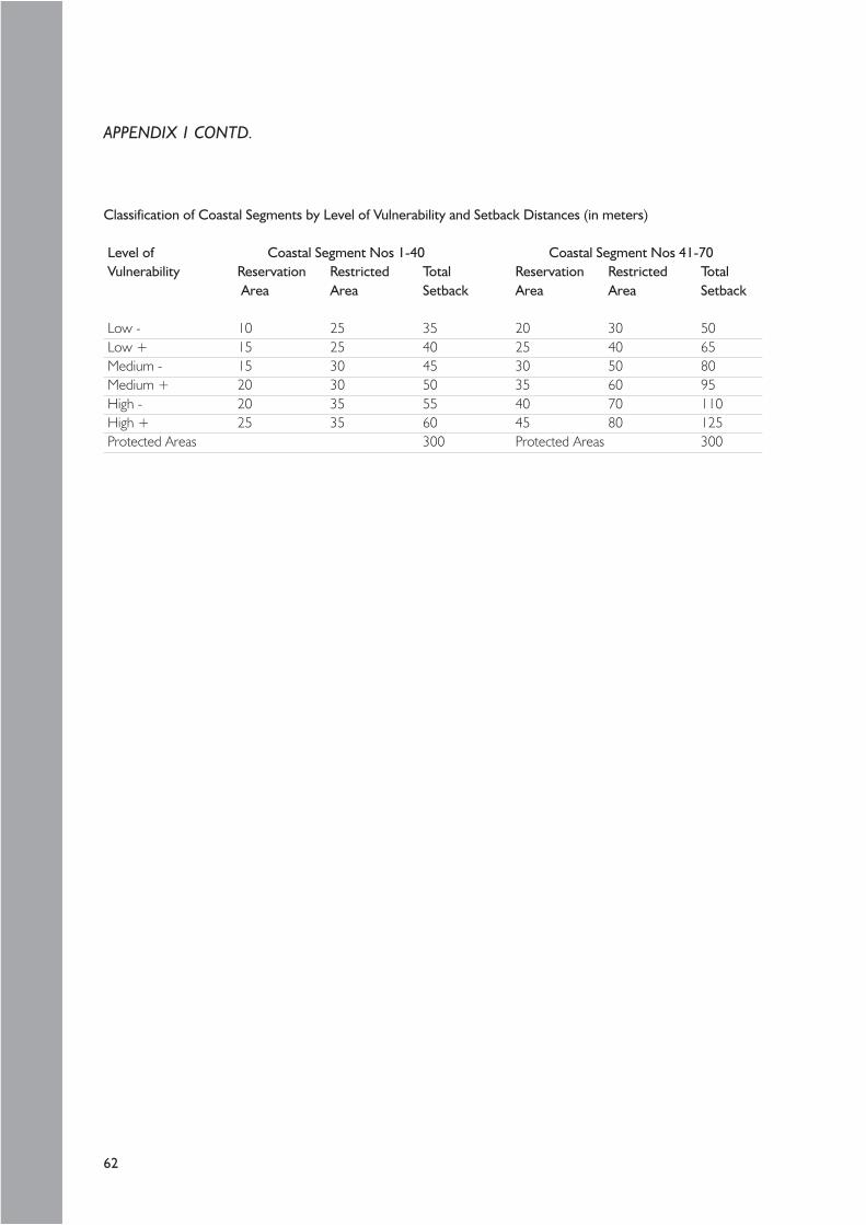
62
Classification of Coastal Segments by Level of Vulnerability and Setback Distances (in meters)
Level of Coastal Segment Nos 1-40 Coastal Segment Nos 41-70Vulnerability Reservation Restricted Total Reservation Restricted Total
Area Area Setback Area Area Setback
Low - 10 25 35 20 30 50Low + 15 25 40 25 40 65Medium - 15 30 45 30 50 80Medium + 20 30 50 35 60 95High - 20 35 55 40 70 110High + 25 35 60 45 80 125Protected Areas 300 Protected Areas 300
APPENDIX 1 CONTD.

63
APPENDIX 2 – Best practice in the use of conventionalbuilding materials
Part
of t
he b
uild
ing
Mat
erial
sM
etho
d of
App
licat
ion
Rele
vant
Spe
cifica
tion
Reco
mm
ende
d U
ses /
Lim
itatio
ns
1Fo
unda
tion
Rubb
leRa
ndom
rubb
le m
ason
ryIC
TAD
Spe
cifica
tions
for
Use
in sh
allow
foun
datio
ns in
firm
grou
ndBu
ilding
Wor
ks, v
ol. 1
, (P
refe
rabl
e fo
r sing
le sto
rey
build
ings,
for
Clau
se 7
.2m
ulti s
tore
y bu
ilding
s obt
ain p
rofe
ssio
nal a
dvise
)Br
icks
Brick
mas
onry
- Do
- Clau
se 6
.2U
se in
shall
ow fo
unda
tions
in fir
m gr
ound
(Pre
fera
ble
for s
ingle
store
y bu
ilding
s, fo
r mult
isto
rey
build
ings o
btain
pro
fess
iona
l adv
ise)
Cem
ent B
lock
sBl
ock m
ason
ry- D
o - C
lause
6.3
Use
in sh
allow
foun
datio
ns in
firm
grou
nd(P
refe
rabl
e fo
r sing
le sto
rey
build
ings)
Con
cret
eRC
C C
olum
n fo
oting
- Do
- Clau
se 5
.0U
se fo
r mult
i sto
rey
build
ings i
n fir
m g
roun
dRC
C S
trip
Foot
ing fo
rm
ason
ry fo
unda
tion
- Do
- Clau
se 5
.0U
se fo
r loa
d be
aring
wall
sRC
C p
linth
bea
m fo
rM
ason
ry fo
unda
tion
- Do
- Clau
se 5
.0U
se fo
r med
ium ri
se b
uildi
ngs i
n a w
eak s
oil
RCC
raft
foun
datio
n- D
o - C
lause
5.4
.4.2
- Do
-RC
C p
ile fo
unda
tion
- Do
- Clau
se 5
.0U
se fo
r mult
i sto
rey
build
ings i
n a w
eak
soil c
ondi
tion
2W
alls
Brick
Brick
mas
onry
wall
s- D
o - C
lause
6.2
4 1/
2" th
ick, o
nly fo
r non
load
bea
ring
wall
s9"
thick
wall
s can
be
used
as l
oad
bear
ingC
emen
t Hol
low
Bloc
k mas
onry
wor
ks- D
o - C
lause
6.3
4" th
ick, o
nly fo
r non
load
bea
ring
wall
sbl
ocks
6" th
ick &
8" t
hick
wall
s can
be
used
as
load
bea
ring
Cem
ent-S
tabi
lized
Bloc
k wor
k usin
gPr
efer
able
for s
ingle
store
y bu
ilding
sSo
il Blo
cks
Cem
ent-C
lay G
rout
Wall
cons
tructi
onU
sing
Slip-
form
shut
ters
NER
D L
ow-C
ost
Invo
lve le
ss sk
illed
labor
using
qua
rry d
ust
Hou
sing S
yste
m&
cem
ent
Wall
cons
truct
ion
Usin
g Sli
p-fo
rm sh
utte
rsC
HPB
Low
-Cos
t- D
o -
using
Cem
ent-
Hou
sing S
yste
mSt
abiliz
ed S
oil

64
Part
of t
he b
uild
ing
Mat
eria
lsM
etho
d of
App
licat
ion
Rele
vant
Spe
cific
atio
nRe
com
men
ded
Use
s / L
imita
tions
3RC
C F
loor
Slab
Form
wor
k (s
teel
--IC
TAD
Spe
cifica
tions
for
For a
ny s
truct
ural
elem
ents
and
timbe
r)Bu
ildin
g W
orks
, Vol
. I,
Clau
se 5
.2St
eel b
arAs
per
BS
8110
or
- Do
- Clau
se 5
.3 a
ndSt
ruct
ural
Engi
neer
's ad
vise
to b
e ob
tain
edre
info
rcem
ent
equi
vale
nt A
ppen
dix
5AC
oncr
etin
gAs
per
BS
8110
or
-Do
- Clau
se 5
.4 a
ndSt
ruct
ural
Engi
neer
's ad
vise
to b
e ob
tain
edeq
uiva
lent
Cha
pter
44
NER
D F
loor
-slab
Pre-
stre
ssed
bea
ms,
Pre-
cast
Con
cret
eRe
fer N
ERD
spe
cifica
tion
Syst
emFe
rro
Cem
ent p
anel
s,2"
x2" G
auge
10
wel
ded
mes
hC
oncr
ete
As p
er B
S 81
10 o
rIC
TAD
Spe
cifica
tions
for
equi
vale
ntBu
ildin
g W
orks
, Vol
. I- C
lause
5.4
and
Cha
pter
45
ICC
Flo
or-s
lab s
yste
mPr
e-st
ress
ed b
eam
s,Pr
e-ca
st C
oncr
ete
Refe
r IC
C s
pecif
icatio
nPr
e-ca
st c
emen
tbl
ocks
, 2"x
2" G
auge
10 w
elde
d m
esh
conc
rete
As p
er B
S 81
10 o
rIC
TAD
Spe
cifica
tions
for
equi
vale
ntBu
ildin
g W
orks
, Vol
. I,
Clau
se 5
.4 a
nd C
hapt
er 4
6Ro
of F
ram
eTi
mbe
rFa
brica
tion
as p
er B
S- D
o - C
lause
8.2
and
5268
Par
t 2Ap
pend
ix -
8ASt
eel
Fabr
icatio
n as
per
BS
5950
- Do
- Clau
se 9
.0Pr
e-C
ast C
oncr
ete
As p
er B
S 81
10 o
rPu
rlins
equi
vale
nt
APPENDIX 2 CONTD.

65
Part
of t
he b
uild
ing
Mat
eria
lsM
etho
d of
App
licat
ion
Rele
vant
Spe
cific
atio
nRe
com
men
ded
Use
s / L
imita
tions
7Ro
of c
laddi
ngC
lay ti
les
Layi
ng o
n th
e ro
of fr
ame
- Do
- Clau
se 1
2.1
Cor
ruga
ted
asbe
stos
- Do
-- D
o - C
lause
12.
2ce
men
t roo
fing
shee
tsC
emen
t tile
s- D
o -
As p
er th
e m
anuf
actu
rer's
Obt
ain p
rofe
ssio
nal a
dvice
spec
ificat
ions
G.I.
cor
ruga
ted
- Do
-IC
TAD
Spe
cifica
tions
for
shee
tsBu
ildin
g W
orks
, Vol
. I –
Clau
se 1
2.3
Zin
c - A
lum
inum
-Do
- as
per A
S 13
97- D
o - C
lause
12.
4co
ated
Pro
filed
stee
l roo
fing
shee
ts8
Rain
wat
er g
utte
rsU
PVC
Gut
ters
&Fix
ing
usin
g PV
C S
olve
nt- D
o - C
lause
12.
9.2
and
For a
ny s
truct
ure
and
the
requ
irem
ents
Dow
n Pi
pes
Cem
ent a
nd B
rack
ets
Clau
se 1
2.10
.5of
the
clien
tas
per
BS
4514
Zin
c - A
lum
inum
Fixin
g us
ing
GI b
rack
ets
- Do
- Clau
se 1
2.9
and
coat
ed P
rofile
d st
eel
as p
er A
S 21
80C
lause
12.
10.2
gutte
rs a
nddo
wn
pipe
s9
Doo
r/W
indo
w fr
ame
Tim
ber
Join
ing
of m
embe
rs- D
o - C
lause
8.4
and
App
endi
x 8A
Con
cret
ePr
e-ca
st c
oncr
ete
fram
es- D
o -
Alum
inum
Fabr
icatio
n of
mem
bers
Plas
tic /
PVC
As p
er th
e m
anuf
actu
rer's
spec
ificat
ions
10D
oor/
Win
dow
sas
hes
Tim
ber
Join
ing
of m
embe
rsIC
TAD
Spe
cifica
tions
for
As p
er th
e cli
ent's
requ
irem
ents
Build
ing
Wor
ks, V
ol. I
,C
lause
8.5
and
App
endi
x 8A
Alum
inum
Fabr
icatio
n of
mem
bers
Plas
tic /
PVC
Glaz
ing
Fixin
g to
the
reba
ted
sash
/- D
o - C
hapt
er 1
3(F
or ti
mbe
r/fra
me
by b
eadi
ngs
or p
utty
Al. S
ashe
s)
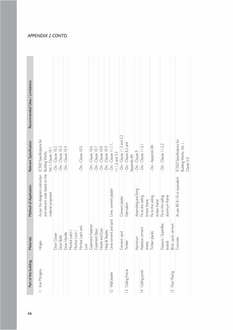
66
Part
of t
he b
uild
ing
Mat
erial
sM
etho
d of
App
licat
ion
Rele
vant
Spe
cifica
tion
Reco
mm
ende
d U
ses /
Lim
itatio
ns
11Iro
n M
onge
ryH
inges
As p
er th
e de
signe
rs in
struc
tion
ICTA
D S
pecif
icatio
ns fo
ran
d re
levan
t cod
e ba
sed
on th
eBu
ilding
Wor
ks,
mat
erial
pro
pose
dVo
l. I,
Clau
se 1
0.1
Doo
r Clo
ser
- Do
- Clau
se 1
0.2
Doo
r Bol
ts- D
o - C
lause
10.
3D
oor H
andl
e- D
o - C
lause
10.
4M
ortic
e La
tch
/M
ortic
e Lo
ck /
Mor
tice
Latc
h an
d- D
o - C
lause
10.
5Lo
ckC
asem
ent F
aste
ner
- Do
- Clau
se 1
0.6
Cas
emen
t Sta
ys- D
o - C
lause
10.
7H
ooks
and
Eye
s- D
o - C
lause
10.
8H
asp
& St
aples
- Do
- Clau
se 1
0.9
12W
all p
laste
rLim
e-ce
men
t and
sand
Lime,
cem
ent p
laste
r- D
o - C
lause
11.
1.1,
11.1
.2 a
nd 3
.3C
emen
t, sa
ndC
emen
t plas
ter
- Do
- Clau
se 1
1.3
and
3.2
13C
eiling
Fram
eTi
mbe
rFa
brica
tion
- Do
- Clau
se 8
.2 a
ndAp
pend
ix 8A
Alum
inum
Asse
mbl
ing an
d fix
ing- D
o - C
lause
914
Ceil
ing p
anel
Asbe
stos c
emen
tFix
to th
e ce
iling
- Do
- Clau
se 1
1.2.
1sh
eets
timbe
r fra
me
Tim
ber p
lanks
Fix to
the
ceilin
g- D
o - A
ppen
dix
8Atim
ber f
ram
eG
ypsu
m /
Supe
rflex
Fix to
the
ceilin
g- D
o - C
lause
11.
2.2
boar
dsalu
minu
m fr
ame
15Flo
or Pa
ving
Brick
, san
d, c
emen
tC
oncr
ete
As p
er B
S 81
10 o
r equ
ivalen
tIC
TAD
Spe
cifica
tions
for
Build
ing W
orks
, Vol
. I,
Clau
se 5
.0
APPENDIX 2 CONTD.

67
Part
of t
he b
uild
ing
Mat
erial
sM
etho
d of
App
licat
ion
Rele
vant
Spe
cifica
tion
Reco
mm
ende
d U
ses /
Lim
itatio
ns
16Flo
or fin
ishes
Cem
ent,
sand
Rend
ering
and
finish
ed sm
ooth
- Do
- Clau
se 1
1.3.
4/se
mi-r
ough
on
conc
rete
/bric
k pav
ingFlo
or ti
lesLa
y on
conc
rete
pav
ing- D
o - C
lause
11.
3.1
using
cem
ent g
rout
and
11.3
.8Ti
mbe
r flo
or d
eck
Plan
ks fix
ed to
the
timbe
r- D
o - C
lause
8.6
and
fram
eAp
pend
ix 8A
Terra
zzo
floor
finish
On
conc
rete
pav
ing- D
o - C
lause
11.
3.5
17Pa
inting
and
Dec
orat
ion
Lime
Whit
e / C
olor
was
h, a
pply
- Do
- Clau
se 1
4.1
and
14.2
of w
alls
with
a br
ush
Oil B
ound
Dist
empe
rAp
ply
one
coat
of p
rimer
- Do
- Clau
se 1
4.3
and
14.4
and
two
coat
s of D
istem
per
Cem
ent P
aint
Appl
y tw
o co
ats o
f Cem
ent P
aint-
Do
- Clau
se 1
4.5
and
14.6
Plas
tic E
muls
ion
Paint
Appl
y on
e co
at o
f prim
er- D
o - C
lause
14.
7 an
d 14
.8W
eath
er S
hield
pain
t sho
uld u
se fo
r ext
erna
l wall
san
d tw
o co
ats o
f pain
t18
Paint
ing an
d D
ecor
atio
nEn
amel
Paint
Appl
y on
e co
at o
f prim
er a
nd- D
o - C
lause
14.
9.1
of w
oodw
ork
two
coat
s of p
aint
and
14.9
.2Va
rnish
Appl
y on
e co
at o
f prim
er a
nd- D
o - C
lause
14.
10 a
nd 1
4.11
two
coat
s of p
aint
Fren
ch Po
lish
Appl
y th
ree
coat
of p
olish
- Do
- Clau
se 1
4.12
and
14.
1319
Paint
ing o
f Ste
el su
rface
sAn
ti-co
rrosiv
e Pa
intAp
ply
one
coat
of p
rimer
and
- Do
- Clau
se 1
4.9.
3 &
14.9
.4(p
rimer
) and
Ena
mel
two
coat
s of p
aint
Paint
20Pl
umbi
ng an
dU
PVC
wat
er su
pply
Refe
r BSC
P 31
2 - P
art 1
Sri L
anka
Spe
cifica
tion
for
Engin
eerin
g Ins
talla
tion
and
sew
erag
e pi
pes
and
BSC
P 30
5 - P
art 1
Build
ing W
orks
(Vol
ume
ll)–
Sanit
ary
Insta
llatio
n21
Inte
rnal
Wiri
ngPV
C c
ables
, PVC
Burie
d co
nduit
s or
Relev
ant P
S C
odes
, SLS
Cod
es,
cond
uits a
nd ac
cesso
ries,
Surfa
ce ca
sings
IEE
Wiri
ng R
egula
tions
-PV
C ca
sings
and
16th
Edi
tion
and
ICTA
Dac
cess
ories
, Sw
itche
s,Pu
blica
tion
SCA/
8 –
Aug.
200
0Pl
ugs a
nd so
cket
s,La
mps
, fitt
ings a
ndbu
lbs e
tc.

68
Bas
ic B
uild
ing
Mat
eria
lsPa
rt o
f the
bui
ldin
gM
ater
ials
Met
hod
of A
pplic
atio
nRe
leva
nt S
pecif
icatio
nRe
com
men
ded
Use
s / L
imita
tions
22C
emen
tO
rdina
ry P
ortla
ndAs
per
BS
12SL
S 10
7Fo
r any
cons
tructi
on ac
tivity
Cem
ent
Mas
onry
Cem
ent
Wall
plas
terin
gSL
S 51
5N
ot a
llow
ed to
be
use
for s
tructu
ral c
oncr
ete
wor
ks23
Lime
Lime
Wall
plas
terin
g, W
hite
/SL
S 55
2,C
olor
was
hIC
TAD
Spe
cifica
tions
for
Build
ing W
orks
, Vol
. I –
Clau
se 1
.622
Fine
aggr
egat
eRi
ver S
and
As p
er B
S 41
0 C
oncr
ete
wor
kIC
TAD
Spe
cifica
tions
for
Plas
terin
g &
Rend
ering
wor
kBu
ilding
Wor
ks, V
ol. I
–C
lause
1.6
Man
ufac
ture
d Sa
ndM
ason
ry w
ork,
conc
rete
wor
k,IC
TAD
Spe
cifica
tions
for
Usa
ge a
s per
the
prof
essio
nal a
dvise
(Cru
shed
Sto
ne S
and)
Plas
terin
g &
Rend
ering
wor
kBu
ilding
Wor
ks, V
ol. I
–C
lause
1.6
Pit S
and
Mas
onry
wor
k, C
oncr
ete
wor
k,IC
TAD
Spe
cifica
tions
for
Plas
terin
g &
Rend
ering
wor
kBu
ilding
Wor
ks, V
ol. I
–C
lause
1.6
Off S
hore
San
dM
ason
ry w
ork,
Con
cret
e w
ork,
- Do
- Clau
se 4
.1.3
.1,
Plas
terin
g &
Rend
ering
wor
kC
onfo
rm to
BS
882
23M
etal
Hot
-rolle
d M
S an
gles
BS 4
848
- Par
t 4IC
TAD
Spe
cifica
tions
for
Usa
ge a
s per
the
prof
essio
nal a
dvise
Build
ing W
orks
, Vol
. I–
Clau
se 9
.2 &
9.3
Hot
-rolle
d M
SSL
S 26
- Do
- Clau
se 5
.3ro
und
bars
Hot
-rolle
d hig
hBS
444
9yie
ld st
eel b
ars
Col
d w
orke
dSL
S 37
5de
form
ed st
eel b
ars
Har
d dr
awn
MS
wire
BS 4
482
Stee
l fabr
icSL
S 95
APPENDIX 2 CONTD.

69
NOTES

70
NOTES CONTD.