Embed Size (px)
Citation preview
DEVELOPMENT PLANNING & ENGINEERING
Development Engineering Section
Guidelines for Corridors and Corridor Crossings
QGL-CE-001

Guidelines for Corridors and Corridor Crossings
QGL–CE–001
Rev. No: 02
Draft No: Final
Date: 07-07-2014
Page No.: 1
Guidelines for Corridors and Corridor Crossings
QGL–CE–001
Rev. No: 02
Draft No: Final
Date: 07-07-2014
Page No.: 2
Foreword
Based on the decision taken during the Project Sub-Committee meeting of 5 July 2006, a “Crossing Agreement Task Force” was formed comprising of representatives from all the Stake Holders (QP, RLC and all the End Users). The terms of reference to the task force were as follows:
To discuss, define, prepare and formalize regulations and guidelines to be applied when Stake Holders assets cross, or are installed in proximity to, the assets of another Stake Holder, and ;
To prepare and propose a common technical Crossing requirement between Stake Holders to safeguard and prevent damage or interruption to facilities when crossings, or installations in proximity occur.
The task force members held several meetings, prepared detailed crossing requirements for each type of crossing and reviewed / debated all the individual crossing details. The efforts of the task force culminated in the form of preparing detailed drawings for all the crossing types. This Guideline supersedes and replaces the existing “Guidelines for Corridors and Corridor Crossings” vide document # QGL-RID-002 Rev.1.
Guidelines for Corridors and Corridor Crossings
QGL–CE–001
Rev. No: 02
Draft No: Final
Date: 07-07-2014
Page No.: 3
Contents Page No.
1.0 OBJECTIVES ............................................................................................................................................ 4
2.0 SCOPE ..................................................................................................................................................... 4
3.0 POLICY .................................................................................................................................................... 4
3.1 Basic Principles ........................................................................................................................... 4
3.2 Corridor Types ............................................................................................................................ 4
4.0 DEFINITIONS AND ABBREVIATIONS ....................................................................................................... 5
4.1 Abbreviations ............................................................................................................................. 5
5.0 RELATED DOCUMENTS ........................................................................................................................... 6
Other related documents: ..................................................................................................................... 6
6.0 PROCEDURE AND REQUIREMENTS ........................................................................................................ 7
6.1 Allocation of Space..................................................................................................................... 7
6.2 Submittal/Review Cycle ............................................................................................................. 7
6.3 Design Criteria ............................................................................................................................ 8
6.4 Drawing Criteria ......................................................................................................................... 9
6.5 Basic Installation Principles ...................................................................................................... 10
6.6 Crossing Corridors: ................................................................................................................... 13
7.0 RESPONSIBILITIES ................................................................................................................................. 22
7.1 QP-DC ....................................................................................................................................... 22
7.2 END USER ................................................................................................................................. 22
8.0 ATTACHMENTS ..................................................................................................................................... 23
8.1 Attachment 1 – Pipe/Utility Depth of Burial ............................................................................ 23
8.2 Attachment 2 – Crossing Clearances ....................................................................................... 23
8.3 Attachment 3: List of Typical Drawings ................................................................................... 25
Guidelines for Corridors and Corridor Crossings
QGL–CE–001
Rev. No: 02
Draft No: Final
Date: 07-07-2014
Page No.: 4
1.0 OBJECTIVES
The objectives of this document are to:
Acquaint End-Users and their contractors with QP-DC philosophy, regulations, and requirements for the installation of product pipelines, feedstock pipelines, distribution pipelines, utility pipelines, and other utilities in common corridors outside of the boundaries of leased sites.
Provide spacing requirements with respect to the crossing of roads, cables or pipelines by any above or underground utilities, cables or pipelines.
2.0 SCOPE
This document provides QP-DC specifications and requirements for installing pipelines and cables within QP-DC designated corridors. These requirements apply to all End-Users and contractors working at Ras Laffan Industrial City. The procedures for the assignment of corridor space to End-Users and clearances between pipelines over and below ground are also described.
3.0 POLICY
3.1 Basic Principles
Ras Laffan Industrial City is divided into several areas, each of which is to be utilized in a specific manner. QP-DC controls the use of the land within its boundaries in order to ensure efficiencies and to promote synergies. The length and breadth of the city have been demarcated and identified for specific functions, for example for purposes of communication by pipeline and/or cable between various areas within the city, such as from the plant site to the port.
End-Users and contractors are required to submit Technical details and method statements for review and approval as per Guideline for End User Technical Submissions to QP-DC (QGL-CE-002), prior to the submission of an application to perform the work. See Procedure for Use of the Consolidated Permit to Work for QP-DC Common Areas (QPR-RIE-010), referred below.
The submittals will be evaluated based upon the stipulations presented and discussed below and on conditions, existing or proposed, on the ground. And approval from asset holders shall be obtained before crossing any of their existing pipeline or utility.
3.2 Corridor Types
Guidelines for Corridors and Corridor Crossings
QGL–CE–001
Rev. No: 02
Draft No: Final
Date: 07-07-2014
Page No.: 5
Corridors are provided for the conveying of feedstock, product and utilities both above and underground:
3.2.1 Product Pipe Corridors provide space for pipelines to provide feedstock to processing plants, from plants via rundown pipelines to tank farms or the port for the storage and/or export of product, and for pipelines between End-Users. Pipelines in these corridors carry liquid products, primarily aboveground.
3.2.2 Wet Utility Corridors provide space for ‘wet’ utilities such as desalinated water, potable water,
irrigation water and seawater for back-up firewater. 3.2.3 Power Corridors provide space for high voltage and low voltage power cables. 3.2.4 High Pressure Gas Corridors provide space for pipelines containing gaseous and mixed phase feed
stocks and products. 3.2.5 Common Cooling Water Corridors provide space for seawater pipelines direct to End-Users & return
water pipelines from End-Users to outfalls channels, and sea water for back-up firewater. 3.2.6 Telecom Corridors provide space for End-Users, QP, or utility related telecom cables. 3.2.7 LNG Corridors provide space for End-User LNG run down pipelines to storage and / or vessel loading
facilities. These are collectively known as Service Corridors.
4.0 DEFINITIONS AND ABBREVIATIONS
This section contains definitions/acronyms which must be clearly understood by the document reader/audience.
4.1 Abbreviations
Abbreviation Definition
Depth of Burial Refers to the minimum depth to the top of the pipe/duct below FGL/NGL
End User A company or RLIC/MIC tenant that uses services, facilities and occupies land within RLIC/MIC premises.
FGL Finished Grade Level
HP High Pressure
NB Nominal Bore
NFA North Field Alpha
Guidelines for Corridors and Corridor Crossings
QGL–CE–001
Rev. No: 02
Draft No: Final
Date: 07-07-2014
Page No.: 6
Abbreviation Definition
NGL Natural / Existing Grade Level
PPC Product Pipe Corridors
QNHD Qatar National Height Datum
QP Qatar Petroleum
QP-DC Qatar Petroleum – Directorate of Industrial Cities
RLIC Ras Laffan Industrial City
TBD To Be Decided on case to case basis
5.0 RELATED DOCUMENTS
It is incumbent upon the End-User/ contractor to confirm that the latest revision of the Document/Regulation /Drawing is employed. All documents are available, upon written request, from QP-DC:
i. SK-RLC-00170- RLC Common Corridors key plan ii. QGL-CE-002 - Guideline for End User Technical Submissions to QP-DC
iii. SK-RLC-02319- RLIC Profile of Earthwork for Corridor Grading iv. SK-RLC-00163- RLC Utility Crossings and Pipe Culvert Details (Including Duct Bank Designs)
Other related documents:
i. QRG-DC-004 – Procedure and Regulation Governing Requirements for CPW in QP Industrial Cities Common Areas
ii. RLC/GL/002/2004 - Regulations for Colour Code Identification for Pipe Work in Ras Laffan Industrial City
iii. QGL-CE-004 - Guidelines for Site Grading and Drainage. iv. QGL-CE-006 - Guideline for Development of Roads in Ras Laffan Industrial City. v. QRG-DC-001 - Regulations for protection of overhead pipe bridges.
vi. QPR-DC-007 – Road Crossing Management Procedure vii. QP-PHL-S-001- QP Corporate Standard for Fire & Safety
viii. QGL-CE-009 - Design Guidelines for Road pavements ix. Environmental Regulations for Ras Laffan Industrial City x. Kahramaa’s guidelines “KM Regulations for Clearances and Works in the Vicinity of Extra-High
Voltage Installations”. xi. Q-Tel Publications Vol. 1, part 1 & 2 and Vol. 2, 3 and 4 for Underground Duct Laying. xii. Engineering Standard ES.5.14.051- Specification for Onshore Pipeline Construction.
Guidelines for Corridors and Corridor Crossings
QGL–CE–001
Rev. No: 02
Draft No: Final
Date: 07-07-2014
Page No.: 7
6.0 PROCEDURE AND REQUIREMENTS
6.1 Allocation of Space
Procedures and requirements for allocation of space to End-Users within Services Corridors are as follows:
6.1.1 Space in the Services Corridors to include QP-DC pipe racks on breakwaters, jetties or elsewhere will
be assigned on a first-come, first-served basis. End-Users, upon the approval of drawings, will enter into a lease agreement that will identify the specific space within a corridor that has been assigned to the End-User and will reserve that space for the End-User.
6.1.2 The space assigned above will be registered to grant a non-exclusive right of way upon, over, under and across QP-DC land, subject to such conditions as may be imposed.
6.1.3 Where an End-User requires additional space for other permanent uses, such as that required for a “safety margin”, then this space shall be included in the leased allotment (corridors). Temporary usage, such as during construction, will not be in the leased allotment.
6.1.4 Upon the expiry of a period of five (5) years, where the rights have not been exercised, and where there is no reasonable expectation that the space will be used in the foreseeable future, QP-DC reserves the right to enter into negotiations with the End-User to recover such land for use by other End-Users.
6.1.5 QP-DC will optimize the available space within corridors to provide for the long-term requirements of End-Users.
6.1.6 QP-DC will coordinate the interests of all the interested and/or affected parties in the installation of facilities and in the protection of End-Users and Qatar Petroleum (QP) assets.
6.1.7 Existing asset holders will cooperate with QP-DC to allow other End-Users to gain access to space in services corridors. Asset owner approval will be obtained for all crossings.
6.1.8 In response to a written request, QP-DC will supply all drawings that are required for the End-Users
to propose an allocation, on the basis that End-Users execute an original physical survey to establish the exact location of pipelines and utilities and the ownership of the assets.
6.1.9 Final drawings submitted to QP-DC shall comply with all relevant QP-DC requirements, including survey data that shall be in accordance with the CGIS-QNG 95 System.
6.1.10 In general, the End User must confine all their installations including the foundations, Safety margins etc., within the allotted space/ sub-corridor width.
6.2 Submittal/Review Cycle
Guidelines for Corridors and Corridor Crossings
QGL–CE–001
Rev. No: 02
Draft No: Final
Date: 07-07-2014
Page No.: 8
The submittal and review process is as follows:
6.2.1 End-Users will propose to route a pipeline or cable within a specific corridor.
6.2.2 There will be meetings/ discussions between QP-DC and the End-Users on the proposal.
6.2.3 QP-DC, in consultation with others if necessary, will review the proposal for approval.
6.2.4 End-Users will submit details/widths of the pipeline /cables crossings of other corridors, roads, or existing infrastructure.
6.2.5 After consultation with End-Users and/or others, QP-DC will review corridor widths for approval.
6.2.6 Following the approval, End-Users may then be advised by QP-DC of an exact location of the Corridor
assigned for their pipeline(s) / cable(s).
6.2.7 End-Users then submit this corridor with coordinates.
6.2.8 QP-DC will review this submittal for approval. When approved these drawings will be the basis for the Land Lease Agreement to be executed between the End-User and QP-DC and will be the basis for charging End-Users for space within the corridors.
6.3 Design Criteria
In evaluating drawings QP-DC will not scrutinize the technical engineering design, except with respect to optimising corridor space, and as necessary in its role as coordinator between different End-Users. QP-DC expects End-Users to be aware of and prepare submittals according to the following principles:
6.3.1 A route will approach a straight line between a point of supply and the point of delivery. This remains
the ideal. Designers are expected to consider all potential constraints in pipeline routing and recommend a feasible alternative that minimizes the consumption of land area, and minimizes disruption to other End-Users.
6.3.2 Levels are suggested in the preliminary QP-DC Grading and Drainage Plan and drawings, as mentioned above.
6.3.3 Aboveground, QP-DC requires the use of vertical expansion loops unless otherwise noted and agreed, and stipulates safe clearances between pipelines and utilities. See Table in Attachment 2.
6.3.4 Underground, QP-DC policy stipulates appropriate depths of burial, and criteria for crossings. See Table in Attachment 2.
Guidelines for Corridors and Corridor Crossings
QGL–CE–001
Rev. No: 02
Draft No: Final
Date: 07-07-2014
Page No.: 9
6.3.5 Standardized markings to identify pipelines and utilities are indicated in Regulations for Colour Code Identification for Pipe Work in Ras Laffan Industrial City (RLC/GL/002/2004) mentioned above and shall apply in all cases where pipelines are in common corridors.
6.3.6 Cables shall have concrete tile protection layer installed above with a warning tape layer and
aboveground markers indicating route location and width of the underground utility installation.
6.3.7 End-Users shall submit technical details and a method statement for review and approval as per Guidelines for End User Technical Submissions to QP-DC (QGL-CE-002). When approved these will be submitted with a Consolidated Permit to Work application prior to commencing work.
6.3.8 It is incumbent upon the End-User / Contractor to ensure that they are in possession of the Latest
Revision of regulations, documents, drawings, sketches, or other materials related to the work that may be required to inform and / or complement the work.
6.4 Drawing Criteria
Criteria for drawings to be submitted for approval to QP-DC are as follows:
6.4.1 The route of pipelines or cable from offshore to a plant site, and the route for the movement of products from one plant to another, a tank farm, or the port, either underground or aboveground, shall be clearly shown with co-ordinates based on the CGIS- QNG95 System.
6.4.2 The exact corridor layout, along with the details of the sleepers / pipe supports/duct banks/other
crossings, shall be incorporated in the RLC Common Corridors Key Plan (SK-RLC-00170) and shall be forwarded to QP-DC both in hard copy and Soft copy (AutoCAD ‘dwg’ format) in CGIS-QNG95 Co-ordinate system. This is necessary to ascertain the actual location of the corridors and to carry out any interference check with other corridors/crossings.
6.4.3 The Approved for Construction (AFC) drawings followed by As-built drawings of all installed pipelines and other facilities shall be provided to QP-DC in AutoCAD ‘dwg’ format that conforms to the QP-DC system. All plan drawings shall be made in CGIS-QNG 95 Co-ordinate system.
6.4.4 Cross sections shall be shown of all pipelines and utilities entering and exiting the site, and along the route, at every point where new pipes are branching into or off the main route crossing roadways, other rights- of –way or other utility or product corridors.
6.4.5 A list of crossings shall be shown which shall be numbered, and the design solution shall be provided
in each case where a road or another pipeline/utility or facility or a corridor is affected, or any other complication that would require attention. This list should be part of the FEED document.
6.4.6 The corridor cross sections shall show the following as a minimum:
Guidelines for Corridors and Corridor Crossings
QGL–CE–001
Rev. No: 02
Draft No: Final
Date: 07-07-2014
Page No.: 10
(i) Composite details of the installed infrastructure (sleepers, cables, pipelines, etc) and both edges of the corridor and sub corridor;
(ii) Centre line distances between pipelines and utilities;
(iii) The horizontal clearances between pipelines and utilities;
(iv) Vertical clearances in case of pipelines and/or utilities crossing each other;
(v) In case of an insulated pipeline, the thickness of insulation shall be noted;
(vi) Natural ground level based on QNHD;
(vii) Finished grade level based on QNHD;
(viii) Water table;
(ix) Depth of burial (i.e. top of the pipe/duct below FGL/NGL);
(x) Top or invert of pipe based on QNHD.
6.5 Basic Installation Principles
Refer to Attachment 1 for depth of burial and Refer to Attachment 2 for crossing requirements in all cases when crossing corridors.
6.5.1 Product Pipe Corridors
6.5.1.1 Product Pipe Corridors (PPC) are for the movement of Hydrocarbons, and other liquid products within the Ras Laffan Industrial City.
6.5.1.2 The piping systems are normally aboveground. 6.5.1.3 PPC usage may also include control cables for the pipelines within the corridors. 6.5.1.4 End-Users receive an easement (sub corridor) within the Product Pipeline Corridor as part
of their land lease. An easement is a right to use the leased land. QP-DC remains the holder of the property.
6.5.1.5 End-Users’ pipelines and cabling might share the same pipe way, and the width of the pipe way shall be minimized. The total width of a sub-corridor will be less than 10m for a maximum over reach of 5m from each side.
6.5.1.6 QP-DC requires that all expansion loops be vertical. No loops, anchor blocks, valve pits etc. shall be located in crossing locations.
6.5.1.7 Pipeline bridge foundation locations are to be approved by QP-DC and will have approximately 15m spans (depending on the type of crossing this span may vary).
6.5.1.8 In general, the End User must confine all their installations including the foundations, Safety margins etc., within the allotted space/ sub-corridor width.
Guidelines for Corridors and Corridor Crossings
QGL–CE–001
Rev. No: 02
Draft No: Final
Date: 07-07-2014
Page No.: 11
6.5.2 Wet Utility Corridors
6.5.2.1 Includes potable water, desalinated water, back up fire water, treated industrial water and irrigation water.
6.5.2.2 Wet utilities are typically installed underground, except back up firewater system Phase-1,
which is installed aboveground.
6.5.2.3 Pipelines shall have a minimum cover of 1.0m from either FGL or NGL, whichever is lower.
6.5.2.4 No anchor blocks, valve pits etc. shall be located in crossing locations.
6.5.2.5 Pipeline markers shall be installed at following locations as a minimum, to indicate details of underground facility such as type of the utility, route location, depth from NGL or FGL etc. a. Every 100m (maximum) b. Changes in direction c. Coupling positions d. Drain & vent locations e. Start and finish points of all crossing locations.
6.5.3 Power Corridors 6.5.3.1 Typically underground and refer to both high and low voltage underground cables. 6.5.3.2 Cables shall have a minimum cover of 1.1m from either FGL or NGL, whichever is lower. 6.5.3.3 Adequate protection in the form of duct banks shall be provided for power cables while
crossing the Road/ Maintenance track/ Access track. 6.5.3.4 At least 100 percent or 6 sleeves shall be provided as spares, for QP-DC’s future usage,
when crossing roads. 6.5.3.5 Cables will have concrete tile protection layer installed above with a warning tape layer and
aboveground markers indicating route location, type of utility, depth/ width of the underground utility installation etc. The markers shall be installed at following locations, as a minimum, as per QP Engineering Standard for Electrical Cable Marker Post (drawing No. ES.2.62.0016). a. Every 50m (maximum) b. Splice position c. Changes in direction d. Start and finish points of all crossing locations
6.5.3.6 End User cables shall have no servicing points or joint bays within any other corridor crossing area. All such joint bays/servicing points shall be located in straight corridor runs within the power corridor area and shall be clear of any crossing area.
Guidelines for Corridors and Corridor Crossings
QGL–CE–001
Rev. No: 02
Draft No: Final
Date: 07-07-2014
Page No.: 12
6.5.4 High Pressure Gas Corridors 6.5.4.1 Pipelines will be underground; Pipelines shall be bunded. 6.5.4.2 Minimum cover shall be 1.5m from FGL or NGL, whichever is lower. 6.5.4.3 Access over pipeline shall be provided every 1000m or at the location of exiting access roads
or approximation thereof wherever deemed necessary with adequate protection for the Underground pipe(s).
6.5.4.4 Minimum separation from any existing parallel facilities adjacent to the HP Gas Corridor or from an existing buried pipeline within the HP gas corridor shall be 5.0m; this shall be subject to approval of the applicable asset owner, wherever required.
6.5.4.5 Where the new pipeline is laid near the existing one in the same trench, the minimum clearance shall be one meter (1m) or twice the outer diameter (2 x O.D) of the larger pipe, whichever is higher.
6.5.4.6 No additional width will be granted to accommodate possible additional depth required in crossings.
6.5.4.7 Pipeline markers shall be installed as vide QP Standard No. ES.5.14.0051-Specification for Onshore Pipeline Construction, referred above.
6.5.4.8 Adequate protection in the form of a duct bank or concrete slab shall be provided while crossing the Maintenance/Access Road.
6.5.5 Cooling Water Corridors
6.5.5.1 Cooling water corridors are for QP-DC seawater cooling supply and return pipes. Cooling water is supplied by QP-DC to the End-Users.
6.5.5.2 Pipelines may be above or below ground as determined by the Projects 6.5.5.3 Where excavation above the Cooling Water line is required, such excavation shall not be
more than 10m at a time along the length of the pipeline.
6.5.6 Telecom Cable / Duct Banks
6.5.6.1 Cables shall be installed in underground ducts at a minimum cover of 0.6m from FGL or NGL whichever is lower.
6.5.6.2 Cables shall be installed in duct banks at road crossings. 6.5.6.3 Duct bank burial and configuration will be consistent with Ooreedo/any future telecom
service provider requirements. Ooreedo Publications for Underground Duct Laying Vol. 1, part 1 & 2 and Vol. 2, 3 and 4 shall be referred.
6.5.6.4 QP-DC Telecom Department will coordinate with Ooreedo/ any future telecom service provider and End-Users during design and construction of the installation.
6.5.7 LNG Corridor
6.5.7.1 LNG Corridors will contain insulated LNG rundown & associated pipelines and associated cabling.
6.5.7.2 Expansion loops will typically be horizontal and will be “nested" to the extent possible. 6.5.7.3 LNG pipelines will be above grade.
Guidelines for Corridors and Corridor Crossings
QGL–CE–001
Rev. No: 02
Draft No: Final
Date: 07-07-2014
Page No.: 13
6.6 Crossing Corridors: The basic philosophy to be adopted while developing a crossing detail is depicted below.
6.6.1 Crossing Product Pipe Corridors 6.6.1.1 Product pipes shall cross at a minimum of 5.5m above FGL or 3m above the top of the
product pipes whichever is higher. 6.6.1.2 Wet utilities pipelines shall cross 2.0m below FGL. 6.6.1.3 Underground power cables shall cross 2.0m below FGL. 6.6.1.4 HP gas pipelines shall cross 2.0m below FGL. 6.6.1.5 Cooling water (Aboveground) pipelines shall cross above grade at FGL. 6.6.1.6 Cooling water pipelines (Underground) shall cross at 2.0m below FGL. 6.6.1.7 Telecom ducts shall cross 0.6m (min.) below FGL. 6.6.1.8 LNG pipelines shall cross above grade at FGL. 6.6.1.9 Permanent access roads shall cross existing facilities in the Product Pipe Corridor with a
culvert or other suitable protections set by the asset owner.
6.6.2 Crossing Wet Utility Corridors
6.6.2.1 Product pipelines shall cross above grade at FGL with Duct Bank Type # 9 at 2.0m below FGL for the existing and future wet utility pipes.
6.6.2.2 Wet utilities pipelines: a. In general, wet utility pipelines shall cross a wet utility corridor at the same elevation as
the existing parallel wet utility pipeline wherever applicable. b. Wet utility pipelines shall cross an unoccupied Wet Utility corridor at minimum 1.0m
below NGL or FGL whichever is lower. c. Wet utility pipelines shall cross an occupied Wet Utility corridor at either 1.0m or 2.5m
below NGL or FGL whichever is lower depending on the depth of the pipeline in the corridor that needs to be crossed.
6.6.2.3 Underground power cables: a. In general, power cables shall cross a Wet Utility corridor at the same elevation as the
existing parallel power cables wherever applicable. b. Power cables shall cross an unoccupied Wet Utility corridor at minimum 2.5m below
NGL or FGL whichever is lower. c. Power cables shall cross an occupied Wet Utility corridor at either 2.5m below NGL/ FGL
or 600mm below the existing wet utility pipeline whichever lower, depending on the depth of the pipeline in the corridor that needs to be crossed.
6.6.2.4 HP gas pipelines shall cross at 2.5m below the lowest of FGL or NGL. 6.6.2.5 Cooling water pipelines (Aboveground) shall cross above grade at FGL with suitable sleeper
supports outside the Wet Utility Corridors with a Duct Bank Type # 9. 6.6.2.6 Common Cooling Water Pipelines (Underground)
Guidelines for Corridors and Corridor Crossings
QGL–CE–001
Rev. No: 02
Draft No: Final
Date: 07-07-2014
Page No.: 14
a. In general, cooling water pipelines (Underground) shall cross a Wet Utility corridor at the same elevation as the existing parallel Cooling Water pipelines wherever applicable.
b. Cooling water pipelines (Underground) shall cross an unoccupied Wet Utility corridor at minimum 1m below FGL.
c. Cooling water pipelines (Underground) shall cross an occupied Wet Utility corridor at; - 2.5m below FGL, -or at a depth of 600mm below the existing Wet Utility pipeline, -or above grade at FGL.
6.6.2.7 Telecom ducts shall cross at 0.6m (min.) below the lowest of FGL or NGL. 6.6.2.8 LNG pipelines shall cross above grade at FGL with Duct Bank Type # 9. 6.6.2.9 Permanent Access Roads shall cross with a Duct Bank Type # 9 for the existing and future
wet utility pipelines. 6.6.2.10 General:
a. New ducts within the corridors shall be aligned with existing duct banks, and the pull cords shall be replaced with longer pull cords.
b. Wet Utility Corridors shall have a duct bank for the full width of the Wet Utility corridor crossing - QP-DC Duct Bank Type # 9, placed below the End-User’s portion of the corridor.
c. Where there are existing pipelines, the End-Users shall provide split sleeves prior to pouring the concrete to form a duct bank.
6.6.3 Crossing Underground Power Corridors 6.6.3.1 Product pipes shall cross above grade at FGL with Duct Bank Type # 8 at 2.0m below FGL
for cables. 6.6.3.2 Wet utilities pipelines:
a. In general, wet utility pipelines shall cross a Power corridor at the same elevation as the existing parallel wet utility pipeline wherever applicable.
b. Wet utility pipelines shall cross an unoccupied Power corridor at minimum 1.0m below NGL or FGL whichever is lower.
c. Wet utility pipelines shall cross an occupied Power corridor at either 1.0m or 2.0m below NGL or FGL whichever is lower depending on the depth of the power cables in the corridor that needs to be crossed.
6.6.3.3 Underground Power cables: a. In general, power cables shall cross a Power corridor at the same elevation as the
existing parallel power cables wherever applicable. b. Power cables shall cross an unoccupied Power corridor at minimum 1.1m below NGL or
FGL whichever is lower. c. Power cables shall cross an occupied Power corridor at either 1.1m or 2.0m below NGL
or FGL whichever is lower depending on the depth of the power cables in the corridor that needs to be crossed.
6.6.3.4 HP gas pipelines shall cross at 2.0m below the lowest of FGL or NGL. 6.6.3.5 Cooling water pipelines (Aboveground) shall cross above grade at FGL with suitable sleeper
supports as agreed by QP-DC with Duct Bank Type # 8 for power cables.
Guidelines for Corridors and Corridor Crossings
QGL–CE–001
Rev. No: 02
Draft No: Final
Date: 07-07-2014
Page No.: 15
6.6.3.6 Cooling Water Pipelines (Underground) a. In general, cooling water pipelines (Underground) shall cross a Power corridor at the
same elevation as the existing parallel Cooling Water pipelines wherever applicable. b. Cooling water pipelines (Underground) shall cross an unoccupied Power corridor at
minimum 1.0m below FGL /NGL whichever is lower. c. Cooling water pipelines (Underground) shall cross an occupied Power corridor at 2.0m
below FGL /NGL whichever is lower.
6.6.3.7 Telecom ducts shall cross at 0.6m (min.) below the lowest of FGL or NGL. 6.6.3.8 LNG pipe lines shall cross above grade at FGL and install Duct Bank Type # 8 for the power
cables. 6.6.3.9 Permanent Access roads shall cross with a Duct Bank Type # 8 for the existing and future
Power cables 6.6.3.10 General:
a. Power Corridors shall have a duct bank for the full width of the Power corridor crossing - QP-DC Duct Bank Type # 8, placed below the End-User’s portion of the corridor.
b. New ducts within the corridor shall be aligned with existing duct banks, or cables and the pull cords shall be replaced with longer pull cords.
c. Where there are existing cables, the End-Users shall provide split sleeves prior to pouring the concrete to form a duct bank.
6.6.4 Crossing Kahramaa Power Corridors
6.6.4.1 Where there are Underground Power Cables (66kV, 132kV, 220 kV, 400kV) the location of the pipe supports within them shall be determined in consultation with Kahramaa and QP-DC.
6.6.4.2 When crossing Overhead Power Transmission Tower Corridors, pipeline installation shall be constructed with low lift equipment.
6.6.4.3 Necessary Telltale system (TTS) as per QP-DC document No. QRG-RID-002 to be provided for crossing the existing overhead Power Transmission lines.
6.6.4.4 Kahramaa’s access road will be maintained and no pipelines shall be closer than 25.0m from installed structures.
6.6.4.5 Crossings will be reviewed for approval by Kahramaa. 6.6.4.6 Kahramaa’s guidelines “KM Regulations for Clearances and Works in the Vicinity of Extra-
High Voltage Installations” shall be referred and followed. Approvals from Kahramaa shall be obtained for all the crossings, as set out in this document.
6.6.5 Crossing HP Gas Corridors 6.6.5.1 Product pipelines shall cross above grade at FGL. 6.6.5.2 Wet utilities pipelines shall cross 1.0m below the lowest of FGL or NGL.
Guidelines for Corridors and Corridor Crossings
QGL–CE–001
Rev. No: 02
Draft No: Final
Date: 07-07-2014
Page No.: 16
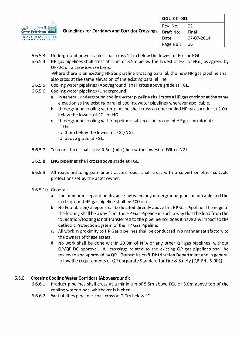
6.6.5.3 Underground power cables shall cross 1.1m below the lowest of FGL or NGL. 6.6.5.4 HP gas pipelines shall cross at 1.5m or 3.5m below the lowest of FGL or NGL, as agreed by
QP-DC on a case-to-case basis. Where there is an existing HPGas pipeline crossing parallel, the new HP gas pipeline shall also cross at the same elevation of the existing parallel line.
6.6.5.5 Cooling water pipelines (Aboveground) shall cross above grade at FGL. 6.6.5.6 Cooling water pipelines (Underground):
a. In general, underground cooling water pipeline shall cross a HP gas corridor at the same elevation as the existing parallel cooling water pipelines wherever applicable.
b. Underground cooling water pipeline shall cross an unoccupied HP gas corridor at 1.0m below the lowest of FGL or NGL
c. Underground cooling water pipeline shall cross an occupied HP gas corridor at; -1.0m, -or 3.5m below the lowest of FGL/NGL, -or above grade at FGL.
6.6.5.7 Telecom ducts shall cross 0.6m (min.) below the lowest of FGL or NGL.
6.6.5.8 LNG pipelines shall cross above grade at FGL.
6.6.5.9 All roads including permanent access roads shall cross with a culvert or other suitable protections set by the asset owner.
6.6.5.10 General: a. The minimum separation distance between any underground pipeline or cable and the
underground HP gas pipeline shall be 600 mm. b. No Foundation/sleeper shall be located directly above the HP Gas Pipeline. The edge of
the footing shall be away from the HP Gas Pipeline in such a way that the load from the foundation/footing is not transferred to the pipeline nor does it have any impact to the Cathodic Protection System of the HP Gas Pipeline.
c. All work in proximity to HP Gas pipelines shall be conducted in a manner satisfactory to the owners of these assets.
d. No work shall be done within 20.0m of NFA or any other QP gas pipelines, without QP/QP-DC approval. All crossings related to the existing QP gas pipelines shall be reviewed and approved by QP – Transmission & Distribution Department and in general follow the requirements of QP Corporate Standard for Fire & Safety (QP-PHL-S-001).
6.6.6 Crossing Cooling Water Corridors (Aboveground):
6.6.6.1 Product pipelines shall cross at a minimum of 5.5m above FGL or 3.0m above top of the cooling water pipes, whichever is higher.
6.6.6.2 Wet utilities pipelines shall cross at 2.0m below FGL
Guidelines for Corridors and Corridor Crossings
QGL–CE–001
Rev. No: 02
Draft No: Final
Date: 07-07-2014
Page No.: 17
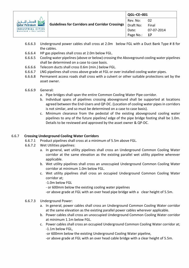
6.6.6.3 Underground power cables shall cross at 2.0m below FGL with a Duct Bank Type # 8 for the cables.
6.6.6.4 HP gas pipelines shall cross at 2.0m below FGL. 6.6.6.5 Cooling water pipelines (above or below) crossing the Aboveground cooling water pipelines
shall be determined on a case to case basis. 6.6.6.6 Telecom ducts shall cross 0.6m (min.) below FGL. 6.6.6.7 LNG pipelines shall cross above grade at FGL or over installed cooling water pipes. 6.6.6.8 Permanent access roads shall cross with a culvert or other suitable protections set by the
asset owner.
6.6.6.9 General: a. Pipe bridges shall span the entire Common Cooling Water Pipe corridor. b. Individual spans of pipelines crossing aboveground shall be supported at locations
agreed between the End-Users and QP-DC. (Location of cooling water pipes in corridors is not similar, and so must be determined on a case to case basis).
c. Minimum clearance from the pedestal of the existing aboveground cooling water pipelines to any of the future pipeline/ edge of the pipe bridge footing shall be 1.0m. Details to be reviewed and approved by the asset owner & QP-DC.
6.6.7 Crossing Underground Cooling Water Corridors 6.6.7.1 Product pipelines shall cross at a minimum of 5.5m above FGL. 6.6.7.2 Wet Utilities pipelines:
a. In general, wet utility pipelines shall cross an Underground Common Cooling Water corridor at the same elevation as the existing parallel wet utility pipeline wherever applicable.
b. Wet utility pipelines shall cross an unoccupied Underground Common Cooling Water corridor at minimum 1.0m below FGL.
c. Wet utility pipelines shall cross an occupied Underground Common Cooling Water corridor at; -1.0m below FGL - or 600mm below the existing cooling water pipelines -or above grade at FGL with an over head pipe bridge with a clear height of 5.5m.
6.6.7.3 Underground Power: a. In general, power cables shall cross an Underground Common Cooling Water corridor
at the same elevation as the existing parallel power cables wherever applicable. b. Power cables shall cross an unoccupied Underground Common Cooling Water corridor
at minimum 1.1m below FGL. c. Power cables shall cross an occupied Underground Common Cooling Water corridor at;
-1.1m below FGL, -or 600mm below the existing Underground Cooling Water pipeline, -or above grade at FGL with an over head cable bridge with a clear height of 5.5m.
Guidelines for Corridors and Corridor Crossings
QGL–CE–001
Rev. No: 02
Draft No: Final
Date: 07-07-2014
Page No.: 18
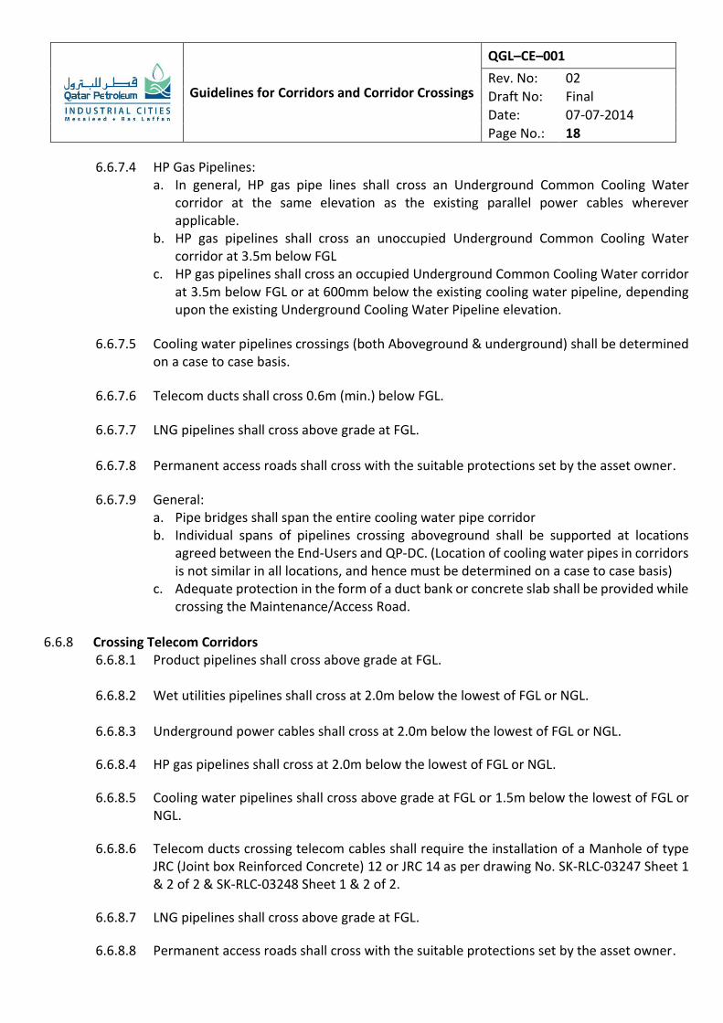
6.6.7.4 HP Gas Pipelines: a. In general, HP gas pipe lines shall cross an Underground Common Cooling Water
corridor at the same elevation as the existing parallel power cables wherever applicable.
b. HP gas pipelines shall cross an unoccupied Underground Common Cooling Water corridor at 3.5m below FGL
c. HP gas pipelines shall cross an occupied Underground Common Cooling Water corridor at 3.5m below FGL or at 600mm below the existing cooling water pipeline, depending upon the existing Underground Cooling Water Pipeline elevation.
6.6.7.5 Cooling water pipelines crossings (both Aboveground & underground) shall be determined on a case to case basis.
6.6.7.6 Telecom ducts shall cross 0.6m (min.) below FGL.
6.6.7.7 LNG pipelines shall cross above grade at FGL.
6.6.7.8 Permanent access roads shall cross with the suitable protections set by the asset owner.
6.6.7.9 General: a. Pipe bridges shall span the entire cooling water pipe corridor b. Individual spans of pipelines crossing aboveground shall be supported at locations
agreed between the End-Users and QP-DC. (Location of cooling water pipes in corridors is not similar in all locations, and hence must be determined on a case to case basis)
c. Adequate protection in the form of a duct bank or concrete slab shall be provided while crossing the Maintenance/Access Road.
6.6.8 Crossing Telecom Corridors
6.6.8.1 Product pipelines shall cross above grade at FGL.
6.6.8.2 Wet utilities pipelines shall cross at 2.0m below the lowest of FGL or NGL.
6.6.8.3 Underground power cables shall cross at 2.0m below the lowest of FGL or NGL.
6.6.8.4 HP gas pipelines shall cross at 2.0m below the lowest of FGL or NGL.
6.6.8.5 Cooling water pipelines shall cross above grade at FGL or 1.5m below the lowest of FGL or NGL.
6.6.8.6 Telecom ducts crossing telecom cables shall require the installation of a Manhole of type JRC (Joint box Reinforced Concrete) 12 or JRC 14 as per drawing No. SK-RLC-03247 Sheet 1 & 2 of 2 & SK-RLC-03248 Sheet 1 & 2 of 2.
6.6.8.7 LNG pipelines shall cross above grade at FGL.
6.6.8.8 Permanent access roads shall cross with the suitable protections set by the asset owner.
Guidelines for Corridors and Corridor Crossings
QGL–CE–001
Rev. No: 02
Draft No: Final
Date: 07-07-2014
Page No.: 19
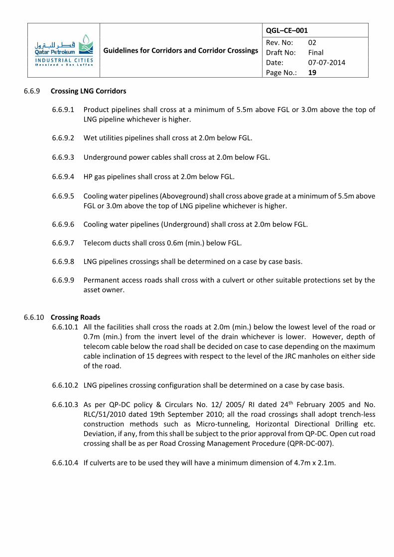
6.6.9 Crossing LNG Corridors
6.6.9.1 Product pipelines shall cross at a minimum of 5.5m above FGL or 3.0m above the top of LNG pipeline whichever is higher.
6.6.9.2 Wet utilities pipelines shall cross at 2.0m below FGL.
6.6.9.3 Underground power cables shall cross at 2.0m below FGL.
6.6.9.4 HP gas pipelines shall cross at 2.0m below FGL.
6.6.9.5 Cooling water pipelines (Aboveground) shall cross above grade at a minimum of 5.5m above FGL or 3.0m above the top of LNG pipeline whichever is higher.
6.6.9.6 Cooling water pipelines (Underground) shall cross at 2.0m below FGL.
6.6.9.7 Telecom ducts shall cross 0.6m (min.) below FGL.
6.6.9.8 LNG pipelines crossings shall be determined on a case by case basis.
6.6.9.9 Permanent access roads shall cross with a culvert or other suitable protections set by the asset owner.
6.6.10 Crossing Roads 6.6.10.1 All the facilities shall cross the roads at 2.0m (min.) below the lowest level of the road or
0.7m (min.) from the invert level of the drain whichever is lower. However, depth of telecom cable below the road shall be decided on case to case depending on the maximum cable inclination of 15 degrees with respect to the level of the JRC manholes on either side of the road.
6.6.10.2 LNG pipelines crossing configuration shall be determined on a case by case basis.
6.6.10.3 As per QP-DC policy & Circulars No. 12/ 2005/ RI dated 24th February 2005 and No. RLC/51/2010 dated 19th September 2010; all the road crossings shall adopt trench-less construction methods such as Micro-tunneling, Horizontal Directional Drilling etc. Deviation, if any, from this shall be subject to the prior approval from QP-DC. Open cut road crossing shall be as per Road Crossing Management Procedure (QPR-DC-007).
6.6.10.4 If culverts are to be used they will have a minimum dimension of 4.7m x 2.1m.
Guidelines for Corridors and Corridor Crossings
QGL–CE–001
Rev. No: 02
Draft No: Final
Date: 07-07-2014
Page No.: 20
6.6.10.5 Open trench crossings when approved shall be done in two halves with separate diversion agreements.
6.6.10.6 Provision shall be left in the underground structure for drainage as well as drainage pumps
if applicable. Space may be provided for additional pipelines and cables.
6.6.10.7 The crossing shall be designed for the axle loads as per the ‘Design Guidelines for Road Pavements (QGL-CE-009)’.
6.6.10.8 Sleeves shall be used wherever necessary.
6.6.11 Crossing Storm Water Drains & Outfalls
6.6.11.1 Product pipelines shall cross at a minimum of 5.5m above FGL.
6.6.11.2 Wet utilities pipelines shall cross at 0.7m below the invert level of the drain.
6.6.11.3 Underground power cables shall cross at 0.5m below invert level of the drain with the Duct Bank Type # 8
6.6.11.4 HP gas pipelines shall cross 0.7m below invert level of the drain with necessary protection as set by RLC & the asset owner.
6.6.11.5 Cooling water pipelines shall cross above grade at a minimum of 5.5m above FGL or at 0.7m below invert level of the drain with protection set by QP-DC and the asset owner. Crossing details to be decided on case to case basis.
6.6.11.6 Telecom ducts shall cross at 0.5m below the invert level of the drain with telecom duct bank.
6.6.11.7 LNG pipelines shall cross above grade on sleepers.
6.6.11.8 Permanent access roads shall cross with a drainage culvert for the exiting storm water drains, outfalls, etc.
6.6.12 General
6.6.12.1 While installing duct banks, the new duct bank shall match with the existing duct bank both in elevation and alignment. Also the existing pull cords shall be suitability extended/replaced with sufficiently long cord.
6.6.12.2 Where there are existing assets, the End Users shall be responsible to protect the existing
underground utilities using concrete slabs, split sleeve duct banks etc. or other suitable protections set by the asset owner.
Guidelines for Corridors and Corridor Crossings
QGL–CE–001
Rev. No: 02
Draft No: Final
Date: 07-07-2014
Page No.: 21
6.6.12.3 All work in the proximity to HP gas pipelines shall be conducted in a manner satisfactory to the Owner of the assets. Similarly, excavations when carried out within 3m from any adjacent underground live facility shall be carried out by Manual Excavations only.
6.6.12.4 No work shall be done within 20.0m of NFA or any other QP Gas Pipe Lines, without QP/QP-DC prior approval. All crossing details and Method Statement related to the existing / proposed QP Gas Pipelines shall be reviewed and approved by QP – Transmission & Distribution (TD) Department and in general follow the requirements of QP Corporate Standard for Fire & Safety (QP-PHL-S-001).
6.6.12.5 Pipe bridges for Cooling Water Pipe Corridors shall span the entire width of the Corridor. Individual spans of the pipelines crossing the cooling water pipe corridors aboveground / underground shall be supported at locations agreed between the End User and QP-DC. (Location of the Cooling water pipelines in the corridors are not similar in all locations and hence support locations shall be finalized on case to case basis.).
6.6.12.6 Necessary Telltale System (TTS) shall be provided to protect the End User’s pipe or cable bridges by the End User/ Contractor, as per QP-DC document No.“QRG-DC-002- Regulations for protection of overhead pipe bridges”.
6.6.12.7 Expansions loops, Anchor blocks, Telecom manholes, Valve pits etc. shall not be located at crossing locations.
6.6.12.8 QP-DC will undertake periodical cleaning/ maintenance of the storm water drain below the crossing locations. It will be the responsibility of relevant End User/ asset owner to provide expeditious concurrence when notified by QP-DC.
6.6.13 Management of Crossings 6.6.13.1 The following methodology of managing crossings is suggested to ensure that all Crossings
are identified and managed properly. This Crossing Register / Crossing Matrix shall be submitted to QP-DC prior to forwarding the detailed crossing drawings.
6.6.13.2 This Crossing Register / Matrix will be reviewed and approved by QP-DC along with the overall corridor drawing indicating all these crossings.
6.6.13.3 Separate drawings shall be prepared for each of these crossings and shall be submitted to
QP-DC for review and approval.
6.6.13.4 The Crossing Register shall contain the following information, as minimum: (i) Define a Crossing Area:
This is the area created by the intersection of a Corridor with another Corridor/Service. All such Crossings shall be identified in a plan drawing, after obtaining the latest As-Built / Proposed design/FEED drawings and as per site survey
Guidelines for Corridors and Corridor Crossings
QGL–CE–001
Rev. No: 02
Draft No: Final
Date: 07-07-2014
Page No.: 22
data collection. QP-DC’s latest revision of the Consolidated Common Corridors Key Plan Drawing # SK-RLC-00170 shall be utilized for this purpose.
(ii) Create a Crossing Register: Create a Crossing register which depicts the true status of a given crossing area and helps in maintaining and updating the updated status of all such crossings a. Identify all services that are currently present in a crossing area, if no service
exists label it as ‘No Identified Service’ b. Identify all the asset owners/end-users for all such existing/proposed (under
planning or FEED or EPC). c. Identify all the concurrent parties working at the same area. d. Identify all the Concurring parties for the Crossing. e. Include the List of As-Built drawings / Design drawings of all the
existing/proposed services of all the Concurring parties. f. Indicate the drawing numbers of the crossing and the status of their revision. g. Name & Number all the Crossings in an orderly & sequential way
7.0 RESPONSIBILITIES
This section highlights the key responsibilities of parties directly involved in the process described by the document.
7.1 QP-DC
7.1.1 QP-DC is responsible for assigning corridor space to End-User upon receipt of the relevant documentation and issuing necessary approvals.
7.1.2 Upon written request QP-DC will provide up-to-date drawings as referred to in Section 4.0
7.1.3 QP-DC is responsible for updating information included in this document.
7.2 END USER
7.2.1 End-Users are required to adhere to the relevant requirements depicted in this document and to other codes, guidelines and regulations applicable for the job depending upon the nature of the job and project requirements.
Guidelines for Corridors and Corridor Crossings
QGL–CE–001
Rev. No: 02
Draft No: Final
Date: 07-07-2014
Page No.: 23
8.0 ATTACHMENTS
8.1 Attachment 1 – Pipe/Utility Depth of Burial Table 1 indicates minimum depth of burial within corridors. The dimensions given below are measured in meters, unless otherwise indicated.
Table 1: Pipeline/Utility Depth of Burial from FGL / NGL
(Non Crossing Areas)
Power 1.1m
Wet Utility 1.0m
HP Gas Line 1.5m
Telecom 0.6m (min)
Cooling Water (Underground)
1.0m (min.)
8.2 Attachment 2 – Crossing Clearances
Table 2, shown in the following page, provides the minimum clearances required for the utilities/pipelines and cables installed in various corridors when crossing other corridors. The dimensions given in the Table are measured in meters and are the minimum cover or height measured from FGL/NGL, unless otherwise indicated. Note: Crossings will be submitted to QP-DC for review and approval. Dimensions / stipulations may vary depending upon the existing situation on the ground.
Guidelines for Corridors and Corridor Crossings
QGL–CE–001
Rev. No: 02
Draft No: Final
Date: 07-07-2014
Page No.: 24
Attach Table No.2
Guidelines for Corridors and Corridor Crossings
QGL–CE–001
Rev. No: 02
Draft No: Final
Date: 07-07-2014
Page No.: 25
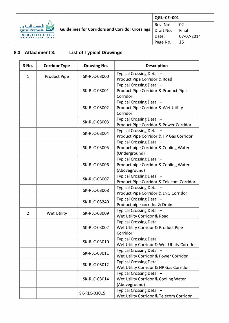
8.3 Attachment 3: List of Typical Drawings
S No. Corridor Type Drawing No. Description
1 Product Pipe SK-RLC-03000 Typical Crossing Detail – Product Pipe Corridor & Road
SK-RLC-03001 Typical Crossing Detail – Product Pipe Corridor & Product Pipe Corridor
SK-RLC-03002 Typical Crossing Detail – Product Pipe Corridor & Wet Utility Corridor
SK-RLC-03003 Typical Crossing Detail – Product Pipe Corridor & Power Corridor
SK-RLC-03004 Typical Crossing Detail – Product Pipe Corridor & HP Gas Corridor
SK-RLC-03005 Typical Crossing Detail – Product pipe Corridor & Cooling Water (Underground)
SK-RLC-03006 Typical Crossing Detail – Product pipe Corridor & Cooling Water (Aboveground)
SK-RLC-03007 Typical Crossing Detail – Product Pipe Corridor & Telecom Corridor
SK-RLC-03008 Typical Crossing Detail – Product Pipe Corridor & LNG Corridor
SK-RLC-03240 Typical Crossing Detail – Product pipe corridor & Drain
2 Wet Utility SK-RLC-03009 Typical Crossing Detail – Wet Utility Corridor & Road
SK-RLC-03002 Typical Crossing Detail – Wet Utility Corridor & Product Pipe Corridor
SK-RLC-03010 Typical Crossing Detail – Wet Utility Corridor & Wet Utility Corridor
SK-RLC-03011 Typical Crossing Detail – Wet Utility Corridor & Power Corridor
SK-RLC-03012 Typical Crossing Detail – Wet Utility Corridor & HP Gas Corridor
SK-RLC-03014 Typical Crossing Detail – Wet Utility Corridor & Cooling Water (Aboveground)
SK-RLC-03015 Typical Crossing Detail – Wet Utility Corridor & Telecom Corridor
Guidelines for Corridors and Corridor Crossings
QGL–CE–001
Rev. No: 02
Draft No: Final
Date: 07-07-2014
Page No.: 26
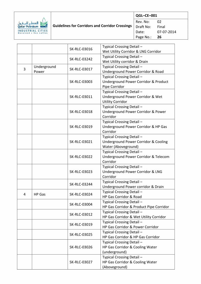
SK-RLC-03016 Typical Crossing Detail – Wet Utility Corridor & LNG Corridor
SK-RLC-03242 Typical Crossing Detail – Wet Utility corridor & Drain
3 Underground Power
SK-RLC-03017 Typical Crossing Detail – Underground Power Corridor & Road
SK-RLC-03003 Typical Crossing Detail – Underground Power Corridor & Product Pipe Corridor
SK-RLC-03011 Typical Crossing Detail – Underground Power Corridor & Wet Utility Corridor
SK-RLC-03018 Typical Crossing Detail – Underground Power Corridor & Power Corridor
SK-RLC-03019 Typical Crossing Detail – Underground Power Corridor & HP Gas Corridor
SK-RLC-03021 Typical Crossing Detail – Underground Power Corridor & Cooling Water (Aboveground)
SK-RLC-03022 Typical Crossing Detail – Underground Power Corridor & Telecom Corridor
SK-RLC-03023 Typical Crossing Detail – Underground Power Corridor & LNG Corridor
SK-RLC-03244 Typical Crossing Detail – Underground Power corridor & Drain
4 HP Gas SK-RLC-03024 Typical Crossing Detail – HP Gas Corridor & Road
SK-RLC-03004 Typical Crossing Detail – HP Gas Corridor & Product Pipe Corridor
SK-RLC-03012 Typical Crossing Detail – HP Gas Corridor & Wet Utility Corridor
SK-RLC-03019 Typical Crossing Detail – HP Gas Corridor & Power Corridor
SK-RLC-03025 Typical Crossing Detail – HP Gas Corridor & HP Gas Corridor
SK-RLC-03026 Typical Crossing Detail – HP Gas Corridor & Cooling Water (underground)
SK-RLC-03027 Typical Crossing Detail – HP Gas Corridor & Cooling Water (Aboveground)
Guidelines for Corridors and Corridor Crossings
QGL–CE–001
Rev. No: 02
Draft No: Final
Date: 07-07-2014
Page No.: 27
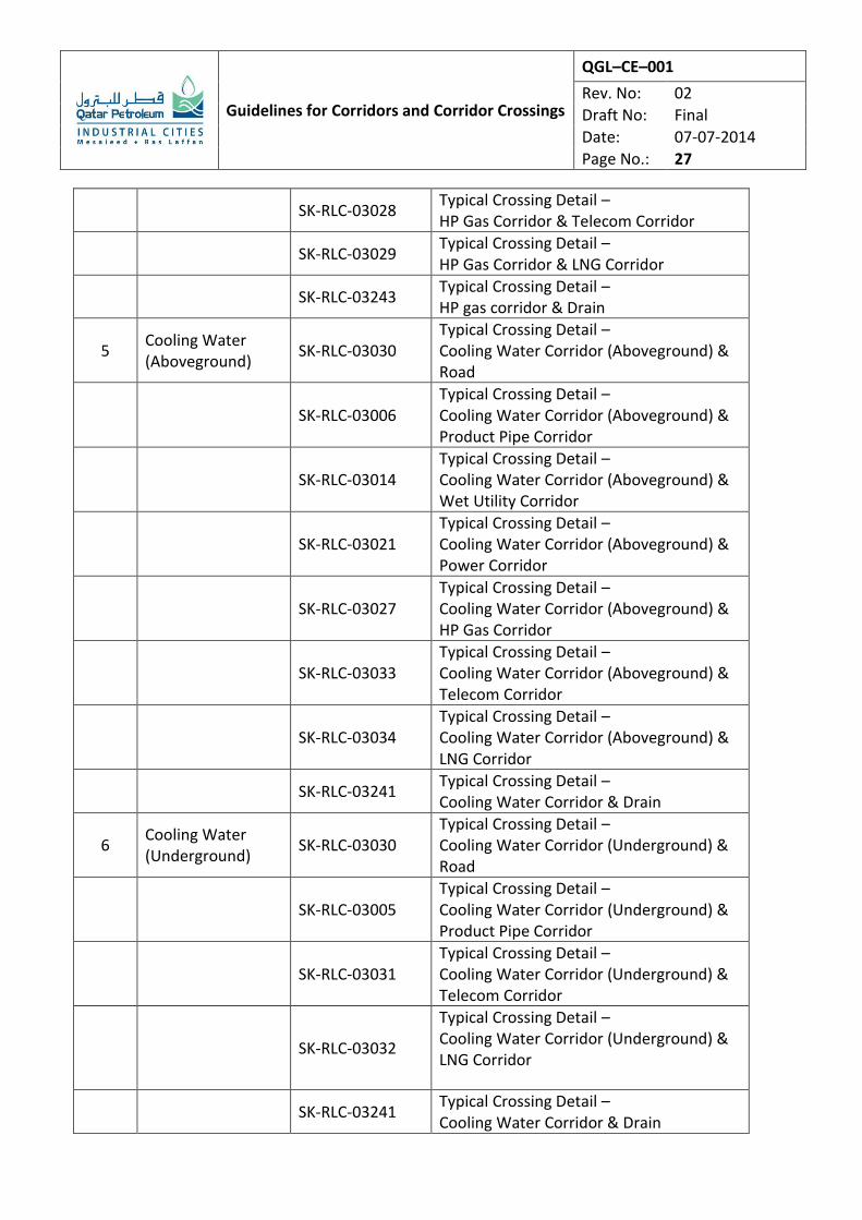
SK-RLC-03028 Typical Crossing Detail – HP Gas Corridor & Telecom Corridor
SK-RLC-03029 Typical Crossing Detail – HP Gas Corridor & LNG Corridor
SK-RLC-03243 Typical Crossing Detail – HP gas corridor & Drain
5 Cooling Water (Aboveground)
SK-RLC-03030 Typical Crossing Detail – Cooling Water Corridor (Aboveground) & Road
SK-RLC-03006 Typical Crossing Detail – Cooling Water Corridor (Aboveground) & Product Pipe Corridor
SK-RLC-03014 Typical Crossing Detail – Cooling Water Corridor (Aboveground) & Wet Utility Corridor
SK-RLC-03021 Typical Crossing Detail – Cooling Water Corridor (Aboveground) & Power Corridor
SK-RLC-03027 Typical Crossing Detail – Cooling Water Corridor (Aboveground) & HP Gas Corridor
SK-RLC-03033 Typical Crossing Detail – Cooling Water Corridor (Aboveground) & Telecom Corridor
SK-RLC-03034 Typical Crossing Detail – Cooling Water Corridor (Aboveground) & LNG Corridor
SK-RLC-03241 Typical Crossing Detail – Cooling Water Corridor & Drain
6 Cooling Water (Underground)
SK-RLC-03030 Typical Crossing Detail – Cooling Water Corridor (Underground) & Road
SK-RLC-03005 Typical Crossing Detail – Cooling Water Corridor (Underground) & Product Pipe Corridor
SK-RLC-03031 Typical Crossing Detail – Cooling Water Corridor (Underground) & Telecom Corridor
SK-RLC-03032
Typical Crossing Detail – Cooling Water Corridor (Underground) & LNG Corridor
SK-RLC-03241 Typical Crossing Detail – Cooling Water Corridor & Drain
Guidelines for Corridors and Corridor Crossings
QGL–CE–001
Rev. No: 02
Draft No: Final
Date: 07-07-2014
Page No.: 28
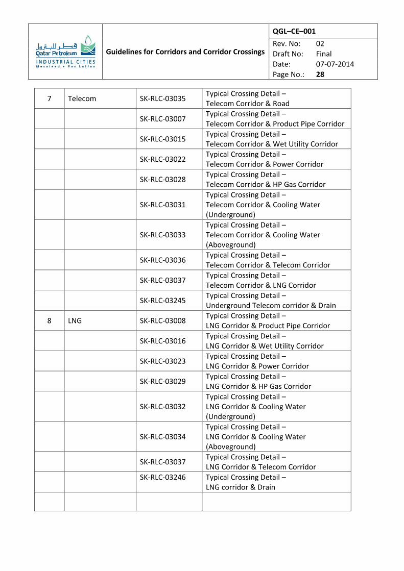
7 Telecom SK-RLC-03035 Typical Crossing Detail – Telecom Corridor & Road
SK-RLC-03007 Typical Crossing Detail – Telecom Corridor & Product Pipe Corridor
SK-RLC-03015 Typical Crossing Detail – Telecom Corridor & Wet Utility Corridor
SK-RLC-03022 Typical Crossing Detail – Telecom Corridor & Power Corridor
SK-RLC-03028 Typical Crossing Detail – Telecom Corridor & HP Gas Corridor
SK-RLC-03031 Typical Crossing Detail – Telecom Corridor & Cooling Water (Underground)
SK-RLC-03033 Typical Crossing Detail – Telecom Corridor & Cooling Water (Aboveground)
SK-RLC-03036 Typical Crossing Detail – Telecom Corridor & Telecom Corridor
SK-RLC-03037 Typical Crossing Detail – Telecom Corridor & LNG Corridor
SK-RLC-03245 Typical Crossing Detail – Underground Telecom corridor & Drain
8 LNG SK-RLC-03008 Typical Crossing Detail – LNG Corridor & Product Pipe Corridor
SK-RLC-03016 Typical Crossing Detail – LNG Corridor & Wet Utility Corridor
SK-RLC-03023 Typical Crossing Detail – LNG Corridor & Power Corridor
SK-RLC-03029 Typical Crossing Detail – LNG Corridor & HP Gas Corridor
SK-RLC-03032 Typical Crossing Detail – LNG Corridor & Cooling Water (Underground)
SK-RLC-03034 Typical Crossing Detail – LNG Corridor & Cooling Water (Aboveground)
SK-RLC-03037 Typical Crossing Detail – LNG Corridor & Telecom Corridor
SK-RLC-03246
Typical Crossing Detail – LNG corridor & Drain