Embed Size (px)
Citation preview
Guidelines for CEMS Performance Specificationsand Quality Assurance Requirementsfor Municipal Waste Combustion Facilities
September 1990
U.S. EPA Contract No. 68D90055Work Assignments 15 and 37
Prepared by:
James W. PeelerCEM/Engineering DivisionEntropy Environmentalists, Inc.Research Triangle Park, North Carolina 27709
Prepared for:
Nancy SeidmanNortheast States for Coordinated Air Use Management
By agreement with:
Emission Measurement BranchTechnical Support DivisionU.S. Environmental Protection AgencyResearch Triangle Park, North Carolina 27711
ACKNOWLEDGEMENTSThis guideline document is based on discussions of a workgroup
organized by the Northeast States for Coordinated Air UseManagement (NESCAUM). The workgroup was created to provideguidance to state and local agencies which use or plan to usecontinuous emission monitoring systems (CEMS) to determinecompliance at municipal waste combustion (MWC) facilities. Theguidelines are intended to promote consistency in designing andoperating CEMS and reporting monitoring data. The documentreflects the recommendations of state and federal agency staff. Inaddition, a draft of these guidelines was distributed to otheragencies, CEM equipment vendors, and MWC owners and operators.Their comments and suggestions were reviewed and discussed by theworkgroup and appropriate changes were made to the guidelines.
This project was funded by the NESCAUM states, the USEnvironmental Protection Agency Regional Offices in Boston, NewYork, and Philadelphia, the Stationary Source Compliance andTechnical Support Divisions of the US Environmental ProtectionAgency's Office of Air Quality Planning and Standards, and the USEnvironmental Protection Agency's Office of Research andDevelopment in the Atmospheric Research and Exposure AssessmentLaboratory. We thank all of the people who helped fund thisproject.
The workgroup was organized and managed by Nancy L. Seidman,Special Projects Director of NESCAUM. The workgroup members weredrawn from state and federal agencies. The members of theworkgroup are listed below.
California Air Resources Board - Robert Fletcher, PeterOuchida
Connecticut Bureau of Air Management - Carl Dodge, Mark Peak,Joe Ulevicus
Maine Bureau of Air Quality Control - Jane Longfellow, ScottMason
Massachusetts Division of Air Quality Control - Ed Braczyk,Robert Quevillon, William Sullivan
New Hampshire Air Resources Division - Andrew Bodnarik, JackGlenn
New Jersey Division of Environmental Quality - Ed Choromanski,Don Patterson
New York Division of Air Resources - Frank Buckman, RobertKerr, Tim Ross
NESCAUM - Nancy SeidmanOhio Division of Air Pollution Control - Tammy HilkensPennsylvania Bureau of Air Quality Control - Joe NazzaroVermont Air Pollution Control Division - Brian Fitzgerald
U.S. Environmental Protection AgencyRegion I, Boston - Tom Elter, Mary Ellen StantonRegion II, New York - Ann Zownir

Region II, Philadelphia - Robert VollaroOffice of Air Quality Planning and Standards, Stationary SourceCompliance Division - Louis PaleyOffice of Air Quality Planning and Standards, Technical SupportDivision - Terry Harrison, Gil WoodOffice of Research and Development, Atmospheric Research and theExposure Assessment Laboratory - Tom Logan
James W. Peeler and George W. Walsh of EntropyEnvironmentalists, Inc. participated in workgroup meetings, helpeddirect the efforts of the workgroup, and prepared this document.
We gratefully acknowledge the time invested by the workgroup.Their assistance and expertise made this project possible.
CONTENTS
PageSection 1 SUMMARY 1
Section 2 PERFORMANCE SPECIFICATIONS FOR SO2 AND NOx CEMS 7AT MUNICIPAL WASTE COMBUSTION FACILITIES
Section 3 PERFORMANCE SPECIFICATIONS FOR CO CEMS 15AT MUNICIPAL WASTE COMBUSTION FACILITIES
Section 4 PERFORMANCE SPECIFICATIONS FOR HCl CEMS 21AT MUNICIPAL WASTE COMBUSTION FACILITIES
Section 5 QUALITY ASSURANCE REQUIREMENTS FOR SO2, NOx, 25CO, AND HCl CEMS
Section 6 EQUIPMENT AND PERFORMANCE SPECIFICATIONS FOR 33OPACITY CEMS AT MUNICIPAL WASTE COMBUSTION FACILITIES
Section 7 QUALITY ASSURANCE REQUIREMENTS FOR OPACITY CEMS 37
Appendix Comparison of Accuracy Specifications
SECTION 1 -- SUMMARY
This guideline document is based on discussions of a workgrouporganized by the Northeast States for Coordinated Air UseManagement (NESCAUM). The workgroup was created to provideguidance to state and local agencies which use or plan to usecontinuous emission monitoring systems (CEMS) to determinecompliance at municipal waste combustion (MWC) facilities. Theguidelines are intended to promote consistency in designing andoperating CEMS and reporting monitoring data. The documentreflects the recommendations of state and federal agency staff. Inaddition, a draft of these guidelines was distributed to otheragencies, CEM equipment vendors, and MWC owners and operators.Their comments and suggestions were reviewed and discussed by theworkgroup and appropriate changes were made to the guidelines.
The NESCAUM recommendations reflect a consensus of theworkgroup participants arrived at through discussions duringseveral meetings. The resulting recommendations reflect thecollective experience, opinions, and judgement of the workgroupparticipants from the regulatory agency perspective. The scope ofthis project did not include the acquisition or analysis of data orother information to serve as the basis for specific requirementsor recommendations. The NESCAUM workgroup recommends that states adopt regulationswhich require the use of CEMS to determine compliance with emissionstandards on a continuous basis at MWC facilities. The regulationsshould:· Establish initial certification procedures and requirements forCEMS· Define quality assurance (QA) procedures and criteria for theongoing determination of the acceptability of the CEMS and themonitoring data· Specify minimum data capture requirements
The CEMS requirements in 40 CFR 60, including 60.13"Monitoring requirements", Appendix B - Performance Specifications,and Appendix F - Quality Assurance Procedures are recommended asa working base for state regulations. The federal requirements,however, are recognized as the minimum needed to ensure reliableCEMS performance and acceptable emissions data. The federalregulations have not been recently revised to keep up with theevolution of CEM technology. Recommendations are included here toaddress problems encountered in actual practice which are notadequately resolved by the existing federal regulations. Therecommendations are specifically designed for CEMS programs at MWCfacilities and they attempt to address technical issues that may beencountered in the implementation of monitoring programs subject toa wide variety of state regulations. It is hoped that theserecommendations will facilitate a more consistent approach in state
CEMS programs and requirements. State requirements for emission standards, percent removal
requirements, averaging times, and reporting may differsubstantially from the EPA New Source Performance Standardscurrently being developed. Significant differences among thevarious state regulations are also likely. Therefore, the NESCAUMworkgroup recommendations for performance specifications andquality assurance procedures are presented in general terms ratherthan in specific regulatory language. States desiring to adoptthese recommendations will need to make appropriate modificationsto them so that they are compatible with the applicable emissionstandards and other existing regulations. Specific language forrequirements based on the modified recommendations and thereferenced federal regulations will also need to be developed byeach state agency.
The following sections of this document present detailedrecommendations for performance specifications and qualityassurance requirements for gas and opacity CEMS. Many of thespecifications are expressed in terms of "percent of span" sincethe actual measurement range of the instrumentation should bespecified by the state agency to be compatible with the applicableregulations and enforcement policies. In specifying the spanvalue, the agency should consider trade-offs between an expandedmeasurement range and more accurate data at typical emission levelsor at the level of the emission standard. Some factors to considerin specifying the span value include: the applicable emissionstandard or percent removal requirement, the averaging time for thestandard, the inherent variability of uncontrolled and controlledemissions during normal operation and during malfunctions of thefacility, and the actions to be taken by the agency and the sourceowner or operator if emissions exceed the measurement range of theCEMS.
The recommendations presented in this document were developedfor MWC facilities. Many of these recommendations could also beapplied to other sources; however, no attempt was made in thisproject to identify or address the specific technical andregulatory issues associated with CEMS programs at other sourcecategories. These issues include:· procedures used to convert gas concentration measurements tounits of the standard,· emissions variability associated with the process and controlequipment and the corresponding averaging time for CEMS datarecording and reporting and determining compliance with applicablestandards,· likelihood of substances within the effluent stream causinganalytical interferences with either CEMS measurements or referencemeasurements used for relative accuracy determinations· effluent conditions such as temperature, pressure, moisturecontent, and the presence of other materials within the effluentstream that may affect the operation and reliability of
instrumentation.Careful consideration of these and other issues is warranted inapplying the recommendations presented here to other sourcecategories.
The recommended performance specifications provide the basisfor determining the initial acceptability of the CEMS and thequality assurance requirements provide a basis for determining theongoing acceptability of data and monitoring equipment. Thequality assurance recommendations include criteria for decidingthat a monitoring system is "out-of-control" and state that datacollected during such periods cannot be used to satisfy minimumdata capture (i.e., data availability) requirements. A minimumdata availability requirement has been included in the qualityassurance recommendations. It is recognized that some states mayrequire higher levels of CEMS availability, or define CEMSavailability in other terms.
The additional requirements associated with the workgrouprecommendations will increase the costs of CEMS performance testsand quality assurance activities. However, for many sources theadditional cost will be relatively small since effective CEMprograms which can meet the recommended requirements have alreadybeen developed and implemented. It is hoped that the guidelineswill help avoid costly misunderstandings between the source and theagency which can result in the purchase or installation ofunacceptable equipment. The incremental costs attributable to theNESCAUM workgroup recommendations are believed to be a relativelysmall fraction of the total costs for MWC facilities.
1. Summary of Performance Specification Recommendations for GasCEMS
NESCAUM workgroup recommendations for performancespecifications for SO2 and NOx CEMS, CO CEMS, and HCl CEMS arepresented in Section 2 through 4 of this document, respectively.The recommendations reference the federal regulations. Majordifferences include:a. Calibration gases are required to be used for daily calibrationchecks, performance tests and periodic audits of all CEMS.Calibration of the entire measurement system is required.Procedures are included to allow source owners or operators todemonstrate alternate procedures and alternate methods forcalibration checks and audits. These requirements are designed toeliminate use of calibration procedures that check only a portionof the measurement system and procedures that have not beenevaluated and documented by the user.b. The values of calibration gases used for drift tests and dailycalibration checks must be determined quantitatively. Severalprocedures are provided to establish the values of the gases.These requirements are necessary to assess the accuracy of themonitoring data on a daily basis.c. A four-point linearity test must be performed for gas monitors.
This can be done with the two gases used for the daily checks andtwo Protocol 1 gases used for quarterly audits. (A three-pointcheck is required for HCl monitors.) This requirement is necessaryto eliminate the use of non-linear monitoring systems which may beadjusted to provide the correct response at zero and upscalecalibration check points but do not necessarily provide accuratedata at other concentrations.d. An additional minimum accuracy specification e.g., meandifference not to exceed 5 ppm, or equivalent (10 ppm for COmonitors) is added to prevent the accuracy specifications frombeing overly restrictive for those applications where emissionlevels are very low. The relative accuracy test procedures arealso clarified to eliminate some of problems that are encounteredin conducting these tests at MWC facilities.e. A cycle time/response time specification and test procedure isadded for all monitors. The specification for SO2 , NOx, diluent,and HCl monitors is 15 minutes which is consistent with the EPArequirements in 40 CFR 60.13. A one-minute cycle time/responsetime specification is included for CO monitors since some stateswill require reporting of one-minute values for this pollutant.2. Summary of Quality Assurance Recommendations for Gas CEMS
NESCAUM workgroup recommendations for quality assurancerequirements for all gas CEMS are presented in Section 5 of thisdocument. The recommendations reference the federal regulations.Major differences include:a. Submission of a preliminary monitoring plan to the agency isrequired in most cases. The plan should set forth the basicapproach that will be used to comply with the monitoringrequirements. It is hoped that agency review of the plan will helpresolve misunderstandings, unacceptable approaches, and confusionabout the monitoring requirements before costly mistakes occur.b. A CEMS quality assurance plan should be developed for eachfacility. Detailed guidance is provided with respect to the QAplan content.c. An annual review of the QA plan and results of itsimplementation is required to be performed by the source owner oroperator. The results of this review and changes to the QA planare reported to the agency.d. Routine zero and upscale calibration checks of the monitoringsystem must be performed on a daily basis. This requirement isequivalent to the daily calibration check in 40 CFR 60.13 exceptthat the procedures recommended here are similar to those describedfor the performance specification test.e. A cylinder gas audit consisting of the four-point linearitytest described in the performance specification recommendationsshould be performed each calendar quarter. Only routinecalibration adjustments according to the written procedures in theQA plan are permitted before the audit.f. A relative accuracy test should be performed in one calendarquarter immediately before or after the cylinder gas audit. The
CEMS must pass both tests for performance to be consideredacceptable.g. A minimum data availability specification of 90 percent ofsource operating hours is included. The time required for zero andupscale calibration checks, cylinder gas audits, and certain QAactivities included in approved plans is not subtracted from CEMSavailability. 3. Summary of Performance Specification Recommendations forOpacity CEMS
NESCAUM workgroup recommendations for performancespecifications for opacity CEMS are presented in Section 6 of thisdocument. The recommendations reference the federal regulations.Major differences include:a. All opacity monitors must provide external calibration filteraccess to facilitate performance audits.b. All opacity monitors must provide access to instantaneous orone-minute opacity measurements in addition to six-minute averages.c. Calibration error tests must be performed in the field or aperformance audit must be conducted to demonstrate that testresults from the manufacturer are representative of performance ofthe installed monitor.4. Summary of Quality Assurance Recommendations for Opacity CEMS
NESCAUM workgroup recommendations for quality assurancerequirements for opacity CEMS are presented in Section 7 of thisdocument. The recommendations are similar to the requirements forgas CEMS except:a. A opacity monitor performance audit is conducted instead of thecylinder gas audit that is required for gas monitors.b. A zero alignment procedure is performed for opacity monitorsinstead of the relative accuracy test that is required for gasCEMS.
SECTION 2PERFORMANCE SPECIFICATIONS FOR SO2 AND NOx CEMSAT MUNICIPAL WASTE COMBUSTION FACILITIES
This section describes the NESCAUM workgroup recommendationsfor monitor location requirements, equipment and performancespecifications, and corresponding test procedures for SO2 and NOxCEMS installed at MWC facilities. Specifically, the NESCAUMworkgroup recommends that states consider adopting the EPArequirements contained in "PERFORMANCE SPECIFICATION 2 -SPECIFICATION AND TEST PROCEDURES FOR SO2 AND NOx CONTINUOUSEMISSION MONITORING SYSTEMS IN STATIONARY SOURCES" of 40 CFR 60,Appendix B revised as of July 1, 1988, with the changes detailed inItems 1 through 8 below. When emission standards necessitate useof a diluent monitor (O2 or CO2) to determine emissions in units ofthe standard, NESCAUM recommends that states consider adopting theEPA requirements contained in "PERFORMANCE SPECIFICATION 3 -SPECIFICATIONS AND TEST PROCEDURES FOR O2 AND CO2 CONTINUOUSEMISSION MONITORING SYSTEMS IN STATIONARY SOURCES" of 40 CFR 60,Appendix B revised as of July 1, 1988, with the changes detailedbelow.
1. Use of Calibration GasesA design specification should be added to require that SO2,
NOx and diluent monitors be able to accept calibration gases fordaily calibration checks, performance specification tests, andperiodic quality assurance audits. Furthermore, the designspecification should require that the calibration gas injectionpoint be in the sample probe or at the probe outlet so that theentire measurement system is checked when calibration gases areintroduced to the monitoring system. For measurement systemsemploying dilution probes or similar devices, the calibration gasesmust be introduced prior to the dilution point and in such a mannerthat they are diluted to the same extent as the sample gases fromthe effluent stream. Similarly, for sample acquisition systemsusing aspirators or eductors, the calibration gases must beintroduced prior to these devices even if these components are partof the sample probe assembly.
Source owners or operators (or instrument vendors) maydemonstrate that alternate daily calibration check procedures ordevices provide results comparable to those obtained by usingcalibration gases to check the entire measurement system. Forexample, a source owner or operator may elect to demonstrate thevalidity of an alternate calibration check procedure for (1)in-situ monitors that accept calibration gases and which also usecalibration gas cells, or (2) for extractive monitors where dailycalibration checks of the entire system are unnecessarilyburdensome. In such cases, a demonstration can be accomplished byconducting concurrent calibration drift tests using both the
specified method and the alternate method during the performancespecification test. If the results indicate acceptable monitorperformance with respect to the applicable drift specifications,the alternate procedure may be used for the daily zero and upscalechecks of the monitor. However, the quality assurance plan mustinclude (1) a detailed discussion of all assumptions associatedwith the alternate procedure, and (2) mandatory procedures forconducting periodic comparisons of the specified and alternatecalibration methods. Such comparisons should be performed on amonthly or more frequent basis until the alternate procedure hasbeen evaluated and documented to the satisfaction of the agency.
Source owners or operators may request approval of alternateroutine calibration check procedures for monitors that cannotaccept calibration gases and alternate procedures for conductingthe linearity and response time tests for these monitors. Sourceowners or operators are cautioned that alternate calibrationprocedures need to be evaluated carefully and thoroughly and thata single relative accuracy test at one operating condition does notprovide a sufficient evaluation of the validity of a particularcalibration procedure. The source owner or operator should submita written plan to the agency for conducting such a demonstration.If the plan is approved, the source owner or operator may carry outthe demonstration program and submit a detailed report describingthe alternate procedure, all assumptions associated with thealternate procedure, the procedures and conditions of thedemonstration, the results of the tests conducted, and appropriaterevisions to the CEMS quality assurance plan, as applicable. Thevalidity of any alternate procedure would be re-examined duringquarterly accuracy audits.
2. Data Availability and Back-Up Data Recording DevicesAll CEMS must operate continuously without repairs,
unscheduled maintenance, or non-routine adjustments during theperformance specification tests to determine calibration drift,linearity, and relative accuracy. In addition, minimum dataavailability specifications are included as QA requirements and areapplicable to the operation of the CEMS after completion of theperformance specification tests. (See Section 5, Quality AssuranceRequirements for SO2, NOx, CO, and HCL CEMS, 8. Minimum DataAvailability Requirements of this document.)
Most CEMS at MWC facilities will include a computer dataacquisition system that performs various operations including (1)recording effluent concentration measurements, (2) recording dailycalibration check results, (3) compensation of effluentmeasurements for drift, (4) calculation of emissions in units ofthe standard, (5) averaging of measurement data, (6) generatingexcess emission reports, and (7) interfacing with telecommunicationsystems where required by the agency. Data acquisition systems areinherently monitor- and source-specific and may need to accommodatediverse reporting requirements of various states, therefore much
flexibility in the design of these systems is needed. When thedata acquisition system is inoperative, many vital CEMS functionsare suspended and data availability is immediately affected.Source owners and operators are encouraged, but not required, toinclude a back-up recording device or other appropriate redundancywithin the data acquisition system to maximize data availability.Where such devices are used, conformance with the calibration driftand linearity specifications should be determined based on resultsobtained from both the primary data acquisition system and theback-up recording devices in order to avoid additional testing whenthe back-up recording device is placed in service. However,failure of a performance specification based on data from a back-uprecording device should not necessitate retesting.
3. Calibration Drift Test and Reference ValuesThe calibration drift specifications for SO2 and NOx monitors
(2.5 percent of span) and O2 and CO2 monitors (0.5 percent O2 orCO2) as well as the calibration drift test procedures inPerformance Specifications 2 and 3 should be maintained except that(1) the calibration drift tests must be performed using calibrationgases or other prior approved alternate calibration procedure, and(2) the concentration value of the calibration gases must be known.The values of the calibration gases may be established through theuse of certified reference materials (CRMS), standard referencematerials (SRMS), or EPA Protocol 1 gases. Alternatively,calibration gas values determined by the gas manufacturer'scertified analysis (i.e., + 2 % of tag value) may be used if theconcentration is checked by direct comparison with Protocol 1gases, or by triplicate analysis using an appropriate EPA testmethod or an equivalent procedure. The direct comparison of tagvalues and Protocol 1 gases can be accomplished using the installedCEMS in most cases.
Comparison with Protocol 1 gases may be accomplished byintroducing both the subject gas, a zero concentration gas and atleast two Protocol 1 gases into an analyzer demonstrated previouslyto meet the linearity test specification in Item 4, below.(Ambient air and two Protocol 1 gases may be used for O2 monitorswhich cannot analyze zero gas.) The Protocol 1 gases shouldsatisfy the audit range specifications of Appendix F, Procedure 1;however, alternate ranges including at least two Protocol 1 gaseswhich bracket the concentration value of the subject gas may alsobe used, subject to the approval of the agency. The analyzerresponses to all of the Protocol 1 calibration gases shall be usedto construct a calibration curve for the analyzer. The analyzerresponse to the subject gas and the calibration curve shall be usedto determine the concentration of the subject gas. If thedifference between the measured concentration and the tag value ofthe subject gas is less than 3 percent of the tag value, use thetag value as the actual concentration. If the difference betweenthe measured concentration and the tag value is greater than 3
percent of the tag value, repeat all gas injections and check allcalculations. If the difference still exceeds 3=percent of the tagvalue, use the measured concentration as the actual concentration.(See 40 CFR 60, Appendix A, Method 6C, "6.1.2 Alternative Number 2"for specific requirements for the analysis of SO2 calibration gasesby EPA test methods. Similar procedures may be used for theanalysis of NO and diluent calibration gases. See Method 7E ,Section 6.1 for analysis criteria for NO calibration gases.)
Calibration drift tests are intended to identify problems thataffect the stability of the monitor calibration; however, suchtests are conducted over a short period and therefore cannotrepresent the full range of operating conditions for the CEMS.Experience has shown that many of the problems resulting inexcessive calibration drift and loss of monitoring data are relatedto poorly conditioned electrical power, inadequate or unsuitablecompressed air supply, excessive vibration, ambient temperaturechanges, ambient dust loading, and other site-specific applicationproblems. Source owners and operators are strongly encouraged toidentify these and other problems that may affect CEMS performanceand take appropriate actions to minimize the loss of CEMS data dueto these problems.
4. Linearity TestA new performance specification and test procedure should be
added to require a four-point cylinder gas audit to demonstrate thelinearity of each pollutant and diluent monitoring channel. Thelinearity specification and test procedure applies to the entiremonitoring channel, including the data acquisition system, asinstalled and operated at the MWC facility. (A non-linear analyzerused in conjunction with appropriate adjustments by the dataacquisition system is acceptable.) Source owners and operators areencouraged, but not required, to have equipment vendors demonstrateconformance with the linearity specification prior to shipment ofthe CEMS to the subject facility. However, the linearity test isrequired to be conducted for each CEMS after installation.
The linearity test should use the zero and upscalecalibration values used for the daily calibration checks and thetwo audit points specified for cylinder gas audits by Appendix F,Procedure 1. If the high range audit point (i.e., 50 to 60 percentof the pollutant monitor span) of Procedure 1 is used for the dailyupscale checks, an audit gas of 80 to 90 percent of span should besubstituted for the high range audit point. Protocol 1 gases, CRMSor SRMS should be used for the two audit points that supplement thedaily calibration checks. Three non-consecutive measurementsshould be made for each of the calibration gases (e.g., zero, low,mid, high, zero, low, mid, high, etc.)
The linearity specification should require that the meandifference between the calibration gas value and the monitorresponses at each of the four points be calculated from the threemeasurements. The mean difference at all four test points must be
less than 5 percent of span for SO2 and NOx monitors and 0.5percent O2 or CO2 for diluent monitors.
The linearity test should be performed as soon as practicalbefore or after the relative accuracy test. Only the routinecalibration drift adjustments are allowed between the two tests.Other adjustments or repairs to the monitoring system wouldnecessitate repeating the linearity and the accuracy test. (Duringsubsequent quarterly audits, only calibration drift adjustmentsaccording to the written procedure contained in an approved QA planare allowed prior to the linearity test or the relative accuracytest.)
5. Relative Accuracy TestThe workgroup recommends that states maintain the performance
specification test procedures for the relative accuracy test inPerformance Specification 2 with the clarifications describedbelow. The daily calibration checks should be performed on eachday that the relative accuracy testing is performed and that noadjustments or repairs to the monitoring system other than theroutine calibration drift adjustments may be conducted. Thedistinction between routine adjustments and corrective action fora malfunctioning CEMS is particularly difficult for the initialrelative accuracy test since there is little or no track record onwhich to base decisions and since the QA plan is usuallyincomplete. The following approach is recommended to resolve thisissue. Prior to conducting the test, the source operator mustestablish (1) the criteria for adjustment of the monitorcalibration, (2) the criteria or schedule for the performance ofroutine maintenance activities, and (3) the frequency or criteriafor conducting additional calibration checks. This informationshould be made available to the agency observer. The dailycalibration checks should be performed following the normalprocedure before initiating the test and adjustments should only bemade as indicated by the applicable criteria. During the test, thesource may check the calibration at reasonable intervals and abortthe test if unscheduled maintenance or adjustment are necessary.If corrective action other than routine adjustments are required,a 24-hour period should elapse to verify that the CEMS drift iswithin acceptable limits before a new test is begun. The new testmay begin immediately, subject to the approval of the agency, if itcan be shown that the corrective action or adjustment does notaffect the calibration drift of the CEMS. Performance Specifications 2 and 3 require only that therelative accuracy test be performed for the entire measurementsystem (i.e., pollutant and diluent monitor) in units of theapplicable standard. However, the source owner or operator isstrongly encouraged, but not required, to determine also therelative accuracy for each monitoring channel in units ofconcentration in order to obtain a more complete evaluation ofmonitor performance.

Problems in conducting the relative accuracy tests may beencountered where significant fluctuations in the emission levelsor very low emission levels are encountered. Therefore, bothrelative accuracy specifications in Performance Specification 2(i.e., relative accuracy less than 20 percent of the mean referencevalue or less than 10 percent of the standard) should be retained.Also, an additional specification should be added to provide anabsolute minimum accuracy specification of 5 ppm mean differencefor SO2 or NOx CEMS relative to the test method. (See Appendix Afor a technical discussion of the various accuracy specifications.)Thus, for a concentration standard corrected to 7 percent O2 thefollowing accuracy specifications should apply; relative accuracyless than 20 percent of the mean reference value, relative accuracyless than 10 percent of the standard, or mean difference less than5 ppm corrected to 7 percent O2, whichever is least restrictive.For cases where the emission standard is expressed in units oflb/MM=Btu, an equivalent absolute accuracy specification may becalculated using an average or typical diluent concentration. Forexample, it can be shown that 5 ppm SO2 at 7 percent O2 isapproximately equivalent to 0.01 lb/MM=Btu using the F-Factors andconversion values in EPA Method 19.
For sources subject to an SO2 or NOx percent removal standardthat is more restrictive than the emission standard (or where thereis no absolute emission standard) an implicit emission standardshould be determined as:Implicit Standard = [1-Percent Removal/100] x Avg. UncontrolledEmissionsThe implicit emission standard should be used to calculate therelative accuracy result as "10 percent of the standard." For thisdetermination, the uncontrolled emissions may be obtained byaveraging all of the reference test data from the relative accuracytest of the CEMS at the inlet to the control device.
The relative accuracy test procedures should be clarified toexplicitly prohibit modification of the operation of time-sharedCEMS during the test to increase the sampling frequency, tominimize the frequency of sample system cleaning (blow-back)operations or, to reduce the number of locations from which CEMSsamples are obtained. In order to minimize the effects offluctuating emission levels, the source owner or operator maychoose (1) to extend the sampling time to at least 1 hour forintegrated sampling methods, or (2) to increase the number ofsamples that are obtained during a run for grab sampling methods.Alternate relative accuracy test procedures for time-shared CEMSthat reduce the number of locations for which reference samples areobtained may be approved by the agency on a case-by-case basis.
The source owner or operator may use EPA Method 6 orinstrumental Method 6C for SO2 concentration measurements forrelative accuracy tests. Methods 7, 7A, 7C, or 7D or instrumentalMethod 7E may be used for NOx concentration measurements, andMethod 3 or=instrumental Method 3A may be used for O2 or CO2
concentration concentration measurements for relative accuracytests. NOTE: Methods 7C and 7D may be subject to analyticalinterferences when used at MWC sources; the applicability of thesemethods has not been established by field testing at this time.
6. Alternate Accuracy Test ProcedureSection 10. Alternative Procedures of Performance
Specification 2 contains procedures for conducting a cylinder gasaudit in place of a relative accuracy test when a waiver of therelative accuracy test requirement is granted under the conditionsspecified in 60.13 (j). According to these regulations, a sourceowner or operator may petition the Administrator for a waiver ofthe relative accuracy test requirement when the CEMS is not thecompliance method and when the emissions are less than 50=percentof the standard as determined by a source performance test. Theregulations specify the content of the petition, the conditionswhen it may be applied for, and the conditions under which thewaiver may be rescinded.
The Performance Specification 2 cylinder gas audit proceduresare not needed because the same audit test points are alreadyincluded as part of the more elaborate linearity test that isrecommended for all CEMS installed at MWC facilities. (See Item 4above.) As with any requirement, the agency may waive the relativeaccuracy test requirement in cases where the emission levels arevery low as indicated by the results of source performance tests orother independent effluent measurements regardless of whether theCEMS are used as the compliance method. However, no generalguidance or criteria is provided here for waiving the relativeaccuracy test requirement.
7. Cycle Time and Response Time TestA specification should be added that requires all SO2, NOx,
and diluent CEMS to complete at least one cycle of operation(sampling, analyzing, and data recording) for each successive15-minute period, (i.e., a minimum of four samples per hour).Extractive monitoring systems may be time-shared between twomeasurement locations; however, the cycle time requirement must bemet for both measurement locations. (Some states have adoptedregulations or policies prohibiting any time-sharing of monitors atMWC facilities, and some states will allow time-sharing only as anemergency backup provision.)
Source owners and operators are encouraged to installmonitoring systems fully capable of representing emissions from thefacility. The agency should not excuse apparent excess emissionsthat may be due to nonrepresentative sampling because of long CEMScycle times or minimum CEMS sampling frequencies. In addition,sources required to install and operate NOx control equipment maybe subject to shorter measurement cycle time specifications in thefuture.
A response time test should be added to determine if eachmonitoring channel of the CEMS complies with the cycletime/sampling frequency specification. The average upscale anddownscale response times should be determined from threerepetitions of each test. The greater of the average upscale oraverage downscale response times should be reported as the responsetime for the system.
The upscale response time should be determined by injectingzero gas into the measurement system and then recording the amountof time required for the system to return to the effluentconcentration after the zero gas injection has been stopped.Similarly, the downscale response time should be determined byinjecting a high range calibration gas and then recording theamount of time required for the monitoring system to return to theeffluent concentration after the gas injection is stopped.Specifically, the response time may be measured as the timerequired for the monitor to complete 95 percent of theconcentration step-change occurring after the gas injection isstopped during each test. For monitoring systems that perform aseries of operations, (purge-blow back, sample, analyze, etc.) theinjection of calibration gases should be timed to produce thelongest response time.
In many cases, the actual response time of the measurementsystem is only a few seconds as compared to several minutes toperform the necessary cycle of operations. In these cases, it isoften possible to establish conformance with the cycle timerequirement by inspection of the system rather than by injection ofcalibration gases. Such determinations are subject to the approvalof the agency.
8. Data Reporting Equipment SpecificationsAdditional equipment or design specifications may be added by
states to facilitate the specific record keeping and reportingrequirements that may apply. Various state agencies are currentlyconsidering a wide range of alternatives including: automated datareporting using magnetic media, telecommunication systems thatallow agency representatives to obtain or review data on-demandfrom remote locations, and real-time or intermittent telemetrysystems for CEM data and information. No additional guidance isincluded because of the diversity of state requirements andapproaches.
SECTION 3PERFORMANCE SPECIFICATIONS FOR CARBON MONOXIDE CEMSAT MUNICIPAL WASTE COMBUSTION FACILITIES
This section describes the NESCAUM workgroup recommendationsfor monitor location requirements, equipment and performancespecifications, and corresponding test procedures for CO CEMSinstalled at MWC facilities. Specifically, the NESCAUM workgrouprecommends that states consider adopting the EPA requirementscontained in "PERFORMANCE SPECIFICATION 4 - SPECIFICATION AND TESTPROCEDURES FOR CARBON MONOXIDE CONTINUOUS EMISSION MONITORINGSYSTEMS IN STATIONARY SOURCES" of 40 CFR 60, Appendix B revised asof July 1, 1988, the Federal Register Vol. 53, No. 204, October21,1988, and the changes detailed in Items 1 through 8 below.
Many of the changes that are recommended for CO monitors arethe same as those recommended for SO2 and NOx CEMS. For thepurposes of these discussions it is assumed that the CO monitor isused to measure emission levels in units of concentration (ppm).Where a diluent monitor is used to adjust the data to a consistentbasis (e.g., 7 percent O2 or 12 percent CO2) or where data is to bereported in terms of combustion efficiency, appropriate adjustmentsto the recommended requirements should be made. It is assumed thatthe upper limit of the CO measurement range (span value) would beapproximately 300 to 500 ppm. Greater measurement ranges may beneeded for facilities using refuse-derived-fuels particularlyduring start-up. Alternate measurement ranges may be used subjectto the approval of the agency when emission levels are consistentlymuch lower than the standard.
1. Use of Calibration GasesA design specification should be added to require that CO
monitors be able to accept calibration gases for daily calibrationchecks, performance specification tests, and periodic qualityassurance audits. In addition, the recommendations regarding wherethe gases are introduced to the measurement system, the applicationto dilution sampling systems, and the requirements fordemonstrating the adequacy of alternate calibration techniques arethe same as described in Section 2 for SO2 CEMS.
Special considerations may apply to CO monitors which utilizea correction procedure to eliminate the influence of CO2. It maybe necessary to use CO calibration gases with a specificconcentration of CO2 to assess monitor performance. Additionalmonitor-specific procedures would be needed to verify the accuracyof the correction procedure. These procedures should be evaluatedand approved by the agency on a case-by-case basis.
2. Data Availability and Back-Up Data Recording DevicesAll CEMS must operate continuously without repairs,
unscheduled maintenance, or non-routine adjustments during the
performance specification tests to determine calibration drift,linearity, and relative accuracy. In addition, minimum dataavailability specifications are included as QA requirements and areapplicable to the operation of the CEMS after completion of theperformance specification tests. (See Section 5, Quality AssuranceRequirements for SO2, NOx, CO, and HCL CEMS, 8. Minimum DataAvailability Requirements.)
Recommendations and suggestions regarding the use andperformance testing of back-up recording devices for CO CEMS arethe same as described in Section 2 for SO2 CEMS.
3. Calibration Drift Test and Reference ValuesIn many cases, the daily upscale calibration check value
required by Performance Specification 4 (i.e., 50 to 90 percent ofspan) is very much greater than both the normal CO operating leveland the level of the emission standard. Calibration checks atthese levels may not represent actual performance of the monitor.The requirement should be revised to allow the use of an upscalecalibration check value that either (a) approximates the COconcentration equivalent to the applicable emission limit, or (b)is within 50 to 90 percent of the span value. Other upscalecalibration check values may be used subject to the approval of theagency. Source operators may elect to conduct additional checks ofthe CO monitor calibration to evaluate the monitoring data fortheir own uses.
The calibration drift specification for CO monitors inPerformance Specification 4 (drift not to exceed 5 percent of spanfor 6 out of 7 test days) should be changed to restrict drift to3 percent of span for 7 consecutive days. The more restrictivelimit is consistent with the capabilities of contemporaryinstrumentation. Also, the expression of the limit not to beexceeded for 7 consecutive days is necessary for the implementationof Appendix F, Procedure 1 control limits.
The drift test procedures in Performance Specification 4should be maintained except that (1) the calibration drift testsmust be performed using calibration gases or other prior approvedalternate calibration procedure, and (2) the concentration value ofthe calibration gases must be known. The specifications andprocedures that may be used for establishing the values of thecalibration gases are the same as described in Section 2 for SO2CEMS. The suggestion that the source owner or operator identifyapplication problems that may affect the stability of the CO CEMSis also the same as for SO2 CEMS.
4. Linearity TestA new performance specification and test procedure should be
added to require a four-point cylinder gas audit to demonstrate thelinearity of CO monitors. The linearity specification and testprocedures apply to the entire monitoring channel, including thedata acquisition system, as installed and operated at the MWC
facility. (A non-linear analyzer used in conjunction withappropriate adjustments by the data acquisition system isacceptable.) Source owners and operators are encouraged, but notrequired, to have equipment vendors demonstrate conformance withthe linearity specification prior to shipment of the CEMS to thefacility. However, the linearity test is required to be conductedfor each CEMS after installation.
The requirements for the selection of the audit points forthe linearity test and the test procedures for CO monitors are thesame as described in Section 2 for SO2 CEMS. The linearityspecification should require that the mean difference between thecalibration gas value and the monitor responses at each of the fourpoints be calculated from the three measurements. The meandifference at all four test points must be less than 5 percent ofspan for CO monitors.
The linearity test should be performed as soon as practicalbefore or after the relative accuracy test. Only the routinecalibration drift adjustments are allowed between the two tests.Other adjustments or repairs to the monitoring system wouldnecessitate repeating the linearity and the accuracy test. (Duringsubsequent quarterly audits, only calibration drift adjustmentsaccording to the written procedure contained in an approved QA planare allowed prior to the linearity test or the relative accuracytest.)
5. Relative Accuracy TestThe recommended procedures and conditions for the relative
accuracy test are the same as those described above for SO2 CEMS.In addition, the workgroup recommends that both of the relativeaccuracy specifications in Performance Specification 4 (i.e.,relative accuracy less than 10 percent of the mean reference valueor less than 5 percent of the standard) be retained. Also, anadditional specification should be added to provide an absoluteminimum accuracy specification of 10 ppm mean difference for COCEMS relative to the reference test method. Thus, for aconcentration standard the following accuracy specifications shouldapply: relative accuracy less than 10=percent of the meanreference value, relative accuracy less than 5 percent of thestandard, or mean difference less than 10 ppm, whichever is leastrestrictive. Where necessary, the 10 ppm mean difference limit maybe converted to an equivalent limit expressed in units of theapplicable standard using the average diluent concentrationmeasured during the relative accuracy test and applicableconversion factors.
The relative accuracy test should be performed using Method10. When the installed CEMS uses a nondispersive infrared (NDIR)analyzer, Method 10 shall use the alternative interference trapspecified in section 10.1 of the method. Method 10B is anacceptable alternative to Method 10. The following alternatives
may be approved by the agency in specific cases.
Alternative 1 - The test may be conducted using Method 10 withoutthe interference trap if a laboratory interference test isperformed for the analyzer prior to the field test. The laboratoryinterference test should include the analysis of SO2, NO, and CO2calibration gases representing the range of expected effluentconcentrations. Acceptable performance is indicated if the COanalyzer response to each of the gases is less than 1 percent ofthe applicable measurement range of the analyzer.
Alternative 2 - The test may be conducted using Method 10 withoutan interference trap, and without a CO2 trap, subject to theapproval of the agency, based on the submission of informationdemonstrating the absence of CO2 interference for the testanalyzer. (If this option is chosen, any interferences that arepresent will cause the test analyzer to be biased high. There isalso a possibility that the installed monitor would be subject tothe same interference which would not be detected during therelative accuracy test. The potential for the high bias may beacceptable to the agency provided that the source owner or operatoraccepts the potential bias and cannot later challenge the accuracyof the data.)
6. Alternate Accuracy Test ProcedureAs described in Section 2 for SO2 CEMS, the alternate accuracy
test procedure for CO monitor are not needed since the moreelaborate linearity test is required for all CO monitors installedat MWC facilities. The agency may waive the relative accuracy testrequirement if the emissions are consistently very low (e.g., lessthan 20 ppm) based on source performance test results (i.e.,"compliance tests") or other independent effluent measurements.The agency should be cautious in waiving the relative accuracy testrequirement based solely on CEMS data since some analyzers havebeen found to respond poorly to low concentrations of CO.
7. Cycle Time and Response Time TestFor sources subject to an emission limit with a one-hour or
shorter averaging period, an additional specification should beincluded that requires the CO CEMS to complete at least one cycleof operation (sampling, analyzing, and data recording) for each successive one-minute period, (i.e.,60 samples per hour) with an allowance of 10=minutes per hour forcleaning and calibration operations. For sources subject tolimits with longer averaging periods, alternate cycle timespecifications may be established by the agency. A response timetest should be added to determine if the CO monitor meets the cycletime/sampling frequency specification. The response time testshould be conducted according to the procedures described above for
SO2 CEMS.CO monitors with response times exceeding the applicable cycle
time specification are acceptable if the longer response time isdue to delay or "lag" time attributable to the sample acquisitionequipment. For these monitors, performance is acceptable if thetime between the analyzer's initial response and the responseequivalent to 95 percent of the actual concentration change is lessthan the cycle time specification (regardless of the delay betweenthe analyzer's initial response and the time that the gas injectionis stopped during the response time test) provided that the totalresponse time does not exceed 15 minutes.
8. Data Reporting Equipment SpecificationsAdditional equipment or design specifications may be added by
states to facilitate the specific record keeping and reportingrequirements that may apply. Various state agencies are currentlyconsidering a wide range of alternatives including: automated datareporting using magnetic media, telecommunication systems thatallow agency representatives to obtain or review data on-demandfrom remote locations, and real-time or intermittent telemetrysystems for CEM data and information. No additional guidance isincluded because of the diversity of state requirements andapproaches.
SECTION 4PERFORMANCE SPECIFICATIONS FOR HCl CEMSAT MUNICIPAL WASTE COMBUSTION FACILITIES
Some states may require that HCl CEMS be used to monitoremissions and/or determine HCl control efficiency at MWCfacilities. The NESCAUM workgroup did not address nor attempt todetermine whether HCl CEMS should be installed at MWC facilities.It is noted that the EPA has not adopted performance specificationsfor HCl monitors in Part 60 and has not announced plans to requireHCl monitors at MWC facilities or any other sources regulated underthe New Source Performance Standards. Nevertheless, the NESCAUMworkgroup recommends appropriate monitor location requirements,equipment and performance specifications, and corresponding testprocedures for HCl CEMS installed at MWC facilities. This sectiondescribes the NESCAUM workgroup recommendations for HCl CEMSperformance specifications based on currently availableinformation. Changes to these specifications may be appropriate asadditional information and operational experience with HCl CEMS isobtained.
For the purposes of these discussions it is assumed thatPerformance Specification 2 would serve as a basic model for HClrequirements. Also, many of the changes that are recommended abovefor SO2 and NOx CEMS are also appropriate for HCl CEMS. It isassumed that HCl monitors would be used to measure emission levelsin units of concentration (ppm). Where a diluent monitor is usedto adjust the data to a consistent basis (e.g., lb/MM=Btu, 7percent O2, or 12 percent CO2) appropriate adjustments to therecommended requirements should be made. It is assumed that theHCl measurement range for controlled emissions would beapproximately 250 ppm and that the measurement range foruncontrolled emissions would be approximately 1500=ppm.
1. Use of Calibration GasesA design specification should be added to require that HCL
monitors be able to accept calibration gases for daily calibrationchecks, performance specification tests, and periodic qualityassurance audits. In addition, the recommendations regarding wherethe gases are introduced to the measurement system, the applicationto dilution sampling systems, and the requirements fordemonstrating the adequacy of alternate calibration techniques arethe same as described above for SO2 CEMS. Because of the highercost for HCl calibration gases and the amount of gas used by someof the currently available monitors, it is expected that ademonstration of an alternate calibration technique would beattempted for most HCL CEMS applications.
2. Data Availability and Back-Up Data Recording Devices
All CEMS must operate continuously without repairs,unscheduled maintenance, or non-routine adjustments during theperformance specification tests to determine calibration drift,linearity, and relative accuracy. In addition, minimum dataavailability specifications are included as QA requirements and areapplicable to the operation of the CEMS after completion of theperformance specification tests. (See Section 5, Quality AssuranceRequirements for SO2, NOx, CO, and HCL CEMS, 8. Minimum DataAvailability Requirements of this document.)
Recommendations and suggestions regarding the use andperformance testing of back-up recording devices for HCl CEMS arethe same as described in Section 2 for SO2 CEMS.
3. Calibration Drift Test and Reference ValuesA calibration drift specification for HCl monitors restricting
drift to 5 percent of span for 7 consecutive days should beestablished. The drift test procedures in PerformanceSpecification 2 should be used except that (1) the calibrationdrift tests must be performed using calibration gases or otherprior approved alternate calibration procedure, and (2) the valueof the calibration gases must be obtained from the vendorscertified analysis (within three months of the performance test) orby performing triplicate analysis of the gases using proposed EPAMethod 26. The suggestion that the source owner or operatoridentify application problems that may affect the stability of themonitor is also the same as for SO2 CEMS.
4. Linearity TestA performance specification and test procedure should be added
to require a three-point cylinder gas audit to demonstrate thelinearity of each HCl monitor. The linearity specification andtest procedure apply to the entire monitoring channel, includingthe data acquisition system, as installed and operated at theparticular facility. (A non-linear analyzer used in conjunctionwith appropriate adjustments by the data acquisition system isacceptable.) This test should use the zero and upscale calibrationgas used for the daily calibration checks and an additional auditpoint at 20 to 30 percent of span. The recommended procedures forperforming the test are the same as described above for SO2 CEMSexcept that Protocol 1 gases are not available for HCl. Therefore,the concentration value of all three calibration gases should bedetermined as described above in Item 3. The linearityspecification should require that the mean difference between thecalibration gas value and the monitor responses at each of thethree points be calculated from the three measurements. The meandifference at all three test points must be less than 5 percent ofspan for HCl monitors.
5. Relative Accuracy TestThe recommended procedures and conditions for the relative
accuracy test are the same as those described above for SO2 CEMS.The following accuracy specifications are also recommended:relative accuracy less than 20 percent of the mean reference value,relative accuracy less than 10 percent of the standard, or meandifference less than 5 ppm, whichever is least restrictive. Forcases where the emission standard is expressed in units of lb/MMBtu or corrected to a specified O2 or CO2 concentration, anabsolute accuracy specification equivalent to 5 ppm should becalculated using an average or typical diluent concentration andapplicable conversion factors. The appropriate procedures for usein cases where a percent removal standard is more restrictive thanthe emission standard are the same as for SO2 CEMS. The relativeaccuracy test should be performed using proposed EPA Method=26. 6. Alternate Accuracy Test Procedure
The same considerations apply to the alternate accuracy testprocedure for HCl monitors as were described above for SO2 CEMS.In essence, the alternate accuracy test procedure is not neededsince the more elaborate linearity test is required for all HClCEMS installed at MWC facilities. The agency may decide to waivethe relative accuracy test requirement if the emissions areconsistently very low as indicated by source performance testresults (i.e., "compliance tests") or other independent effluentmeasurements. However, the relative accuracy test should not bewaived based on low concentrations indicated by the HCl CEMSbecause of the possibility of significant or total loss of HCl inthe effluent samples within the sample acquisition/sampleconditioning equipment.
7. Cycle Time and Response Time TestA specification should be included that requires all HCl CEMS
to complete at least one cycle of operation (sampling, analyzing,and data recording) for each successive 15-minute period, (i.e., aminimum of four samples per hour). The same considerations applyto time-sharing of HCl monitors as are described above for SO2CEMS. A response time test should be conducted according to theprocedures described above for SO2 CEMS.
8. Data Reporting Equipment SpecificationsAdditional equipment or design specifications may be added by
states to facilitate the specific record keeping and reportingrequirements that may apply. Various state agencies are currentlyconsidering a wide range of alternatives including: automated datareporting using magnetic media, telecommunication systems thatallow agency representatives to obtain or review data on-demandfrom remote locations, and real-time or intermittent telemetrysystems for CEM data and information. No additional guidance isincluded because of the diversity of state requirements andapproaches.
SECTION 5QUALITY ASSURANCE REQUIREMENTS FORSO2, NOx, CO, HCl CEMS
This section describes the NESCAUM workgroup recommendationsfor quality assurance requirements applicable to SO2, NOx, CO, andHCl CEMS installed at MWC facilities. The NESCAUM workgrouprecommendations are similar to and adopt specific parts of 40 CFR60, APPENDIX F, PROCEDURE 1. QUALITY ASSURANCE REQUIREMENTS FOR GASCONTINUOUS MONITORING SYSTEMS USED FOR COMPLIANCE DETERMINATIONrevised July 1, 1988. The QA requirements that are adopted mustalso be consistent with the applicable performance specificationsand test procedures. Therefore, the specific NESCAUM workgrouprecommendations for QA requirements and procedures described inItems 1 through 8 below reference the corresponding performancespecification recommendations in Sections 2, 3, and 4 of thisdocument.
The following definition is used:Quality assurance consists of the activities and procedures thatare performed by the source owner or operator to ensure that CEMdata meet certain criteria with respect to accuracy, precision,availability, and representativeness after the successfulcompletion of the initial performance specification test.Specific QA requirements for gas CEMS installed at MWC facilitiesfor the measurement of SO2, NOx, CO, and HCl emission levels andpercent removal are presented in Items 1 through 7 below.1. Preliminary Monitoring Plan
Each source owner or operator required to install a CEMS forthe measurement of one or more gaseous pollutants or diluentconcentrations should submit a preliminary monitoring plan to theagency prior to the installation of the monitoring equipment. Thepreliminary monitoring plan need not be submitted if a draft CEMSQA plan is submitted to the agency prior to the installation of themonitoring equipment.
Submission of the preliminary monitoring plan is required toprovide an opportunity for identification of misunderstandingsbetween the agency and the source owners or operators with respectto the applicable CEMS requirements and acceptable monitoringapproaches during the planning phase of the monitoring program. Itis hoped that the submission of such a plan and review by theagency will (1) resolve problems attributable to ambiguousregulations, (2) minimize the likelihood of the purchase andinstallation of unacceptable monitoring equipment, and (3) avoidthe need for development of a detailed quality assurance planbefore actual operating experience with the monitoring equipment isobtained.
The preliminary monitoring plan should very briefly set forth
the basic approach that will be used to comply with the applicableCEMS requirements. It should include:a. The identification, location, and description of the specificcombustor unit(s) (e.g., plant name, unit number, unit size orcapacity, general type of control system, etc.)b. Identification of the applicable regulations and continuousmonitoring requirements (e.g., EPA NSPS, state regulations, permitrequirements, etc.)c. Identification of the type of monitor (e.g., extractive, pointin-situ, etc.) the CEMS manufacturer or vendor, and the modelnumber or other identifying feature of the equipment to beinstalledd. Identification of the analytical technique for each analyzerthat will be used (e.g., NDIR, UV absorption, chemiluminescence,etc.)e. Identification and description of the proposed monitoringlocation(s) (i.e., position along the effluent path) andidentification of the specific measurement point(s) at eachmonitoring location from which samples will be obtainedf. Discussion of plans for time-sharing of extractive monitoringsystems between two or more monitoring locations either as apermanent installation or as a back-up provision when a particularmonitor is inoperativeg. Identification of the procedures that will be used to convertmeasurement data to units of the standard, including specificconversion factors, assumptions, and equations as applicableh. Description of any mathematical procedures that will be usedto correct emission measurement data for calibration drift,interference of other constituents, quenching, or other measurementphenomena applicable to the proposed measurement systemi. Brief description of the data acquisition system and datarecording devicesj. Identification of any exceptions to the performancespecifications or other applicable monitoring requirements and anyalternate procedures that may require the approval of the agency
2. CEMS Quality Assurance PlanEach source owner or operator should develop a CEMS quality
assurance plan for each facility. The quality assurance planshould be submitted to the agency no later than 90=days aftercompleting the initial successful performance specification test ofthe CEMS. At a minimum the quality assurance plan must address thefollowing specified quality control and quality assessmentsubjects:a. Background information. - - This should include:· Identification and description of the specific combustor unit(s)· Identification of the applicable regulations and monitoringrequirements· Identification and description of the monitoring instrumentation· Description of the measurement location(s) and sampling points
· Description of the data recording devices and data handlingsystemThis information is a reiteration and update of informationcontained in the preliminary monitoring plan and information thatis usually included in the performance specification testreport(s). It is included to assure that both the user and theagency are aware of changes to the original plan and the currentstatus of the monitoring program at the facility.b. Procedures used to establish proper calibration of the CEMS. -- These procedures should explain how the monitoring equipment isadjusted to provide the correct responses both initially and afterrepairs or corrective action. The procedures should address thecalibration of both the components and the overall measurementsystem. The procedures should also identify assumed parameters(i.e., conversion factors, effluent moisture content, etc.) thatare important to the fundamental calibration of the monitoringequipment. Procedures for verifying the validity of mathematicalprocedures used to correct or adjust the monitoring data shouldalso be included.c. Procedures used for the routine (daily) zero and upscalecalibration checks and criteria for adjustment of the CEMS forexcessive drift. - - For monitoring systems that use calibrationgases for the daily checks, these procedures should describe: · Where the gases are introduced to the measurement system · How the correct flow rate and pressure for the gas injectionsare determined and maintained· The length of time the gases are injected· The data display device(s) used to determine the monitorresponse· Any procedures necessary for the interpretation of the data
· The criteria for deciding if adjustments to the monitoringsystem are necessary· The action to be taken when adjustments are neededThese procedures should include specification of the supplier andtype of calibration materials used for the daily calibration checksand the method used to establish the concentration values of thesematerials.
For monitoring systems that use an alternate method forperforming the routine zero and upscale checks, similar informationdescribing the procedures is required. The specific requirementsshould be addressed in the written plan submitted when applying forapproval of the alternate procedure during the performancespecification test [See also "Item 1. Use of Calibration Gases" inthe recommended performance specifications.]d. Procedures used for cylinder gas audits (linearity tests) andrelative accuracy tests. - - These procedures should detail howthe accuracy assessments are conducted at the specific facility.The values of the two Protocol 1 calibration gases used for thelinearity test, the supplier, and the steps taken to ensure that
the certification is current should be described. The specificprocedures for introducing the gases to the monitoring system asdescribed in Item 2. c (above) for the daily checks should also beincluded. For relative accuracy tests, the test methods to beused, sampling location/sampling points, duration of sampling runs,procedures for converting the reference data to units of thestandard, and CEMS data interpretation/calculation proceduresshould be specified.e. Quality control procedures including daily and periodic checksof system or component performance, preventive maintenanceprocedures, spare parts inventory, etc. - - These types ofprocedures are inherently monitor- and source-specific. However,detailed written procedures and corresponding data forms have beenfound to be effective for identifying developing problems andpromoting consistency and thoroughness in performing daily andperiodic checks of CEMS. Minimum preventive maintenance proceduresare usually specified by the monitor manufacturer and should beincluded in the quality assurance plan. The spare parts thatshould be available on site depends on the data availabilityrequirements, delivery time from suppliers or other sources, andthe likelihood of failure of individual components; historicalperformance is the best indicator of the parts that may be needed.The quality control procedures should explain the organization ofQA responsibilities among the various departments/groups orindividuals at the facility.f. Corrective action procedures for repair, adjustment, orreplacement of the CEMS or its components. - - Corrective actionprocedures are often trouble-shooting efforts and are thereforedifficult to describe in sufficient detail to be useful. However,clear objective criteria for determining when corrective action isneeded based on the results of the required daily checks andperiodic accuracy tests should be included. Additional criteriarelated to procedures or checks included as quality controlprocedures may also be helpful in resolving developing problems.This section should also include alternative monitoring proceduresfor use when minimum data availability requirements cannot be metby the CEMS.g. Procedures used for data reduction, record keeping, andreporting of CEMS information. - - These procedures should detailexactly how the CEMS data is handled including:· methods for correcting data for calibration drift· specific averaging procedures· methods of excluding invalid data and calibration data fromemission averages· equations, constants, and assumptions used to convertconcentration measurements to units of the standard· provisions for recording process/control system data and reasonsfor excess emissions· provisions for recording CEMS downtime, adjustments, and repairs· procedures for review and editing of data
The media, format, and location of all records and all reports tobe submitted to the agency should be specified. The individuals orgroups responsible for maintenance of records, development ofreports, and review of reports should be identified.
3. Quality Assurance Plan RevisionEach source owner or operator should review the QA plan and
all data generated by its implementation at least once each yearand revise or update the plan, as necessary, based on the resultsof the annual review. The revised plan must be available foron-site review by the agency at any time. Within thirty days ofcompletion of the annual QA plan review, the source owner oroperator must submit a written explanation of all changes (or lackof changes) to the agency.
The agency may request revision of the QA plan at any timebased on the results of emission report reviews, inspections,audits, review of the QA plan, or any other information availableto the agency.
4. Routine Zero and Upscale Calibration ChecksEach source owner or operator should perform a zero (or
low-level value between 0=and 20 percent of span) and upscale (50to 90 percent of span) calibration drift check at least once dailyin accordance with a written procedure contained in the CEMS QAplan. The daily check procedure must provide a check of the entiremeasurement system including sample acquisition equipment, samplelines, conditioning systems, analyzers, and data recording devices.The procedure must be accomplished by introducing calibration gasesof the required concentrations in the sampling probe or at thesampling probe outlet. For measurement systems employing dilutionprobes or similar devices, the calibration gases must be introducedprior to the dilution point and in such a manner that they arediluted to the same extent as the sample gases from the effluentstream. Similarly, for sample acquisition systems using aspiratorsor eductors, the calibration gases must be introduced prior tothese devices even if these components are part of the sample probeassembly. The values of the calibration gases may be establishedthrough the use of certified reference materials (CRMS), standardreference materials (SRMS), or EPA Protocol 1 gases.Alternatively, calibration gas values determined by the gasmanufacturer's certified analysis (i.e., + 2 % of tag value) maybe used if the concentration is checked by direct comparison withProtocol 1 gases, or by triplicate analysis using an appropriateEPA test method or an equivalent procedure. (See recommendedPerformance Specifications for SO2 CEMS, Item 3 for specificprocedures for establishing the gas concentrations.)
Source owners or operators may conduct a demonstration of analternate calibration check procedure subject to the approval ofthe agency. This demonstration may be conducted during the initialperformance specification test or at a later time. (See Section 2,
Performance Specifications for SO2 and NOx CEMS6, "Item 1. Use ofCalibration Gases" for guidance on demonstration of an alternatemethod.)
The monitoring system must allow the amount of positive andnegative drift (difference between the analyzer response andcorrect value of the calibration gas) to be quantified. At aminimum, the monitoring system shall be adjusted when the driftexceeds two times the performance specification limit. (Therecommended calibration drift performance specifications are 2.5percent of span for SO2 and NOx monitors, 0.5=percent O2 or CO2 fordiluent monitors, 3 percent of span for CO monitors, and 5=percentof span for HCl monitors.) When adjustments are made, the driftcheck should be repeated after the adjustments are completed toverify that the monitor responds correctly.
The data acquisition system software in some monitoringsystems automatically applies a mathematical correction to the CEMSemissions data based on the routine zero and span check results.Some other CEMS utilize an automatic control system for calibrationdrift adjustments. Manual adjustment of systems using automaticadjustments is not required until the drift based on the unadjustedresponses is equivalent to 10 percent of span for the monitoringchannel. These systems must allow determination of (1) the amountof drift in the unadjusted values, (2) the magnitude of thecorrection factor or adjustment that is applied, and (3) theadjusted system response to the daily zero and upscale calibrationvalues.
5. Cylinder Gas AuditA cylinder gas audit (linearity test) should be performed each
calendar quarter using the same procedures and gas specificationsthat were used during the initial performance specification test.The audit should use the two audit points specified by Appendix F,Procedure 1 in conjunction with the zero and upscale calibrationpoints used for the daily checks. If the high range audit point(i.e., 50 to 60 percent of the pollutant monitor span) of Procedure1 is used for the daily upscale checks, an audit gas of 80 to 90percent of span should be substituted for the high range auditpoint. A three-point audit check is required for HCl monitors.The same specification used in the performance specification testshould also apply for the quarterly audits. Acceptable performanceis indicated if the mean difference between the monitor responsesand the value of the calibration gas is less than 5 percent of spanat each of the four audit points for SO2, NOx, CO, and HClmonitors. The acceptance criteria for diluent monitors is 0.5percent O2 or CO2. If the system fails the cylinder gas audit,take corrective action and repeat the audit until successful. Theresults of the cylinder gas audit should be reported to the agencywith the emissions report for the period during which the audit isconducted.
6. Relative Accuracy TestsA relative accuracy test (minimum of nine sampling runs)
should be performed at least once per year using the sameprocedures and specifications used in the initial performancespecification test. The relative accuracy test should be conductedas soon as practical before or after one of the quarterly cylindergas audits to demonstrate the validity of the gas calibrationtechnique and verify assumptions about the calibration procedure.No adjustments or repairs to the monitoring system other than theroutine calibration drift adjustment according to the writtenprocedure contained in the QA plan can occur between the cylindergas audit and the relative accuracy test. To be considered workingproperly, the CEMS must satisfy both the relative accuracy andcylinder gas audit specifications. If the system fails to meeteither specification, take corrective action and repeat both testsuntil successful. The results of the relative accuracy test shouldbe reported to the agency with the emissions report for the periodduring which the test is conducted.
7. Out-of-Control PeriodsCriteria for "out-of-control" periods are similar to those
defined in Appendix F, Procedure 1. Specifically, the monitor isout-of-control if (a) the calibration drift exceeds two times theperformance specification drift limit for five consecutive days,(b)=the calibration drift exceeds five times the performancespecification limit on any day, (c) the system fails a relativeaccuracy test, or (d) the monitor fails a cylinder gas auditdescribed above in Item 5. Data collected during out-of-controlperiods cannot be used to satisfy minimum data availabilityrequirements.
8. Minimum Data Availability RequirementsSource owners and operators subject to continuous monitoring
requirements should properly operate and maintain all monitoringequipment at all times that the source is operational. For sourceswhere gas CEMS are required for the measurement of controlled oruncontrolled emissions of SO2, NOx, CO, or HCl, continuousmonitoring data in units of the standard should be available for aminimum of 90 percent of the source operating hours for eachreporting period (e.g., quarterly). For the purpose of determiningconformance with this requirement, the time required to performroutine (e.g., daily) zero and upscale calibration checks, andquarterly linearity tests is included as CEM operating time. Thetime required for scheduled or unscheduled CEMS maintenance orother quality assurance activities is not included as operatingtime in the determination of CEMS availability except as may bespecifically allowed in a QA plan approved by the agency. Somestates may require higher levels of CEMS data availability or mayrequire the use of redundant monitoring devices for all or somemonitoring parameters.

In the event that the installed CEMS can not achieve theminimum data availability requirement, the source owner or operatorshould use alternate monitoring procedures (e.g., back-up monitors,parameter monitoring, performance testing, etc.) subject to theapproval of the agency. The alternate monitoring procedures arerequired to be described in the QA plan. (See Section 5, 2 QualityAssurance Plan Item f.)
SECTION 6EQUIPMENT AND PERFORMANCE SPECIFICATIONS FOR OPACITY CEMSAT MUNICIPAL WASTE COMBUSTION FACILITIES
This section describes the NESCAUM workgroup recommendationsfor monitor location requirements, design specifications,performance specifications, and corresponding test procedures foropacity CEMS installed at MWC facilities. Specifically, theNESCAUM workgroup recommends that states consider adopting the EPArequirements contained in "PERFORMANCE SPECIFICATION 1 -SPECIFICATION AND TEST PROCEDURES FOR OPACITY CONTINUOUS EMISSIONMONITORING SYSTEMS IN STATIONARY SOURCES" of 40 CFR 60, Appendix Brevised July 1, 1988, with the changes detailed in Items 1 through5 below.
1. Performance Specification 1 Design SpecificationsThe design specifications in Performance Specification 1
should be adopted for: peak and mean spectral response, angle ofview, angle of projection, optical alignment sight, simulated zeroand upscale calibration checks, access to external optics, andautomatic zero compensation indicator. In addition, "Section 6.Design Specification Verification Procedure" of PerformanceSpecification 1 should be used to determine conformance with theabove design requirements. The optional requirement in PerformanceSpecification 1, "Section=5.1.9 External Calibration Filter Access"should be changed to a mandatory requirement to ensure thecapability of auditing the monitor using external calibrationattenuators.
(Note: The EPA Atmospheric Research and Exposure AssessmentLaboratory, Quality Assurance Division has initiated an evaluationof the procedures used for the manufacturer's certification ofconformance with the design specifications for opacity monitors.Revision of Performance Specification 1 requirements or testprocedures may also result from this effort. Among others, futurerevisions may include (1) test procedure clarifications, (2)specifications for uniformity of light beam, (3) specificprocedures for checking the photopic response.)
2. Cycle Time and Measurement FrequencyAn additional design specification should be added to require
that all opacity monitors complete a minimum of one cycle ofsampling and analyzing for each successive 10-second period and onecycle of data recording for each successive 6-minute period orother period as specified in applicable regulations during normaloperation. This requirement is similar to the requirement in 40 CFR 60.13 (e ) (1) and is also consistent withthe response time specification in Performance Specification 1. The
specification should require that the opacity monitoring systemhave the capability to display measurements for 1-minute periods orshorter intervals to facilitate monitor performance evaluations.
3. Data Availability and Back-Up Data Recording DevicesAll opacity CEMS must operate continuously without repairs,
unscheduled maintenance, or non-routine adjustments during theperformance specification tests. In addition, minimum dataavailability specifications are included as a quality assurancerequirements and are applicable to the operation of the CEMS aftercompletion of the performance specification tests. (See Section 7,Quality Assurance Requirements for Opacity CEMS, 8. Minimum DataAvailability Requirements.)
It is recognized that most MWC CEMS will include a computerdata acquisition system and that when the data acquisition systemis inoperative, many vital CEMS functions are suspended and dataavailability is immediately affected. Source owners and operatorsare encouraged, but not required, to include a back-up recordingdevice or other appropriate redundancy within the data acquisitionsystem in order to maximize data availability.
4. Performance Specification 1 Performance Test Procedures andAcceptance Criteria
The Performance Specification 1 criteria should be adopted forcalibration error, response time, conditioning period, operationaltest period, and zero and calibration drift. In addition, Section7,. Performance Specification Verification Procedure should be usedto determine conformance with these criteria. However, therequirement that allows the calibration error test to be performedeither at the manufacturer's facility or in the field should bechanged. The regulation should allow the source owner or operatorto choose either (1) to conduct the calibration error tests in thefield, or (2) to conduct a performance audit of the monitor duringthe operational test period to ensure that calibration error testresults obtained at the manufacturer's facility are representativeof installed CEMS performance. Procedures for conducting aperformance audit are included with the opacity monitor qualityassurance requirements.
5. Data Reporting Equipment SpecificationsAdditional equipment or design specifications may be added by
states to facilitate the specific record keeping and reportingrequirements that may apply. Various state agencies are currentlyconsidering a wide range of alternatives including: automated data reporting using magneticmedia, telecommunication systems that allow agency representativesto obtain or review data on-demand from remote locations, andreal-time or intermittent telemetry systems for CEM data andinformation. No additional guidance is included because of thediversity of state requirements and approaches.
SECTION 7QUALITY ASSURANCE REQUIREMENTSOPACITY CEMS
This section describes the NESCAUM workgroup recommendationsfor QA requirements applicable to opacity CEMS installed at MWCfacilities. The QA requirements that are adopted should beconsistent with the applicable performance specifications and testprocedures. Therefore, the specific NESCAUM workgrouprecommendations for QA requirements and procedures described inItems 1 through 7 below reference the performance specificationrecommendations in Section 6 of this document.
The following definition is used:Quality assurance consists of the activities and procedures thatare performed by the source owner or operator to ensure that CEMdata meet certain criteria with respect to accuracy, precision,availability, and representativeness after the successfulcompletion of the initial performance specification test.
The following QA requirements are recommended for opacity CEMS:1. Preliminary Monitoring Plan
Each source owner or operator required to install an opacityCEMS should submit a preliminary monitoring plan to the agencyprior to the installation of the monitoring equipment. Thepreliminary monitoring plan need not be submitted if a draft CEMSquality assurance plan is submitted to the agency prior to theinstallation of the monitoring equipment.
Submission of the preliminary monitoring plan is required toprovide an opportunity for identification of misunderstandingsbetween the agency and the source owners or operators with respectto the applicable CEMS requirements and acceptable monitoringapproaches during the planning phase of the monitoring program. Itis hoped that the submission of such a plan and review by theagency will (1) resolve problems attributable to ambiguousregulations, (2) minimize the likelihood of the purchase andinstallation of unacceptable monitoring equipment, and (3) avoidthe need for development of a detailed quality assurance planbefore actual operating experience with the monitoring equipment isobtained.
The plan should very briefly set forth the basic approach thatwill be used to comply with the applicable monitoring requirements.It should include:a. The identification, location, and description of the specificcombustor unit(s) (e.g., plant name, unit number, unit size orcapacity, general type of control system, etc.)
b. Identification of the applicable regulations and continuousmonitoring requirements (e.g., EPA NSPS, state regulations, permitrequirements, etc.)c. Identification of the CEMS manufacturer or vendor, the modelnumber or other identifying feature of the equipment to beinstalledd. Identification of the proposed monitoring location(s) (i.e.,position along the effluent path), description of thetransmissometer measurement path orientation at each monitoringlocation, measurement path length, and stack exit diametere. Discussion of procedures and equipment that will be used tocalculate the opacity of emissions discharged to the atmospherewhere two or more transmissometers are installed in multiple ductsfor a single unit or where emissions from multiple units areexhausted through a common stackf. Description of any automatic procedures that will be used tocorrect or adjust opacity measurement results for calibration driftg. Description of the data recording devices that will be usedh. Identification of any exceptions to the performancespecifications or other applicable monitoring requirements and anyalternate procedures that may require the approval of the agency
2. CEMS Quality Assurance PlanEach source owner or operator should develop a CEMS QA plan
for each facility. The QA plan should be submitted to the agencynot later than 90=days after completing the initial successfulperformance specification test of the CEMS. At a minimum the QAplan must address the following quality control and qualityassessment subjects:a. Background information. - - This should include:· Identification and description of the specific combustor unit(s)· Identification of the applicable regulations and monitoringrequirements· Identification and description of the monitoring instrumentation· Description of the measurement location(s) and monitor paths· Description of the data recording devices and data handlingsystem. This information is a reiteration and update of informationcontained in the preliminary monitoring plan and information thatis usually included in the performance specification testreport(s). It is included to assure that both the user and theagency are aware of changes to the original plan and the currentstatus of the monitoring program at the facility.b. Procedures used to establish proper calibration of the CEMS.- - These procedures should explain how the monitoring equipment isadjusted to provide the correct responses both initially and afterrepairs or corrective action. The procedures should address thecalibration of the transmissometer(s), the data recording devices,and the overall measurement system. Procedures for verifying thevalidity of mathematical corrections or other automatic adjustments
to the monitoring data should be included.c. Procedures used for the routine (daily) zero and upscalecalibration checks and criteria for adjustment of the CEMS forexcessive drift. - - These procedures should explain:· How the daily calibration checks are initiated · The data display device(s) used to determine the monitorresponses,· The criteria for deciding if adjustments to the monitoringsystem are necessary· The action to be taken when adjustments are needed
It is particularly important that any assumptions associatedwith the calibration check procedure be understood and that anyauxiliary monitor parameters necessary to assess monitorperformance be identified.d. Procedures for performance audits and zero alignment checks.- - These procedures should provide any special informationnecessary for the conduct of performance audits or theinterpretation of the audit results. Zero alignment proceduresshould explain how the monitor is removed from the stack and set upunder clear path conditions or how the test is performed on theinstalled monitor during source outages. The specific proceduresused to adjust the simulated zero device and the records of thezero alignment results and adjustments should be explained.e. Quality control procedures including daily and periodic checksof system or component performance, preventive maintenanceprocedures, spare parts inventory, etc. - - These procedures areinherently monitor- and source-specific. However, detailed writtenprocedures and corresponding data forms have been found to beeffective for identifying developing problems and promotingconsistency and thoroughness in performing daily and periodicchecks of monitoring systems. Minimum preventive maintenanceprocedures are usually specified by the monitor manufacturer andshould be included in the quality assurance plan. The spare partsthat should be available on site depends on the data availabilityrequirements, delivery time from suppliers or other sources, andthe likelihood of failure of individual components; historicalperformance is the best indicator of the parts that may be needed.The quality control procedures should explain the organization ofQA responsibilities among the various departments/groups orindividuals at the facility.f. Corrective action procedures for repair, adjustment, orreplacement of the CEMS or its components. - - Corrective actionprocedures are often trouble-shooting efforts and are thereforedifficult to describe in sufficient detail to be useful. However,clear objective criteria for determining when corrective action isneeded based on the results of the required daily checks andperiodic audits should be included.
g. Procedures used for data reduction, record keeping, andreporting of CEMS information. - - These procedures should detail
exactly how the CEMS data is handled including:· methods for correcting data for calibration drift, if applicable· criteria for identifying invalid data · provisions for recording process/control system data and reasonsfor excess emissions; · provisions for recording and tracking CEMS downtime adjustmentsand repairs.
The media, format, and location of all records and all reportsto be submitted to the agency should be specified. The individualsor groups responsible for maintenance of records, development ofreports, and review of reports should be identified.
3. Quality Assurance Plan RevisionEach source owner or operator should review the QA plan and
all data generated by its implementation at least once each yearand revise or update the plan, as necessary, based on the resultsof the annual review. The revised plan must be available foron-site review by the agency at any time. Within thirty days ofcompletion of the annual QA plan review, the source owner oroperator must submit a written explanation of all changes (or lackof changes) to the agency.
The agency may request revision of the QA plan at any timebased on the results of emission report reviews, inspections,audits, review of the QA plan, or any other information availableto the agency.
4. Routine Zero and Upscale Calibration ChecksEach source owner or operator should perform a zero (or
low-level value between 0=and 20 percent of span) and upscale (50to 90 percent of span) calibration drift check at least once dailyin accordance with a written procedure contained in the CEMS QAplan. (This requirement is the same as that contained in 40 CFR60.13 (d)=(1).) The daily check procedure must provide a systemcheck of the analyzer internal optical surfaces and all electroniccircuitry including the lamp and photodetector assembly.
The monitoring system must allow the amount of positive andnegative drift (difference between the analyzer response andcorrect value of the calibration check devices) to be quantified.At a minimum, the monitoring system shall be adjusted when thedrift exceeds the performance specification limit, i.e., 2 percentopacity. (This criteria is twice as restrictive as the criteria in40 CFR 60.13.) The transmissometer optical surfaces exposed to theeffluent should be cleaned prior to performing the zero andcalibration drift adjustments except for systems using automaticzero adjustments. When calibration adjustments are made, the driftcheck should be repeated after the adjustments are completed toverify that the monitor responds correctly.
Some opacity monitors use an automatic zero compensationdevice to offset dust accumulation on the optical surfaces or otherchanges in the electro-optical components. Also, the data
acquisition system software in some monitoring systemsautomatically applies a mathematical correction to the monitoringdata based on the zero and upscale calibration check results.Manual adjustment of systems using automatic adjustments should beperformed when the drift based on the unadjusted responses (or themagnitude of the adjustment) is equivalent to 4 percent opacity.These systems must allow determination of the amount of drift inthe unadjusted values or the magnitude of the correctionfactor/adjustment that is applied.
5. Performance AuditA performance audit of each opacity CEMS should be performed
each calendar quarter according to the procedures contained in"Performance Audit Procedures for Opacity Monitors"EPA-600/8-87-025, April 1987, or equivalent procedures subject tothe approval of the agency. The criteria contained in thereferenced document for stack exit correlation error, systemfaults, zero and span errors, monitor alignment, dust accumulation,and calibration error should be used to determine acceptableperformance. The results of the performance audit should bereported to the agency with the emissions report for the periodduring which the audit is conducted. The values of the optical filters used in performance auditsshould be checked at least once per year according to theprocedures in Performance Specification 1.
6. Zero AlignmentA zero alignment should be performed at least once per year
unless a particular facility can submit data showing that adifferent frequency is appropriate. The zero alignment procedureinvolves adjustment of the monitor so that the response to thesimulated zero device coincides with the monitor response to clearpath conditions. The check may be accomplished if clear pathconditions are present during a source outage or by removing thetransmissometer from the stack and setting up the instrument at theoperating pathlength in a clean environment. (General proceduresfor performing zero alignment checks are described in Section 9 of"Performance Audit Procedures for Opacity Monitors.") The amountof adjustment necessary to accomplish the zero alignment (expressedas percent opacity) should be reported to the agency with theemissions report for the period during which the procedure isconducted.
An external, removable, zero-jig may be used as an alternateprocedure to the zero alignment provided that (1) the zero-jigsetting is established for the specific monitor by comparison ofmonitor responses to the zero-jig and to the clear path condition,(2) the zero-jig is demonstrated to be capable of producing aconsistent zero response when it is repeatedly reinstalled on themonitor, and (3) the zero-jig is protected when not in use toensure that the setting equivalent to the zero condition does not
change. Source owners or operators that use a zero-jig shouldperform a zero alignment and check of the zero-jig at least onceevery three years.
7. Out-of-Control PeriodsCriteria for "out-of-control" periods are similar to those
defined for gas CEMS. Specifically, an opacity monitor should beconsidered out-of-control if (a) the calibration drift exceeds theperformance specification drift limit (i.e., 2 percent opacity) forfive consecutive days, (b) the calibration drift exceeds fivepercent opacity on any day, or (c) the opacity monitoring systemfails a performance audit. Data collected during out-of-controlperiods cannot be used to satisfy minimum data availabilityrequirements.
8. Minimum Data Availability RequirementsSource owners and operators subject to continuous monitoring
requirements should properly operate and maintain all monitoringequipment at all times that the source is operational. For sourceswhere opacity CEMS are required, continuous monitoring data shouldbe available for a minimum of 90 percent of the source operatinghours for each reporting period (e.g., quarterly). For the purposeof determining conformance with this requirement, the time requiredto perform routine (e.g., daily) zero and upscale calibrationchecks, and quarterly performance audits is included as CEMoperating time. The time required for scheduled or unscheduledCEMS maintenance or other QA activities is not included asoperating time in the determination of CEMS availability except asmay be specifically allowed in a QA plan approved by the agency.Some states may require higher levels of CEMS data availability.
In the event that the installed CEMS can not achieve theminimum data availability requirement, the source owner or operatorshould use alternate monitoring procedures subject to the approvalof the agency.
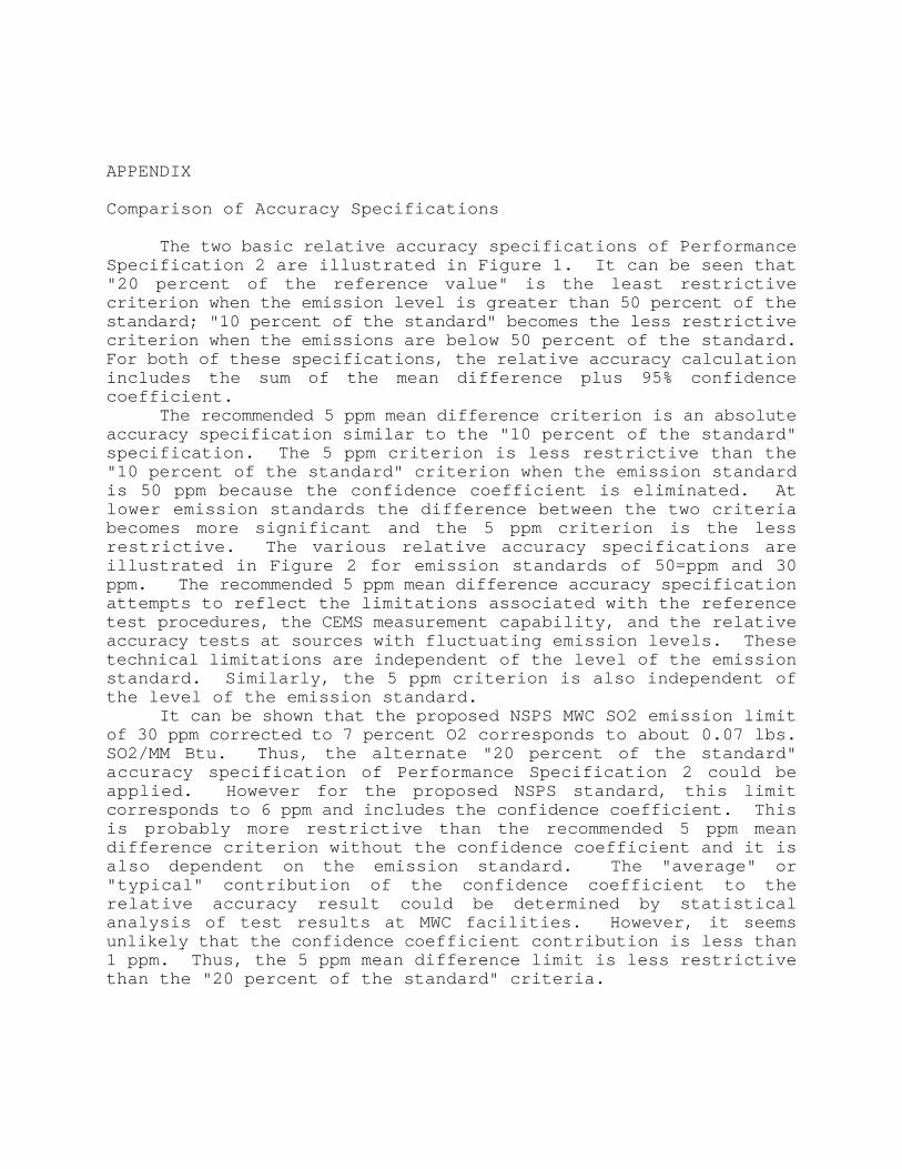
APPENDIX
Comparison of Accuracy Specifications
The two basic relative accuracy specifications of PerformanceSpecification 2 are illustrated in Figure 1. It can be seen that"20 percent of the reference value" is the least restrictivecriterion when the emission level is greater than 50 percent of thestandard; "10 percent of the standard" becomes the less restrictivecriterion when the emissions are below 50 percent of the standard.For both of these specifications, the relative accuracy calculationincludes the sum of the mean difference plus 95% confidencecoefficient.
The recommended 5 ppm mean difference criterion is an absoluteaccuracy specification similar to the "10 percent of the standard"specification. The 5 ppm criterion is less restrictive than the"10 percent of the standard" criterion when the emission standardis 50 ppm because the confidence coefficient is eliminated. Atlower emission standards the difference between the two criteriabecomes more significant and the 5 ppm criterion is the lessrestrictive. The various relative accuracy specifications areillustrated in Figure 2 for emission standards of 50=ppm and 30ppm. The recommended 5 ppm mean difference accuracy specificationattempts to reflect the limitations associated with the referencetest procedures, the CEMS measurement capability, and the relativeaccuracy tests at sources with fluctuating emission levels. Thesetechnical limitations are independent of the level of the emissionstandard. Similarly, the 5 ppm criterion is also independent ofthe level of the emission standard.
It can be shown that the proposed NSPS MWC SO2 emission limitof 30 ppm corrected to 7 percent O2 corresponds to about 0.07 lbs.SO2/MM Btu. Thus, the alternate "20 percent of the standard"accuracy specification of Performance Specification 2 could beapplied. However for the proposed NSPS standard, this limitcorresponds to 6 ppm and includes the confidence coefficient. Thisis probably more restrictive than the recommended 5 ppm meandifference criterion without the confidence coefficient and it isalso dependent on the emission standard. The "average" or"typical" contribution of the confidence coefficient to therelative accuracy result could be determined by statisticalanalysis of test results at MWC facilities. However, it seemsunlikely that the confidence coefficient contribution is less than1 ppm. Thus, the 5 ppm mean difference limit is less restrictivethan the "20 percent of the standard" criteria.
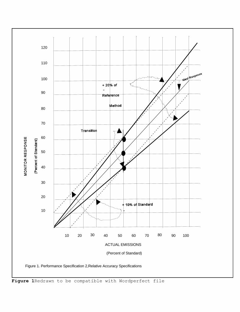
Figure 1. Performance Specification 2,Relative Accuracy Specifications
ACTUAL EMISSIONS
(Percent of Standard)
10 20 30 40 50 60 70 80 90 100
10
20
30
40
50
60
70
80
90
100
110
120
Figure 1Redrawn to be compatible with Wordperfect file

NOTE: I had to redraw the following figures because they were done orginally on aMAC. They are not quite as precise as they should be. If you want a hard copy ofthe orginals, send me a Message on the BBS . Terry Harrison
30 ppm
STD
30 ppm STD
Transition
+
(assumes 2.5 ppm confidence coefficient)
Equivalent 5 ppm Mean Difference Accuracy Criterion-
10 % of 50 ppm STD
(i.e. 5 ppm)+-
10% of 30 ppm STD (i.e. 3 ppm)+-
50 ppm STD
Transition
50 ppm
STD
+-
10 20 30 40 50 60 70 80
ACTUAL EMISSIONS(ppm)
Figure 2. Example Accuracy Specifications for 30 ppm and 50 ppm Standards
10
20
30
40
50
60
70
80
Figure 2 Redrawn to be compatilbe with Wordperfect file.