Embed Size (px)
Citation preview
Commonwealth of Massachusetts
Executive Office of Energy & Environmental Affairs DEPARTMENT OF ENERGY RESOURCES
ALTERNATIVE ENERGY PORTFOLIO STANDARD
GUIDELINE
ON METERING AND CALCULATING THE USEFUL THERMAL OUTPUT OF ELIGIBLE
RENEWABLE THERMAL GENERATION UNITS – PART 2
[Effective Date]
Pursuant to the Alternative Energy Portfolio Standard Regulations at 225 CMR 16.00
This Guideline provides the methods by which the thermal output of intermediate and large
Renewable Thermal Generation Units (RTGUs) qualified for the Alternative Energy Portfolio
Standard (APS) shall be metered and how the meter readings are to be used in conjunction with the
APS renewable thermal alternative energy credit formula to determine the number of Alternative
Energy Credits (AECs) generated. This document is Part 2 of the Guideline on Metering and
Calculating the Useful Thermal Output of Eligible Renewable Thermal Generation Units, Part 1 of
the guideline can be found at the link below.1A Table of Contents, Table of Figures, and List of
Tables can be found immediately following this section.
The purpose of this Guideline is to ensure uniform, accurate, reliable, and verifiable measurements
of RTGU performance for determination of APS benefits, as appropriate to RTGU size and expense.
This Guideline is effective immediately upon issuance. However, the Department of Energy
Resources (Department) may consider exceptions from the Guideline in the case of RTGUs that
went into commercial operation prior to the issuance date, but not earlier than January 1, 2015.
1 Part 1 of the Guideline on Metering and Calculation the Useful Thermal Output of Eligible Renewable Thermal Generation
Units can be found at http://www.mass.gov/eea/energy-utilities-clean-tech/renewable-energy/renewable-thermal/renewable-
heating-and-cooling-alternative-portfolio-std.html

Commonwealth of Massachusetts Guideline on Metering and Calculating the
Department of Energy Resources Useful Thermal Output of Eligible
[Effective Date] Renewable Thermal Generation Units – Part 2
Page 2 of 57
Table of Contents
1) Provisions in the Statute and Regulations ..................................................................................... 6
2) Applicability .................................................................................................................................. 7
3) Metering Requirements and Formulae for Intermediate and Large RTGUs ................................. 9
A) General .................................................................................................................................... 9
1) Quantification of Parasitic Thermal Energy ..................................................................... 11
2) Non Useful Thermal Energy ............................................................................................. 11
3) Locating Btu Meters ......................................................................................................... 11
4) Measuring the Net Renewable Thermal Energy Transferred to a Useful Thermal Load . 12
B) General Formulae for the Quantification of Useful Thermal Energy ................................... 12
C) Metering Information ............................................................................................................ 13
1) Acquisition, Recording, Storing, and Transmittal of Metered Data ................................. 13
2) Meter Standards ................................................................................................................ 13
3) Thermal Energy Meters .................................................................................................... 14
4) Fuel Meters ....................................................................................................................... 16
5) Electric Meters .................................................................................................................. 17
6) Accuracy of Thermal and Fuel Metering .......................................................................... 17
7) Re-calibration of APS meters ........................................................................................... 17
D) Intermediate and Large Solar Hot Water Systems ................................................................ 17
1) Major System Components ............................................................................................... 17
2) Meters ............................................................................................................................... 18
3) Data Acquisition System(s) (DAS) ................................................................................... 18
4) Metering of Intermediate Solar Thermal RTGUs ............................................................. 19
5) Formula for Intermediate Solar Thermal RTGUs ............................................................. 20
6) Metering of Large Solar Thermal RTGUs ........................................................................ 21
7) Formula for Large Solar Thermal RTGUs........................................................................ 22
8) Transpired Solar Air Collector (TSAC) Systems ............................................................. 22
9) Data Acquisition System(s) (DAS) for Intermediate TSAC RTGUs ............................... 23
10) Metering for Intermediate TSAC RTGUs ........................................................................ 23
11) Formula for an Intermediate TSAC RTGU ...................................................................... 24

Commonwealth of Massachusetts Guideline on Metering and Calculating the
Department of Energy Resources Useful Thermal Output of Eligible
[Effective Date] Renewable Thermal Generation Units – Part 2
Page 3 of 57
12) Metering for Large TSAC RTGUs ................................................................................... 26
13) Formula for a Large TSAC RTGUs.................................................................................. 27
E) Intermediate and Large Air Source Heat Pump Systems ...................................................... 27
1) Direct Expansion (DX) Air Source Heat Pumps (ASHPs) ............................................... 27
2) Metering for Intermediate DX ASHPs ............................................................................. 28
3) Formula for Intermediate DX ASHPs............................................................................... 29
4) Metering of Large DX ASHPs .......................................................................................... 30
5) Formula for Large DX ASHPs ......................................................................................... 30
6) Split or Variable Refrigerant Flow (VRF) ASHPs ........................................................... 31
7) Metering for Intermediate Split or VRF AHSPs............................................................... 32
8) Formula for Intermediate Split or VRF ASHPs ................................................................ 32
9) Metering for Large Split or VRF ASHPs ......................................................................... 34
10) Formula for Large Split or VRF ASHPs........................................................................... 35
F) Intermediate and Large Ground Source Heat Pump Systems ............................................... 36
1) Metering for Intermediate GSHPs .................................................................................... 37
2) Formula for Intermediate GSHPs ..................................................................................... 37
3) Metering for Large GSHPs ............................................................................................... 39
4) Formula for Large GSHPs ................................................................................................ 39
G) Intermediate and Large Fired Systems .................................................................................. 40
1) Fired RTGUs which are Combined Heat and Power (CHP) Systems .............................. 41
2) Thermal Storage ................................................................................................................ 42
3) Metering for Intermediate Fired RTGUs, which Generate a Hot Heat Transfer Fluid
and/or Steam ........................................................................................................................... 42
4) Formula for Intermediate Fired RTGUs ........................................................................... 44
5) Firing Modes for Intermediate Fired RTGUs ................................................................... 44
6) Determination of RH for Intermediate RTGUs That Are Not CHP Systems ................... 45
7) Intermediate Fired CHP RTGUs ....................................................................................... 45
8) Large Fired RTGUs which Generate a Hot Heat Transfer Fluid ...................................... 46
9) Metering for Large Fired RTGUs which Generate a Hot Heat Transfer Fluid ................ 46
10) Formulae for a Large, RTGU Generating a Hot Heat Transfer Fluid .............................. 47
11) Firing Modes ..................................................................................................................... 48
12) Large Fired RTGU which Generate Steam ....................................................................... 49

Commonwealth of Massachusetts Guideline on Metering and Calculating the
Department of Energy Resources Useful Thermal Output of Eligible
[Effective Date] Renewable Thermal Generation Units – Part 2
Page 4 of 57
13) General Metering Requirements for Large RTGUs Generating Steam ............................ 50
14) Formula for Large RTGUs Generating Steam .................................................................. 51
H) Compost Vapor Heat Recovery RTGUs ............................................................................... 54
1) Major Components............................................................................................................ 54
2) Metering for Compost Vapor Heat Recovery RTGUs ..................................................... 55
3) Formula for Compost Vapor Recovery RTGUs ............................................................... 56
4) Miscellaneous .............................................................................................................................. 57
Commonwealth of Massachusetts Guideline on Metering and Calculating the
Department of Energy Resources Useful Thermal Output of Eligible
[Effective Date] Renewable Thermal Generation Units – Part 2
Page 5 of 57
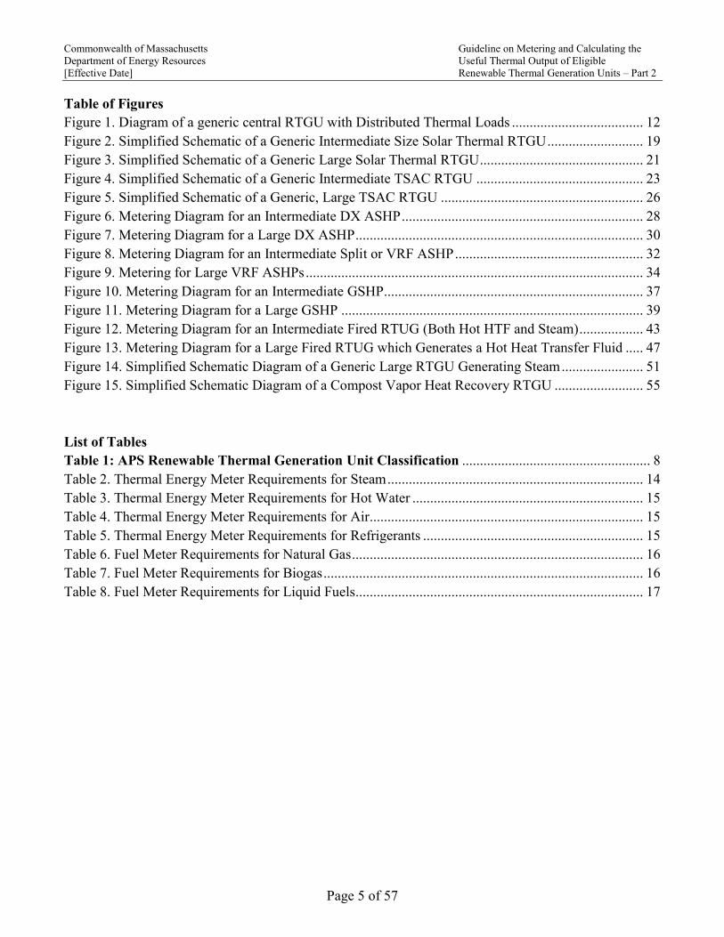
Table of Figures
Figure 1. Diagram of a generic central RTGU with Distributed Thermal Loads ..................................... 12
Figure 2. Simplified Schematic of a Generic Intermediate Size Solar Thermal RTGU ........................... 19
Figure 3. Simplified Schematic of a Generic Large Solar Thermal RTGU .............................................. 21
Figure 4. Simplified Schematic of a Generic Intermediate TSAC RTGU ............................................... 23
Figure 5. Simplified Schematic of a Generic, Large TSAC RTGU ......................................................... 26
Figure 6. Metering Diagram for an Intermediate DX ASHP .................................................................... 28
Figure 7. Metering Diagram for a Large DX ASHP ................................................................................. 30
Figure 8. Metering Diagram for an Intermediate Split or VRF ASHP ..................................................... 32
Figure 9. Metering for Large VRF ASHPs ............................................................................................... 34
Figure 10. Metering Diagram for an Intermediate GSHP......................................................................... 37
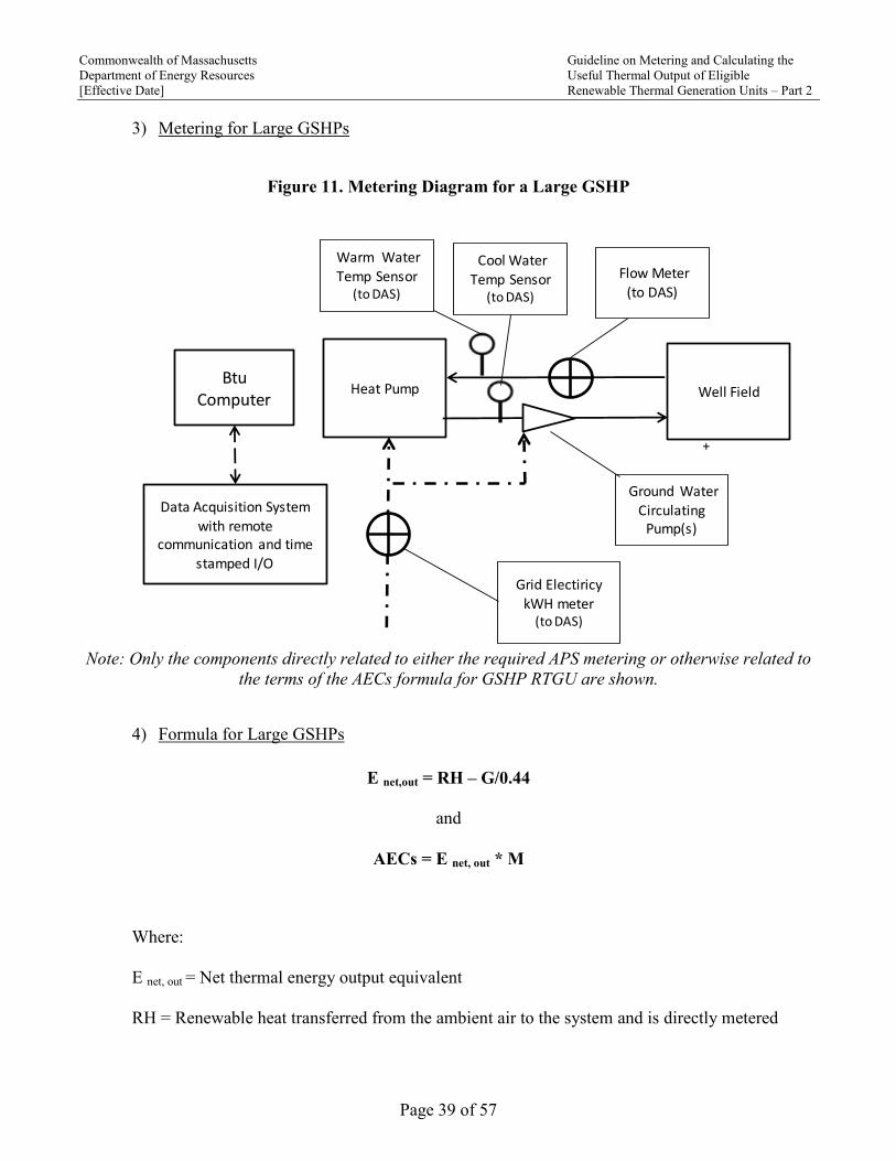
Figure 11. Metering Diagram for a Large GSHP ..................................................................................... 39
Figure 12. Metering Diagram for an Intermediate Fired RTUG (Both Hot HTF and Steam) .................. 43
Figure 13. Metering Diagram for a Large Fired RTUG which Generates a Hot Heat Transfer Fluid ..... 47
Figure 14. Simplified Schematic Diagram of a Generic Large RTGU Generating Steam ....................... 51
Figure 15. Simplified Schematic Diagram of a Compost Vapor Heat Recovery RTGU ......................... 55
List of Tables
Table 1: APS Renewable Thermal Generation Unit Classification ..................................................... 8
Table 2. Thermal Energy Meter Requirements for Steam ........................................................................ 14
Table 3. Thermal Energy Meter Requirements for Hot Water ................................................................. 15
Table 4. Thermal Energy Meter Requirements for Air ............................................................................. 15
Table 5. Thermal Energy Meter Requirements for Refrigerants .............................................................. 15
Table 6. Fuel Meter Requirements for Natural Gas .................................................................................. 16
Table 7. Fuel Meter Requirements for Biogas .......................................................................................... 16
Table 8. Fuel Meter Requirements for Liquid Fuels................................................................................. 17

Commonwealth of Massachusetts Guideline on Metering and Calculating the
Department of Energy Resources Useful Thermal Output of Eligible
[Effective Date] Renewable Thermal Generation Units – Part 2
Page 6 of 57
1) Provisions in the Statute and Regulations
The Alternative Energy Portfolio Standard (APS) statute at M.G.L. Chapter 25A, Section 11F½ (a)2,
as amended by Chapter 251 of the Acts of 2014, mandates the following as an eligible Alternative
Energy Generating Source (emphasis added as italics):
(iv) any facility that generates useful thermal energy using sunlight, biomass, biogas, liquid
biofuel or naturally occurring temperature differences in ground, air or water, whereby 1
megawatt-hour of alternative energy credit shall be earned for every 3,412,000 British thermal
units of net useful thermal energy produced and verified through an on-site utility grade meter or
other means satisfactory to the department;
Pursuant to the verification provision in that language, the APS regulations state the following at 225
CMR 16.05(4):
(b) Metering Requirements. The net Useful Thermal Energy output from an APS Renewable
Thermal Generation Unit shall be metered according to the specifications laid out in the
Department’s Guideline on Metering and Calculating the Useful Thermal Output of Eligible
Renewable Thermal Generation Units and verified by an independent Third Party Meter Reader
as defined in Rule 2.5(j) of the NEPOOL GIS Operating Rules and approved by the Department.
The APS Alternative Generation Attributes reported to the NEPOOL GIS by an independent
Third Party Meter Reader shall be the amount as specified in 225 CMR 16.05(1)(a)6.b. This
amount will be inclusive of any netting of energy use by the APS Renewable Thermal
Generation Unit as prescribed in 225 CMR 16.05(1)(a)6.b.iii., and the application of any
multiplier identified in the Department’s Guideline on Multipliers for Renewable Thermal
Generation Units.
(1) An APS Renewable Thermal Generation Unit that uses more than one eligible
technology in 225 CMR 16.05(1)(a)6.a. is required to use the same independent Third
Party Meter Reader for all technologies.
(2) Each APS Renewable Thermal Generation Unit is required to have its own
individual NEPOOL GIS asset. An APS Renewable Thermal Generation Unit that
uses more than one eligible technology in 225 CMR 16.05(1)(a)6.a. is required to have
a NEPOOL GIS asset for each technology. APS Renewable Thermal Generation Units
that utilize the same technology and are located in the same state may qualify as an
Aggregation and share a NEPOOL GIS asset.
2 The APS statute is available at https://malegislature.gov/Laws/GeneralLaws/PartI/TitleII/Chapter25A/Section11F1~2.
These were amended by sections 1, 2, 3, and 9 of Chapter 251 of the Acts of 2014.

Commonwealth of Massachusetts Guideline on Metering and Calculating the
Department of Energy Resources Useful Thermal Output of Eligible
[Effective Date] Renewable Thermal Generation Units – Part 2
Page 7 of 57
This Guideline specifies the manner by which the output of RTGUs can be verified through on-site
meters which meet the minimum APS metering requirements as described in Section 3 of this document,
or other means as specifically approved by the Department on a case by case basis.
2) Applicability
This document provides general guidance on the type, number, and location of meters specific to
each type of RTGU eligible under the APS. The Department strongly suggests that information
showing the number, type, and location of meters to be installed, be submitted to the Department for
preliminary review prior to the issuance of for bid or for construction designs and/or before
procurement of the meters.
All direct measurements of energy are to be done by meters which comply with the requirements as
set forth in Section 3 of this Guideline. The Department has determined that it is appropriate,
practical, and non-burdensome to require that large RTGUs be fully and directly metered and that a
reduced level of direct metering combined with indirect metering is required for intermediate sized
RTGUs.
The ongoing operation of all RTGUs will be verified through means appropriate for each.
Additionally, the Department has determined that a subset of large RTGUs that use biomass,
biofuels, or biogas can be accurately metered by using fuel input recording, in combination with the
RTGU’s energy conversion efficiency and fuel energy content.
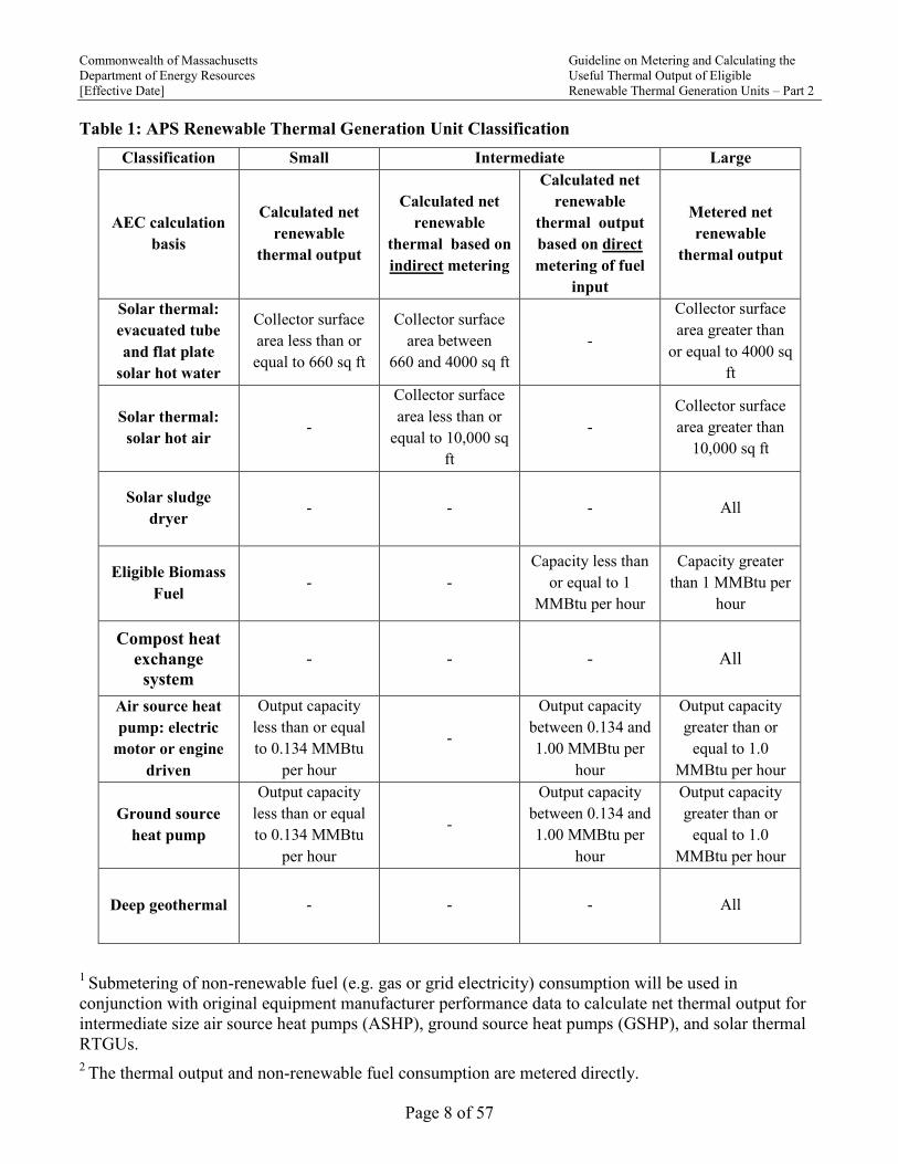
225 CMR 16.05(4)(a) and Table 1 below summarize how RTGUs will be classified based on their
capacity and defines the cut-off points for distinguishing between small, intermediate, and large
RTGUs. The size thresholds apply to the total combined capacity of the RTGU serving the thermal
load. If an RTGU consists of several individual separate units, their capacities will be summed and
the total capacity will be considered against the size threshold. In the case of a combination of solar
thermal and other RTGUs, the thresholds will be applied separately to the solar and non-solar
RTGUs.
Commonwealth of Massachusetts Guideline on Metering and Calculating the
Department of Energy Resources Useful Thermal Output of Eligible
[Effective Date] Renewable Thermal Generation Units – Part 2
Page 8 of 57
Table 1: APS Renewable Thermal Generation Unit Classification
Classification Small Intermediate Large
AEC calculation
basis
Calculated net
renewable
thermal output
Calculated net
renewable
thermal based on
indirect metering
Calculated net
renewable
thermal output
based on direct
metering of fuel
input
Metered net
renewable
thermal output
Solar thermal:
evacuated tube
and flat plate
solar hot water
Collector surface
area less than or
equal to 660 sq ft
Collector surface
area between
660 and 4000 sq ft
-
Collector surface
area greater than
or equal to 4000 sq
ft
Solar thermal:
solar hot air -
Collector surface
area less than or
equal to 10,000 sq
ft
-
Collector surface
area greater than
10,000 sq ft
Solar sludge
dryer - - - All
Eligible Biomass
Fuel - -
Capacity less than
or equal to 1
MMBtu per hour
Capacity greater
than 1 MMBtu per
hour
Compost heat
exchange
system
- - - All
Air source heat
pump: electric
motor or engine
driven
Output capacity
less than or equal
to 0.134 MMBtu
per hour
-
Output capacity
between 0.134 and
1.00 MMBtu per
hour
Output capacity
greater than or
equal to 1.0
MMBtu per hour
Ground source
heat pump
Output capacity
less than or equal
to 0.134 MMBtu
per hour
-
Output capacity
between 0.134 and
1.00 MMBtu per
hour
Output capacity
greater than or
equal to 1.0
MMBtu per hour
Deep geothermal - - - All
1 Submetering of non-renewable fuel (e.g. gas or grid electricity) consumption will be used in
conjunction with original equipment manufacturer performance data to calculate net thermal output for
intermediate size air source heat pumps (ASHP), ground source heat pumps (GSHP), and solar thermal
RTGUs.
2 The thermal output and non-renewable fuel consumption are metered directly.
Commonwealth of Massachusetts Guideline on Metering and Calculating the
Department of Energy Resources Useful Thermal Output of Eligible
[Effective Date] Renewable Thermal Generation Units – Part 2
Page 9 of 57
3 All Biogas/Biofuel RTGUs must apply via an aggregator as described in section 4(H) below.
4 Output heating capacity at entering source air temperature of 5°F
5 The performance of intermediate and large air source heat pump units must be Air-Conditioning and
Heating Institute (AHRI) certified. 6
If AHRI Certificate exists, output heating capacity as indicated on the AHRI Certificate at Full Load.
If AHRI Certificate does not exist, use manufacturer’s rated output heating capacity as indicated below:
(a) For closed loop, water to water heat pumps: capacity at source entering water temperature
of 32°F and load entering water temperature of 104°F If multiple ratings are shown under
these conditions, use the source water and load water flow rate that results in the largest
heating capacity.
(b) For open loop water to water heat pumps: capacity at source entering water temperature
of 50°F and load entering water temperature of 104°F. If multiple ratings are shown
under these conditions, use the source water and load water flow rate that results in the
largest heating capacity.
(c) For closed loop, water to air heat pumps, capacity at source entering water temperature of
32°F and load entering air temperature of 70°F. If multiple ratings are shown under these
conditions, use the source water and load air flow rate that results in the largest heating
capacity.
(d) For open loop, water to air heat pumps, capacity at source entering water temperature of
50°F and load entering air temperature of 70°F. If multiple ratings are shown under these
conditions, use the source water and load air flow rate that results in the largest heating
capacity.
For the purpose of this Guideline, the definition of closed loop and open loop are as follows:
Close loop: Any water to air or water to water ground source heat pump system having
no direct contact between the groundwater and the system fluid used for heat exchange.
Open loop: Any water to air or water to water ground source heat pump system which
uses groundwater as the fluid for heat exchange.
3) Metering Requirements and Formulae for Intermediate and Large RTGUs
A) General
The British Thermal Unit (Btu) is a unit of thermal energy commonly used in the
quantification of the capacity of a RTGU, as well as for the input and output energy of a
system and/or component.
All of the energy terms in the APS formulae for the determination of AECs are to be
expressed in megawatt hours (MWh).
Commonwealth of Massachusetts Guideline on Metering and Calculating the
Department of Energy Resources Useful Thermal Output of Eligible
[Effective Date] Renewable Thermal Generation Units – Part 2
Page 10 of 57
1 Btu = 1/3.412 watt hour; 1 MMBtu = 1,000,000 Btu = 1/3.412 MWh
Net useful heat is the thermal energy by a RTGU that is transferred to a facility and/or
process load and is equal to the thermal energy supplied to the load from the RTGU minus
thermal energy returned from the load to the RTGU minus any parasitic thermal energy.
RTGUs which are Combined Heat and Power (CHP) Systems:
An RTGU which co-generates electricity and useful heat is designated as a CHP RTGU and
may qualify for Massachusetts Portfolio Standard Programs and earn credits in one of two
different ways:
(a) A CHP RTGU may qualify as a Renewable Portfolio Standard (RPS) Class I generator
and as an APS RTGU In this case:
(i) The net MWh electricity generated by the CHP RTGU earns Class I Renewable
Energy Credits (RECs)
(ii) The net useful heat generated by the CHP RTGU earns one AEC per net MWh of
useful heat transferred to a useful load
(b) A CHP RTGU may qualify as a RPS Class I generator and as an APS CHP system per
the regulations in CMR 225 16.00 that pertain to APS CHP systems and the related
Guidelines. In this case:
(i) The net MWh of electricity generated by the CHP RTGU earns Class I RECs
(ii) The net MWh of electricity and the net MWh of useful heat generated by the unit
earn AECs per the APS CHP formula as shown in the APS CHP regulations
All electricity supplied by the ISO-NE grid to a RTGU including any auxiliary systems is
considered to be non-renewable fuel and must be subtracted from the net useful heat
generated. The amount of non-renewable source fuel per MWh of grid electricity consumed
by a RTGU is equal to the MWh electricity consumed at the site divided by the most recently
published ISO-NE marginal grid efficiency, which at the date of this version of this
Guideline is 0.44 MWh source fuel/MWh electricity delivered.
The term auxiliary denotes a component and/or sub-system that does not directly generate
Useful Thermal Energy, but whose operation is required in order for the generation of Useful
Thermal Energy to occur. Examples of auxiliary components are:
Boiler feedwater pumps
Combustion air supply fans
Biomass boiler stokers
Solar thermal collector fluid circulating pumps
In general, components such as pumps, fans, blowers, etc. that may be installed and operated
in conjunction with an RTGU whose function is to distribute the thermal energy generated by
an RTGU to the useful thermal loads, are not considered as auxiliary and the energy required
to operate them is not metered or included in the determination of AECs.
Exception: If a RTGU is located more than 500 ft. from the point of connection with a
thermal load or with the thermal hosts’ distribution system being supplied by the RTGU, the

Commonwealth of Massachusetts Guideline on Metering and Calculating the
Department of Energy Resources Useful Thermal Output of Eligible
[Effective Date] Renewable Thermal Generation Units – Part 2
Page 11 of 57
grid sourced electricity supplied to circulate heat transfer fluid between a central RTGU and
the point of connection with each remote building or self-contained load is to be subtracted
from the net renewable useful heat transferred.
Parasitic Energy is defined as the electricity or thermal energy that is generated by the RTGU
which is used to operate any auxiliary component or system of the RTGU.
Parasitic electricity is typically applicable only to a CHP RTUG. Metering and quantification of
parasitic electricity for CHP systems that qualify using option 1 or 2 ( see above) will conform
as are applicable to the APS CHP and RPS Class 1 regulations and guidelines. Parasitic thermal
energy may be applicable to all RTGUs; however it is typically limited to RTGUs which
generate motive steam.
1) Quantification of Parasitic Thermal Energy
All efforts should be made to locate a system’s Btu meters such that the consumption of
parasitic thermal energy is netted out. In the event that this cannot be accomplished the
parasitic thermal energy of any auxiliary system with a demand exceeding 5% of the projected
value of the net annual AECs during nominal operating conditions will require either a
calculation of the parasitic load or a separate Btu meter. This determination will be at the
discretion of the Department.
2) Non Useful Thermal Energy
Renewable thermal energy that is rejected to a heat sink (e.g. the air, ground, surface, or storm
water), or in most cases, to heat feedwater, is non Useful Thermal Energy and must be
accounted for in the location of Btu meter instruments as well as in the determination of the net
metered useful energy.
Wherever possible, the components of Btu meters should be located such that they do not
count heat rejected to a heat sink or in most cases to heat feedwater, in the heat being metered
as useful. If this is not possible, separate Btu metering will be required to measure the heat
rejected to a heat sink and this energy shall be subtracted from the total metered Btus.
3) Locating Btu Meters
a) Whenever possible, Btu meters should be located at a point before the interconnection
with the load’s thermal distribution system (i.e. on the RTGU side and not on the load
side).
b) Whenever possible, Btu meters should be located before any point of connection with
a non-useful heat load, such as a radiator of cooling tower that rejects excess heat,
before delivery to the distribution system, or rejection of excess heating systems.
c) When a RTGUs is located more than 500 ft from the point of connection with a
thermal load, the Btu meter(s) must be located within 30 feet from the point of
connection to the thermal load

Commonwealth of Massachusetts Guideline on Metering and Calculating the
Department of Energy Resources Useful Thermal Output of Eligible
[Effective Date] Renewable Thermal Generation Units – Part 2
Page 12 of 57
. Figure 1. Diagram of a generic central RTGU with Distributed Thermal Loads
4) Measuring the Net Renewable Thermal Energy Transferred to a Useful Thermal Load
(a) Air or Heat Transfer Fluids (including aqueous mixtures): based on mass flow,
temperature, and specific heat
(b) Steam: based on mass flow and specific enthalpy
B) General Formulae for the Quantification of Useful Thermal Energy
Enet, out = (RH – NUH – Pth – G/0.44)
Note: All terms are the cumulative as-metered values. Unless otherwise indicated, all units in
MWh
Where:
E net, out = Net thermal energy output equivalent
RH = Net renewable heat transferred to a useful load
NUH = Non-useful heat
Pth = Parasitic thermal energy
Commonwealth of Massachusetts Guideline on Metering and Calculating the
Department of Energy Resources Useful Thermal Output of Eligible
[Effective Date] Renewable Thermal Generation Units – Part 2
Page 13 of 57
G = Grid supplied electrical energy
Conversion of site to source nonrenewable fuel per MWh grid electricity = G / (0.44)
C) Metering Information
1) Acquisition, Recording, Storing, and Transmittal of Metered Data
All RTGUs must include a data acquisition system (DAS) which must meet the following
minimum functional criteria:
(a) Input: Input must come from each APS metering system and component, at an interval
that does not to exceed 5 minute between inputs
(b) Storage: 100 days of cumulative input data
(c) Output:
(i) Have remote electronic access to time stamped data of each input in five minute
intervals that can be exported as a comma separated values (.csv) file
(ii) Data is to be accessible by and transferred directly to the system Independent
Verifier and not via a third party
The DAS may be a stand-alone dedicated unit or be integrated into an existing system.
2) Meter Standards
All meters required by the APS must meet and conform to all applicable laws, ordinances, codes,
regulations, and standards, must be of revenue grade accuracy, quality, and reliability, and must
have the capability to generate and transmit a signal to the system DAS.

Commonwealth of Massachusetts Guideline on Metering and Calculating the
Department of Energy Resources Useful Thermal Output of Eligible
[Effective Date] Renewable Thermal Generation Units – Part 2
Page 14 of 57
3) Thermal Energy Meters
Table 2. Thermal Energy Meter Requirements for Steam
Line
Size
Btu Meter System Components System
Field
Accuracy
Re-
Calibration
Interval
Notes
Flow Sensor and
Btu Computer
Temperature
& Pressure
Sensors
All
Btu Computer:
Automated real-
time
computation and
totalizer
__
__
≥8"
Flow Sensor:
Orifice Plate
with Differential
Pressure
Element and
Transmitter
Only with
superheated
Steam
±3%
Annual
with
Orifice
Plate flow
meter;
Biennial
with
Vortex
Shedding
flow meter
1) Perform an annual inspection of
the flow sensor orifice plates and
check for wear and distortion
beyond the OEMs specifications as
a part of the annual re-calibration
procedure
2) If a significant percentage of
flow occurs at flow rates below the
flow sensors minimum guaranteed
full accuracy flow rate, both the
flow and Btus may be
undercounted. This can be
addressed by installing a two meter
manifold with the meters sized to
cover the entire expected range of
flow rates. Consult the flow meter
provider for design and installation
details
< 8"
Flow Sensor:
Vortex Shedding
Tube
Only with
superheated
Steam
__

Commonwealth of Massachusetts Guideline on Metering and Calculating the
Department of Energy Resources Useful Thermal Output of Eligible
[Effective Date] Renewable Thermal Generation Units – Part 2
Page 15 of 57
Table 3. Thermal Energy Meter Requirements for Hot Water
Btu Meter System Components Btu Meter
Field Accuracy
Re- Calibration
Interval Notes
Flow Sensor:
In-line Ultrasonic Flow Tube (no strap-on)
or Magmeter
Thermal Sensors: Installed in thermowells
Btu Computer: Automated real-time
computation and totalizer
±3% Biennial
No turbine or
impellor based flow
sensors
Table 4. Thermal Energy Meter Requirements for Air
Btu Meter System Components Btu Meter
Field Accuracy
Re-
Calibration
Interval
Notes
Flow Sensor:
a) In-duct Differential Pressure Measuring
Airflow Station
b) Pitot Tube
Thermal Sensors: Installed in the air flow
stream
Btu Computer: Automated real-time
computation and totalizer
±3%**
Annual
Clean and inspect
orifices as a part of
the annual
calibration
procedure
**Computed accuracy of the metered Btus excludes the transfer of latent heat, which is calculated and
added to the as metered value by the independent verifier based on hourly relative humidity
measurements obtained from the NOAA Local Climatological Data available from the Land Based
Station located closest to the RTGU.**
Table 5. Thermal Energy Meter Requirements for Refrigerants
Btu Meter System Components Btu Meter
Field Accuracy
Re-
Calibration
Interval
Notes
Liquid Flow Sensor: Full Flow Ultrasonic
(transit time)
Thermal Sensors: RTD or Thermocouple
Installed in thermowells
Btu Computer: Automated real-time
computation and totalizer
±3% TBD
Care must be taken
to avoid flashing of
the hot liquid to
vapor, which will
affect the operation
of expansion valves
Commonwealth of Massachusetts Guideline on Metering and Calculating the
Department of Energy Resources Useful Thermal Output of Eligible
[Effective Date] Renewable Thermal Generation Units – Part 2
Page 16 of 57
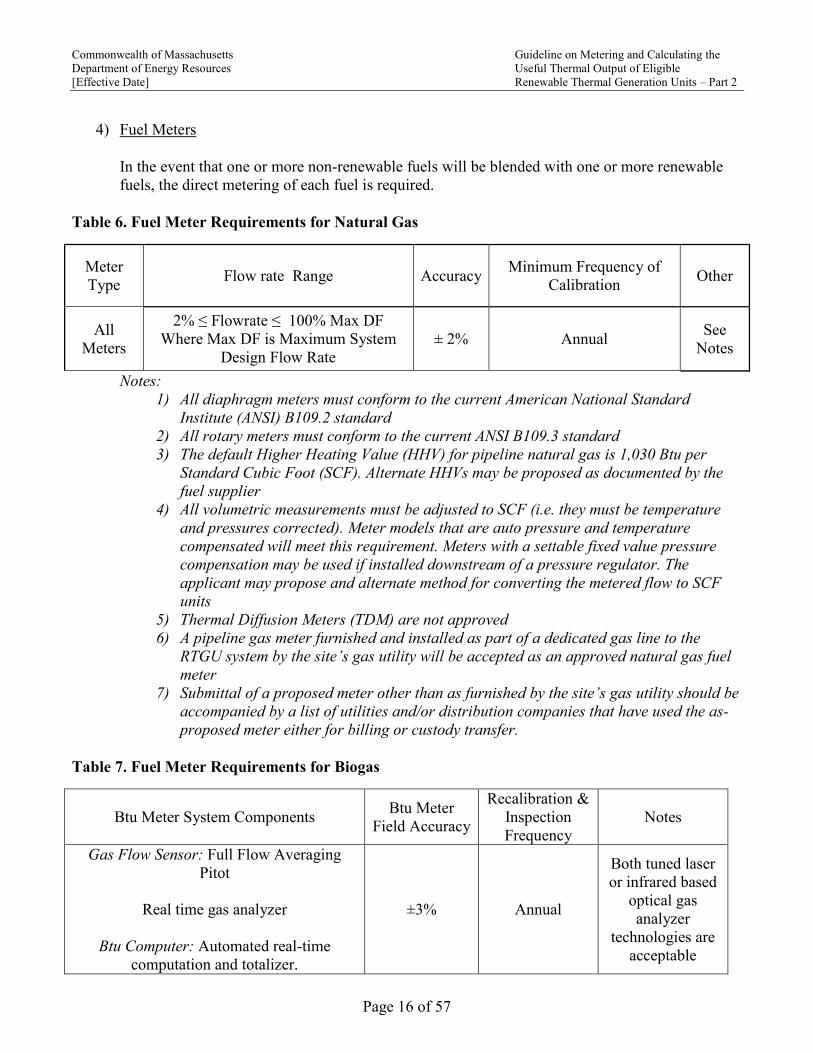
4) Fuel Meters
In the event that one or more non-renewable fuels will be blended with one or more renewable
fuels, the direct metering of each fuel is required.
Table 6. Fuel Meter Requirements for Natural Gas
Meter
Type
Flow rate Range
Accuracy Minimum Frequency of
Calibration Other
All
Meters
2% ≤ Flowrate ≤ 100% Max DF
Where Max DF is Maximum System
Design Flow Rate
± 2% Annual See
Notes
Notes:
1) All diaphragm meters must conform to the current American National Standard
Institute (ANSI) B109.2 standard
2) All rotary meters must conform to the current ANSI B109.3 standard
3) The default Higher Heating Value (HHV) for pipeline natural gas is 1,030 Btu per
Standard Cubic Foot (SCF). Alternate HHVs may be proposed as documented by the
fuel supplier
4) All volumetric measurements must be adjusted to SCF (i.e. they must be temperature
and pressures corrected). Meter models that are auto pressure and temperature
compensated will meet this requirement. Meters with a settable fixed value pressure
compensation may be used if installed downstream of a pressure regulator. The
applicant may propose and alternate method for converting the metered flow to SCF
units
5) Thermal Diffusion Meters (TDM) are not approved
6) A pipeline gas meter furnished and installed as part of a dedicated gas line to the
RTGU system by the site’s gas utility will be accepted as an approved natural gas fuel
meter
7) Submittal of a proposed meter other than as furnished by the site’s gas utility should be
accompanied by a list of utilities and/or distribution companies that have used the as-
proposed meter either for billing or custody transfer.
Table 7. Fuel Meter Requirements for Biogas
Btu Meter System Components Btu Meter
Field Accuracy
Recalibration &
Inspection
Frequency
Notes
Gas Flow Sensor: Full Flow Averaging
Pitot
Real time gas analyzer
Btu Computer: Automated real-time
computation and totalizer.
±3% Annual
Both tuned laser
or infrared based
optical gas
analyzer
technologies are
acceptable

Commonwealth of Massachusetts Guideline on Metering and Calculating the
Department of Energy Resources Useful Thermal Output of Eligible
[Effective Date] Renewable Thermal Generation Units – Part 2
Page 17 of 57
Table 8. Fuel Meter Requirements for Liquid Fuels
Meter Type Flow rate
Accuracy
Minimum Frequency of
Calibration Other
Positive
Displacement Full
Range ± 1% Annual
See general and specific
Notes.
5) Electric Meters
Electric (kWh) meters shall be revenue grade and shall:
(a) Be certified as meeting American National Standard Institute (ANSI) Standard C12.20
(b) Have a kW and kWh remote output signal with an output signal interval of not more
than once per minute
(c) Have either a non-resettable or password protected cumulative kWh register
6) Accuracy of Thermal and Fuel Metering
Thermal energy and fuel must be metered per the tables in 3(F) and 3(G) above, with a possible
future modification per the issuance of the American Society for Testing and Materials (ASTM)
Heat Meter Technology Standard WK37952 that is currently under development under the
leadership of the United States Environmental Protection Agency (EPA).
7) Re-calibration of APS meters
The options for re-calibration of all APS meters are:
(a) Remove the meter and have it re-calibrated either by the meter OEM or by a calibration shop
that is approved by the meter OEM. If this option is selected, in order to be for the RTGU to
be able to generate AECs during the interval in which an APS meter is removed for
calibrations, either a temporary meter that meets the APS requirements must be installed or a
proposed method and procedure to estimate the metered energy must be submitted to the
DOER for approval prior to the removal of the meter.
(b) The meter may be re-calibrated in situ providing that that this is done per instructions and
procedures provided by the OEM and that the re-calibration is performed by a technician
either directly provided by the OEM or approved by the OEM. Evidence that this conditions
have been complied with must be included in the re-calibration report.
D) Intermediate and Large Solar Hot Water Systems
1) Major System Components

Commonwealth of Massachusetts Guideline on Metering and Calculating the
Department of Energy Resources Useful Thermal Output of Eligible
[Effective Date] Renewable Thermal Generation Units – Part 2
Page 18 of 57
Intermediate and large solar hot water RTGUs include, but are not limited to, the following
major components:
(a) A solar thermal energy collector system
(b) One or more unfired water storage tanks that supply water, pre-heated by solar energy
only, to a primary (fired) heating system
(c) Heat exchanger(s) which transfer energy from the solar collector heat transfer fluid
circulating loop to the volume of water in the pre-heat storage tank (not shown in
Figure 2 below)
(d) Electric motor driven pump(s) which circulate a heat transfer fluid in a closed loop
between the solar collectors and the collector fluid-to-unfired storage tank heat
exchanger
(e) Automatic pump controller(s) which start and stop the circulating pumps based on a
pre-set temperature difference between the temperature of the un-fired storage tank and
the temperature of the solar collectors
2) Meters
All intermediate and large solar hot water RTGUs must have Btu and kWh meters as shown
in Figure 2 and Figure 3.
3) Data Acquisition System(s) (DAS)
An eligible DAS must meet the requirements in Section 3(D) above record, store, and
transmit time stamped Btu meter readings, and the run times of the collector heat transfer
fluid circulating pump(s).
These are based on the generic configurations as shown in Figure 2 and Figure 3. The
Department will evaluate metering plans and submittals based on alternative configurations
on a case-by-case basis.

Commonwealth of Massachusetts Guideline on Metering and Calculating the
Department of Energy Resources Useful Thermal Output of Eligible
[Effective Date] Renewable Thermal Generation Units – Part 2
Page 19 of 57
Figure 2. Simplified Schematic of a Generic Intermediate Size Solar Thermal RTGU
4) Metering of Intermediate Solar Thermal RTGUs
Refer to Figure 2Error! Reference source not found..
(a) The systems heat transfer fluid (HTF) supply temperature (HTFST) & HTF return
temperature (HTFRT) will be measured directly with thermal sensors located at the collector
array and the bottom of the unfired storage tank
(b) Any grid supplied electrical energy (G) must be directly metered
(c) After the circulating HTF system has set and balanced, the system flow rate will be
determined and recorded by the installer using a temporary calibrated flow meter used to
measure the flow rate for each pumped HTF loop. The temporary meter must be an in-line
model and can be a turbine meter.
Pump (s) Load
Load
Temperature
kWh
Meter
Pump
Controller
DAS with remote
communicationand time
stamped I/O
Collector
TemperatureSolar Collector Array
Commonwealth of Massachusetts Guideline on Metering and Calculating the
Department of Energy Resources Useful Thermal Output of Eligible
[Effective Date] Renewable Thermal Generation Units – Part 2
Page 20 of 57
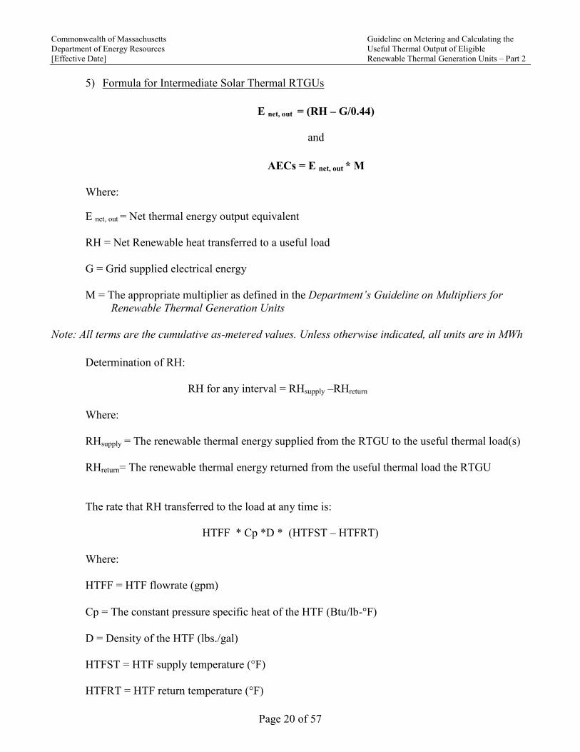
5) Formula for Intermediate Solar Thermal RTGUs
E net, out = (RH – G/0.44)
and
AECs = E net, out * M
Where:
E net, out = Net thermal energy output equivalent
RH = Net Renewable heat transferred to a useful load
G = Grid supplied electrical energy
M = The appropriate multiplier as defined in the Department’s Guideline on Multipliers for
Renewable Thermal Generation Units
Note: All terms are the cumulative as-metered values. Unless otherwise indicated, all units are in MWh
Determination of RH:
RH for any interval = RHsupply –RHreturn
Where:
RHsupply = The renewable thermal energy supplied from the RTGU to the useful thermal load(s)
RHreturn= The renewable thermal energy returned from the useful thermal load the RTGU
The rate that RH transferred to the load at any time is:
HTFF * Cp *D * (HTFST – HTFRT)
Where:
HTFF = HTF flowrate (gpm)
Cp = The constant pressure specific heat of the HTF (Btu/lb-°F)
D = Density of the HTF (lbs./gal)
HTFST = HTF supply temperature (°F)
HTFRT = HTF return temperature (°F)

Commonwealth of Massachusetts Guideline on Metering and Calculating the
Department of Energy Resources Useful Thermal Output of Eligible
[Effective Date] Renewable Thermal Generation Units – Part 2
Page 21 of 57
6) Metering of Large Solar Thermal RTGUs
Figure 3. Simplified Schematic of a Generic Large Solar Thermal RTGU
Note: System heat exchangers not shown for clarity
Pump Controller Thermal Sensor
APS Btu Meter Thermal Sensor
APS Meter
Pump (s)
Collector Temperature
Unfired
Solar HW Storage
Pump Controller
Storage Temperature
kWh
Meter(s)
Pump
Controller
Fired
WaterHeating
System (s)
Hot Water
Loads
Btu Meter
Hot Water
Btu Meter
Cold Water
Data Acquisition
System with remote communication and
time stamped I/O
Btu Meter
Computer
City Cold
Makeup Water
Collector Array

Commonwealth of Massachusetts Guideline on Metering and Calculating the
Department of Energy Resources Useful Thermal Output of Eligible
[Effective Date] Renewable Thermal Generation Units – Part 2
Page 22 of 57
7) Formula for Large Solar Thermal RTGUs
E net, out = (RH – G/0.44)
and
AECs = E net, out * M
Where:
E net, out = Net thermal energy output equivalent
RH = Net Renewable heat transferred to a useful load
G = Grid supplied electrical energy
Conversion of site to source nonrenewable fuel per MWh grid electricity = G / (0.44)
M = The appropriate multiplier as defined in the Department’s Guideline on Multipliers for
Renewable Thermal Generation Units
Note: All terms are the cumulative as-metered values. Unless otherwise indicated, all units in MWh
The rate that RH is transferred to the load at any time is:
(CMWF * 8.34 (lbs/gal) * (TSHW – TCMW)) / 3.412E6 (Btu/MWh)
Where:
CMWF = City cold makeup water flow rate (gallons per minute)
TCMW = Temperature of the city cold makeup water supply (°F)
TCMW = Temperature of the solar hot water supplied by the unfired solar storage tank to the
fired hot water storage tank (°F)
8) Transpired Solar Air Collector (TSAC) Systems
TSAC RTGUs transfer solar energy to preheat the outside air supply to a heated space. Major
system components for both intermediate and large TSAC RTGUs include, but are not limited to,
the following major components:
(a) Transpired Solar Air Collector(s)
(b) Ducting from collector to ventilation unit
(c) Bypass Air intake to ventilation
(d) ON/OFF Solar Air Collector Damper and ON/OFF Bypass Air Damper

Commonwealth of Massachusetts Guideline on Metering and Calculating the
Department of Energy Resources Useful Thermal Output of Eligible
[Effective Date] Renewable Thermal Generation Units – Part 2
Page 23 of 57
(e) Automatic Controls
(f) Ventilation Unit (Typically an existing Air Handling Unit, Make-Up Air Unit, In-Line
Supply Fan
9) Data Acquisition System(s) (DAS) for Intermediate TSAC RTGUs
An eligible DAS must meet the requirements in Section 3(D) above and record, store, and
transmit time stamped Btu meter readings and the run times of the collector heat transfer
fluid circulating pump(s).
These are based on the generic configurations as shown in Figure 4 and Figure 5. The
Department will evaluate metering plans and submittals based on alternative configurations
on a case-by-case basis.
10) Metering for Intermediate TSAC RTGUs
Figure 4. Simplified Schematic of a Generic Intermediate TSAC RTGU

Commonwealth of Massachusetts Guideline on Metering and Calculating the
Department of Energy Resources Useful Thermal Output of Eligible
[Effective Date] Renewable Thermal Generation Units – Part 2
Page 24 of 57
11) Formula for an Intermediate TSAC RTGU
Enet, out = RH - G/0.44
and
AECs = E net, out * M
Where:
E net, out = Net thermal energy output equivalent
RH = Renewable heat transferred from the ambient air to a useful and is not directly metered
G = Grid supplied electrical energy
Conversion of site to source nonrenewable fuel per MWh grid electricity = G / (0.44)
M = The appropriate multiplier as defined in the Department’s Guideline on Multipliers for
Renewable Thermal Generation Units
Note: All terms are the cumulative as-metered values. Unless otherwise indicated, all units in MWh
Determination of RH
RH over any interval = A*D*Cp* (TTSA – TAMBIENT)/3.412E6 (Btu/MWh)
Where:
A = Air Flow (cubic feet)
D= Density of Air (lbs/cf)
Cp = Specific Heat Capacity of Air (Btu/lb -°F)
TTSA = Temperature of the hot air generated by the TSAC (°F)
TAMBIENT = Ambient Air Temperature (°F)
The TSAC RTGU hot air output flow rate is not directly metered. Whenever the TSAC RTGU by-pass
damper is open and the existing system ventilation fan is running the outside air which is pre-heated by
the TSAC RTGU is supplied to the space heating load.

Commonwealth of Massachusetts Guideline on Metering and Calculating the
Department of Energy Resources Useful Thermal Output of Eligible
[Effective Date] Renewable Thermal Generation Units – Part 2
Page 25 of 57
The TSAC RTGU hot air output flow rate is indexed to the position of the return air damper(s) which
sets the percentage of outside air supplied to the load that is mixed with the return air from the heated
space.
During the initial test and balance section of the initial commissioning of the TSCA RTGU, the supplier
will develop and provide a certified lookup table which indexes the flowrate of TSCA generated pre-
heated air to the position of the return air damper from 0% to 100% open in increments of 5%. In order
to maintain an approved status for a TSAC RTGU, the table will be re-calibrated on site, revised as
needed and provided to the Department on an annual basis.
The rate of renewable heat transfer to a useful load at any time:
D* Cp * (TTSA – TAMBIENT) * DPSAH *OAF * FSTATUS
Where:
D= Density of Air (lbs/cf)
Cp = Specific Heat Capacity of Air (Btu/lb -°F}
TTSA = Temperature of the hot air generated by the TSAC (°F)
TAMBIENT = Ambient Air Temperature (°F)
DPSAH = TSAC RTGU By-pass damper position, (OPEN = 1, CLOSED = 0)
OAF = Flow rate of pre-heated air supplied by the TSAC RTGU as determined by the position of
the return air damper
FSTATUS = Ventilation Unit Fan Status (ON = 1, OFF = 0)

Commonwealth of Massachusetts Guideline on Metering and Calculating the
Department of Energy Resources Useful Thermal Output of Eligible
[Effective Date] Renewable Thermal Generation Units – Part 2
Page 26 of 57
12) Metering for Large TSAC RTGUs
Figure 5. Simplified Schematic of a Generic, Large TSAC RTGU
Commonwealth of Massachusetts Guideline on Metering and Calculating the
Department of Energy Resources Useful Thermal Output of Eligible
[Effective Date] Renewable Thermal Generation Units – Part 2
Page 27 of 57
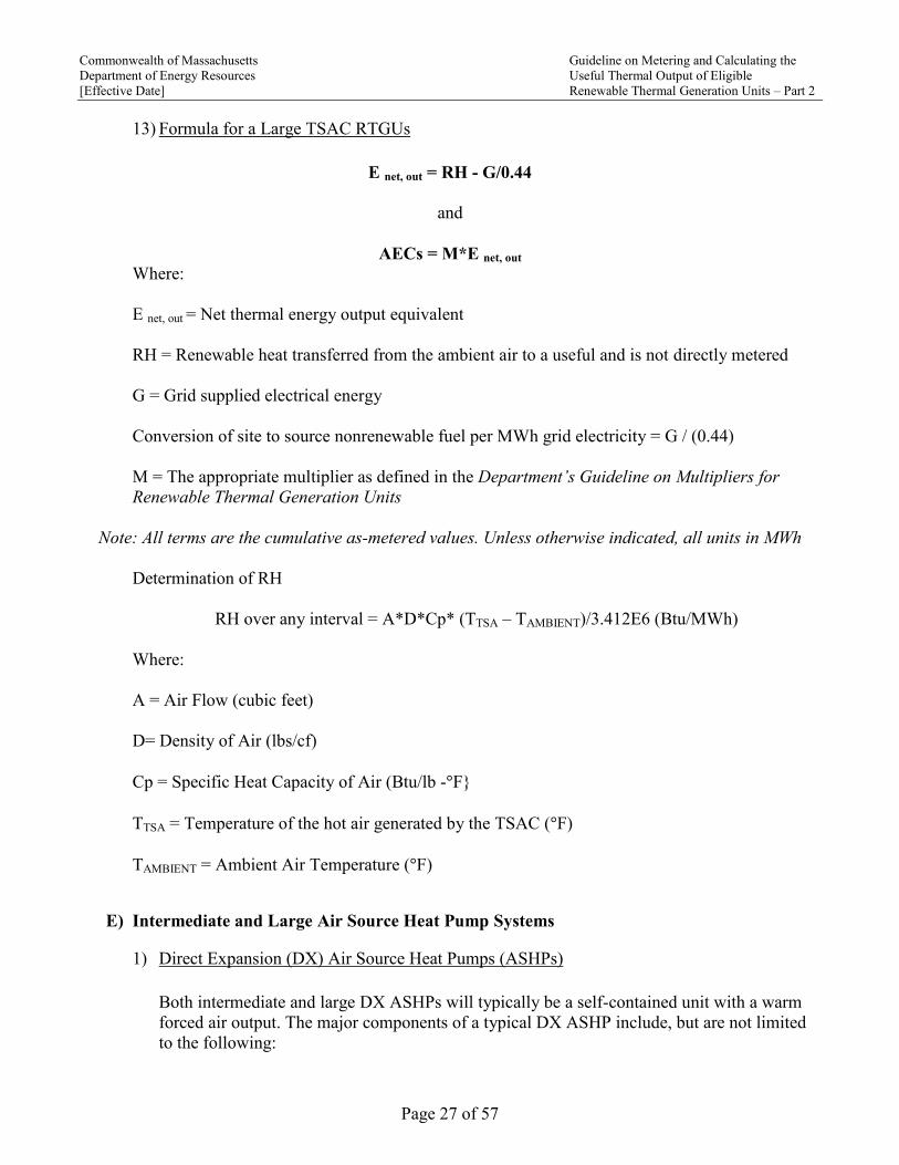
13) Formula for a Large TSAC RTGUs
E net, out = RH - G/0.44
and
AECs = M*E net, out Where:
E net, out = Net thermal energy output equivalent
RH = Renewable heat transferred from the ambient air to a useful and is not directly metered
G = Grid supplied electrical energy
Conversion of site to source nonrenewable fuel per MWh grid electricity = G / (0.44)
M = The appropriate multiplier as defined in the Department’s Guideline on Multipliers for
Renewable Thermal Generation Units
Note: All terms are the cumulative as-metered values. Unless otherwise indicated, all units in MWh
Determination of RH
RH over any interval = A*D*Cp* (TTSA – TAMBIENT)/3.412E6 (Btu/MWh)
Where:
A = Air Flow (cubic feet)
D= Density of Air (lbs/cf)
Cp = Specific Heat Capacity of Air (Btu/lb -°F}
TTSA = Temperature of the hot air generated by the TSAC (°F)
TAMBIENT = Ambient Air Temperature (°F)
E) Intermediate and Large Air Source Heat Pump Systems
1) Direct Expansion (DX) Air Source Heat Pumps (ASHPs)
Both intermediate and large DX ASHPs will typically be a self-contained unit with a warm
forced air output. The major components of a typical DX ASHP include, but are not limited
to the following:

Commonwealth of Massachusetts Guideline on Metering and Calculating the
Department of Energy Resources Useful Thermal Output of Eligible
[Effective Date] Renewable Thermal Generation Units – Part 2
Page 28 of 57
(a) Controls
(b) A closed refrigerant sub-system including:
(i) Compressor(s)
(ii) Evaporator(s)
(iii)Condenser(s)
(iv) JT expansion valves
(v) Refrigerant side tubing, instruments and control devices
(c) An air side sub-system including:
(i) Fans
(ii) Louvers and dampers
(iii)Filters
(iv) Air flow related internal ducting, instruments, and control devices
2) Metering for Intermediate DX ASHPs
Figure 6. Metering Diagram for an Intermediate DX ASHP
DX Air Source Heat Pump
Return Air
Duct From Building
Make up
Outside Air
Main Heat Pump Supply Air
Duct To Building Heatiing Distribution System
Blended
Supply Air to Condendsor
Non-renewable Fuel
Meter ( Grid electricty or other)
Data Acquisition
System with remote communication and
time stamped I/O
Btu
Computer
Mixing Box
Condenser (Heating)
Coil
Evapaporator (Cooling)
Coil
Temperature
Sensor (signal to
DAS
Outside Air

Commonwealth of Massachusetts Guideline on Metering and Calculating the
Department of Energy Resources Useful Thermal Output of Eligible
[Effective Date] Renewable Thermal Generation Units – Part 2
Page 29 of 57
3) Formula for Intermediate DX ASHPs
E net, out = (COPOAT * G) – G/0.44)
and
AECs = E net, out* M
Where:
E net, out = Net thermal energy output equivalent
COPOAT. = The book value of the coefficient of performance at the outside air temperature as
measured at the RTGU
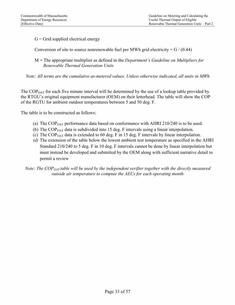
G = Grid supplied electrical energy
Conversion of site to source nonrenewable fuel per MWh grid electricity = G / (0.44)
M = The appropriate multiplier as defined in the Department’s Guideline on Multipliers for
Renewable Thermal Generation Units
Note: All terms are the cumulative as-metered values. Unless otherwise indicated, all units in MWh
The COPOAT for each five minute interval will be determined by the use of a lookup table provided by
the RTGU’s OEM on their letterhead. The table will show the COP of the RGTU for ambient outdoor
temperatures between 5 and 50 deg. F.
The table is to be constructed as follows:
(a) The COPOAT performance data based on conformance with AHRI 210/240 is to be used
(b) The COPOAT data is subdivided into 15 deg. F intervals using a linear interpolation
(c) The COPOAT data is extended to 60 deg. F in 15 deg. F intervals by linear interpolation
(d) Extension of the COPOAT data below the lowest ambient temperature specified in the AHRI
210/240 to 5 deg. F in 10 deg. F intervals. This cannot be done by linear interpolation but
must instead be developed and submitted by the OEM along with sufficient narrative detail to
permit a review
Note: The COPOAT table will be used by the independent verifier together with the directly measured
outside air temperature to compute the AECs for each operating month.

Commonwealth of Massachusetts Guideline on Metering and Calculating the
Department of Energy Resources Useful Thermal Output of Eligible
[Effective Date] Renewable Thermal Generation Units – Part 2
Page 30 of 57
4) Metering of Large DX ASHPs
Figure 7. Metering Diagram for a Large DX ASHP
Note: Only the components directly related to either the required APS metering or otherwise related to
the terms of the AECs formula for DX ASHPs are shown
5) Formula for Large DX ASHPs
E net, out = (RH - G/0.44)
and
AECs = E net, out * M
Where:
E net, out = Net thermal energy output equivalent
RH = Renewable heat transferred from the ambient air to the system and is directly metered
G = Grid supplied electrical energy
DX Air Source Heat Pump
Return Air
Duct From Building
Make up
Outside Air
Main Heat Pump Supply Air
Duct To Building Heatiing Distribution System
Blended
Supply Air to Condendsor
Non-renewable Fuel
Meter ( Grid electricty or other)
Air Flow Sensor
(signal to DAS)
Data Acquisition
System with remote communication and
time stamped I/O
Btu
Computer
Mixing Box
Condenser (Heating)
Coil
Evapaporator (Cooling)
Coil Temperature
Sensor (signal to
DAS)
Temperature
Sensor (signal to
DAS)
Outside Air

Commonwealth of Massachusetts Guideline on Metering and Calculating the
Department of Energy Resources Useful Thermal Output of Eligible
[Effective Date] Renewable Thermal Generation Units – Part 2
Page 31 of 57
M = The appropriate multiplier as defined in the Department’s Guideline on Multipliers for
Renewable Thermal Generation Units
Note: All terms are the cumulative as-metered values. Unless otherwise indicated, all units in MWh
Conversion of site to source nonrenewable fuel per MWh grid electricity = G / (0.44)
The rate of renewable heat transfer to a useful load is:
(AFC) * (hOA- hLA)LA / 3.412E6 (Btu/MWh)
Where:
AFC = Outside air flow rate (lbs/hr) through the Evaporator Section
hOA = Enthalpy of outside air (Btu/lb)**
hLA= Enthalpy of air leaving the evaporator section (Btu/lb)**
**The average real time hourly value for hOA will be determined by the independent verifier based on
hourly relative humidity measurements obtained from the NOAA Local Climatological Data available
from the Land Based Station located closest to the RTGU. The NOAA web link for obtaining hourly
relative humidity data for Land Based Stations in MA is: https://www.ncdc.noaa.gov/cdo-
web/datatools/lcd. The value for hLA will be calculated by the independent verifier using psychometric
relationships based on the dry bulb temperature and relative humidity of the entering outside air and
the metered dry bulb temperature of the leaving air.**
6) Split or Variable Refrigerant Flow (VRF) ASHPs
An intermediate or large split or VRF ASHP will typically be a split system consisting of an
outdoor unit which generates hot refrigerant coupled with an indoor distribution system
connected with one or more air handler or fan coil terminal units. A typical split or VRF
ASHP includes, but is not limited to the following principal components:
(a) Controls
(b) A closed refrigerant sub-system including:
(i) Compressor(s)
(ii) Evaporator(s)
(iii)Condenser(s)
(iv) Refrigerant expansion valves
(v) Tubing, instruments and control devices
(c) An air side sub-system including:
(i) Air handler unit(s)
(ii) Fan coil terminal units

Commonwealth of Massachusetts Guideline on Metering and Calculating the
Department of Energy Resources Useful Thermal Output of Eligible
[Effective Date] Renewable Thermal Generation Units – Part 2
Page 32 of 57
7) Metering for Intermediate Split or VRF AHSPs
Figure 8. Metering Diagram for an Intermediate Split or VRF ASHP
Note: Only the components directly related to either the required APS metering or otherwise related to
the terms of the AECs formula for VRF ASHPs are shown.
8) Formula for Intermediate Split or VRF ASHPs
E net, out = (COPOAT * G) – G/0.44)
and
AECs = E net, out * M
Where:
E net, out = Net thermal energy output equivalent
COPOAT = The book value of the coefficient of performance at the outside air temperature as
measured at the RTGU
Commonwealth of Massachusetts Guideline on Metering and Calculating the
Department of Energy Resources Useful Thermal Output of Eligible
[Effective Date] Renewable Thermal Generation Units – Part 2
Page 33 of 57
G = Grid supplied electrical energy
Conversion of site to source nonrenewable fuel per MWh grid electricity = G / (0.44)
M = The appropriate multiplier as defined in the Department’s Guideline on Multipliers for
Renewable Thermal Generation Units
Note: All terms are the cumulative as-metered values. Unless otherwise indicated, all units in MWh
The COPOAT for each five minute interval will be determined by the use of a lookup table provided by
the RTGU’s original equipment manufacturer (OEM) on their letterhead. The table will show the COP
of the RGTU for ambient outdoor temperatures between 5 and 50 deg. F.
The table is to be constructed as follows:
(a) The COPOAT performance data based on conformance with AHRI 210/240 is to be used.
(b) The COPOAT data is subdivided into 15 deg. F intervals using a linear interpolation.
(c) The COPOAT data is extended to 60 deg. F in 15 deg. F intervals by linear interpolation.
(d) The extension of the table below the lowest ambient test temperature as specified in the AHRI
Standard 210/240 to 5 deg. F in 10 deg. F intervals cannot be done by linear interpolation but
must instead be developed and submitted by the OEM along with sufficient narrative detail to
permit a review
Note: The COPOAT table will be used by the independent verifier together with the directly measured
outside air temperature to compute the AECs for each operating month

Commonwealth of Massachusetts Guideline on Metering and Calculating the
Department of Energy Resources Useful Thermal Output of Eligible
[Effective Date] Renewable Thermal Generation Units – Part 2
Page 34 of 57
9) Metering for Large Split or VRF ASHPs
Note: Only the components directly related to either the required APS metering or otherwise related to
the terms of the AECs formula for VRF ASHPs are shown.
Figure 9. Metering for Large VRF ASHPs
TAGGED
EXTERIOR `
`
Temperature Sensor (signal to Btu Computer )
VRF Outside Unit(s)
Data Acquisition System with remote
communication and
time stamped I/O
Btu
Computer
-
INTERIOR
Grid Electricity kWh meter
to DAS
Cool Refigerant
Hot Refigerant
Liquid RefrigerantFlow Sensor (signal to Btu Computer)
AHU or Terminal
unit
Pressure Sensor (signal to Btu Computer )

Commonwealth of Massachusetts Guideline on Metering and Calculating the
Department of Energy Resources Useful Thermal Output of Eligible
[Effective Date] Renewable Thermal Generation Units – Part 2
Page 35 of 57
10) Formula for Large Split or VRF ASHPs
Enet,out = (RH –G/0.44)
and
AECs = E net, out * M
Where:
E net, out = Net thermal energy output equivalent
RH = Renewable heat transferred from the ambient air to the system and is directly metered
G = Grid supplied electrical energy
Conversion of site to source nonrenewable fuel per MWh grid electricity = G / (0.44)
M = The appropriate multiplier as defined in the Department’s Guideline on Multipliers for
Renewable Thermal Generation Units
Note: All terms are the cumulative as-metered values. Unless otherwise indicated, all units in MWh
Determination of RH:
RH for any interval = RHsupply –RHreturn
Where:
RHsupply = is the renewable thermal energy supplied from the RTGU to the useful thermal load(s)
RHreturn= is the renewable thermal energy returned from the useful thermal load the RTGU
The net renewable heat transferred (MWh) to a useful load over an interval is:
RHsupply = SRF * ht,p /3.412
RHreturn = SRF * Cp *RRT / 3.412E6 (Btu/MWh)

Commonwealth of Massachusetts Guideline on Metering and Calculating the
Department of Energy Resources Useful Thermal Output of Eligible
[Effective Date] Renewable Thermal Generation Units – Part 2
Page 36 of 57
Where:
SRF = Supply refrigerant flow (lbs/hr)
ht,p = Enthalpy of the refrigerant supply at its temperature and pressure (Btu/lb)
Cp = Specific heat of the refrigerant (Btu/lb-deg F)
RST = Refrigerant supply temperature (°F)
RRT = Liquid Refrigerant return temperature (°F)
Note: If the density and the Cp of the RTGU refrigerant vary significantly as a function of the
refrigerant temperature, the integration of this value over time will be done by the Btu computer
software engine in time steps of less than or equal to five minutes each using a look up table or function
as provided by the supplier of the refrigerant.
F) Intermediate and Large Ground Source Heat Pump Systems
A typical GSHP includes, but is not limited to the following major components:
(a) Controls
(b) A closed refrigerant sub-system including:
(i) Compressor(s)
(ii) Evaporator(s)
(iii) Condenser(s)
(iv) Refrigerant expansion valves
(v) Tubing, instruments and control devices
(c) An air side sub-system including:
(i) Fans
(ii) Louvers and dampers
(iii) Filters
(iv) Air flow related internal ducting, instruments, and control devices
(d) A well field
(e) A well field to heat pump circulating water loop including pump(s), piping,
instruments and control devices

Commonwealth of Massachusetts Guideline on Metering and Calculating the
Department of Energy Resources Useful Thermal Output of Eligible
[Effective Date] Renewable Thermal Generation Units – Part 2
Page 37 of 57
1) Metering for Intermediate GSHPs
Figure 10. Metering Diagram for an Intermediate GSHP
Note: Only the components directly related to either the required APS metering or otherwise related to
the terms of the AECs formula for an intermediate size GSHPs are shown.
2) Formula for Intermediate GSHPs
Enet,out = (COPEWT * G) – G/0.44
and
AECs = E net, out * M
+
Heat Pump Well Field
Data Acquisition System with remote
communication and time stamped I/O
Ground Water
Circulating Pump(s)
Entering Water Temp Sensor
(to DAS)
Grid Electiricy kWH meter
(to DAS)

Commonwealth of Massachusetts Guideline on Metering and Calculating the
Department of Energy Resources Useful Thermal Output of Eligible
[Effective Date] Renewable Thermal Generation Units – Part 2
Page 38 of 57
Where:
E net, out = Net thermal energy output equivalent
COPEWT = The book value of the coefficient of performance at the temperature of the entering
water temperature as measured at the RTGU.
G = Grid supplied electrical energy
Conversion of site to source nonrenewable fuel per MWh grid electricity = G / (0.44)
M = The appropriate multiplier as defined in the Department’s Guideline on Multipliers for
Renewable Thermal Generation Units
Note: All terms are the cumulative as-metered values. Unless otherwise indicated, all units in MWh
The COPEWT for each five minute interval will be determined by the use of a lookup table provided by
the RTGU’s original equipment manufacturer (OEM) on their letterhead. The table will show the COP
of the RGTU for each 10 degree increment in the entering water temperature between 32 and 80 deg. F.
The table is to be constructed as follows:
(a) The AHRI rating performance data is to be used.
(b) The AHRI rating data is subdivided into 15 deg. intervals using a linear interpolation.
(c) The AHRI rating data is extended to 80 deg. F by linear interpolation.
(d) Extension of the table below the lowest entering water temperature shown in the AHRI rating
cannot be done by linear interpolation but must instead be developed and submitted by the OEM
along with sufficient narrative detail to permit a review
Note: The COPEWT table will be used by the independent verifier together with the directly measured
entering water temperature to compute the AECs for each operating month
Commonwealth of Massachusetts Guideline on Metering and Calculating the
Department of Energy Resources Useful Thermal Output of Eligible
[Effective Date] Renewable Thermal Generation Units – Part 2
Page 39 of 57
3) Metering for Large GSHPs
Figure 11. Metering Diagram for a Large GSHP
Note: Only the components directly related to either the required APS metering or otherwise related to
the terms of the AECs formula for GSHP RTGU are shown.
4) Formula for Large GSHPs
E net,out = RH – G/0.44
and
AECs = E net, out * M
Where:
E net, out = Net thermal energy output equivalent
RH = Renewable heat transferred from the ambient air to the system and is directly metered
+
Heat Pump Well Field
Grid Electiricy
kWH meter (to DAS)
Data Acquisition System with remote
communication and time stamped I/O
Ground Water
Circulating Pump(s)
Warm Water Temp Sensor
(to DAS)
Btu Computer
Cool Water
Temp Sensor(to DAS)
Flow Meter (to DAS)

Commonwealth of Massachusetts Guideline on Metering and Calculating the
Department of Energy Resources Useful Thermal Output of Eligible
[Effective Date] Renewable Thermal Generation Units – Part 2
Page 40 of 57
M = The appropriate multiplier as defined in the Department’s Guideline on Multipliers for
Renewable Thermal Generation Units
Note: All terms are the cumulative as-metered values. Unless otherwise indicated, all units in MWh
Determination of RH:
RH for any interval = RHsupply –RHreturn
Where:
RHsupply = is the renewable thermal energy supplied from the RTGU to the useful thermal load(s)
RHreturn= is the renewable thermal energy returned from the useful thermal load the RTGU
The rate of renewable heat transfer to a useful load:
= (GWSF * Cp * (GWST – GWRT) / 3.412E6 (Btu/MWh)
Where:
GWSF = Ground water supply flow (lbs./hr)
Cp = Specific heat of the circulating well fluid (Btu/lb-°F)
GWST = Ground water supply temperature to the GSHP (°F)
GWRT = Ground water return temperature from the GSHP (°F)
G = Grid supplied electrical energy
Conversion of site to source nonrenewable fuel per MWh grid electricity= G / (0.44)
Note: All terms are the cumulative as-metered values. Unless otherwise indicated, all units in MWh
G) Intermediate and Large Fired Systems
“Fired” denotes that the RTGU converts eligible gaseous, solid or liquid fuels to useful heat
either by combustion or other means.
Notes: Fuel cells are included in this category. Any RTGU using a wood biomass fuel must comply with
the added requirements as set forth in the Department’s Guideline on Biomass, Biogas, and Biofuels for
Eligible Renewable Thermal Generation Units.

Commonwealth of Massachusetts Guideline on Metering and Calculating the
Department of Energy Resources Useful Thermal Output of Eligible
[Effective Date] Renewable Thermal Generation Units – Part 2
Page 41 of 57
Firing modes for all intermediate and large fired RTGUs (all fuels must be eligible fuels)
(a) Use of a single renewable fuel
(b) Sequential co-firing of more than one renewable fuel
(c) Sequential c of one or more renewable fuels and one or more non-renewable fuel
(d) Co-firing with a blend of one or more renewable fuels
(e) Co-firing with a blend of one or more renewable fuels with one or more non-renewable
fuels
Note: Sequential Co-firing denotes the separate combustion of fuels without blending.
1) Fired RTGUs which are Combined Heat and Power (CHP) Systems
A RTGU which co-generates electricity and useful heat is designated as a CHP RTGU and
may qualify for Massachusetts Portfolio Standard Programs and earn credits in one of two
different ways:
(a) A CHP RTGU may qualify as a Renewable Portfolio Standard (RPS) Class I generator
and as an APS RTGU In this case:
(i) The net MWh electricity generated by the CHP RTGU earns Class I Renewable
Energy Credits (RECs)
(ii) The net useful heat generated by the CHP RTGU earns one AEC per net MWh of
useful heat transferred to a useful load
(b) A CHP RTGU may qualify as a RPS Class I generator and as an APS CHP system per
the regulations in CMR 225 16.00 that pertain to APS CHP systems and the related
Guidelines. In this case:
(i) The net MWh of electricity generated by the CHP RTGU earns Class I RECs
(ii) The net MWh of electricity and the net MWh of useful heat generated by the unit
earn AECs per the formula for quantifying APS CHP credits as shown in CMR 225
16.00.
This guideline is focused on the thermal output of a CHP RTGU which will earn APS
Renewable Thermal AECs per option (b).
For guidance on metering and the calculation of RPS Class I RECs consult the RPS Class I
Regulations 225 CMR 14.003.
For guidance on metering and the calculation of AECs for APS CHP Systems, consult the
APS Guideline on the Eligibility and Metering of Combined Heat and Power Projects4.
3 225 CMR 14.00 can be found at http://www.mass.gov/courts/docs/lawlib/220-229cmr/225cmr14.pdf
4 The APS Guideline on the Eligibility and Metering of Combined Heat and Power Projects can be found at
http://www.mass.gov/eea/docs/doer/rps-aps/aps-chp-guidelines-jun14-2011.pdf

Commonwealth of Massachusetts Guideline on Metering and Calculating the
Department of Energy Resources Useful Thermal Output of Eligible
[Effective Date] Renewable Thermal Generation Units – Part 2
Page 42 of 57
2) Thermal Storage
A thermal storage system (TSS) is required for any biomass fueled RTGU for which the
thermal output is a heat transfer fluid (including water and/or aqueous solutions). All systems
over 1MMBtu/hr should have 2 gal/MBtu. Additional information regarding the thermal
storage requirements can be found in the Department’s Guideline on Biomass, Biogas, and
Biofuels for Eligible APS Renewable Thermal Generation Units.
3) Metering for Intermediate Fired RTGUs, which Generate a Hot Heat Transfer Fluid and/or
Steam
The major components of an intermediate, fired RTGUs include:
(a) Primary heat generator (e.g. boiler or engine or fuel cell)
(b) Combustion air and exhaust system
(c) Fuel storage and delivery system
(d) Burner system
(e) Pollution control systems
(f) Controls
(g) Data Acquisition System (DAS)
(h) Pumps, piping, fittings and heat exchangers which interconnect the RTGU to the useful
thermal load
(i) Thermal Storage System (if the system utilizes biomass)

Commonwealth of Massachusetts Guideline on Metering and Calculating the
Department of Energy Resources Useful Thermal Output of Eligible
[Effective Date] Renewable Thermal Generation Units – Part 2
Page 43 of 57
Figure 12. Metering Diagram for an Intermediate Fired RTUG (Both Hot HTF and Steam)
Note: Only the components directly related to either the required APS metering or otherwise related to
the terms of the AECs formula for an intermediate size fired RTGUs are shown.

Commonwealth of Massachusetts Guideline on Metering and Calculating the
Department of Energy Resources Useful Thermal Output of Eligible
[Effective Date] Renewable Thermal Generation Units – Part 2
Page 44 of 57
4) Formula for Intermediate Fired RTGUs
E net,out = (RH – NUH– G/0.44)
and
AECs =E net, out * M
Where:
E net, out = Net thermal energy output equivalent
RH = Net Renewable heat transferred to a useful load and is not directly metered
NUH = non useful thermal heat rejected to a heat sink
G = Grid supplied electrical energy
Conversion of site to source nonrenewable fuel per MWh grid electricity = G / (0.44)
M = The appropriate multiplier as defined in the Department’s Guideline on Multipliers for
Renewable Thermal Generation Units
Note: All terms are the cumulative as-metered values. Unless otherwise indicated, all units in MWh
Note: For systems which includes a system that rejects heat directly generated to a heat sink (e.g. a
radiator or cooling tower ), the provider must either provide a method by which the heat rejected can be
quantified by the independent verifier, or provide a method, such as a relay or switch, which is actuated
by the operation of the heat rejection system and which transmits a signal to the data acquisition system
to set to zero all AECs generated during any interval during which the heat rejection system has been
running.
5) Firing Modes for Intermediate Fired RTGUs
(a) Use of a single renewable fuel
(b) Sequential co-firing of more than one renewable fuel
(c) Sequential co-firing of one or more renewable fuels and one or more non-renewable
fuel
(d) Co-firing with a blend of one or more renewable fuels
(e) Co-firing with a blend of one or more renewable fuels with one or more non-renewable
fuels
Note: Sequential Co-firing denotes the separate combustion of fuels without blending.
Commonwealth of Massachusetts Guideline on Metering and Calculating the
Department of Energy Resources Useful Thermal Output of Eligible
[Effective Date] Renewable Thermal Generation Units – Part 2
Page 45 of 57
6) Determination of RH for Intermediate RTGUs That Are Not CHP Systems
RH =RF * CRO
Where:
RF = Renewable Fuel
CRO = The RTGU Certified Renewable Thermal Output (MWh thermal output per MWh
Renewable Fuel converted)
For all firing modes RH is obtained by means of the certified performance of the RTGU as
provided by unit supplier which shows the renewable thermal output for the directly metered
renewable fuel input.
If operating in mode (e) using a blend with a fixed composition, a certified performance
established for the specific blend which shows the fraction of the total output for the renewable
fraction of the blended fuel. If operating using a blend with a variable composition, the method
of quantification will be determined on a case by case basis by the DOER.
Note: All certifications of performance by the RTGU supplier must be submitted on the supplier’s
letterhead to the department for review and approval.
7) Intermediate Fired CHP RTGUs
For all combustion modes the renewable heat is the net heat recovered from the CHP system
transferred to useful load.
Quantification of RH:
The CHP RTGU electricity generated is directly metered. RH is obtained by means of the
certified performance map provided by the system OEM of the CHP RTGU showing the net
thermal output for each 10 kW increment of electrical output over the full range of the
RTGU’s generating capacity. The kW of the CHP RTGU must be recorded at intervals of
less than or equal to 5 minutes.
If operating in mode (e) using a blend with a fixed composition, a certified performance
established for the specific blend which shows the fraction of the total output for the
renewable fraction of the blended fuel. If operating using a blend with a variable
composition, the method of quantification will be determined on a case by case basis by the
DOER.

Commonwealth of Massachusetts Guideline on Metering and Calculating the
Department of Energy Resources Useful Thermal Output of Eligible
[Effective Date] Renewable Thermal Generation Units – Part 2
Page 46 of 57
8) Large Fired RTGUs which Generate a Hot Heat Transfer Fluid
Major Components of a large, fired RTGU which generates hot heat transfer fluid include:
(a) Primary heat generator (e.g. boiler or engine or fuel cell)
(b) Combustion air and exhaust system
(c) Fuel storage and delivery system
(d) Burner system
(e) Pollution control systems
(f) Controls
(g) Data acquisition system (DAS)
(h) Pumps, piping, fittings and heat exchangers which interconnect the RTGU to the useful
thermal load
9) Metering for Large Fired RTGUs which Generate a Hot Heat Transfer Fluid
The following guidelines are based on a generic basic configuration as shown in Figure 13.
The Department will evaluate metering plans and submittals based on alternative
configurations on a case-by-case basis.

Commonwealth of Massachusetts Guideline on Metering and Calculating the
Department of Energy Resources Useful Thermal Output of Eligible
[Effective Date] Renewable Thermal Generation Units – Part 2
Page 47 of 57
Figure 13. Metering Diagram for a Large Fired RTUG which Generates a Hot Heat Transfer
Fluid
Note: Only the components directly related to either the required APS metering or otherwise related to
the terms of the AECs formula for a large fired RTGU which Generates a Hot Heat Transfer Fluid are
shown.
10) Formulae for a Large, RTGU Generating a Hot Heat Transfer Fluid
E net,out = (RH – NUH – Pt – G/0.44)
and
AECs = E net, out * M
Where:
RH = Renewable heat transferred to a useful load and is directly metered
APS Primary Heat Generator (s)
RTGU HTF to Facility HTF
Heat Exchanger (s)
Facility Supplementary Hot Water Generating
System, Distribution System and Thermal
Loads
Excess Heat Rejection System
Pump (s )
AuxiliarySystems,
Includes Excess Heat
Rejection System
kWh
Meter(s )
*
Btu Meter Hot Thermal
Sensor *
Btu Meter
Cold Thermal Sensor *
Btu Meter Flow Meter *
Non-renewable Fuel
Meter (i f needed) *
Renewable Fuel Meter (i f blending with
non-renewable fuel ) *
Data Acquisition
Systemwith
remote communica
BtuMeter
An asteriks indicates a DAS input
Thermal Storagefor Bio-
mass fueled RTGUs
Commonwealth of Massachusetts Guideline on Metering and Calculating the
Department of Energy Resources Useful Thermal Output of Eligible
[Effective Date] Renewable Thermal Generation Units – Part 2
Page 48 of 57
NUH = Non useful thermal heat rejected to a heat sink
G = Grid supplied electrical energy
Conversion of site to source nonrenewable fuel per MWh grid electricity = G / (0.44)
Pt = Parasitic thermal energy
M = The appropriate multiplier as defined in the Department’s Guideline on Multipliers for
Renewable Thermal Generation Units
Note: All terms are the cumulative as-metered values. Unless otherwise indicated, all units in MWh
Note: For systems which includes a system that rejects heat directly generated to a heat sink (e.g. a
radiator or cooling tower ), the provider must either provide a method by which the heat rejected can be
quantified or provide a method, such as a relay or switch which is actuated by the operation of the heat
rejection system and will transmits a signal to the data acquisition system to set to zero all AECs
generated during any interval during which the heat rejection system has been running. For a CHP
RTGU, G does not include any electricity supplied to auxiliary systems by the CHP generator(s)
11) Firing Modes
(a) Use of a single renewable fuel
(b) Sequential co-firing of more than one renewable fuel
(c) Sequential co-firing of one or more renewable fuels and one or more non-renewable
fuel
(d) Co-firing with a blend of one or more renewable fuels
(e) Co-firing with a blend of one or more renewable fuels with one or more non-renewable
fuels
Note: Sequential Co-firing denotes the separate combustion of fuels without blending.
Determination of RH:
RH for Firing Modes (a), (b), (c), (d):
RH for any interval = RHsupply –RHreturn
Where:
RHsupply = is the renewable thermal energy supplied from the RTGU to the useful thermal load(s)
RHreturn= is the renewable thermal energy returned from the useful thermal load the RTGU
The rate of renewable heat transfer to a useful load

Commonwealth of Massachusetts Guideline on Metering and Calculating the
Department of Energy Resources Useful Thermal Output of Eligible
[Effective Date] Renewable Thermal Generation Units – Part 2
Page 49 of 57
= HTFF * Cp HTF * (HTFST – HTFRT))/3.412E6 (Btu/MWh)
RH for any interval operating in Mode (e) =
= (RF / (RF + NRF) * (RHsupply –RHreturn)
The rate of renewable heat transfer to a useful load is
= (RF / (RF + NRF) * HTFF * Cp HTF * (HTFST – HTFRT))
Where:
HTFF = Heat transfer fluid flow (lbs./hr)
RF = The metered renewable fuel
NRF = Non-renewable fuel
Cp HTF = The constant pressure specific heat of the HTF (MWh/lb-°F)
HTST= HTF supply temperature (°F)
HTRT= HTF return temperature (°F)
RF = Consumption of all renewable fuel (MWh)
NRF = Consumption of all non-renewable fuel (MWh)
12) Large Fired RTGU which Generate Steam
The major components of a large fired RTGU that generates steam are:
(a) A primary heat generator (e.g. an internal combustion engine, combustion turbine, or
boiler)
(b) A fired heat recovery steam generator (HRSG)
(c) A Deaerator / Feedwater Heater(s)
(d) Pumps, piping, fittings and heat exchangers which connect the primary heat generator
with the facility thermal distribution system and allow the transfer of thermal energy
from the generation system to the facility thermal loads.
(e) Condensate return system
(f) Feedwater system
(g) Make up water system
(h) A blowdown heat recovery system
Commonwealth of Massachusetts Guideline on Metering and Calculating the
Department of Energy Resources Useful Thermal Output of Eligible
[Effective Date] Renewable Thermal Generation Units – Part 2
Page 50 of 57
(i) Pollution controls
(j) Auxiliary Systems (e.g. heat rejection system (e.g. radiators or cooling towers ),
feedwater pumps, fans, blowers, fuel gas compressors)
(k) System controls
(l) Data acquisition and plant historian systems
13) General Metering Requirements for Large RTGUs Generating Steam
The following guidelines are based on a generic basic configuration as shown in the
following guidelines are based on a generic basic configuration as shown in Figure 14.
The Department will evaluate metering plans and submittals based on alternative
configurations on a case-by-case basis.
The Department will evaluate metering plans and submittals based on alternative
configurations on a case-by-case basis
(a) Btu and kWh meters as shown in Figure 14.
(b) Fuel metering is required when a renewable fuel will be blended with an non-renewable
fuel
(c) Data acquisition systems (DAS) for recording, storing and transmitting of time stamped
kWh, Btu, and fuel meter data.
Note: Any RTGU using a woody biomass fuel must comply with the added requirements as set forth in
the APS Guideline on Biomass, Biogas, and Biofuels for Eligible Renewable Thermal Generation Units.

Commonwealth of Massachusetts Guideline on Metering and Calculating the
Department of Energy Resources Useful Thermal Output of Eligible
[Effective Date] Renewable Thermal Generation Units – Part 2
Page 51 of 57
Figure 14. Simplified Schematic Diagram of a Generic Large RTGU Generating Steam
14) Formula for Large RTGUs Generating Steam
E net, out = (RH −NUH −Pt − G/0.44)
and
AECs = E net, out * M
Where:
E net, out = Net thermal energy output equivalent
RH = The renewable thermal energy transferred to a useful load
G = Grid supplied electrical energy
TAGGED
APS Primary SteamGenerator (s)
Facility Condensing and non-
condensing steam loads.
AuxiliarySystems(e.g. Feedwater pumps, fans,
Fuel gas
compressor)
kWh
Meter(s ) *
Btu Meter
Steam Temp
& Pressure .Sensors *
Blowdown to Make up
water Heat Exchanger
Non-renewable Fuel
Meter (i f needed)*
Renewable Fuel Meter (i f blending with
non-renewable fuel ) *
Data Acquisition System with remote communication and
time stamped I/O
Btu MeterComputer
Condensate
Deaerator / Feedwater Heater(s)
Steam Supply
Feedwater Heating Steam
Feedwater Pump(s)
Makeup Water
Btu Meter Feedwater
Temp*
Blowdown
Stream
Btu Meter
Feedwater Flow*
Makeup Water
Btu Meter Steam Flow
Meter*
Steam Vented or routed to a dump
condensor
An asteriks indicates a DAS input
Feedwater
Commonwealth of Massachusetts Guideline on Metering and Calculating the
Department of Energy Resources Useful Thermal Output of Eligible
[Effective Date] Renewable Thermal Generation Units – Part 2
Page 52 of 57
Conversion of site to source nonrenewable fuel per MWh grid electricity = G / (0.44)
NUH = non useful renewable thermal heat
Pt= Parasitic thermal energy
M = The appropriate multiplier as defined in the Department’s Guideline on Multipliers for
Renewable Thermal Generation Units
Note: All terms are the cumulative as-metered values. Unless otherwise indicated, all units in MWh
(a) For systems which includes a system that rejects steam to a heat sink (e.g. a, cooling tower or
blow down drain), the non-useful energy must either be metered or accounted for by
calculation. The determination of whether a meter is required will be determined by the
Department on a case by case basis/
(b) Thermal energy in a boiler blowdown stream that is recovered and transferred to a useful load
(e.g. heating make up or feedwater) is considered to be thermal energy transferred to a useful
load and is to be included in the RH term.
(c) The ideal steam and condensate return distribution system would require no makeup water,
related feed water heating and minimal deaerating. However, this ideal typically cannot be
achieved. The Department considers that for a well-designed and maintained closed steam
distribution system, the amount of makeup water should not be more than 10% of the amount
of steam generated. For this reason, for a closed system, the steam heating of the feedwater is
a non-useful load and which is accounted for by basing the useful heat transferred on the
difference between the enthalpy of the steam generated minus the enthalpy of the feedwater
supplied. Refer to The following guidelines are based on a generic basic configuration as
shown in Figure 14.
(d) The Department will evaluate metering plans and submittals based on alternative
configurations on a case-by-case basis.
(e) Figure 14 for the placement of the Btu meter on the feedwater return after the deaerator. Many
steam generating and distribution systems are not closed in that there are locations where, by
design, steam is released and are not returned as condensate. Examples of this are sparging (the
direct injection of live steam into a process for the purpose of heating) or the use of steam as a
reactant in a process.
(f) Whenever the pounds of makeup water are greater than 10% of the pounds of steam generated
due to the reasons listed above or others as are approved by the Department on a case-by-case
basis, the temperature to be used for the feedwater supply will be the temperature of the
combined flows of the condensate return and the makeup water.
(g) For a CHP RTGU, G does not include any electricity supplied to auxiliary systems by the CHP
generator(s)
(h) Parasitic thermal energy consumption in RTGU steam generators is most often associated with
motive steam to drive auxiliary systems e.g. feedwater pumps or compressors, absorption
chillers used to pre-cool gas turbine inlet air, and feedwater heating.
(i) All efforts should be made to locate system Btu meters such that the consumption of thermal
parasitic thermal energy is netted out. In the event that this cannot be accomplished the
parasitic thermal energy of any auxiliary component with a demand above a To Be Determined
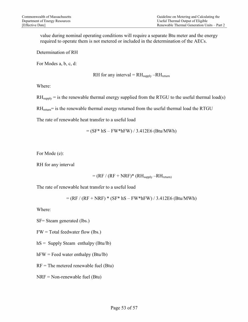
Commonwealth of Massachusetts Guideline on Metering and Calculating the
Department of Energy Resources Useful Thermal Output of Eligible
[Effective Date] Renewable Thermal Generation Units – Part 2
Page 53 of 57
value during nominal operating conditions will require a separate Btu meter and the energy
required to operate them is not metered or included in the determination of the AECs.
Determination of RH
For Modes a, b, c, d:
RH for any interval = RHsupply –RHreturn
Where:
RHsupply = is the renewable thermal energy supplied from the RTGU to the useful thermal load(s)
RHreturn= is the renewable thermal energy returned from the useful thermal load the RTGU
The rate of renewable heat transfer to a useful load
= (SF* hS – FW*hFW) / 3.412E6 (Btu/MWh)
For Mode (e):
RH for any interval
= (RF / (RF + NRF)* (RHsupply –RHreturn)
The rate of renewable heat transfer to a useful load
= (RF / (RF + NRF) * (SF* hS – FW*hFW) / 3.412E6 (Btu/MWh)
Where:
SF= Steam generated (lbs.)
FW = Total feedwater flow (lbs.)
hS = Supply Steam enthalpy (Btu/lb)
hFW = Feed water enthalpy (Btu/lb)
RF = The metered renewable fuel (Btu)
NRF = Non-renewable fuel (Btu)

Commonwealth of Massachusetts Guideline on Metering and Calculating the
Department of Energy Resources Useful Thermal Output of Eligible
[Effective Date] Renewable Thermal Generation Units – Part 2
Page 54 of 57
H) Compost Vapor Heat Recovery RTGUs
1) Major Components
The major components of a Compost Vapor Heat Recovery RTGU are:
(a) Vapor to water heat exchanger(s)
(b) Pumps, piping, fittings which interconnect connect the RTGU with the facility thermal
distribution system and allow the transfer of thermal energy from the generation system
to the facility thermal loads.
(c) Condensate return system
(d) Systems to reject excess heat
(e) System controls
(f) Data acquisition and plant historian systems
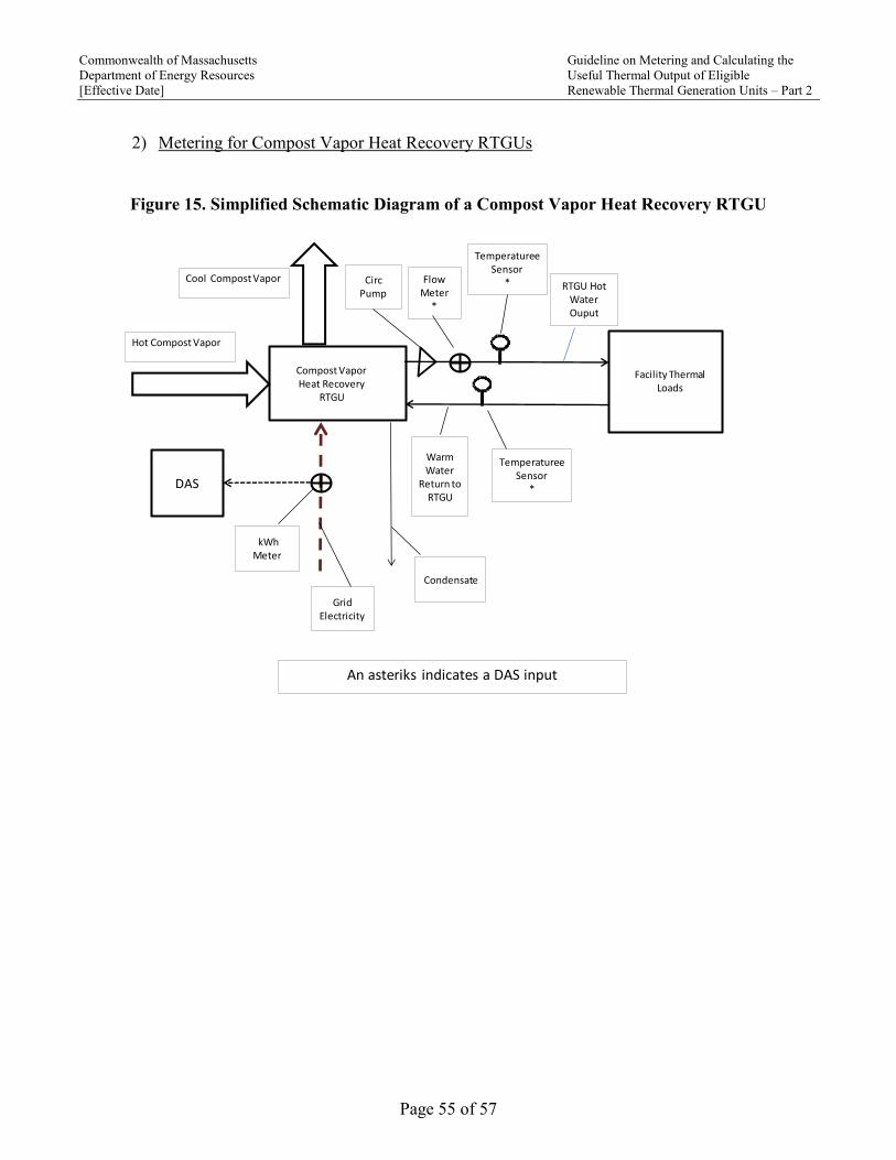
Commonwealth of Massachusetts Guideline on Metering and Calculating the
Department of Energy Resources Useful Thermal Output of Eligible
[Effective Date] Renewable Thermal Generation Units – Part 2
Page 55 of 57
2) Metering for Compost Vapor Heat Recovery RTGUs
Figure 15. Simplified Schematic Diagram of a Compost Vapor Heat Recovery RTGU
`
Compost Vapor Heat Recovery
RTGU
Hot Compost Vapor
Facility Thermal Loads
RTGU Hot Water Ouput
WarmWater
Return to RTGU
CircPump
Cool Compost Vapor
kWh Meter
Condensate
TemperatureeSensor
*
TemperatureeSensor
*
Flow Meter
*
DAS
Grid Electricity
An asteriks indicates a DAS input

Commonwealth of Massachusetts Guideline on Metering and Calculating the
Department of Energy Resources Useful Thermal Output of Eligible
[Effective Date] Renewable Thermal Generation Units – Part 2
Page 56 of 57
3) Formula for Compost Vapor Recovery RTGUs
E net, out = (RH −NUH −G/0.44)
and
AECs = E net, out * M
Where:
E net, out = Net thermal energy output equivalent
RH = Renewable heat transferred to the useful loads
NUH = Any heat generated by the RTGU that is transferred to a non-useful load such as heat
rejected by an over temperature protection system.
M = The appropriate multiplier as defined in the Department’s Guideline on Multipliers for
Renewable Thermal Generation Units
Determination of RH:
RH for any interval = RHsupply –RHreturn
Where:
RHsupply = is the renewable thermal energy supplied from the RTGU to the useful thermal load(s)
RHreturn= is the renewable thermal energy returned from the useful thermal load the RTGU
The renewable heat transfer to a useful load over an interval:
= (GWSF * Cp * (CWST – CWRT) / 3.412E6 (Btu/MWh)
Where:
GWSF = Ground water supply flow (lbs)
Cp = Specific heat of the circulating loop fluid (Btu/lb-°F)
CWST = Circulating hot water supply temperature to the useful load (°F)

Commonwealth of Massachusetts Guideline on Metering and Calculating the
Department of Energy Resources Useful Thermal Output of Eligible
[Effective Date] Renewable Thermal Generation Units – Part 2
Page 57 of 57
CWRT = Circulating water return temperature from the useful load (°F)
G = Grid supplied electrical energy
Conversion of site to source nonrenewable fuel per MWh grid electricity= G / (0.44)
4) Miscellaneous
The Department may permit an exception from any provision of this Guideline for good cause, so
long as the exception is consistent with the requirements set out in G.L. c. 25A, § 11F ½ and
regulations promulgated thereunder.