Embed Size (px)
Citation preview

04 December 2009
Guideline for tyre labeling to promote the use of
fuel efficient tyres (labeling system)
Japan Automobile Tyre Manufacturers Association, Inc.
The purpose of this guideline is to establish: a tyre grading system that is based on
both the tyre RR and Wet Grip performance; a definition of the fuel efficient tyre that
complies with a certain level of tyre RR and Wet Grip performance; and a labeling
system that provides appropriate information on tyres to the consumer as an
implementation program of the fuel efficient tyre use promotion which is framed by
the Fuel-Efficient Tire Promotion Council. (Chairman: Mr. Yasuhiro Daisho,)
1. Scope
This guideline applies to summer-use tyres for passenger vehicles that are
purchased as replacement tyres by consumers at a tyre dealer etc.
2. Terms and Definitions
1) Fuel efficient tyres
A tyre with an RRC that is not more than the RRC specified in section 4 and
which has an adequate performance level from a safety standpoint.
2) Rolling Resistance (RR)
Loss of energy (or energy consumed) per unit of distance traveled.
Note: The International System of Units (SI) unit conventionally used for the rolling resistance is “N・m/m”,
which is equivalent to a drag force in “N”.
3) Rolling Resistance Coefficient (RRC)
Ratio of the rolling resistance to the load on the tyre.
Note: The rolling resistance is expressed in “N” and the load is expressed in “kN”. The rolling resistance
coefficient is dimensionless.
4) Wet Grip performance
Grip performance of tyres on a wet-paved surface. (Grip performance when
braking, etc.)
1/5

5) RRC alignment (alignment between test machines) method
A method for correlating RRC measurement results which allows for
inter-laboratory comparisons between the reference machine and candidate
machine(s) using two predetermined alignment tyres.
6) Alignment tyres
Two predetermined tyres measured by both the candidate and reference
machines to perform machine alignment.
7) Reference tyre for Wet Grip performance test
Special test tyre used as a benchmark in an evaluation program to correct
impacts on measuring data caused by differences in road characteristics and
testing environments.
3. Grading system
The tyre grading system shall be as follows:
Unit(N/kN) Unit(%)
RRC Grade Wet Grip performance (G) Grade
RRC≦6.5 AAA 155≦G a
6.6≦RRC≦7.7 AA 140≦G≦154 b
7.8≦RRC≦9.0 A 125≦G≦139 c
9.1≦RRC≦10.5 B 110≦G≦124 d
10.6≦RRC≦12.0 C
4. Performance requirements for fuel efficient tyres
RRC: Not more than 9.0
Wet Grip performance shall be within the grading system stipulated in section 3.
5. Labeling method (Display)
The grading system prescribed in section 3 shall be disclosed to the consumer
upon the sale of the tyres and, at the same time, the grades of the tyres shall be
published in catalogs, on web pages etc. by the format (draft) shown below.
In addition, for fuel efficient tyres that meet the requirements specified in section
4, “the unified fuel efficient tyre mark” shall also be indicated on the label.
Labeling cannot be applied to tyres which do not satisfy the RRC or Wet Grip
grades of the grading system specified in section 3.
2/5

【Examples of display】
Fuel efficient tyre
Non fuel efficient tyre
【Meaning of marks】
・・・Standardized mark for fuel efficient tyres
・・・Rolling Resistance performance
・・・Wet grip performance
6. Test method
1) For RRC, JIS D4234: 2009 (ISO28580), Passenger car, truck and bus tyres -
Methods of measuring rolling resistance - Single point test and correlation of
measurement results, shall be applied.
2) For Wet Grip performance, Annex 1 of EU regulation Wet Grip grading test
method (draft) – “Test method for tyre Wet Grip grading (C1 tyres)” shall be
applied.
3/5

7. Application Period
The provision of consumer information regarding the labeling system based on
this guideline shall be applied to tyres by each manufacturer. The application shall
begin from January 2010 in voluntary stages and shall be completed by December
2011. Completion shall be by December 2010 for fuel efficient tyres.
8. Others
1) Credibility
a) Management of RR test facilities
The quality management standard of ISO/TS16969 (regulation to
standardize the quality management system for automobiles and automobile
parts) or ISO17025 (JIS Q17025: general requirements for the ability of
testing and calibration laboratories/facilities) shall be applied.
b) Alignment method of RRC
For the time being, the alignment of measured RRC shall be conducted by
the RRC alignment method with the reference test machine selected from
the JATMA members listed in Appendix 2.
c) Wet Grip performance
Wet Grip performance shall be measured based on Appendix 1: EU
regulation Wet Grip grading test method (draft) (test method for tyre Wet
Grip grading (C1 tyres)) and an index for the Wet Grip performance shall be
calculated according to comparisons of the reference tyre.
d) Submission of data
Each tyre manufacturer shall submit its data as evidence to the Tire Fair
Trade Council in accordance with The Fair Competition Code and The
Enforcement Rules of the Fair Competition established by the Tire Fair
Trade Council and based on the Act against Unjustifiable Premiums and
Misleading Representations.
2) How to inform consumers
Educate consumers about fuel efficient tyres, grading definitions and the
contents of the grading display through manufacturer product catalogs, web
pages and the labels attached to tyres.
4/5

5/5
3) Revision and amendment of the guideline
Revised and amended as necessary while taking into consideration consumer
awareness of fuel efficient tyres, advances in technology and adjustment
conversions of other countries.

ETRTO Wet Grip Grading Test Method for C1 tyres – editorial correction, 22nd July 2009
Page 1/16
T E S T M E T H O D F O R T Y R E W E T G R I P G R A D I N G ( C 1 T Y R E S )
1 . SCOPE
This test applies to C1 tyres and specifies the method for measuring relative wet grip braking performance index to a reference under loaded conditions for new tyres for use on passenger cars on a wet-paved asphalt, for the solely purpose of applying a relative wet grip braking performance grading. The methods developed are meant to improve Reg117. The use of reference tyres (later on called SRTT16”) is necessary to limit the variability of the testing procedures.
2 . NORMATIVE REF ERENCES
The following referenced documents are indispensable for the application of this document. For dated references, only the edition cited applies. For undated references, the latest edition of the referenced document (including any amendments) applies.
ASTM E 303:1993 (re-approved in 1998), Standard Test Method for Measuring Surface Frictional Properties Using the British Pendulum Tester
ASTM E 501, Standard Specification for Standard Rib Tire for Pavement Skid-Resistance Tests
ASTM E 965, Standard Test Method for Measuring Pavement Macrotexture Depth Using a Volumetric Technique
ASTM E 1136, Standard Specification for a Radial Standard Reference Test Tire (SRTT14”)
ASTM F 2493, Standard Specification for a Radial Standard Reference Test Tire (SRTT16”)
3 . TERMS AND DEF INIT IONS
For the solely purposes of this test, the following terms and definitions apply:
3.1 test run: single pass of a loaded tyre over a given test surface
3.2 candidate tyre T (set): test tyre (set) that is part of an evaluation programme; the brand name, the trade description or the trade mark.
3.3 reference tyre R (set): special test tyre (set) that is used as a benchmark in an evaluation programme (SRTT16”) NOTE These tyres usually have carefully controlled design features to minimize variation.
3.4 control tyre (set): tyre (set) that is part of an evaluation programme; it is an intermediate tyre (set) which is used when the candidate tyre and the reference tyre cannot be directly compared on the same vehicle
3.5 braking force of a tyre: longitudinal force, expressed in newtons, resulting from braking torque application
3.6 braking force coefficient of a tyre BFC: ratio of braking force to vertical load
3.7 peak braking force coefficient of a tyre: maximum value of tyre braking force coefficient that occurs prior to wheel lockup as the braking torque is progressively increased
3.8 lockup of a wheel: condition of a wheel in which its rotational velocity about the wheel spin axis is zero and it is prevented from rotating in the presence of applied wheel torque
3.9 vertical load: normal reaction of the tyre on the road
3.10 tyre test vehicle: dedicated special purpose vehicle which has instruments to measure the vertical and the longitudinal forces on one tyre during braking
Attachment 1

ETRTO Wet Grip Grading Test Method for C1 tyres – editorial correction, 22nd July 2009
Page 2/16
4 . MET HODS FOR MEASURING W ET GRIP
Relative wet grip braking performance for loaded passenger car new tyres travelling straight ahead on a wet, paved surface can be measured by one of the following methods:
- vehicle method consisting of testing a set of tyres mounted on a standard vehicle;
- test method using a trailer or a tyre test vehicle equipped with the test tyres.
5 . GENERAL T EST CONDIT IONS 5.1 Track characteristics
The surface shall have a dense asphalt surface with a uniform gradient of not more than 2 % and shall not deviate more than 6 mm when tested with a 3 m straight edge.
The test surface shall have a pavement of uniform age, composition, and wear. The test surface shall be free of loose material and foreign deposits.
The maximum chipping size shall be from 8 mm to 13 mm.
The sand depth measured as specified in ASTM E 965 shall be (0,7 ± 0,3) mm.
In order to verify the wetted frictional properties of the surface, either method a) or b) shall be used.
a) British Pendulum Number (BPN) method
The averaged British Pendulum Number (BPN) (British Pendulum Tester method as specified in ASTM E 303 using the pad as specified in ASTM E 501) shall belong to (42 to 60) BPN range after temperature correction.
Pad rubber component formulation and physical properties are to be requested.
BPN shall be corrected by the wetted road surface temperature. Unless temperature correction recommendations are indicated by the British pendulum manufacturer, the following formula can be used:
BPN=BPN(measured value) + temperature correction
temperature correction = −0,001 8 t 2 + 0,34 t − 6,1
where t is the wetted road surface temperature in degrees Celsius.
Effects of slider pad wear: The pad shall be removed for maximum wear when the wear on the striking edge of the slider reaches 3,2 mm in the plane of the slider or 1,6 mm vertical to it in accordance with ASTM E 303:1993, 5.2.2 and Figure 3.
Checking track surface BPN consistency for the measurement of wet grip on a standard vehicle: To decrease the dispersion of test results, the BPN values of the track should not vary over the entire stopping distance. The operation shall be repeated five times at each point of the BPN measurement. Measurements shall be taken every 10 m on the braking lane and the coefficient of variation of the BPN averages shall not exceed 10 %.
b) ASTM E 1136 Standard Reference Test Tyre (SRTT14”) method
The average peak braking coefficient (µpeak,ave) of the ASTM E 1136 SRTT14” 1) (see Chapt 7) shall be 0,7 ± 0,1 at 65 km/h.
For the trailer method, testing is run in such a way that braking occurs within 2 m of where the surface was examined.
The average peak braking coefficient (µpeak,ave) of the ASTM E 1136 SRTT14” shall be corrected by the wetted road surface temperature:
peak braking coefficient (µpeak,ave)= peak braking coefficient (measured) + temperature correction
temperature correction = 0,0035 x (t − 20)
where t is the wetted road surface temperature in degrees Celsius.
1 The size of the ASTM E 1136 SRTT is P195/75R14.

ETRTO Wet Grip Grading Test Method for C1 tyres – editorial correction, 22nd July 2009
Page 3/16
5.2 Wetting conditions
The surface may be wetted from the track-side or by a wetting system incorporated in the test vehicle or the
trailer.
If “external watering” is used, water the test surface at least half an hour prior to testing in order to equalize
the surface temperature and water temperature. External watering should be supplied continuously throughout
testing.
For the whole testing area, the water depth shall be between 1.0 ± 0.5 mm.
5.3 Atmospheric conditions
The wind conditions shall not interfere with wetting of the surface (wind-shields are allowed).
Both the wetted surface temperature and the ambient temperature shall be between:
2 °C and 20 °C for the snow tyres
5°C and 35 °C for the normal tyres
Moreover, the wetted surface temperature shall not vary during the test by more than 10 °C.
The ambient temperature must remain close to the wetted surface temperature; the difference between the ambient and the wetted surface temperatures must be less than 10°C.
5.4 Reference tyre (SRTT16”)
The specifications of the Standard Reference Testing Tyre to be used during the test (SRTT16”) are defined in ASTM F 2493.
6 . MEASUREMENT OF TYRE WET GRIP ON A STANDARD VEHICL E
6.1 Principle
The test method covers a procedure for measuring the deceleration performance of passenger car tyres
during braking, using an instrumented passenger car having an Antilock Braking System (ABS).
Starting with a defined initial speed, the brakes are applied hard enough on four wheels at the same time to
activate the ABS. The average deceleration is calculated between two defined speeds, with an initial speed of
80 km/h and a final speed of 20 km/h. When the braking system is not operating automatically, a minimum of
600 N pedal effort is required.
6.2 Equipment
6.2.1 Vehicle
Permitted modifications using a standard-model passenger car equipped with an ABS are as follows:
• those allowing the number of tyre sizes that can be mounted on the vehicle to be increased;
• those permitting automatic activation of the braking device to be installed.
Any other modification of the braking system is prohibited.
6.2.2 Measuring equipment
The vehicle shall be fitted with a sensor suitable for measuring speed on a wet surface and distance covered
between two speeds.
To measure vehicle speed, a fifth wheel or non-contact speed-measuring system should be used.
ETRTO Wet Grip Grading Test Method for C1 tyres – editorial correction, 22nd July 2009
Page 4/16
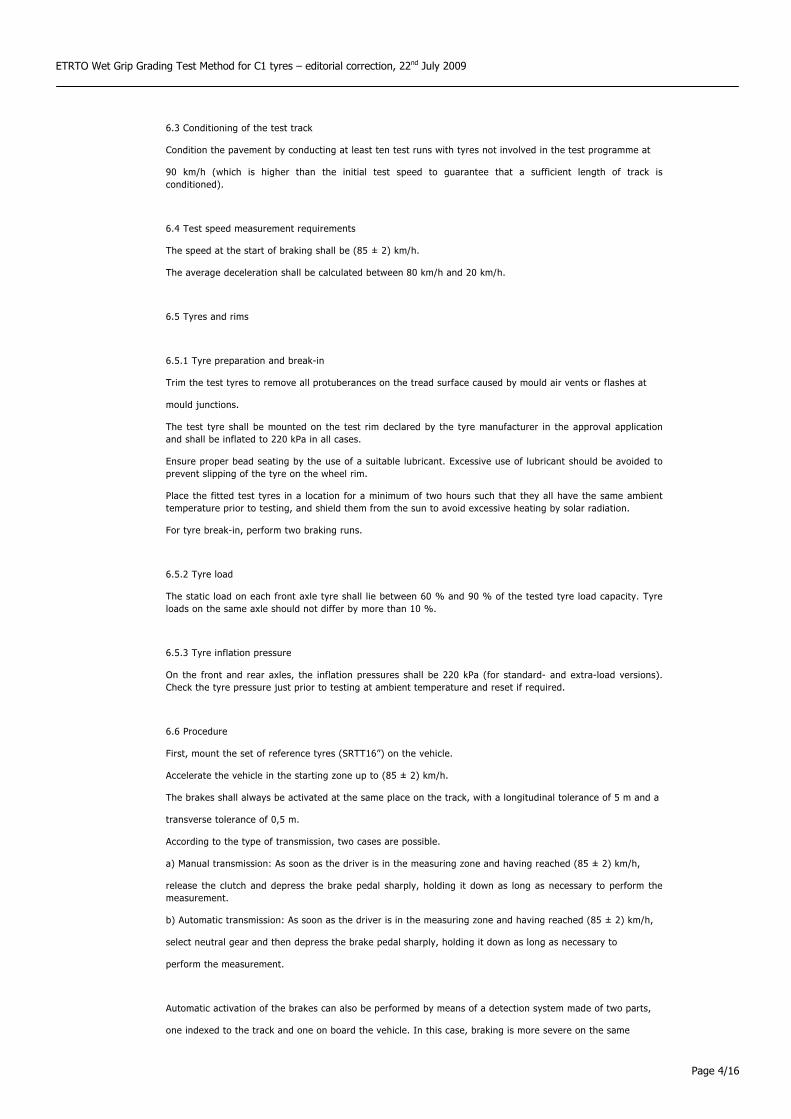
6.3 Conditioning of the test track
Condition the pavement by conducting at least ten test runs with tyres not involved in the test programme at
90 km/h (which is higher than the initial test speed to guarantee that a sufficient length of track is conditioned).
6.4 Test speed measurement requirements
The speed at the start of braking shall be (85 ± 2) km/h.
The average deceleration shall be calculated between 80 km/h and 20 km/h.
6.5 Tyres and rims
6.5.1 Tyre preparation and break-in
Trim the test tyres to remove all protuberances on the tread surface caused by mould air vents or flashes at
mould junctions.
The test tyre shall be mounted on the test rim declared by the tyre manufacturer in the approval application and shall be inflated to 220 kPa in all cases.
Ensure proper bead seating by the use of a suitable lubricant. Excessive use of lubricant should be avoided to prevent slipping of the tyre on the wheel rim.
Place the fitted test tyres in a location for a minimum of two hours such that they all have the same ambient temperature prior to testing, and shield them from the sun to avoid excessive heating by solar radiation.
For tyre break-in, perform two braking runs.
6.5.2 Tyre load
The static load on each front axle tyre shall lie between 60 % and 90 % of the tested tyre load capacity. Tyre loads on the same axle should not differ by more than 10 %.
6.5.3 Tyre inflation pressure
On the front and rear axles, the inflation pressures shall be 220 kPa (for standard- and extra-load versions). Check the tyre pressure just prior to testing at ambient temperature and reset if required.
6.6 Procedure
First, mount the set of reference tyres (SRTT16”) on the vehicle.
Accelerate the vehicle in the starting zone up to (85 ± 2) km/h.
The brakes shall always be activated at the same place on the track, with a longitudinal tolerance of 5 m and a
transverse tolerance of 0,5 m.
According to the type of transmission, two cases are possible.
a) Manual transmission: As soon as the driver is in the measuring zone and having reached (85 ± 2) km/h,
release the clutch and depress the brake pedal sharply, holding it down as long as necessary to perform the measurement.
b) Automatic transmission: As soon as the driver is in the measuring zone and having reached (85 ± 2) km/h,
select neutral gear and then depress the brake pedal sharply, holding it down as long as necessary to
perform the measurement.
Automatic activation of the brakes can also be performed by means of a detection system made of two parts,
one indexed to the track and one on board the vehicle. In this case, braking is more severe on the same

ETRTO Wet Grip Grading Test Method for C1 tyres – editorial correction, 22nd July 2009
Page 5/16
portion of the track.
If any of the above-mentioned conditions is not met when a measurement is made (speed tolerance, braking
time, etc.), the measurement is discarded and a new measurement is made.
For each test and for new tyres, the first two braking measurements are discarded.
After at least three valid measurements have been made, the reference tyres (SRTT16”) are replaced by a set of the candidate tyres and at least six valid measurements shall be performed making runs in the same direction.
Every test must be closed with reference tyre (SRTT16”) re-test.
A maximum of three sets of candidate tyres can be tested before the reference (SRTT16”) tyre is re-tested.
EXAMPLES
The run order for a test of three sets of candidate tyres (T1 to T3) plus a reference tyre R would be the following:
R-T1-T2-T3-R
The run order for a test of five sets of candidate tyres (T1 to T5) plus a reference tyre R would be the following:
R-T1-T2-T3-R-T4-T5-R
6.7 Processing of measurement results
6.7.1 Calculation of the average deceleration, AD
Each time the measurement is repeated, the average deceleration, AD (m·s−2), is calculated by
dSS
AD if
2
22 −=
where
Sf is the final speed (m·s−1);
Si is the initial speed (m·s−1);
d is the distance covered (m) between Si and the Sf.
6.7.2 Validation of results
For the reference tyre (SRTT16”): If the AD “coefficient of variation” of any two consecutive groups of three runs of the reference tyre is higher than 3 %, discard all data and repeat the test for all tyres (the candidate tyres and the reference tyre).

ETRTO Wet Grip Grading Test Method for C1 tyres – editorial correction, 22nd July 2009
Page 6/16
The coefficient of variation is calculated by the following relation:
100average
deviation standard×
For the candidate tyres: The coefficients of variation 100average
deviation standard× are calculated for all the
candidate tyres. If one coefficient of variation is greater than 3 %, discard the data for this candidate tyre and
repeat the test.
6.7.3 Calculation of average AD
If R1 is the average of the AD values in the first test of the reference tyre and R2 is the average of the AD
values in the second test of the reference tyre, the following operations are performed, according to Table 1.
Ra is the adjusted average AD of the reference tyre (SRTT16”) (m·s−2).
Table 1
Number of sets of candidate
tyres between two successive
runs of the reference tyre
Set of candidate tyres to be
Qualified Ra
1 R-T1-R T1 Ra = 1/2 (R1 + R2)
2 R-T1-T2-R T1
T2
Ra = 2/3 R1 + 1/3 R2
Ra = 1/3 R1 + 2/3 R2
3 R-T1-T2-T3-R
T1
T2
T3
Ra = 3/4 R1 + 1/4 R2
Ra = 1/2 (R1 + R2)
Ra = 1/4 R1 + 3/4 R2
Ta (a = 1, 2, etc.) is the average of the AD values for a test of a candidate tyre.
6.7.4 Calculation of braking force coefficient, BFC
BFC(R) and BFC(T) are calculated according to Table 2.
Table 2
Tyre type Braking force coefficient,
for a braking on the two axles
Reference tyre (SRTT16”) g
RaRBFC =)(
Candidate tyre BFC(T)= Ta/g
g is the acceleration due to gravity (rounded to 9,81 m·s−2).

ETRTO Wet Grip Grading Test Method for C1 tyres – editorial correction, 22nd July 2009
Page 7/16
6.7.5 Calculation of the relative wet grip performance index of the tyre
The wet grip index of the tyre is calculated by the formula
⎟⎟⎠
⎞⎜⎜⎝
⎛−×+×+×= 0.1
)()()t-(ta125
)()()(
00 RBFC
RBFCbRBFCTBFCTIndexGripWet
which represents the relative wet grip performance index of the candidate tyre compared to the reference tyre (SRTT16”) and where
t is the measured wet surface temperature in degree Celsius when the candidate “T” tyre is tested t0 is the wet surface reference temperature condition t0=20°C for normal tyres t0=10°C for snow tyres BFC(R0) = 0.68 is the breaking force coefficient for the SRTT16” in the reference conditions a= -0.4232 & b = -8.297 for Normal tyres a = 0.7721 & b = 31.18 for Snow tyres
6.8 Wet grip performance comparison between a candidate tyre and a reference tyre (SRTT16”) using a control tyre
6.8.1 General
When the candidate tyre size is significantly different from that of the reference tyre, a direct comparison on
the same vehicle may be not possible. This approach uses an intermediate tyre, hereinafter called the control
tyre.
6.8.2 Principle of the approach
The principle is the use of a control tyre and two different vehicles for the assessment of a candidate tyre in
comparison with a reference tyre.
One vehicle can be fitted with the reference tyre and the control tyre, the other with the control tyre and the
candidate tyre. All conditions are in conformity with 6.2 to 6.5.
The first assessment is a comparison between the control tyre and the reference tyre.
The second assessment is a comparison between the candidate tyre and the control tyre.
The second assessment is done on the same track as the first assessment. The wetted surface temperature shall be within ± 5 °C of the temperature of the first assessment. The control tyre set (four tyres) are physically the same set as was used for the first assessment.
The wet grip performance index of the candidate tyre compared to the reference tyre is deduced by multiplying the relative efficiencies calculated above:
wet grip index 1 × wet grip index 2 × 10⁻²
where
wet grip index 1 is the relative efficiency of the control tyre compared to the reference tyre (SRTT16”);
wet grip index 2 is the relative efficiency of the candidate tyre compared to the control tyre.

ETRTO Wet Grip Grading Test Method for C1 tyres – editorial correction, 22nd July 2009
Page 8/16
6.8.3 Selection of a control tyre set
A control tyre set is a group of four identical tyres made in the same factory during a one-week period.
6.8.4 Storage and preservation
Before the first assessment (control tyre/reference tyre), normal storage conditions can be used. It is
necessary that all the tyres of a control tyre set have been stored in the same conditions.
As soon as the control tyre set has been assessed in comparison with the reference tyre, specific storage
conditions shall be applied (as requested by ASTM E 1136).
6.8.5 Replacement of reference tyres and control tyres
When irregular wear or damage results from tests, or when wear influences the test results, the use of the tyre
shall be discontinued.

ETRTO Wet Grip Grading Test Method for C1 tyres – editorial correction, 22nd July 2009
Page 9/16
7 . TEST METHOD USING A TRAIL ER OR A TYRE TEST VEHI CLE
7.1 Principle
The measurements are conducted on tyres mounted on a trailer towed by a vehicle or a tyre test vehicle. The
brake in the test position is applied firmly until sufficient braking torque is generated to produce the maximum
braking force that will occur prior to wheel lockup at a test speed of 65 km/h.
7.2 Test apparatus
7.2.1 The test apparatus consists of tow vehicle and trailer or a tyre test vehicle.
7.2.1.1 The test apparatus shall have the capability of maintaining the specified speed, (65 ± 2) km/h,
even under the maximum braking forces.
7.2.1.2 The test apparatus shall be equipped with one test position and the following accessories:
• equipment to actuate brakes in the test position;
• a water tank to store sufficient water to supply the watering system, unless external watering is used;
• recording equipment to record signals from transducers installed at the test position and to monitor water application rate if the self-watering option is used.
In the case of the trailer, the longitudinal distance from the centre line of the articulation point of the coupling
to the transverse centre line of the axle of the trailer shall be at least ten times the “hitch height” or the
“coupling (hitch) height”.
7.2.1.3 The limiting change of toe and camber for the test position shall be within ± 0,5° with maximum
vertical load. Suspension arms and bushings shall have sufficient rigidity necessary to minimize free play and
ensure compliance under application of maximum braking forces. The suspension system shall provide
adequate load-carrying capacity and be of such a design as to isolate suspension resonance.
7.2.1.4 The test position shall be equipped with a typical or special automotive brake system
which can apply sufficient braking torque to produce the maximum value of braking test wheel longitudinal
force at the conditions specified.
7.2.1.5 The brake application system shall be able to control the time interval between initial brake application and peak longitudinal force as specified in 7.4.3.2.
7.2.1.6 The test apparatus shall be designed to accommodate the range of passenger car tyre sizes to
be tested.
7.2.1.7 The test apparatus shall have provisions for adjustment of vertical load as specified in 7.5.

ETRTO Wet Grip Grading Test Method for C1 tyres – editorial correction, 22nd July 2009
Page 10/16
7.2.2 The apparatus may be optionally equipped with a pavement-wetting system, less the storage tank,
which, in the case of the trailer, is mounted on the tow vehicle. The water being applied to the pavement
ahead of the test tyres shall be supplied by a nozzle suitably designed to ensure that the water layer
encountered by the test tyre has a uniform cross section at the test speed with a minimum splash and overspray.
The nozzle configuration and position shall ensure that the water jets are directed towards the test tyre and pointed towards the pavement at an angle of 20° to 30°.
The water shall strike the pavement 0,25 m to 0,45 m ahead of the centre of tyre contact. The nozzle shall be located 25 mm above the pavement or at the minimum height required to clear obstacles which the tester is expected to encounter, but in no case more than 100 mm above the pavement.
The water layer shall be at least 25 mm wider than the test tyre tread and applied so the tyre is centrally located between the edges. Water delivery rate shall ensure a water depth of 1.0 ± 0.5 mm and shall be consistent throughout the test to within ± 10 per cent. The volume of water per unit of wetted width shall be
directly proportional to the test speed. The quantity of water applied at 65 km/h shall be 18 l·s−1 per meter of width of wetted surface in case of a water depth of 1.0 mm.
7.2.3 Instrumentation
The test wheel position on the trailer or the tyre test vehicle shall be equipped with a rotational wheel velocity measuring system and with transducers to measure the braking force and vertical load at the test wheel.
7.2.3.1 General requirements for measurement system
The instrumentation system shall conform to the following overall requirements at ambient temperatures
between 0 °C and 45 °C:
• overall system accuracy, force: ± 1,5 % of the full scale of the vertical load or braking force;
• overall system accuracy, speed: ± 1,5 % of speed or ± 1,0 km/h, whichever is greater;
7.2.3.2 Vehicle speed
To measure vehicle speed, a fifth wheel or non-contact precision speed-measuring system should be used.
7.2.3.3 Braking forces
The braking force-measuring transducers shall measure longitudinal force generated at the tyre–road
interface as a result of brake application within a range from 0 % to at least 125 % of the applied vertical load.
The transducer design and location shall minimize inertial effects and vibration-induced mechanical resonance.
7.2.3.4 Vertical load
The vertical load-measuring transducer shall measure the vertical load at the test position during brake
application. The transducer shall have the same specifications as described previously.

ETRTO Wet Grip Grading Test Method for C1 tyres – editorial correction, 22nd July 2009
Page 11/16
7.2.3.5 Signal conditioning and recording system
All signal conditioning and recording equipment shall provide linear output with necessary gain and data
reading resolution to meet the specified previous requirements. In addition, the following requirements apply.
• The minimum frequency response shall be flat from 0 Hz to 50 Hz (100 Hz) within ± 1 % full scale.
• The signal-to-noise ratio shall be at least 20/1.
• The gain shall be sufficient to permit full-scale display for full-scale input signal level.
• The input impedance shall be at least ten times larger than the output impedance of the signal source.
• The equipment shall be insensitive to vibrations, acceleration, and changes in ambient temperature.
7.3 Selection and preparation of test tyres
7.3.1 Trim the test tyres to remove all protuberances on the tread surface caused by mould air vents or
flashes at mould junctions.
7.3.2 The test tyre shall be mounted on the test rim declared by the tyre manufacturer in the approval application. Ensure proper bead seating by the use of a suitable lubricant. Excessive use of lubricant should be avoided to prevent slipping of the tyre on the wheel rim.
7.3.3 For tyre break-in, perform two braking runs.
7.3.4 Place the fitted test tyres in a location for a minimum of two hours such that they all have the same ambient temperature prior to testing and shield them from the sun to avoid excessive heating by solar radiation.
7.3.5 Check the test tyres for the specified inflation pressure at ambient temperature (cold), just prior to testing and reset if required.
The testing tyre cold inflation pressure used shall be 180 kPa for standard-load versions. For extra-load tyres, the cold inflation pressure shall be 220 kPa.
NOTE: Two pressure values are needed for the trailer, since the load on the tyre is 75 % of its load capacity (see §7.5).
7.3.6 One set of tyres shall be of the ASTM F 2493 SRTT16” type.
7.4 Preparation of apparatus and test track
7.4.1 Towed trailer
7.4.1.1 Install the test tyre on the measuring device.
7.4.1.2 Load each of the wheels to the specified test load.
ETRTO Wet Grip Grading Test Method for C1 tyres – editorial correction, 22nd July 2009
Page 12/16
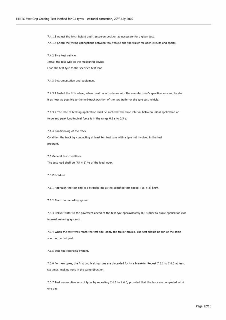
7.4.1.3 Adjust the hitch height and transverse position as necessary for a given test.
7.4.1.4 Check the wiring connections between tow vehicle and the trailer for open circuits and shorts.
7.4.2 Tyre test vehicle
Install the test tyre on the measuring device.
Load the test tyre to the specified test load.
7.4.3 Instrumentation and equipment
7.4.3.1 Install the fifth wheel, when used, in accordance with the manufacturer’s specifications and locate
it as near as possible to the mid-track position of the tow trailer or the tyre test vehicle.
7.4.3.2 The rate of braking application shall be such that the time interval between initial application of
force and peak longitudinal force is in the range 0,2 s to 0,5 s.
7.4.4 Conditioning of the track
Condition the track by conducting at least ten test runs with a tyre not involved in the test
program.
7.5 General test conditions
The test load shall be (75 ± 5) % of the load index.
7.6 Procedure
7.6.1 Approach the test site in a straight line at the specified test speed, (65 ± 2) km/h.
7.6.2 Start the recording system.
7.6.3 Deliver water to the pavement ahead of the test tyre approximately 0,5 s prior to brake application (for
internal watering system).
7.6.4 When the test tyres reach the test site, apply the trailer brakes. The test should be run at the same
spot on the test pad.
7.6.5 Stop the recording system.
7.6.6 For new tyres, the first two braking runs are discarded for tyre break-in. Repeat 7.6.1 to 7.6.5 at least
six times, making runs in the same direction.
7.6.7 Test consecutive sets of tyres by repeating 7.6.1 to 7.6.6, provided that the tests are completed within
one day.

ETRTO Wet Grip Grading Test Method for C1 tyres – editorial correction, 22nd July 2009
Page 13/16
7.6.8 Test the reference tyre (SRTT16”) adjacent to each set of test tyres, for example in the sequence
R-T1-T2-R-T3-T4-R, etc., where R is the reference tyre (SRTT16”) and Tn (where n = 1, 2, etc.) is the test tyre.
A maximum of three sets of candidate tyres may be tested before the reference tyre is re-tested.
The examples given in 6.6 (i.e. 6.6, EXAMPLES) apply.
7.7 Processing of measurement results
7.7.1 Use the following equation for each test:
)()()(
tfvtfht =µ
where
µ(t) is the dynamic tyre braking force coefficient in real time;
fh(t) is the dynamic braking force in real time, in N;
fv(t) is the dynamic vertical load in real time, in N.
7.7.2 Using the equation given in 7.7.1, calculate the peak tyre braking force coefficient, µpeak, by
determining the highest value of µ(t) before lockup occurs. Analog signals should be filtered to remove noise.
Digitally recorded signals may be filtered using a moving average technique.
7.7.3 Calculate the average values of peak braking coefficient, µpeak,ave, by averaging the repeated runs for each set of test and reference tyres for each test condition.
7.7.4 Validation of results
For the reference tyre (SRTT16”): If the coefficient of variation of the peak braking coefficient, which is calculated by
100average
deviation standard×
of the reference tyre, is higher than 5 %, discard all data and repeat the test for all tyres (the candidate tyres and the reference tyre).
For the candidate tyres: The coefficients of variation 100average
deviation standard× are calculated for all the
candidate tyres. If one coefficient of variation is greater than 5 %, discard the data for this candidate tyre and
repeat the test.
ETRTO Wet Grip Grading Test Method for C1 tyres – editorial correction, 22nd July 2009
Page 14/16
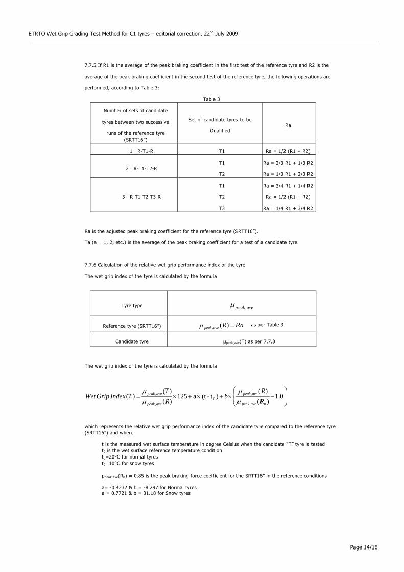
7.7.5 If R1 is the average of the peak braking coefficient in the first test of the reference tyre and R2 is the
average of the peak braking coefficient in the second test of the reference tyre, the following operations are
performed, according to Table 3:
Table 3
Number of sets of candidate
tyres between two successive
runs of the reference tyre (SRTT16”)
Set of candidate tyres to be
Qualified Ra
1 R-T1-R T1 Ra = 1/2 (R1 + R2)
2 R-T1-T2-R T1
T2
Ra = 2/3 R1 + 1/3 R2
Ra = 1/3 R1 + 2/3 R2
3 R-T1-T2-T3-R
T1
T2
T3
Ra = 3/4 R1 + 1/4 R2
Ra = 1/2 (R1 + R2)
Ra = 1/4 R1 + 3/4 R2
Ra is the adjusted peak braking coefficient for the reference tyre (SRTT16”).
Ta (a = 1, 2, etc.) is the average of the peak braking coefficient for a test of a candidate tyre.
7.7.6 Calculation of the relative wet grip performance index of the tyre
The wet grip index of the tyre is calculated by the formula
Tyre type avepeak ,µ
Reference tyre (SRTT16”) RaRavepeak =)(,µ as per Table 3
Candidate tyre µpeak,ave(T) as per 7.7.3
The wet grip index of the tyre is calculated by the formula
⎟⎟⎠
⎞⎜⎜⎝
⎛−×+×+×= 0.1
)()(
)t-(ta125)()(
)(0,
,0
,
,
RR
bRT
TIndexGripWetavepeak
avepeak
avepeak
avepeak
µµ
µµ
which represents the relative wet grip performance index of the candidate tyre compared to the reference tyre (SRTT16”) and where
t is the measured wet surface temperature in degree Celsius when the candidate “T” tyre is tested t0 is the wet surface reference temperature condition t0=20°C for normal tyres t0=10°C for snow tyres µpeak,ave(R0) = 0.85 is the peak braking force coefficient for the SRTT16” in the reference conditions a= -0.4232 & b = -8.297 for Normal tyres a = 0.7721 & b = 31.18 for Snow tyres
ETRTO Wet Grip Grading Test Method for C1 tyres – editorial correction, 22nd July 2009
Page 15/16
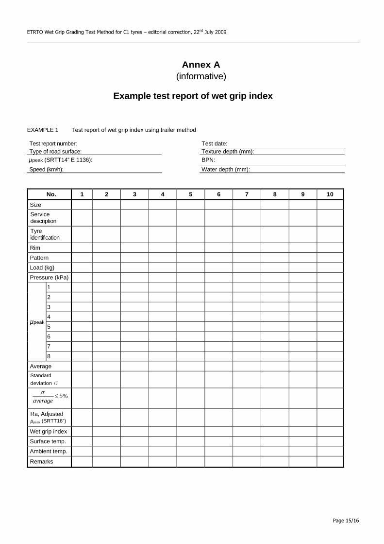
Annex A (informative)
Example test report of wet grip index
EXAMPLE 1 Test report of wet grip index using trailer method
Test report number: Test date: Type of road surface: Texture depth (mm):
µpeak (SRTT14” E 1136): BPN: Speed (km/h): Water depth (mm):
No. 1 2 3 4 5 6 7 8 9 10
Size Service description
Tyre identification
Rim Pattern Load (kg) Pressure (kPa)
1 2 3 4 5 6 7
µpeak
8 Average Standard deviation s
%5≤average
σ
Ra, Adjusted µpeak (SRTT16”)
Wet grip index Surface temp. Ambient temp. Remarks
ETRTO Wet Grip Grading Test Method for C1 tyres – editorial correction, 22nd July 2009
Page 16/16
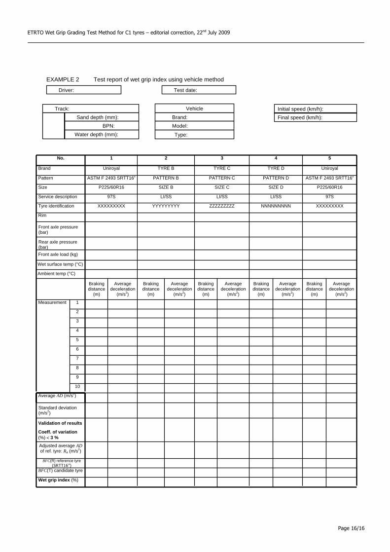
EXAMPLE 2 Test report of wet grip index using vehicle method
Sand depth (mm): BPN:
Water depth (mm):
Vehicle Brand: Model:
Type:
Track:
Driver: Test date:
No. 1 2 3 4 5
Brand Uniroyal TYRE B TYRE C TYRE D Uniroyal
Pattern ASTM F 2493 SRTT16” PATTERN B PATTERN C PATTERN D ASTM F 2493 SRTT16”
Size P225/60R16 SIZE B SIZE C SIZE D P225/60R16
Service description 97S LI/SS LI/SS LI/SS 97S
Tyre identification XXXXXXXXX YYYYYYYYY ZZZZZZZZZ NNNNNNNNN XXXXXXXXX
Rim
Front axle pressure (bar)
Rear axle pressure (bar)
Braking distance
(m)
Average deceleration
(m/s2)
Braking distance
(m)
Average deceleration
(m/s2)
Brakingdistance
(m)
Average deceleration
(m/s2)
Braking distance
(m)
Average deceleration
(m/s2)
Braking distance
(m)
Average deceleration
(m/s2)
Measurement 1
2
3
4
5
6
7
8
9
10
Average AD (m/s2)
Standard deviation (m/s2)
Validation of results
Coeff. of variation (%) < 3 %
Adjusted average AD of ref. tyre: Ra (m/s2)
BFC(R) reference tyre (SRTT16”)
BFC(T) candidate tyre
Wet grip index (%)
Front axle load (kg)
Wet surface temp (°C)
Ambient temp (°C)
Final speed (km/h): Initial speed (km/h):

xAttachment 2
The RRC alignment method
“Alignment” is a method of aligning values of rolling resistance (RR) measured by different test
methods or test machines, utilizing two predetermined tyres (alignment tyres).
Alignment is conducted using the regression formula below. The regression formula is derived
from rolling resistance coefficient (RRC) of a set of two alignment tyres, which have different RRC,
measured by both a determined reference machine and a candidate machine.
RRC Ref = An x RRC Can-n + Bn
RRC Ref : RRC value aligned with a reference machine
RRC Can-n : RRC value measured by a candidate machine-n
With this regression formula, RRC values measured by a candidate machine are aligned with
those of a reference machine.
JIS D4234 also specifies the followings:
- Conditions for the reference and candidate machines
- Alignment tyre requirements
- Alignment procedure
Correlation of RRC between the reference machine and the candidate machine
Reference Machine
Candidate Machine-1
Candidate Machine-2
Candidate Machine-3
・・・・・
RRC
Ref =
A1
×RRC
can-
1 +
B1
RRC
Ref =
A2
×RRC
can-
2 +
B2
RRC
Ref =
A3
×RRC
can-3 +
B3
RRC Ref = An x RRC Can-n + Bn
RRC Can-n
RRC
Ref
Alignment Tyre-1
Alignment Tyre-2
Reference Machine
Candidate Machine-1
Candidate Machine-2
Candidate Machine-3
・・・・・
RRC
Ref =
A1
×RRC
can-
1 +
B1
RRC
Ref =
A2
×RRC
can-
2 +
B2
RRC
Ref =
A3
×RRC
can-3 +
B3
RRC Ref = An x RRC Can-n + Bn
RRC Can-n
RRC
Ref
Alignment Tyre-1
Alignment Tyre-2