Embed Size (px)
Citation preview

1
Guideline for Procurement
of solar energy
EFFECT4buildings Toolbox:
Prosumerism; Annex 3

2
EFFECT4buildings project is implemented with the support from the EU funding Programme Interreg Baltic Sea
Region (European Regional Development Fund) and Norwegian national funding. The aim of the project is to
improve the capacity of public building managers in the Baltic Sea Region by providing them a comprehensive
decision-making support toolbox with a set of financial instruments to unlock the investments and lower the risks
of implementing energy efficiency measures in buildings owned by public stakeholders. More information:
http://www.effect4buildings.se/
Partners
The project “Effective Financing Tools for implementing Energy Efficiency in Buildings” (EFFECT4buildings)
develops in collaboration with public building managers a comprehensive decision-making support toolbox
with a set of financial instruments: Financial calculation tools; Bundling; Funding; Convincing decision
makers; Energy Performance Contract; Multi Service Contract; Green Lease Contract; Prosumerism. The
tools and instruments chosen by the project has the biggest potential to help building managers to
overcome financial barriers, based on nearly 40 interviews with the target group. The project improves
these tools through different real cases.
To make sure building managers invest in the best available solutions, more knowledge on different
possibilities is needed as well as confirmation from colleagues that the solutions performs well.
EFFECT4buildings mapped technological solutions for energy efficiency in buildings with the aim to share
knowledge and experiences of energy efficiency solutions among building managers in the Baltic Sea Region.
This document is made as manual for procurement of PV and it includes technical description guidelines.

3
EFECT4building project develop a toolbox with a set of financial instruments for building
managers to implement more energy efficiency measures. Tools belong to one or more of the
following categories: Financial calculation, Bundling, Funding, Convincing decision makers, EPC,
Multi service contracts, Green Leasing contracts and Prosumerism. This case is part of
Prosumerism.
Case owner: PP1, Dalarna County Board, Sweden
Background and motives: Building owners interest in investing in solar energy is increasing.
When investing for the first time, new knowledge is needed to make a successful installation.
The situation still prevails that the solar energy market is not yet mature, with many installers
not enough qualified to deliver a high-quality plant. These risks lead to system deficiencies and
poor performance of PV plant.
At the same time, there is not sufficient regulations in place from the different authorities. It
means that:
• regulations might be missing;
• regulations might be hard to find or understand;
• regulations might vary between municipalities, depending on different local regulations;
• local regulations might not be coordinated with other local regulations;
• situations may arise where the contractor and supplier of solar energy interpret rules
differently.
If you don’t have the right knowledge, it can be hard to procure a successful PV plant.
Purchasers seek support for how to formulate the request to solar energy installations
companies. To develop guidance and a document with proposed texts for a tendering is of
good help for building owners wanting to invest in solar energy.
Method: Based on experience from best practice cases in Ludvika municipality, Dalarna,
Sweden, this guide and tendering document has been developed.
Ludvika municipality is investing approximately 3 million Euro in solar energy for public
buildings, based on political decision.
From the initial installations valuable experiences has been gained. They have developed a
tendering document, which can now be used as a starting point for general recommendations
and advantageously by others.
Results: The result is a guide for purchasing PV systems, consisting of some overall
recommendations and a detailed text document proposal for procurement of PV systems.

4
1. GUIDE FOR PROCUREMENT OF PV Who to involve:
• Important is to bring the grid owner in the planning from the start. They have their own
rules for how the installations are to be made and after all, they are the ones who must
approve the distribution of excess electricity.
• The Fire department demand clear signs that it is a connected power installation.
Standardized rules are beginning to emerge, but so far, local rules have to be followed
in many respects, and responsible parties might not have enough knowledge and
routines either.
• Important is to have contracts with certified installers, and that they have staff with
whom it is easy to have a dialogue.
• Important is to hire a skilled inspector for final inspection of the PV-plant to check if the
plant meets all requirements.
Pre-study:
Before investing in solar energy, a pre study needs to be made of what the conditions look like
in terms of technology, economy, risk and security, which is advantageously investigated in a
feasibility study. The Solar Energy Calculation Tool, developed by the EFFECT4buildings project,
can be used in this phase.
A feasibility study should include:
• decisions on technical issues regarding the type of PV system, size and location;
• orientation of the building, available areas and potential annual production;
• electricity needs and adjustment of the size of the plant based on it.
The system requested can:
• be roof-integrated or traditional solar panels mounted on top of an existing roof;
• be thin film or silicon;
• be mono- or polycrystalline.
Investment decision
An investment needs to be presented to decision makers at one or more levels. Decision-
makers rarely have expertise in the field and the material presented should therefore be
designed in an educational way - for example, all parts of the feasibility study should be woven
together into a decision basis that is easy for managers and policy to understand and assess.
Factors that can be used as arguments for investments in solar energy:
• A contribution to a sustainable energy system;

5
Solar energy is fossil free and renewable.
• Proven technology
Solar cells are based on well-proven technology with at least 25 years warranty from the
majority of all manufacturers. Solar power can be integrated into the building's electrical
system where consumption is also done, with small transmission losses as a result.
• Low risk
The prices for electricity have fluctuated a lot. Investment in a PV plant is an insurance against
the price fluctuations over the next 25 years.
• To be a role model
Producing own electricity gives a sense of freedom, independence and pride.
Formal procurement documents (for a total responsibility from the supplier)
A request for tender contains information about the project, technical requirements for the
PV plant, criteria for the one submitting the tender, references to laws, agreements and
regulations and the division of responsibilities between the client and the contractor.
The requirements set in a procurement must be designed in a way that makes it possible to
follow up and verify that the suppliers meet them.
1 Technical description (with a pre study as an annex)
A detailed text document for technical description in a request for proposal of PV systems has
been developed.
2 Template for tendering proposal
Supplier should confirm that the products offered meet the technical requirements described
in the technical description.
The template must contain all the information that the tenderer must provide.
• Price offer (divided in to price for solar panels, inverters, mounting equipment, working
hours, eventual costs for data collection and presentation, eventual extra costs for
snow sliding fences)
• LCC analysis
• Technical data of products
o Product sheets with enough information to make it possible to evaluate
performance, reliability, personal safety, maintenance and space requirements.
o Efficiency of solar panels and inverters
o Number of solar panels and inverters

6
o Expected energy production
o Performance Ratio
o Warranties
o Planned method for mounting
• Time plan for installation

7
Technical description for procurement of photovoltaics systems
September 2019
EFFECT4buildings

8
Basics for procurement of
Photovoltaic systems
About the document
This document is a basis for procurement of photovoltaic systems for producing your own
electricity. It is based on contract documentations used in later procurement of solar energy
by Ludvika Municipality. And which have been supplemented with new experiences.
Parts of the technical description may need to be adapted to the specific procurement. This
document is adapted primarily for the procurement of traditional PV-modules. For roof
integrated solutions, certain parts of this document need to be reformulated.
The administrative regulations are not included.
Content
1 GENERAL SCOPE 9
2 QUALITY AND ENVIRONMENTAL 10
3 ELECTRICAL INSTALLATIONS 11
4 EQUIPMENT FOR ELECTRICITY PRODUCTION 13
5 MARKING, TESTING, DOCUMENTATION 17
6 AFTER FINAL INSPECTION 22

9
1. GENERAL SCOPE
1.1 PURPOSE
Overall description of which type of systems and buildings the procurement refers to.
The delivery includes installation of photovoltaic systems according to this description, to a
fully functioning and operational plant, in a turnkey contract. The delivery also includes
monitoring and being responsible for ensuring that wiring and components have the correct
function and become properly connected, within the contract. In additional to the delivery,
the contract also includes, dimensioning and design, installation and connection to the building
primary electricity system, commissioning, performance testing and service during the
warranty period.
In addition to the information stated in this description, the tenderer is required to obtain and
take into account, the necessary supplementary information about other conditions that may
exist and be of influence for the work and the costs. The contractor is not entitled to additional
compensation for work and materials not specified in the tender.
1.2. ADDITIONAL DOCUMENTS
The scope of additional documents is stated in the Administrative Regulations.
1.3. REGULATIONS
The quality of the work performed by the contractor must corresponding to the description
specified in “General material and work description AMA EL 16” even though the description
is not included in this document. All equipment must be CE marked according to regulatory
requirements. For this contract, applies the current applicable version of the Building
regulations, National Board of Housing and the Swedish Work Environment Authority
guidelines. For all laws, regulations, standards, instructions and recommendations to which
this document refers, the latest publication and any additions shall apply.
The following standards must be followed:
• National Electrical Safety Board’s regulations and general advice ELSÄK-FS 2008:1, amended by ELSÄKFS 2010:1 and ELSÄK-FS 2008:2.
• SS 436 40 00 Electrical Installations, latest edition
• SS 424 14 38 Cable management in buildings.
• SS 437 01 02 Low-voltage electrical installations - Guidelines for connection, location, metering and erection of electrical and telecommunication installations.
• SS-EN 50 160 Voltage characteristics of electricity supplied by public distribution systems.
• SS-EN 50 438 Requirements for micro-generating plants to be connected in parallel with public low-voltage distribution networks.

10
• SS-EN 60947-3 Low-voltage switchgear and controlgear - Part 3: Switches, disconnectors, switchdisconnectors and fuse-combination units.
• SS-EN 61173 Overvoltage protection for photovoltaic (PV) power generating systems.
• SS EN 61701-2 Salt mist corrosion testing of photovoltaic (PV) modules.
• SS EN 61724-1 Photovoltaic system performance - Part 1: Monitoring.
• SS EN 61727 Photovoltaic (PV) systems - Characteristics of the utility interface.
• SS EN 61727-1-2 Photovoltaic (PV) systems - Characteristics of the utility interface.
• SS EN 61853-1 Photovoltaic (PV) module performance testing and energy rating.
• SS-EN 62446-1 Photovoltaic (PV) systems - Requirements for testing, documentation and maintenance.
• IEC 61836 Solar photovoltaics energy systems -Terms and symbols
• IEC 61215 Crystalline silicon terrestrial photovoltaic (PV) modules - Design qualification and type approval.
• MSB ”Råd räddningsinsats i samband med brand i solcellsanläggning” Advice, rescue efforts in case of fire in a photovoltaics system.
• Svensk Energi ”AMP Anslutning av mindre produktionsanläggningar till elnätet - AMP (< 1 500 kW) Installationer & nätanslutning” Connection of smaller production plants to the electricity grid.
• Svensk Energi - Anslutning av mikroproduktion till konsumtionsanläggningar – MIKRO. Connection of microproduction to consumer plants – MIKRO.
• Low-voltage electrical installations SS 436 40 00 Edition 3.
• SS 430 01 01 Meter boards.
• SS 430 01 15 Meter cabinets and meter board with measuring transformer.
1.4 EXISTING CONDITIONS
The contract includes photovoltaic systems on roof. Existing conditions are described in
attached feasibility study. The feasibility study includes available roof areas, orientation and
inclination of roof. The contractor performs all piercing ang clogging. Piercing should not be
performed through the waterproofing of the roof.
2. QUALITY AND ENVIRONMENTAL Environment
Cable- and wiring system, boxes and pipes shall be UV resistant and free of bromine, lead and
halogen. PVC shall not be used.
Corrosion
For all outdoors equipment and installations in this contract applies corrosion protection class
C4. Galvanic corrosion must be taken into account when using different metals.

11
3. ELECTRICAL INSTALLATIONS
3.1. MANAGEMENT SYSTEM
All required extension of wiring between grid inverters and cabinets and other materials is
included in the contract.
Final circuit shall be protected against interference. From PV modules to grid inverters, a
double insulated, UV-resistant and multi-strand wire designed for mounting of photovoltaic
systems shall be used. The contract extends to connection to the building primary electricity
system. Wiring must be carried out, as far as possible, to prevent the risk of being damaged in
case of rescue operation, for example piercing in roof.
Wires should be visible or marked if hidden wiring needs to be carried out. DC-wires must be
labelled with safety signs, with text “Contains hazardous live parts that cannot be
disconnected”.
Passages through fire compartments with wiring duct including tubes must be sealed, by the
contractor, with approved material to maintain fire classification according to prescribed
requirements for fire compartments. Fire seals must be marked.
All wiring duct must be self-supporting.
3.2. POWER QUALITY (PQ)
The photovoltaic system must comply in full with SS-EN 50160 regarding power quality (PQ).
The client supplies power to electric panel with system voltage of 230/400 V and 50 Hz.
Placement is determined in consultation with the client.
The contract includes registration of the photovoltaics system to the owner of the electricity
grid
The installation must be designed so that stray voltage and harmonics for respective sub
system can be measured at one point. The point for measuring shall be made in special
enclosure and space shall be provide four mounting current clamps around the L1, L2, L3, N
and PE conductors. N and PE conductor must be separated from the phase conductors, so they
do not cause capacitive influence.
3.3. SITE EQUIPMENT
Site equipment shall have protection form that complies with the requirements of the space.
Electrical connections with materials that have good resistance to UV radiation, etc.
Cable ties must meet the requirements of SS-EN 62275 and be of stainless steel.
12
3.4. MEASURING EQUIPMENT
Electricity meters and data collection
The contract includes establishing a site for measuring electricity certificate. The site for
measuring must comply with Swedish standards and be designed in consultation with the
owner of the electricity grid.
An opportunity for switching must be provided on both sides of the electricity meter at the
measuring site. The owner of the electricity grid (who also reports the measurement values to
Cesar) supplies and installs the electricity meter for electricity certificate reporting and
provides meter test terminal block and current transformers to the installation company.
Loggers for collecting electrical quantities from each grid inverter in the photovoltaics system
shall be installed.
Data should be stored for a maximum of 15 minutes and historical data should be automatically
transferred for long-term storage, so no manual backup needs to be set up.
Loggers should register and collect the following values for each grid inverter:
• DC-voltage from PV array.
• DC-current from PV array.
• Momentary AC-power from grid inverters.
• Delivered electrical energy (AC) from inverters.
Loggers shall also register and collect the following quantities using sensors:
• Solar radiation should be measured by a reference cell of the same type used in
the photovoltaics system and placed with the same orientation, inclination and
shading conditions as other modules in the system.
• Air temperature should be measured through a temperature sensor protected
from direct sunlight in a well-ventilated place on the roof.
• Cell temperature should be measured through a temperature sensor placed on
the back of a solar cell in a PV-module in the center of the PV-modules of the
photovoltaic system.
The required number of sensors/reference meters for correct statistics and follow-up must be
available.
Data logger should be installed so that it monitors and compares output from the plant in kWh
/ kW between inverters and solar radiation sensors and trigger error alarms based on this
comparison.
The data logger or grid inverter shall have a floating alarm contact. The main alarm shall be
connected to the buildings monitoring system in the closest Direct Digital Controller (DDC).
Connection and configuration of the DDC is done by the client. Configuration of the data logger
is included in the contract.

13
Web portal
Collected data from the photovoltaic system shall be presented on a website. Transmission of
data to the website and contact with the person responsible for the website is included in the
contract.
Visualization (may be included)
The contractor shall in consultation with the client decide whether the display for visualization
should be included.
Suggested measured data that can be visualized on display:
• Produced electricity, during the day for the entire PV-system
• Produced electricity, instantaneous for the entire PV-system.
• Produced electricity since start of operation for the entire PV-system.
• Logo
If visualization is included, a complete system for reporting the above-mentioned parameters
in web portal should be included in the contract.
The display must be adapted for general visualization and can withstand long-term operation.
The display is mounted in consultation with the client.
3.5 ALARM
A running operation alarm which alarms in case of failure in the photovoltaic system should be
included. The alarm signal should be a floating contact which can be connected to the buildings
monitor system trough a multifunctional network.
3.6 DISPLAY
The contract includes delivery and installation of a display for visualization of measurement
data. The display should be protected with plexiglass. Access to internet connection and power
supply are available.
4. EQUIPMENT FOR ELECTRICITY PRODUCTION
4.1. PHOTOVOLTAICS
The PV-modules shall be placed on roof surfaces and a total nominal power of X kWp +/- 10%
should be installed.
A distance of 2 meters from the PV-module to the roof edge shall be maintained to make sure
the emergency service and others have access to the roof. The location of the PV-modules
must enable access for maintenance.

14
Solar radiation should be measured by a reference cell of the same type used in the
photovoltaics system and placed with the same orientation, inclination and shading conditions
as other modules in the system.
A temperature sensor should be installed on the backside of a cell in a PV-module.
PV-modules should be standard modules class A with aluminium frames…
PV-modules must have module efficiency of X %.
PV-modules must have a product warranty of at least 10 years and a linear power warranty of
at least 97% after 1 year, 90% after 10 years and 80% after 25 years. All PV-modules must be
plus-sorted and thus deliver more power than their designation indicates. This must be clearly
stated in the supplier's data sheet.
Wires between PV-arrays should be installed in wiring duct on roof.
Bypass diodes should bypass the current in case of module failure or uneven lighting (shading)
and protect cells from hotspot.
4.2. INVERTERS
The number of grid inverters and model shall be included in the tender. The grid inverters have
to be three-phase connected to the main grid. A system with three single-phase connected
grid inverters is not accepted.
Grid inverters must be equipped with safety switches on the DC side (may be built into the grid
inverters) and safety switches on the AC side to enable replacement or maintenance work.
Inverters must be equipped with safety switches on the DC side (may be built into the inverter)
and safety switches on the AC side to enable replacement or maintenance work. If safety
switches on the DC side are built into the grid inverters these should have switch disconnectors
characteristics (according to SS-EN 60947-3).
The grid inverters must disconnect in event of power failure, in order to prevent islanding.
The grid inverter must be of sufficient quality so that it does not interfere with, or be disturbed
by other electrical equipment, so-called electromagnetic compatibility (EMC).
The grid inverters shall have the necessary protection for running parallel to the electricity grid.
Harmonics are not allowed to exceed those specified in current standards.
The output voltage of the system should be 3-phase, 400 V, 50 Hz.
The grid inverters must have a product warranty of at least 5 years and an efficiency of at least
97% according to European standard Euroeta.

15
The location of grid inverters is determined in consultation with the client. The contractor shall
ensure that the spaces where the grid inverters are located are well ventilated based on the
heat output.
4.3. SWITCHES AND PROTECTORS
Switches shall be clearly marked with which order to switch on and off.
Surge protection shall be installed on both AC- and DC-side.
On both AC- and DC-side of the grid inverters shall disconnectors be installed to enable
isolation of the grid inverters. On the DC-side switches should be used. At the final inspection,
the contractor must hand over the required number of extra DC fuses to the client.
A main circuit breaker shall be mounted in the system's AC central together with the AC
disconnectors described above and electricity meter.
The contract includes a complete fire brigade switch function to enable the emergency service
to break the circuit from the PV-modules to the grid inverters. The fire brigade switch should
be placed as close to the PV-modules as possible to minimize the length of live conducting DC
cables.
Emergency stop button shall be placed at the fire brigade panel located in the main entrance
and it shall disconnect the current from the PV-modules (incoming current to grid inverters).
Emergency stop button for emergency service should be installed in a cladding which opens
with a fire brigade key. The switch should be manual and should not automatically return to
its original state.
If possible, the switch should not be electrical or have such a low operating voltage that it is
harmless to come into contact with. Emergency stop must be marked so that it is clear that it
is breaking the circuit of the photovoltaic system. In connection to the emergency stop there
should be an overview chart and an information sheet describing which parts of the
photovoltaics system are safe for the rescue service after the emergency stop has been
switched off.
The contractor is responsible for informing the emergency service that the photovoltaic system
has been installed. The owner of the electricity transmission license shall always have the
possibility to switch off the photovoltaic system.
System for equipotential bonding
Surge protection for DC and AC should be connected to an equipotential bonding rail at the
electricity panel.
The following equipment should be connected to function equalization:

16
• Metallic parts on mounting system, ducting and PV-panels should be connected
to the equipotential bonding rail at the electricity panel.
Cable grips and conductor joint should be connected with contact pressing. Wires for function
equalization cannot be of type green/yellow. Clamps for modules and grid joints should be
adapted for equipotential bonding.
4.4. OPTIMIZERS
Tenders for delivery and installation of optimizers are requested as an option.
The scope of a supplement with an optimizer is discussed in consultation with the client. If the
option is adopted the cost for fire brigade switch is excluded from the tender. However, for
the emergency stop button at the fire brigade panel, the instructions above apply.
When disconnecting the photovoltaic system, in combination with the buildings connection to
the main electricity grid being broken, there should be no live parts in the building other than
the PV-modules themselves.
4.5. INSTALLATION INSTRUCTIONS
The mounting system should be specially designed for installation of photovoltaic systems. The
installations shall comply with the requirements for strength regarding weight and wind loads.
The fastening of PV-modules shall be dimensioned according to normal wind and snow loads.
The technical description of the mounting system must be attached to the tender. Mounting
must enable future replacement of PV-modules.
The mounting system should have features similar to specifications in UL 2703.
4.6. ROOF FEATURES
Space for snow fences shall be provided below all PV-installations where applicable. Snow
fences must be installed in such a way that snow cannot collapse from the PV-panels over the
snow fences.
Existing roof functions must be maintained, e.g. that access to roof-mounted equipment is not
affected by the PV- installation.
If protection against lightning is found on the building, the photovoltaic system must be
adapted to this and measures with the necessary calculations must be carried out in
consultation with the client.
5. MARKING, TESTING, DOCUMENTATION
5.1. MARKING
All modules must be marked with an identification that is also included in the measuring
protocol. During installation of the PV-modules, an as built drawing must be made, that clearly
17
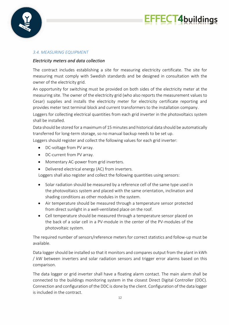
shows the respective module's location in the system. Marking must be done with engraved
sign. Signs type Dymo or Brothers are not accepted. Signs should be UV resistant.
All electrical components like grid inverters, actuators, electrical switches etc. must be marked
with a sign. Central equipment and grid inverters should be marked with designation, wire area
and fuse. Wires and components are marked at both ends so they become identifiable.
Labelling in documentation shall be in accordance with technical documentation.
An overview chart of the photovoltaic system as well as instructions for disconnecting should
be mounted at electrical panels and grid inverters.
Warning, prohibition and information signs
A sign making it clear that there is a photovoltaic system in the building shall be placed in the
building's floor plan so that it is seen in case of fire.
At the electric panels connected to the photovoltaic system should signs about the
photovoltaic systems (for example warnings about reverse voltage) be placed
At all the grid inverters should a sign be placed with the text corresponding to: "When switching
off the grid inverter, first switch off the AC side and then the DC side".
5.2. COMMISSIONING AND TESTING
The contractor should together with the client, coordinate the commissioning. Both the client
and the contractor should be present at testing, inspection and commissioning.
The contract includes adjustment and testing of the photovoltaic system before final
inspection and verifying this with attestations and protocols. Attestations and protocols shall
be handed over together with the technical documentation of the photovoltaic system. The
contract also includes testing of all parts of the photovoltaic system (included in the contract)
regarding operating instructions, indications, alarms etc.
Coordinated functional control
The contractor shall participate in the coordinated functional control covering the entire
system, including:
• Alarm transmission
• Collected measured values and presentation of these.
• Photovoltaic system
The different subsystems collaboration and function should be tested to determine if the
different contracting parts work together as intended.
Attestations and protocols verifying testing of the system must be signed with a personal
signature and name clarification as well as the date for each test.

18
Protocol for approved coordinated functional control should be handed over at the final
inspection for approved contract.
Completed coordinated functional control must be done, no later than two weeks before the
final inspection.
Testing of the photovoltaic system
The contractor shall perform a capacity measurement of the photovoltaic system. Every PV
array should be measured, and result be presented in a protocol. The measurement and
protocol should also include current solar radiation and temperature. All values must be
documented in the adjustment protocol.
Test of disconnection function for all protective relays, switches and automatic fuses should
be performed.
Measurement of power quality (PQ) shall be made to show that the system as a whole complies
with SS-EN 50160.
In addition to what is stated in Swedish standard SS 436 40 00 ELSÄK-FS 2008: 1 (amended
2010: 1) and IEC 60891, 60904-1-10, the contract also includes following tests and
measurements:
Capacity measurement on completed photovoltaic system to ensure that the systems capacity
is within +/- 5% of the power specified in the tender.
Capacity measurement shall be performed when the solar radiation exceeding 700 W / m².
In the capacity measurement, a calibrated reference cell should be used to determine the solar
radiation. The protocol from performed measurements should be handed over at latest a week
after the measurements were performed.
Testing of telecommunication
The following shall be tested:
• Connection and communication to weblog
• Login to website for visualization on computer screen
• Connection and communication to display screen
Protocols of performed tests must be available at the final inspection.
5.3. DOCUMENTATION
Final documentation must be delivered in scope according to regulations in the administrative
regulations.

19
The contractor delivers as-built documents, technical documentation and operating and
maintenance instructions of delivered components. The contract must include a detailed
description of the system's structure, function and operation, as well as data sheets of
components.
A comprehensive description of the system’s structure (components from drawings: PV-
modules, grid inverters, switches) and how to manage different operational cases as well as
assembly drawings for electrical panels and control panels must also be provided.
The contract includes delivery of a “Declaration of Conformity” which contains assurance that
the electrical installation meets the requirements for CE marking
Clear instructions for the photovoltaic system must be provided of how to prevent risks
regarding electrical distribution in case of emergency. The disconnection function of the
system must be described and a drawing showing the location of the safety switch must be
delivered. These instructions shall be placed at the fire brigade panel.
A supplementary technical specification to the as-built documents in Swedish shall be
submitted as well as preliminary dimensional drawings, layout drawing and the like on the
following materials:
• PV-modules including fastenings.
• Grid inverters
• Junction boxes.
All PV-modules should be delivered with a measuring protocol showing each module’s
electrical data. All PV-modules must be marked with an identification.
An overview chart with instructions of disconnecting the PV-system shall be located at each
connection to the buildings electricity system and at each grid inverter.
A valid test certificate from TÜV or similar organization must be attached showing that the
offered inverter has been tested and approved in accordance with SS-EN 61000-3-2 (or SS-EN
61000-3-12), SS-EN 61000-3-3 (alt. SS-EN 61000-3-11), SS-EN 61000-6-2 and SS-EN 61000-6-3.
The certificate should also be possible to identify digitally, for example at http://certipedia.com
or http://www.vde.com/certificate.
Construction documents
The contractor shall provide the following construction documents:
• Description of principle arrangement.
• Wind and roof load calculation
• Architectural diagrams of electrical installation
• Assembly drawing of PV-modules
20
• Energy calculation.
• Specific yield (kWh/m2, year).
• Number of PV modules and grid inverters.
• Dimensions of PV-modules
• Number of PV-modules per array and DC voltage for each PV-array.
• Installed nominal power (kWp) for both PV modules and grid inverters.
• Annual electricity production (kWh/year)
• Performance ratio.
Construction documents should be handed over to the client for review and approval, before
the start of the contract.
As-built documentations
The contractor shall provide the following as-built documentations:
1. Circuit diagram
2. Installation drawings and instructions for electricity panels and control panels.
3. External connection schemes or connection tables.
4. Single-line diagram
5. Cabling table.
6. Cabling list for sizing of wires and fuses.
As-built documents are provided with the inscription AS-BUILT DOCUMENTS and date.
As-built documents must be submitted to the client's CAD coordinator in non-editable media.
A specific drawing of the location of the PV-modules must also be delivered as dwg files
according to the client's CAD manual.
As-build documents are placed in binders for operation and maintenance.
Adjacent to the grid inverters, main wiring diagrams and schematics shall be placed in
transparent plastic frame.
Operation- and maintenance instructions
The contractor shall provide operating instructions for the photovoltaic system. The content
and scope of the operation and maintenance plan must be approved by the client.
Instructions are last delivered in conjunction with the final inspection. The instructions are
delivered both in two binders and in digitally form.
Instructions of how to operate the grid inverters shall be wrapped in plastic and placed
adjacent to the grid inverters.
Operation- and maintenance instructions should include:

21
1. Warranty conditions, boundary drawing and contact person during the warranty period
with address and list of telephone numbers for participating suppliers, contractors etc.
2. Description of the photovoltaic system (description of the system’s structure, functions
and maintenance instructions).
3. Troubleshooting Guide
4. Bill of materials, specifications in Swedish with list of spare parts.
5. Brochures
6. Description of technical protective measures
7. Description of protective measures and how to proceed in case of fire.
8. Fire safety documentation
9. Testing and adjustment protocol.
10. List of signs
11. As-built documents
The digital documentation's folder system must correspond to the binder’s tab system.
Everything that is registered in a binder must also be digitally documented. Brochures,
drawings and office documents should be converted to pdf files. Editable original files should
also be saved in the folders.
5.4. TRAINING AND EDUCATION
See the administrative regulations regarding times for education. Information and training
should be both practical and theoretical. A review of the photovoltaic system must be kept on
site after completion of the contract. The information must be such that the client can
independently manage the photovoltaic system.
The information shall at least include:
• The function and design of the photovoltaic system
• Simple troubleshooting
• Care and maintenance of the components and time intervals for this
• Safety precautions
• Instructions regarding work on roofs nearby the photovoltaic system.
• Instructions for monitoring via measurement data
6. AFTER FINAL INSPECTION
6.1. SUPERVISION, CARE AND MAINTENANCE OF ELECTRICAL AND TELECOMMUNICATION
INSTALLATIONS
The contractor must make the necessary service visits during the warranty period, however at
least 6, the month after the start of operation, after the end of each years 1-4 and 2 months
before the end of the warranty period. At the final inspection, a visitation plan is made in
consultation with the client.

22
The client must be informed in advance of the service visits and offered to be present. A written
record of each service visit is provided to the client after the visit.
At each service visit, a complete functional test of the photovoltaic system must be performed.
In addition to what is described in the section Testing, also produced electricity (kWh and kWh
/ kWp) for the photovoltaic system and the respective grid inverters must be tested and
compared with calculated production. In the event of deviations that may indicate a warranty
defect (product and power warranty), the client must be informed immediately.
In the event that the client receives state support for this photovoltaic installation, the
contractor must provide documentation to the client for reporting the production to the
responsible authority during the first 3 years.
All required service and maintenance during the warranty period must be included for all parts
/ units / device included in the contract.
Support in case of failure
In case of failure reported by the client or the operation manager, the contractor shall have a
reporting time of at most 72 hours.

23
![CITIZEN GROUP CSR Procurement Guideline...3 Citizen Watch CSR Procurement Guideline I Human Rights and Labor [I-1] Prohibit forced labor Suppliers are requested to employ all employees](https://img.pdfslide.us/doc/110x75/5f7ce882563b3b7c23152673/citizen-group-csr-procurement-guideline-3-citizen-watch-csr-procurement-guideline.jpg)