Embed Size (px)
Citation preview

30 PROTA Symposium: New Generation of Seismic Codes and New Technologies in Earthquake Engineering
Guideline Documents
Farzad Naeim Farzad Naeim, Inc.
Jack Moehle UC Berkeley

Why PBD for Tall Buildings?
30 PROTA Symposium: New Generation of Seismic Codes and New Technologies in Earthquake Engineering
February 2015 2
• The traditional code-based design everywhere is built on prescriptive rules and linear analysis.
• Using such an approach: – We can design building that are generally life-safe during
earthquakes – They generally have more capacity than indicated by our design
analysis
• But how much more capacity they have got? • What level of excitation is necessary to bring them
down? • The prescriptive code approach is incapable of
answering these questions.

Why PBD for Tall Buildings?
30 PROTA Symposium: New Generation of Seismic Codes and New Technologies in Earthquake Engineering
February 2015 3
• Tall Buildings are a special class of structures with very particular characteristics and requirements: – long period – multi-mode behavior – Significance of P-delta effects – large occupancy – impact of failure and/or collapse
• We have evolved: from linear static to dynamic to nonlinear; from deterministic to probabilistic.
• Computing advances have made nonlinear analysis practical.

• In fairness to the code-writers, codes are not generally written with tall buildings in mind.
• Let us look at building construction statistics in the United States:
1 to 3 Stories
4 to 13 Stories
93% 14 Stories and Taller
• You can not realistically expect code-writers to dedicate a large portion of their effort to address 1% of the buildings.
Why PBD for Tall Buildings?
6%
% of Buildings
1%
30 PROTA Symposium: New Generation of Seismic Codes and New Technologies in Earthquake Engineering
February 2015 4

• 2002 Los Angeles Building Code Story Drift Requirement:
Story Drift Ratio < 0.020/T1/3
• This provision, which was later retracted, probably did
not have a serious effect on design of low-rise buildings but was a huge straightjacket for design of tall buildings with long vibration periods
30 PROTA Symposium: New Generation of Seismic Codes and New Technologies in Earthquake Engineering
February 2015 5
Example:

Example: 0.0500 0.0450 0.0400 0.0350 0.0300 0.0250 0.0200 0.0150 0.0100 0.0050 0.0000
0.0 1.0 2.0 3.0 4.0 5.0
T (sec) 6.0 7.0 8.0 9.0 10.0
Dri
ft (
rad
)
Illustrations courtesy of CTBUH
30 PROTA Symposium: New Generation of Seismic Codes and New Technologies in Earthquake Engineering
February 2015 6

• Core Wall System – The great majority of
tall buildings under design or construction in western U.S. use this system.
30 PROTA Symposium: New Generation of Seismic Codes and New Technologies in Earthquake Engineering
February 2015 7
– But codes do not allow shear wall alone systems to exceed 240 feet of overall height.
– How did they get around that limitation? • How about hybrid systems or new systems
not envisioned by the code?
Examples of the Need
Figure courtesy of MKA

• Alternative Methods Clause in the Codes – Section 104.11 of 2012 IBC:
• “The provisions of this code are not intended to prevent the installation of any material or to prohibit any design or method of construction not specifically prescribed by this code, provided that any such alternative has been approved. An alternative material, design or method of construction shall be approved where the building official finds that the proposed design is satisfactory and complies with the intent of the provisions of this code, and that the material, method or work offered is, for the purpose intended, at least the equivalent of that prescribed in this code in quality, strength, effectiveness, fire resistance, durability and safety.”
30 PROTA Symposium: New Generation of Seismic Codes and New Technologies in Earthquake Engineering
February 2015 8
The Mechanism

• Alternative Methods Clause in the Codes – Section 12.6 of ASCE 7-10:
• "The structural analysis required by Chapter 12 shall consist of one of the types permitted in Table 12.6.1, based on the structure's seismic design category, structural system, dynamic properties, and regularity, or with the approval of the authority having jurisdiction, an alternative generally accepted procedure is permitted to be used.....”
• Section 1.3 of ASCE 7-10 also permits performance-based approaches that use analysis, testing, or a combination thereof, as acceptable alternative means.
30 PROTA Symposium: New Generation of Seismic Codes and New Technologies in Earthquake Engineering
February 2015 9
The Mechanism

• How do you establish equivalent or superior performance?
• You need: – An acceptable methodology – Acceptable seismic hazard evaluation
methods – Acceptable modeling and analysis
techniques – Rational acceptance criteria
There is a problem though!
30 PROTA Symposium: New Generation of Seismic Codes and New Technologies in Earthquake Engineering
February 2015 10

That is where guidelines come in!
30 PROTA Symposium: New Generation of Seismic Codes and New Technologies in Earthquake Engineering
February 2015 11

• The two mostly used guidelines are: – 2010 PEER-TBI – 2014 LATBSDC
• They both refer to: – ASCE 41and ASCE 7 Standards – ATC-72-1
• Jurisdictional differences in adaptation: – Los Angeles – San Diego – San Francisco – Seattle
30 PROTA Symposium: New Generation of Seismic Codes and New Technologies in Earthquake Engineering
February 2015 12
Guidelines

1. Introduction 2. Design Performance Objectives 3. Design Process Overview 4. Design Criteria Documentation 5. Seismic Input 6. Preliminary Design 7. Service Level Evaluation 8. MCE Evaluation 9. Presentation of Results 10. Project Review
2010 PEER-TBI Organization 104 pages
30 PROTA Symposium: New Generation of Seismic Codes and New Technologies in Earthquake Engineering
February 2015 13

1. Introduction 2. Intent, Scope, Justification, and Methodology 3. Analysis and Design Procedure
1. General 2. Modeling Requirements 3. Serviceability Requirements 4. Collapse Prevention Evaluation 5. Specific Provisions for R/C Structures
4. Peer Review Requirements 5. Seismic Instrumentation
2014 LATBSDC Organization 51 pages
30 PROTA Symposium: New Generation of Seismic Codes and New Technologies in Earthquake Engineering
February 2015 14

ASCE 41and the Guidelines
30 PROTA Symposium: New Generation of Seismic Codes and New Technologies in Earthquake Engineering
February 2015
• ASCE41 is officially intended for seismic rehabilitation of existing structures
• However, its component-based performance limits for NDP are routinely referenced by guidelines for performance based design of tall buildings
• Engineers who believe ASCE 41limits are too conservative, or are not applicable to their project, have the opportunity to present and substantiate other appropriate limits
• Peer review approval is always necessary for any deviation from ASCE 41

Performance Objectives
30 PROTA Symposium: New Generation of Seismic Codes and New Technologies in Earthquake Engineering
February 2015 16
• 2010 TBI: – Basic Performance Objective (BPO)
• Performance equivalent to Code design buildings • Two Level Design
– Enhanced Performance Objective (EPO) • Better than BPO • Specifics and criteria not laid out
• 2014 LATBSDC: – Serviceable performance under frequent events – Repairable following very rare events
• Hazard Levels Considered: – Serviceability: 43 years mean return period (50% in 30 years) – Very Rare Event:
– PEER-TBI: ASCE 7-05, 7-10 MCE – 2014 LATBSDC: MCER per ASCE 7-10 with clarifications

Analytical Procedures
30 PROTA Symposium: New Generation of Seismic Codes and New Technologies in Earthquake Engineering
February 2015
• ASCE-41 permits four types of analyses: 1. Linear elastic static procedure (LSP) 2. Linear dynamic procedure (LDP) or response
spectrum analysis 3. Non-linear static procedure (NSP) commonly
referred to as the push-over analysis, and 4. Dynamic nonlinear response analysis (NDP).
• Tall Building Design Guidelines permit only two:
1. 3D LDP or NDP for serviceability check 2. 3D NDP for all checks

30 PROTA Symposium: New Generation of Seismic Codes and New Technologies in Earthquake Engineering
More About Performance Objectives
1. Serviceable behavior: • building structural and nonstructural components retain their
general functionality during and after earthquake • Repairs, if necessary, are expected to be minor and could be
performed without substantially affecting the normal use and functionality of the building
2. A low probability of collapse under MCE or MCER type events. • Demands are checked for all structural members (lateral as
well as gravity system) • Claddings and their connections to the structure must
accommodate MCE or MCER displacements without failure

• Both guidelines use capacity design principles: – The capacity design criteria shall be described in
the project-specific seismic design criteria. – The structural system for the building shall be
clearly demonstrated to have well defined inelastic behavior where nonlinear action is limited to the clearly identified members and regions.
– All other members should be stronger than the elements designed to experience nonlinear behavior.
30 PROTA Symposium: New Generation of Seismic Codes and New Technologies in Earthquake Engineering
February 2015 19
Capacity Design

ple of Capacity Design Approa
C
A Symposium: New Generation of Seismic Codes and New Technologies in Earthquake Engi
Exam ch
Source: 2014 LATBSD
the building that are designed to dissipate energy and exhibit significant ductility is the essence
30 PROT neering
February 2015 20
of Capacity Design.
Typical zones and actions commonly designated for nonlinear behavior are identified in the following table. This table is not meant to be conclusive. Other zones may be included into the design based on sufficient justification.
Table C.3.3.2 Zones and actions commonly designated for nonlinear behavior
Structural System Zones and Actions
· Flexural yielding of Beam ends (except for transfer girders)
· Shear in Beam-Column Panel Zones · P-M-M* yielding at the base of columns (top of
foundation or basement podiums) · Braces (yielding in tension and buckling in
compression) · P-M-M yielding at the base of columns (top of
foundation or basement podiums) · Shear Link portion of the beams (shear yielding
preferred but combined shear and flexural yielding permitted).
· P-M-M yielding at the base of columns (top of foundation or basement podiums)
· Unbonded brace cores (yielding in tension and compression)
· P-M-M yielding at the base of columns (top of foundation or basement podiums)
· Shear yielding of web plates · Flexural yielding of Beam ends · P-M-M yielding at the base of the walls (top of
foundation or basement podiums) and other clearly defined locations throughout the height of the wall.
· Flexural yielding and/or shear yielding of link beams · Controlled rocking · Controlled settlement
Special Moment Resisting Frames (steel , concrete, or composite)
Special Concentric Braced Frames
Eccentric Braced Frames
Unbonded Braced Frames
Special Steel-Plate Shear Walls
R/C Shear Walls
Foundations
* yielding caused by combined axial force and uniaxial or biaxial flexure

• All actions must be classified as either – Force-Controlled, or – Deformation-Controlled
• Force-Controlled actions must further be categorized as either – Critical, or – Non-Critical
Classification of Structural Actions
30 PROTA Symposium: New Generation of Seismic Codes and New Technologies in Earthquake Engineering
February 2015 21

ExampleAcotions fin allClaterallloaad ressistingselemiefntsimcust bae cattegoiriozed ans either oforce-fcontrAolled ocr tions 3.5.4.1 Acceptance Criteria at the Component Level
deformation-controlled and if classified as force-controlled, as either critical, or noncritical
actions. Table 5 shows a representative and acceptable classification of such actions.
Table 5. Typical Classification of Component Actions
Component Seismic Action Classification Criticality
Below grade perimeter walls
Parking ramp walls N/A
Critical
Podium walls N/A
Critical
Tower core walls (over their entire height)
N/A
Critical
Core wall coupling beams N/A
Floor slabs N/A
Diaphragms with major shear transfer
Non-Critical
Critical
Gravity columns Critical
Foundations Non-Critical
Flexure Force Controlled Shear Force Controlled Flexure Deformation Controlled Shear Force Controlled Flexure Deformation Controlled Shear Force Controlled Flexure Deformation Controlled Shear Force Controlled Shear / Flexure Deformation Controlled Out of plane flexure Deformation Controlled around supports
Flexure Force Controlled Shear Force Controlled Axial Force Controlled Flexure Force Controlled Shear Force Controlled
Non-Critical
Critical
Critical Source: 2014 LATBSDC
30 PROTA Symposi2u0m14:LNATeBwSDGCeAnlteerrnaattiivoenAnoaflySsiesiasnmd iDcesCigondPeroscaednudreNew Technologies in Earthquake3E6ngineering
February 2015 22

Evaluation Procedures
30 PROTA Symposium: New Generation of Seismic Codes and New Technologies in Earthquake Engineering
February 2015
• Both guidelines require a three- dimensional detailed mathematical model of the physical structure
• Realistic estimates of stiffness, strength and damping
• Strength: – 2014 LATBSDC uses expected material
properties and reduction factor of 1.0. – 2010 PEER-TBI uses the same for MCE
but specified properties and code reduction factors for serviceability evaluation.

30 PROTA SymposiuTma: Nbelwe 3G.enReeraintiofnorocf eSdeisCmoicnCcordeetseanSdtiNffenweTseschPnroolopgieerstiineEsarthquake Engineering
ELxo spAen gce tl ees dT a lMl Bau i tl ed i nrgias Slt rSu ctt ru rea lnDge stihg n C o u n c i l
Table 2. Expected Material Strengths
Material Expected Strength
Yield Strength for Structural steel
Strength (ksi)
Hot-rolled structural shapes and bars ASTM A36/A36M ASTM A572/A572M Grade 42 (290) ASTM A992/A992M All other grades
Hollow Structural Sections ASTM A500, A501, A618 and A847
Steel Pipe ASTM A53/A53M
Plates All other products
1.5Fy
1.3Fy 1.1Fy 1.1Fy
1.3Fy
1.4Fy
1.1Fy
1.1Fy
Yield Strength for Reinforcing steel
1.17 times specified fy
Ultimate Strength for Concrete
1.3 times specified f ’c
Element Serviceability and Wind MCE-Level Nonlinear Models FeSbtrruucaturyra2l 0W1a5lls Flexural – 1.0 Ec *, ** Flexural – 0.75 Ig
Shear – 1.0 Ag Shear – 0.5 Ag 24

StCiofnfcnreteess Properties – 2010 PEER-1T.3 fBc' I
Ec shall be computed per ACI 318, using expected material strength per Table 7.1.
Gc shall be computed as Ec (2 (1+n )), where n shall be taken as 0.2.
Page 47
All other Products 1.1 fy Reinforcing Steel 1.17 fy
* fy is used to designate specified yield strength of steel materials in this Guideline. It is equivalent to Fy used in AISC standards. Table 7.2 Effective component stiffness values.
Component Flexural Rigidity
Shear Rigidity
Axial Rigidity
Structural steel Beams, Columns and Braces Composite Concrete Metal Deck Floors R/C Beams – nonprestressed R/C Beams – prestressed R/C Columns R/C Walls R/C Slabs and Flat Plates Notes:
EsI 0.5EcIg 0.5EcIg EcIg 0.5EcIg 0.75EcIg 0.5EcIg
GsA GcAg GcAg GcAg GcAg GcAg GcAg
EsA EcAg EcAg EcAg EcAg EcAg EcAg
30 PROTA Symposium: New Generation of Seismic Codes and New Technologies in Earthquake Engineering
February 2015 25

StCiofnfcrnete ess Properties – 2014 LATBSDC Ultimate Strength for 1.3 times specified f ’c
Table 3. Reinforced Concrete Stiffness Properties Element Serviceability and Wind MCE-Level Nonlinear Models
Flexural – 1.0 Ec *, ** Structural Walls Flexural – 0.75 Ig Shear – 1.0 Ag Shear – 0.5 Ag
Basement Walls Flexural – 1.0 Ig Shear – 1.0 Ag
Flexural – 0.8 Ig Shear – 0.5 Ag
Coupling Beams Flexural – 0.3 Ig Shear – 1.0 Ag
Flexural – 0.2 Ig Shear – 1.0 Ag
Diaphragms (in-plane only) Flexural – 0.5 Ig Shear – 0.8 Ag
Flexural – 0.25 Ig Shear – 0.25 Ag
Moment Frame Beams Flexural – 0.7 Ig Shear – 1.0 Ag
Flexural – 0.35 Ig Shear – 1.0 Ag
Moment Frame Columns Flexural – 0.9 Ig Shear – 1.0 Ag
Flexural – 0.7 Ig Shear – 1.0 Ag
* Modulus of elasticity is based on the following equations:
Ec = 57000 fc for f ’c ≤ 6000 psi
E = 40000 f ¢+1´106 c c
30 PROTA Symposium: New Generation of Seismic Codes and New Technologies in Earthquake Engineering
Fe2b0r1u4aLryA2T0B1S5DC Alternative Analysis and Design Procedure 1246
for f ’ > 6000 psi c (per ACI 363R-921) ** Nonlinear fiber elements automatically account for cracking of concrete because the concrete fibers have zero tension stiffness.

30 PROTA Symposium: New Generation of Seismic Codes and New Technologies in Earthquake Engineering
1. Use 2.5% damping instead of 5% damping but permit DCR = 1.5 for deformation controlled members for serviceability.
2. 2014 LATBSDC limits DCR to 0.70 for force controlled members in serviceability check.
3. 2010 PEER requirements for collapse prevention are more elaborate and detailed than 2011 LATBSDC
4. No minimum base shear capacity requirement in either document
PEER-TBI & LATBSDC Provisions

Analysis Methods
30 PROTA Symposium: New Generation of Seismic Codes and New Technologies in Earthquake Engineering
February 2015
• Serviceability: – Can use either
1. Linear Response Spectrum Analyses – CQC mode combination – 90% mass participation
2. Nonlinear Dynamic Response Analyses
• For MCE evaluation: – Must use
• Nonlinear Dynamic Response Analyses • Inherent torsional properties of the structural
system should always be considered.

Accidental Eccentricity (AE)
30 PROTA Symposium: New Generation of Seismic Codes and New Technologies in Earthquake Engineering
February 2015
• 2014 LATBSDC – Consider implications during serviceability
evaluation – Address if significant during MCE evaluation
• 2010 PEER TBI – Do not need to consider
• Consideration of AE in nonlinear analyses
may require multiple evaluations.

• Floor diaphragms shall be included in the mathematical model using realistic stiffness properties.
• Regardless of the relative rigidity or flexibility of floor diaphragms, flexibility of diaphragms with significant force transfer (for example podium levels and other setback levels) shall be explicitly included in the mathematical model.
• Diaphragm chord and drag forces shall be established in a manner consistent with the floor characteristics, geometry, and well- established principles of structural mechanics.
• Both shear and bending stresses in diaphragms must be considered.
• At diaphragm discontinuities, such as openings and re-entrant corners, the dissipation or transfer of edge (chord) forces combined with other forces in the diaphragm shall be evaluated.
30 PROTA Symposium: New Generation of Seismic Codes and New Technologies in Earthquake Engineering
February 2015 30
Floor Diaphragms

3.4.3.1. Elastic Response Spectrum Analyses 30 PROTA Symposium: New Generation of Seismic Codes and New Technologies in Earthquake Engineering At least 90 percent of the participating mass of the structure shall be included in the calculation
Loincaludded in tChe Coollampse Pbreveinntionaevtaluiaotionn(sese Section 3.5). The structure shall be evaluated
for the following load combinations:
accidental torsion are considered in order to establish whether accidental torsion needs to be
(a) R e s pons e S pe ct r um A nal ys i s
1.0D + Lexp + 1.0Ex + 0.3Ey
1.0D + Lexp + 1.0Ey + 0.3Ex
(b) Nonl i near Dynam i c Re s pons e A nal ys i s
1.0D + Lexp + 1.0E
where D is the service dead load and Lexp is the expected service live load. Lexp may be taken
as 25% of the unreduced live load unless otherwise substantiated and shall be included in all
gravity calculations and P-D analyses. C.3.4.3. Building Code response modification factors do not apply (that is, R, W0, r , and Cd,
are all taken as unity). Lexp need not be included in the mass calculations.
of response for each principal horizontal direction. Modal responses shall be combined using the February 2015 31

30 PROTA Symposium: New Generation of Seismic Codes and New Technologies in Earthquake Engineering
P-Δ Inclusion • P-Δ effects must be
included in all analyses
P-Delta effect included P-Delta effect excluded
ROOF DRIFT ANGLE vs. NORMALIZED BASE SHEAR Pushover (NEHRP '94 k=2 pattern); LA 20-Story
0.1 0.08 0.06 0.04 0.02
0
0.12
0.14
0 0.01 0.02 0.03
Roof Drift Angle
0.04 0.05
Norm
ali
zed
Ba
se S
hea
r (V
/W)
P-Delta effect included P-Delta effect excluded
Figure courtesy of Prof. Helmut Krawinkler

Modeling Nonlinear Behavior
Figure courtesy of Prof. Greg Deierlein
30 PROTA Symposium: New Generation of Seismic Codes and New Technologies in Earthquake Engineering
February 2015

Modeling Nonlinear Behavior
30 PROTA Symposium: New Generation of Seismic Codes and New Technologies in Earthquake Engineering
February 2015
• Concentrated plasticity model for beams and columns and fiber elements for walls are most common
• All other elements and components that in combination significantly contribute to or affect the total or local stiffness of the building should be included in the mathematical model.
• Axial deformation of gravity columns in a core-wall system is one example of effects that should be considered in the structural model of the building
Figure courtesy of MKA

Modeling Strength / Stiffness Degradation
30 PROTA Symposium: New Generation of Seismic Codes and New Technologies in Earthquake Engineering
February 2015
• 2010 PEER TBI – Provides detailed guidelines on four
approved methods for modeling degradation
• 2014 LATBSDC – Adopts the first two of the detailed
procedures contained in 2010 PEER.

2010 PEER-TBI Degradation Modeling Options
Figure courtesy of Prof. Helmut Krawinkler
30 PROTA Symposium: New Generation of Seismic Codes and New Technologies in Earthquake Engineering
February 2015

Soil-Foundation-Structure-Interaction (SFSI)
• Naeim & Stewart (2008) demonstrated the difficulties of realistic modeling of SFSI in a design environment.
• 2010 PEER-TBI has two recommended modeling techniques
• 2014 LATBSDC recommends a single approach for this.
30 PROTA Symposium: New Generation of Seismic Codes and New Technologies in Earthquake Engineering
February 2015
2010 PEER TBI Suggested Modeling Techniques for SFSI
2014 LATBSDC
30 PROTA Symposium: New Generation of Seismic Codes and New Technologies in Earthquake Engineering
February 2015
SFSI

• Modeling, Rocking and Uplift: – Foundation components that have significant
flexibility or will experience significant inelastic behavior shall be modeled following the same approach outlined for components of the superstructure.
30 PROTA Symposium: New Generation of Seismic Codes and New Technologies in Earthquake Engineering
February 2015 39
Foundations

• Seismic isolation and energy dissipation devices shall be modeled based on data from laboratory tests representing conditions anticipated during MCE / MCER shaking.
• If the properties of these devices vary significantly, lower and upper bound properties shall be modeled.
• The consequences of attaining device limits must be demonstrated to be tolerable to the structure.
30 PROTA Symposium: New Generation of Seismic Codes and New Technologies in Earthquake Engineering
February 2015 40
Response Modification Devices

lower bound estimate of forces in the foundation below the tower. 3 design forces for the podium floor diaphragms and perimeter walls
connections. The LB analysis provides a lower-bound estimate of f load path and an upper-bound estimate of forces in the foundation case will govern the design forces for the tower foundation elemen
010 PEER-TBI – Refers to ATC-72 provisions – Lower and upper bound stiffness
values for diaphragms and walls are used to envelope the backstay effect impact.
014 LATBSDC – Uses a similar but simplified
procedure where only lower and upper bound stiffness of the diaphragms are modeled.
0 PROTA Symposium: New Generation of Seismic Codes and New Technologies in Earthquake Engineering
BackstaEcyIeff Effects • 2
• 2
Diaphragms at the podium and below 0.5 0.5
0.20 to 0.25 0.20 to 0.25 Gc A
C.3.2.3. Any lower part of a tall building structure that is larger in floor plate, and contains substantially increased seismic-force resistance in comparison to the tower above, can be considered a podium. Backstay effects
L o s arAenthg ee lterasnsTfaerl lofBluatielrdailnfog rsceSst frruocmt uthr ael
seismic-force resisting elements in the tower into adddiiatpihornagamlsealtetmhe epnodtisumthaantd ebexlioswt. within the podium, typically through one or more floor diap2h.raAgmmosd.elTwhheichlautseesralolwfeor-rbcoeunrde(sLiBst)astnifcfneesisnassumptions for floor diaphragms
the podaituthme ploedviuemlsa,nad nbedlofwo.rce transfer through floor diaphragms at these levels, helps a tall building resist seismic overturning forces. (Illustration from ATC-72) analyses. The sensitivity analyses, where applicable, shall be performed in addition to the
analysTehs piserfcoormmedpousninegnsttifofnfeossvperorptuerrtineisnpgrovriedsedisitnaTnacbele i3s. referred to as the backstay effect, based on its simTilaablerit4y. Sttoifftnheess bpaarcakmseptearns foorfUapcpearnBtioluenvdearnbdeLaomwe.rIBtoiusnadlMsoodseolsmetimes called “shear reversal” beca us e t he s hear i n the s ei sm ic- f orc e r esis t ing elem ent s ca n change direction within the podDiuiamphrlaegvmes last.thSeipnocdieumthaendsbtieflofwness properties of the elements, particularly diaphragms, are
, and the associated orces in the backstay below the tower. This ts.
both iEncfIleuff ential on the seismic design0.a5nd uncerta0.i2n0,toa0s.2e5nsitivity analysis is required. The UB anGac lAysis provides an upper-bound0.5estimate o0f.2f0otroc0e.s25in the backstay load path and a
This case will govern the
D e s i g n C o u n c i l
Table 4 contains recommendations for UB and LB Stiffness parameters for backstay sensitivity
Stiffness Parameters UB LB
C.3.2.3. Any lower part of a tall building structure that is larger in floor plate, and contains substantially increased seismic-force
Februreasriysta2n0ce15in comparison to the tower above, can be considered a podium. Backstay effects are the transfer of lateral forces from the
41

Damping • A particularly thorny issue
– In nonlinear analyses most of the damping is represented by hysteretic behavior of the elements
– Some small additional viscous damping may be justified for: • Energy dissipation provided by components and systems
not explicitly modeled • As necessary to avoid numerical instability
• 2014 LATBSDC – Limits viscous damping to 2.5% for both
serviceability and MCE.
• 2010 PEER-TBI – 2.5% for linear serviceability evaluation – Refers to ATC-72 for nonlinear evaluation
30 PROTA Symposium: New Generation of Seismic Codes and New Technologies in Earthquake Engineering
February 2015
• Three General Methods: – Code Scaling in time-domain so that the
average of spectra of records stays above design spectrum over a range of periods
– Spectral Matching by modifying the frequency content of the ground motion
– Conditional Mean Spectrum (CMS) by scaling at a particular period or periods
• All three methods permitted by both guidelines
30 PROTA Symposium: New Generation of Seismic Codes and New Technologies in Earthquake Engineering
February 2015 43
Ground Motion Selection and Scaling

S our ce: FEMA 451B
30 PROTA Symposium: New Generation of Seismic Codes and New Technologies in Earthquake Engineering
February 2015 44
Code Scaling

Spectral Matching
S our ce: Ninyo and More
30 PROTA Symposium: New Generation of Seismic Codes and New Technologies in Earthquake Engineering
February 2015 45

CMS Scaling
30 PROTA Symposium: New Generation of Seismic Codes and New Technologies in Earthquake Engineering
February 2015 46
From Jack W. Baker, The Conditional Mean Spectrum: A Tool for Ground Motion Selection, ASCE Journal of Structural Engineering, February 2010.

Ground Motion Selection and Scaling
30 PROTA Symposium: New Generation of Seismic Codes and New Technologies in Earthquake Engineering
February 2015
• A minimum of 7 pairs is usually required • If CMS is used, 2014 LATBSDC requires at
least two suites of 7 pairs. • Attention should be paid to higher modes being
addressed by scaling (0.2T to 1.5T • Most practicing engineers prefer matching
– One must be careful as, matched motion contains less record to record dispersion
– This is one reason 2014 LATBSDC uses 1.5 x mean rather than Mean + x% of SD

2014 LATBSDC R/C Specific Requirements
• Beams in Special R/C Moment Frames – In regions where post-yield rotations are
expected, the member shall be detailed in the vertical direction as required by ACI 318-11 Eq. (21-5).
30 PROTA Symposium: New Generation of Seismic Codes and New Technologies in Earthquake Engineering
February 2015

2014 LAT3.6B.2.1. SIntermDediaCte and SRpecifi/edCStr engtShs pecific Requirements
• High-Sstretngrth evalune shgall ntothbe lesCs thano0.00n4 (scee Frigeure 3t.6e.2.1).
document is defined as concrete with f’c equal to or greater than 6,000 psi.
The following concrete compressive strength limits as indicated in Table 7 shall be attained. In
addition, the strain attained at the point of maximum strength shall not be less than 0.002 and the
strain attained past the point of maximum strength at stress level equal to half of the maximum
Table 7. Intermediate and final strength values for high-strength concrete
Specified Strength (psi) Intermediate and final strength values (psi)
6,000 <f ’c < 8000 · 6,000 at 28 days
· 1.0 f’c at 90 days
8,000 <f ’c < 12,000 · 6,000 at 28 days · 0.75 f’c at 90 days · 1.0 f’c at 365 days
f’c > 12,000 · 0.50 f’c at 28 days · 0.75 f’c at 90 days · 1.0 f’c at 365 days
Strain, e Figure 3.6.2.1. Strain capacity requirements
Stre
ss, s s max
0.5s max
e > 0.0020 e > 0.0040
30 PROTA S2y
0m14
pLoAsTiuBSm
D:CNAeltwern
Gati
evene
Arnaaltyisoisn
ano
df
DS
eesiisgmn P
icro
Cce
odudrees and New Technologies in Earthq
4u4ake Engineering
February 2015

Peer Review Requirements • Both documents have extensive peer
review requirements which will be discussed in a separate presentation.
30 PROTA Symposium: New Generation of Seismic Codes and New Technologies in Earthquake Engineering
February 2015

Instrumentation Requirements • 2010 PEER TBI
– No requirements • 2011 LATBSDC
– Detailed requirements – Consistent with CGS / CSMIP
30 PROTA Symposium: New Generation of Seismic Codes and New Technologies in Earthquake Engineering
February 2015

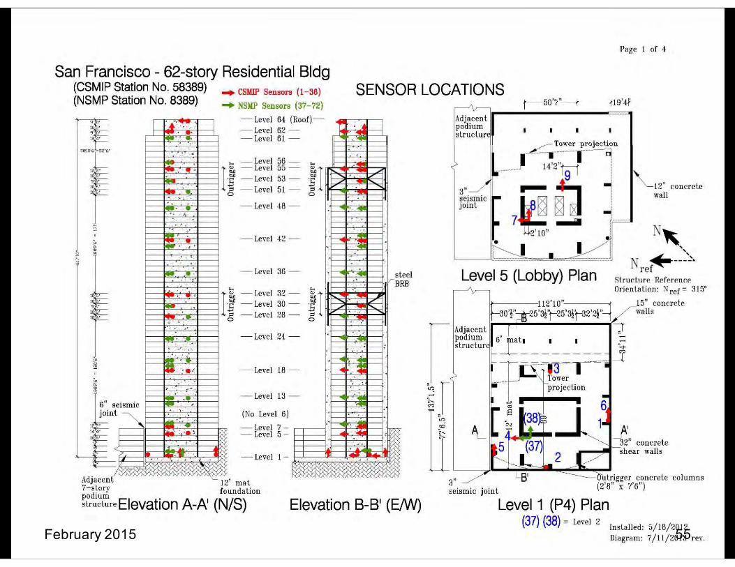
LATBSDC Instrumentation Requirements
30 PROTA Symposium: New Generation of Seismic Codes and New Technologies in Earthquake Engineering
February 2015 52
• Objective: – Improve safety and reliability of building systems by providing data to
improve computer modeling and enable damage detection for post- event condition assessment
• Plan and Review: – An instrumentation plan shall be prepared by the EOR and submitted to
SPRP and Building Official for review and approval. – SPRP Approved instrumentation plans shall be marked accordingly on
the structural drawings. – If the building is intended to be included in the inventory of buildings
monitored by the California Geologic Survey (CGS) then the recorders and accelerometers must be of a type approved by CGS.

Image courtesy of Mr. John Hooper, MKA

February 2015 55

February 2015 56

February 2015 57

February 2015 58

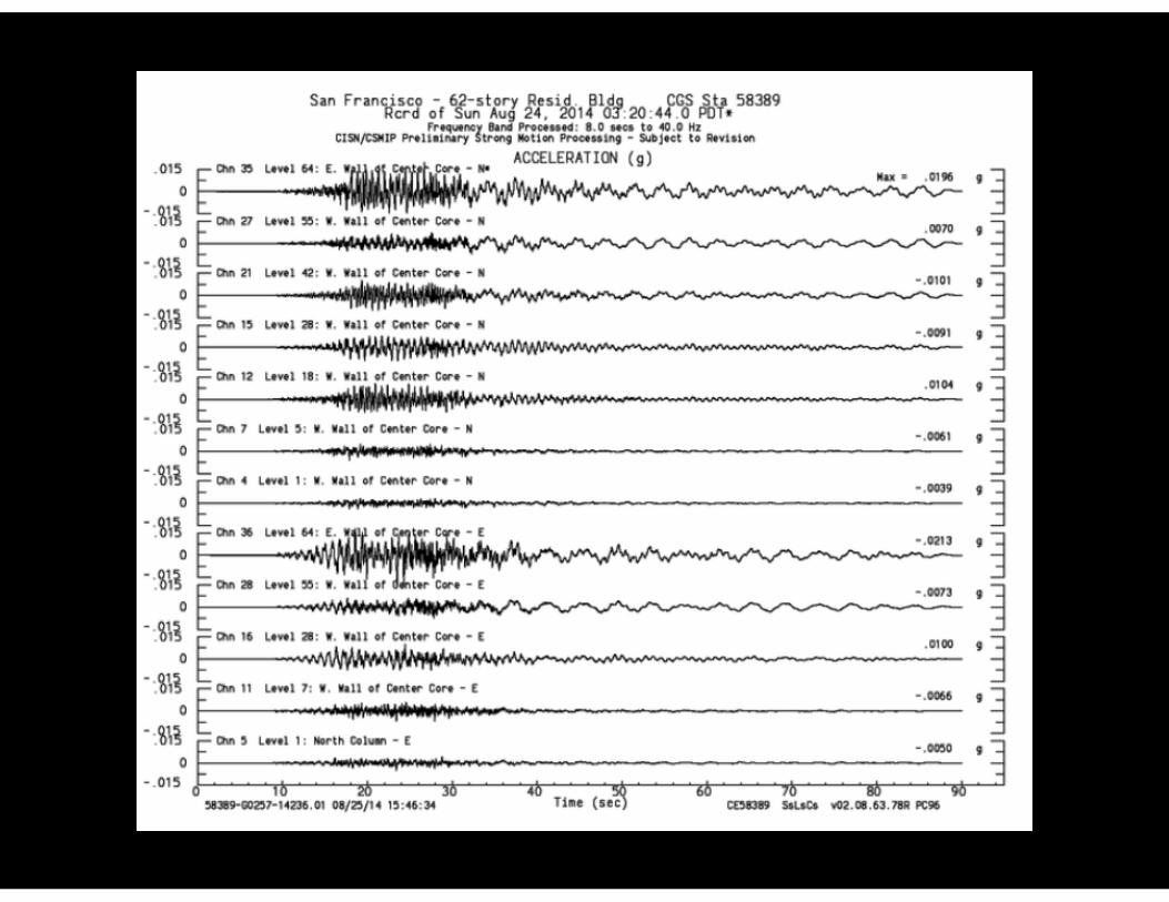

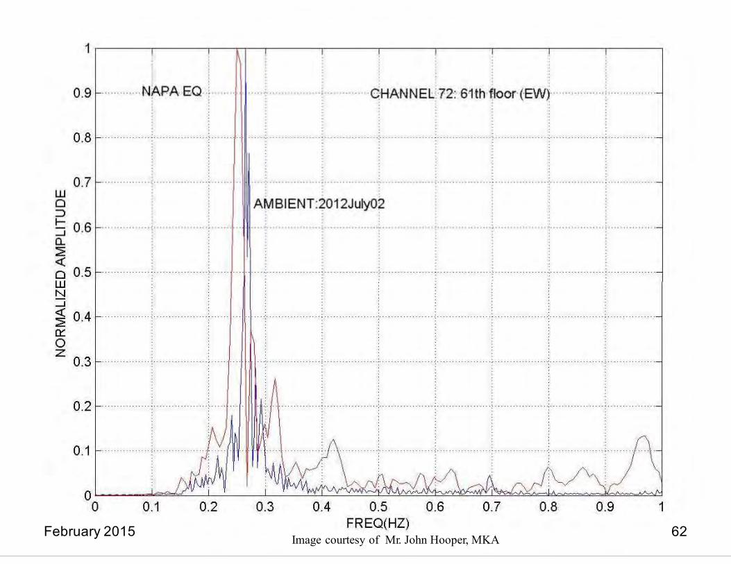
Image courtesy of Mr. John Hooper, MKA February 2015 62

February 2015 63

• Key differences to be aware of: – Reduction Factors:
• In 2014 LATBSDC, ϕ = 1.0, always. • In 2010 PEER-TBI, ϕ = 1.0 for serviceability; ϕ = code values for MCE
– Risk Categories: • 2014 LATBSDC considers various categories • 2010 PEER-TBI assumes Risk Category to be II
– Modeling Dispersion: • 2014 LATBSDC uses 1.5 x mean • 2010 PEER-TBI uses 1.5 x mean, or
mean + 1.3 x SD > 1.2 x mean, depending on the situation.
Acceptance Criteria
30 PROTA Symposium: New Generation of Seismic Codes and New Technologies in Earthquake Engineering
February 2015 64

• 2014 LATBSDC
Risk Category Reduction Factor
30 PROTA Symposium: New Generation of Seismic Codes and New Technologies in Earthquake Engineering
February 2015 65

Acceptance Criteria -- Maximum Drift
• Absolute Maximum Transient Drift Angle Limits – Serviceability:
0.005 overall
– MCE or MCER: 0.030 x Ki max average at any story
0.045 x Ki max. interstory drift at any story
under any record
30 PROTA Symposium: New Generation of Seismic Codes and New Technologies in Earthquake Engineering
February 2015

Acceptance Criteria -- Residual Drift
• Collapse Prevention:
0.010 x Ki average max. of time histories
0.015 x Ki maximum from any
30 PROTA Symposium: New Generation of Seismic Codes and New Technologies in Earthquake Engineering
February 2015

• Strength Loss: – In any nonlinear dynamic response analysis,
deformation imposed at any story shall not result in a loss of total story strength that exceeds 20% of the initial strength.
Acceptance Criteria
30 PROTA Symposium: New Generation of Seismic Codes and New Technologies in Earthquake Engineering
February 2015 68

Acceptance Criteria -- Serviceability
30 PROTA Symposium: New Generation of Seismic Codes and New Technologies in Earthquake Engineering
February 2015
• 2014 LATBSDC – Force-Controlled Actions:
Strength Demand < 0.7 x Capacity
– Deformation-Controlled Actions: • Response Spectrum Analysis
▪ Strength Demand < 1.50 x Capacity, (Risk Category I, II)
▪ Strength Demand < 1.20 x Capacity, (Risk Category III) ▪ Talk to SPRP for Risk Category > III
• Nonlinear Analysis ▪ Can use up to IO limit of ASCE 41

Acceptance Criteria -- MCE
30 PROTA Symposium: New Generation of Seismic Codes and New Technologies in Earthquake Engineering
February 2015
• 2010 PEER – Force-Controlled Actions:
• Two Groups: – Critical Actions
» failure mode pose severe consequences to structural stability under gravity and/or lateral loads
» Design for mean + 1.3 to 1.5 times SD » Use code reduction factors, ϕ = 0.75 for shear
– Noncritical Actions » Design for mean demand values and ϕ = 1.0.
• 2011 LATBSDC – Essentially the same, except uses 1.5 times mean,
ϕ = 1.0, and a factor for risk category.

30 PR OTA Symposium: New Generation of Seismic Codes and New Technologies in Earthquake Engineering
Acce3p.5.4t.1a.1 Fnorcce-CeontroClled Arcitiotnes ria -- MCE
• Force-Cmodoe pnostesrsoevelrleecodnseqAuenccesttioostrnuctsura:l stability under gravity and/or lateral
– CriticaloaldsA. Focrctei-oconntrosll:ed critical actions shall satisfy:
Fuc £ k ifFn ,e
where
(a) Cri ti cal A ct ions
in which the failure Force-controlled critical actions are those force-controlled actions 2014 LATBSDC
Fuc = 1.5 times the mean value of demand. Fn,e = nominal strength as computed from applicable material codes but based on
expected material properties.
f = 1.0.
k i = Risk reduction factor given in Table 6.
EXCEPTION: For buildings located in the Los Angeles region if the
serviceability acceptance criteria are satisfied per requirements of Section
3.4.5.1, then k i may be taken as 1.0.
C.3.5.4.1.1(a) Use of the mean value would imply a significant probability of failure with associated consequences. The use of mean plus one standard deviation is more appropriate.
February 20 However, when fewer than 20 ground motion pairs are used in nonlinear dynamic response analysis, little confidence can be placed in the computed value of the standard deviation or the mean. A factor of 1.5 is utilized to represent a simple yet reasonable means to reduce
Different in PEER-TBI
Different in PEER-TBI
Different in PEER-TBI
15

EXCEPTION: For buildings located in the Los Angeles region if the
serviceability acceptance criteria are satisfied per requirements of Section
3.4.5.1, then k i may be taken as 1.0.
30 PROTA Symposium: New Generation of Seismic Codes and New Technologies in Earthquake Engineering
C.3.5.4.1.1(b) Since such failures do not result in structural instability or potentially life-
Acceptance Criteria -- MCE
• Force-Cion stnructturraloinsltalbeilitdy or pAotenctiatllyiolifen-thrseate:ning damage such as diaphragm shear and axial forces in diaphragm chords and drag members as well as foundation forces.
– Non-CrFoirtciec-coantrlolleAd ncontcriioticanl asctio:ns shall satisfy:
Fu £ k ifFn,e
where
Fu = the mean demand obtained from the suite of analyses,
Noncritical actions are those force-controlled actions for which failure do2es0n1ot4reLsuAlt TBSDC
Different in PEER-TBI
L o s A n g e l e s T a l l B u i l d i n g s S t r u c t u r a l D e s i g n C o u n c i l
N on-Cr itic a l A c tions
Fn,e = nominal strength as computed from applicable material codes but based on
expected material properties.
f = 1.0.
k i = Risk reduction factor given in Table 6.
threatening damage, use of mean demand values are justified. Please note that degradation and loss of story strength are limited by other provisions contained in this document.
February 2015

Upper Limit on Column Axial Forces
30 PROTA Symposium: New Generation of Seismic Codes and New Technologies in Earthquake Engineering
February 2015
• Large axial forces reduce available R/C column ductility
• 2014 LATBSDC
– MCE: P < 0.4f’cAg
• 2010 PEER-TBI
– MCE: P < balanced load < 0.3f’cAg

Acceptance Criteria -- MCE • Deformation-Controlled Actions:
▪ < Ki x Primary CP limits in ASCE-41 ▪ Larger values may be used only if substantiated
by appropriate laboratory tests. ▪ If exceeded, strength degradation, stiffness
degradation and hysteretic pinching shall be considered and base shear capacity of the structure shall not fall below 90% of the base shear capacity at deformations corresponding to ASCE 41Primary CP limits
– 2010 PEER-TBI is not as rigid and refers to ASCE 41 as a source of information.
2014 LATBSDC
30 PROTA Symposium: New Generation of Seismic Codes and New Technologies in Earthquake Engineering
February 2015

APPLICATION EXAMPLES
30 PROTA Symposium: New Generation of Seismic Codes and New Technologies in Earthquake Engineering
February 2015 75
Applications
30 PROTA Symposium: New Generation of Seismic Codes and New Technologies in Earthquake Engineering
February 2015
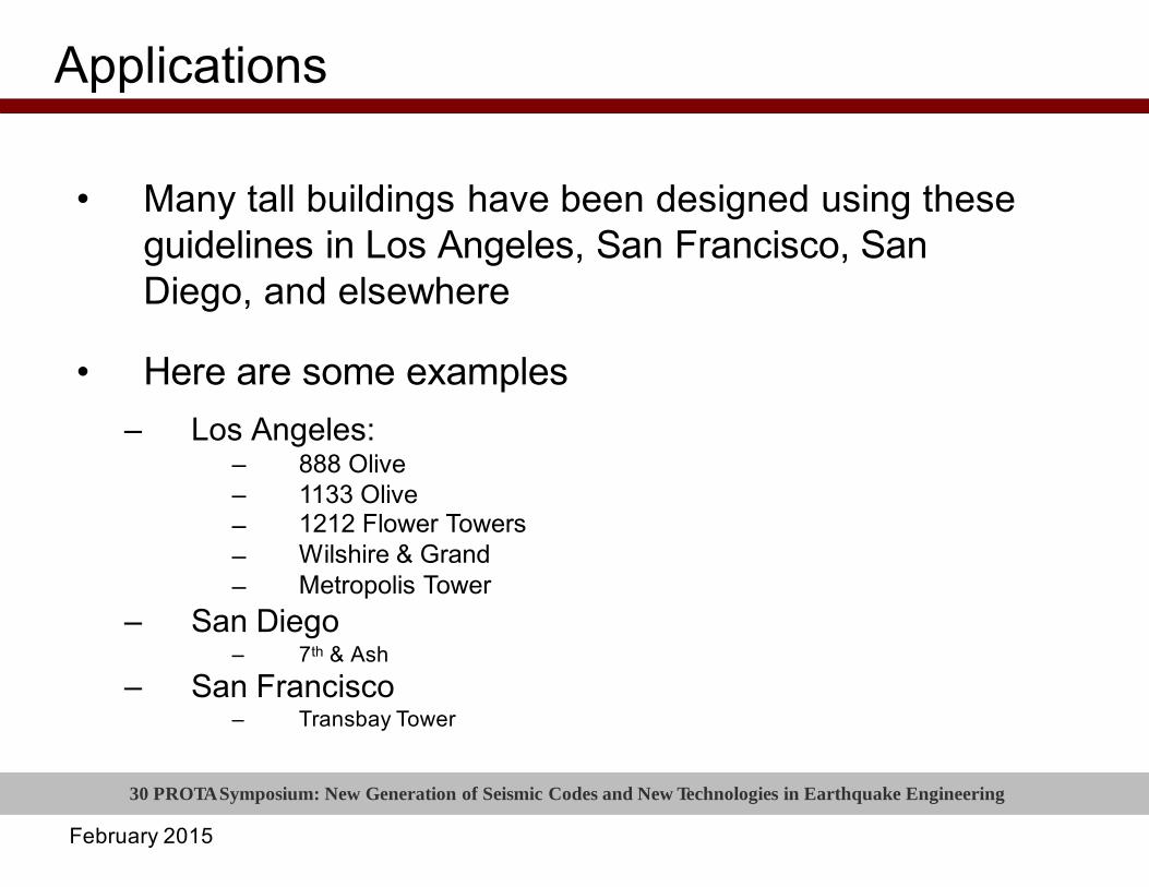
• Many tall buildings have been designed using these guidelines in Los Angeles, San Francisco, San Diego, and elsewhere
• Here are some examples – Los Angeles:
– – – – –
888 Olive 1133 Olive 1212 Flower Towers Wilshire & Grand Metropolis Tower
– San Diego – 7th & Ash
– San Francisco – Transbay Tower

Illustrations a3n0d dPrRawOinTgAs cSoyumrtepsoysoiuf mOn:nNi GewrouGpeannedrGatloiotmnaonf-SSiemispmsoinc Codes and New Technologies in Earthquake Engineering
• 888 Olive Street in downtown Los Angeles – 34 stories – Core wall construction – Podium – Subterranean levels – Basement walls – Flat plates – Gravity columns
February 2015 77
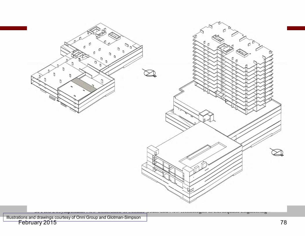
30 PROTA Symposium: New Generation of Seismic Codes and New Technologies in Earthquake Engineering Illustrations and drawings courtesy of Onni Group and Glotman-Simpson
February 2015 78

30 PROTA Symposium: New Generation of Seismic Codes and New Technologies in Earthquake Engineering
LEVEL 1 0.00'
LEVEL 2 20.00'
LEVEL 3 32.67'
LEVEL 4 45.33'
LEVEL 5 58.00'
LEVEL 6 70.67'
LEVEL 7 83.33'
LEVEL 8 96.00'
LEVEL 9 108.67'
LEVEL 10 121.33'
LEVEL 11 134.00'
LEVEL 12 146.67'
LEVEL 13 159.33'
LEVEL 14 172.00'
LEVEL 15 184.67'
LEVEL 16 197.33'
LEVEL 17 210.00'
LEVEL 18 222.67'
LEVEL 19 235.33'
LEVEL 20 248.00'
LEVEL 21 260.67'
LEVEL 22 273.33'
LEVEL 23 286.00'
LEVEL 24 298.67'
LEVEL 25 311.33'
LEVEL 26 324.00'
LEVEL 27 336.67'
LEVEL 28 349.33'
LEVEL 29 362.00'
LEVEL 30 374.67'
LEVEL 31 387.33'
LEVEL 32 400.00'
LEVEL 33 412.67'
LEVEL 34 425.33'
LEVEL 35 438.00'
LEVEL 36 450.67'
LEVEL 37 463.33'
LEVEL 38 476.00'
LEVEL 39 488.67'
LEVEL 40 501.33'
LEVEL 41 514.00'
LEVEL 42 526.67'
LEVEL 43 539.33'
LEVEL 44 552.00'
LEVEL 45 564.67'
LEVEL 46 577.33'
LEVEL 47 590.00'
LEVEL 48 602.67'
LEVEL 49 615.33'
LEVEL P1 -11.00' LEVEL P2 -22.00' LEVEL P3 -33.00'
P5 -45.00'
1 1 ' - 0 " 1 1 ' - 0 " 1 1 ' - 0 " 2 0 ' - 0 " 1 2 ' - 8 " 1 2 ' - 8 " 1 2 ' - 8 " 1 2 ' - 8 " 1 2 ' - 8 " 1 2 ' - 8 " 1 2 ' - 8 " 1 2 ' - 8 " 1 2 ' - 8 " 1 2 ' - 8 " 1 2 ' - 8 " 1 2 ' - 8 " 1 2 ' - 8 " 1 2 ' - 8 " 1 2 ' - 8 " 1 2 ' - 8 " 1 2 ' - 8 " 1 2 ' - 8 " 1 2 ' - 8 " 1 2 ' - 8 " 1 2 ' - 8 " 1 2 ' - 8 " 1 2 ' - 8 " 1 2 ' - 8 " 1 2 ' - 8 " 1 2 ' - 8 " 1 2 ' - 8 " 1 2 ' - 8 " 1 2 ' - 8 " 1 2 ' - 8 " 1 2 ' - 8 " 1 2 ' - 8 " 1 2 ' - 8 " 1 2 ' - 8 " 1 2 ' - 8 " 1 2 ' - 8 " 1 2 ' - 8 " 1 2 ' - 8 " 1 2 ' - 8 " 1 2 ' - 8 " 1 2 ' - 8 " 1 2 ' - 8 " 1 2 ' - 8 " 1 2 ' - 8 " 1 2 ' - 8 " 1 2 ' - 8 " 1 2 ' - 8 "
3 3 ' - 0 " 5 9 0 ' - 0 "
P R O P E R T Y L I N E
P R O P E R T Y L I N E
4 9 4 ' - 0 " 9 6 ' - 0 "
CO
LOR
LE
GE
ND
FL
OO
R
AR
EA
B
UIL
DIN
G
CO
MM
ON
AR
EA
S
TO
R
E
AR
EA
R
ES
IDE
NT
IAL
AM
EN
ITY
SE
RV
I
CE
AR
EA
S
TO
RA
G
E
P1
PA
RK
AD
E
P2
PA
RK
AD
E
P3
PA
RK
AD
E
L1 P
AR
KA
DE
L1 R
ES
ID
EN
TIA
L LO
BB
Y
CO
MM
ER
CIA
L/ R
ET
AIL
STO
RA
GE
STO
RA
GE
S
TOR
AG
E
BIK
E
STO
RA
GE
BIK
E
STO
RA
GE
ELE
VA
TO
R
RE
SI
DE
NT
IAL
AM
EN
ITY
RE
SI
DE
NT
IAL
AM
EN
ITY
TOW
N
HO
US
ES
S T A I R S
RE
SI
DE
NT
IAL
RE
SI
DE
NT
IAL
L2 P
AR
KA
DE
L3 P
AR
KA
DE
L4 P
AR
KA
DE
L5 P
AR
KA
DE
CH
RIS
D
IKE
AK
OS
A
RC
HIT
EC
TS
SECT
ION
S
CA
LE:
1/32" = 1'-0"
OL
IVE
ST.
MIX
ED
-US
E
DE
VE
LO
PM
EN
T 817 - 825 H
ill St. &
820 S.
Design
Develop
ment
August 26th,
A30
A201 1/32" = 1'-0"
February 2015
1 Sec
tion 9

30 PROTA Symposium: New Generation of Seismic Codes and New Technologies in Earthquake Engineering
LEVEL 1 0.00'
LEVEL 2 17.33'
LEVEL 3 30.00'
LEVEL 4 42.67'
LEVEL 5 55.33'
LEVEL 6 68.00'
LEVEL 7 80.67'
LEVEL 8 93.33'
LEVEL 9 106.00'
LEVEL 10 118.67'
LEVEL 11 131.33'
LEVEL 12 144.00'
LEVEL 13 156.67'
LEVEL 14 169.33'
LEVEL 15 182.00'
LEVEL 16 194.67'
LEVEL 17 207.33'
LEVEL 18 220.00'
LEVEL 19 232.67'
LEVEL 20 245.33'
LEVEL 21 258.00'
LEVEL 22 270.67'
LEVEL 23 283.33'
LEVEL 24 296.00'
LEVEL 25 308.67'
LEVEL 26 321.33'
LEVEL 27 334.00'
LEVEL 28 346.67'
LEVEL 29 359.33'
LEVEL 30 372.00'
LEVEL 31 384.67'
LEVEL 32 397.33'
LEVEL 33 410.00'
LEVEL 34 422.67'
LEVEL 35 435.33'
LEVEL 36 448.00'
LEVEL 37 460.67'
LEVEL 38 473.33'
LEVEL 39 486.00'
LEVEL 40 498.67'
LEVEL 41 511.33'
LEVEL P1 -12.00' LEVEL P2 -23.92' LEVEL P3 -35.84'
1 1 ' - 1 1 " 1 1 ' - 1 1 " 1 2 ' - 0 " 1 7 ' - 4 " 1 2 ' - 8 " 1 2 ' - 8 " 1 2 ' - 8 " 1 2 ' - 8 " 1 2 ' - 8 " 1 2 ' - 8 " 1 2 ' - 8 " 1 2 ' - 8 " 1 2 ' - 8 " 1 2 ' - 8 " 1 2 ' - 8 " 1 2 ' - 8 " 1 2 ' - 8 " 1 2 ' - 8 " 1 2 ' - 8 " 1 2 ' - 8 " 1 2 ' - 8 " 1 2 ' - 8 " 1 2 ' - 8 " 1 2 ' - 8 " 1 2 ' - 8 " 1 2 ' - 8 " 1 2 ' - 8 " 1 2 ' - 8 " 1 2 ' - 8 " 1 2 ' - 8 " 1 2 ' - 8 " 1 2 ' - 8 " 1 2 ' - 8 " 1 2 ' - 8 " 1 2 ' - 8 " 1 2 ' - 8 " 1 2 ' - 8 " 1 2 ' - 8 " 1 2 ' - 8 " 1 2 ' - 8 " 1 2 ' - 8 " 1 2 ' - 8 " 1 2 ' - 8 "
W.
12TH
STR
EE
T
AL
LEY
PA
RK
ING
PA
RK
ING
PA
RK
ING
PA
RK
ING
PA
RK
ING
PA
RK
ING
PA
RK
ING
PA
RK
ING
GA
RB
AG
E
PA
RK
ING
PA
RK
ING
PA
RK
ING
PA
RK
ING
PA
RK
ING
PA
RK
ING
RE
S.
LOB
BY
EL
EV
. EL
EV
. EL
EV
. EL
EV
. EL
EV
. EL
EV
. EL
EV
. EL
EV
. EL
EV
.
PO
DIU
M
AM
EN
ITY
ELE
V.
EL
EV
. EL
EV
. EL
EV
. EL
EV
. EL
EV
. EL
EV
. EL
EV
. EL
EV
. EL
EV
. EL
EV
. EL
EV
. EL
EV
. EL
EV
. EL
EV
. EL
EV
. EL
EV
. EL
EV
. EL
EV
. EL
EV
. EL
EV
. EL
EV
. EL
EV
. ME
CH
. ME
CH
.
PA
RK
ING
PA
RK
ING
RES.
HE
LIP
AD
EXIS
TIN
G
OFFIC
E
BU
ILDI
NG
TOWE
R 1
BE
YO
ND
P R O P E R T Y L I N E
P R O P E R T Y L I N E
CO
UR
TYAR
D
LEVEL 1 0.00'
LEVEL 2 17.33'
LEVEL 3 30.00'
LEVEL 4 42.67'
LEVEL 5 55.33'
LEVEL 6 68.00'
LEVEL 7 80.67'
LEVEL 8 93.33'
LEVEL 9 106.00'
LEVEL 10 118.67'
LEVEL 11 131.33'
LEVEL 12 144.00'
LEVEL 13 156.67'
LEVEL 14 169.33'
LEVEL 15 182.00'
LEVEL 16 194.67'
LEVEL 17 207.33'
LEVEL 18 220.00'
LEVEL 19 232.67'
LEVEL 20 245.33'
LEVEL 21 258.00'
LEVEL 22 270.67'
LEVEL 23 283.33'
LEVEL 24 296.00'
LEVEL 25 308.67'
LEVEL 26 321.33'
LEVEL 27 334.00'
LEVEL 28 346.67'
LEVEL 29 359.33'
LEVEL 30 372.00'
LEVEL 31 384.67'
LEVEL 32 397.33'
LEVEL 33 410.00'
LEVEL 34 422.67'
LEVEL 35 435.33'
LEVEL 36 448.00'
LEVEL 37 460.67'
LEVEL 38 473.33'
LEVEL 39 486.00'
LEVEL 40 498.67'
LEVEL 41 511.33'
LEVEL P1 -12.00' LEVEL P2 -23.92' LEVEL P3 -35.84'
PA
RK
ING
PA
RK
ING
PA
RK
ING
PA
RK
ING
PA
RK
ING
PA
RK
ING
W. 12TH
STR
EE
T
RE
S.
LOB
BY
EL
EV
. EL
EV
. EL
EV
. EL
EV
. EL
EV
. EL
EV
. EL
EV
. EL
EV
. EL
EV
. EL
EV
. EL
EV
. EL
EV
. EL
EV
. EL
EV
. EL
EV
. EL
EV
. EL
EV
. EL
EV
. EL
EV
. EL
EV
. EL
EV
. EL
EV
. EL
EV
. EL
EV
. EL
EV
. EL
EV
. EL
EV
. EL
EV
. EL
EV
. EL
EV
. EL
EV
. EL
EV
. EL
EV
. EL
EV
. EL
EV
. EL
EV
. EL
EV
. EL
EV
. EL
EV
. EL
EV
. EL
EV
. ME
CH
. ME
CH
.
RE
S.
AM
EN
ITY
HE
LIP
AD
RE
S.
LOB
BY
PA
RK
ING
PA
RK
ING
PA
RK
ING
PA
RK
ING
PA
RK
ING
PA
RK
ING
PA
RK
ING
PA
RK
ING
P R O P E R T Y L I N E
EX
ISTIN
G
ALLE
Y
P R O P E R T Y L I N E
CH
RIS
D
IKE
AK
OS
A
RC
HIT
EC
TS
BUILD
ING
SEC
TION
S
FL
OW
ER
ST.
MIX
ED
-US
E
DE
VE
LO
PM
EN
T 1212 S
. Flower S
treet, Los A
ngeles, CA
DESIG
N
DEVELO
PM
ENT
August 26, 2013
A30
1 TOW
ER 2
BU
ILDIN
G
SE
CTIO
N
A201 1/32" = 1'-0"
A201
1/32" = 1'-0"
February 2015
2 TOW
ER 1
BU
ILDIN
G
SE
CTIO
N

February 2015

30 PROTA Symposium: New Generation of Seismic Codes and New Technologies in Earthquake Engineering
Thank you!
February 2015