Embed Size (px)
Citation preview
National Renewable Energy Laboratory NWTC – Certification Team
Rev Date Author Signature Date Approval Signature Notes
GUIDELINE DG04
Wind Turbine Design
Gearbox Design Analysis
DG04 000203 Page 2 of 151If printed, document may not be up to date. Printed on 2/24/00
Rev. Description
000111 Draft
NOTICEThis report was prepared as an account of work sponsored by an agency of the United States government. Neither the United Statesgovernment nor any agency thereof, nor any of their employees, makes any warranty, express or implied, or assumes any legal liability orresponsibility for the accuracy, completeness, or usefulness of any information, apparatus, product, or process disclosed, or representsthat its use would not infringe privately owned rights. Reference herein to any specific commercial product, process, or service by tradename, trademark, manufacturer, or otherwise does not necessarily constitute or imply its endorsement, recommendation, or favoring bythe United States government or any agency thereof. The views and opinions of authors expressed herein do not necessarily state orreflect those of the United States government or any agency thereof.
The present document might be copied and distributed only as far as necessary for the scope of a United States certification process.
DG04 000203 Page 3 of 15147If printed, document may not be up to date. Printed on 2/24/00
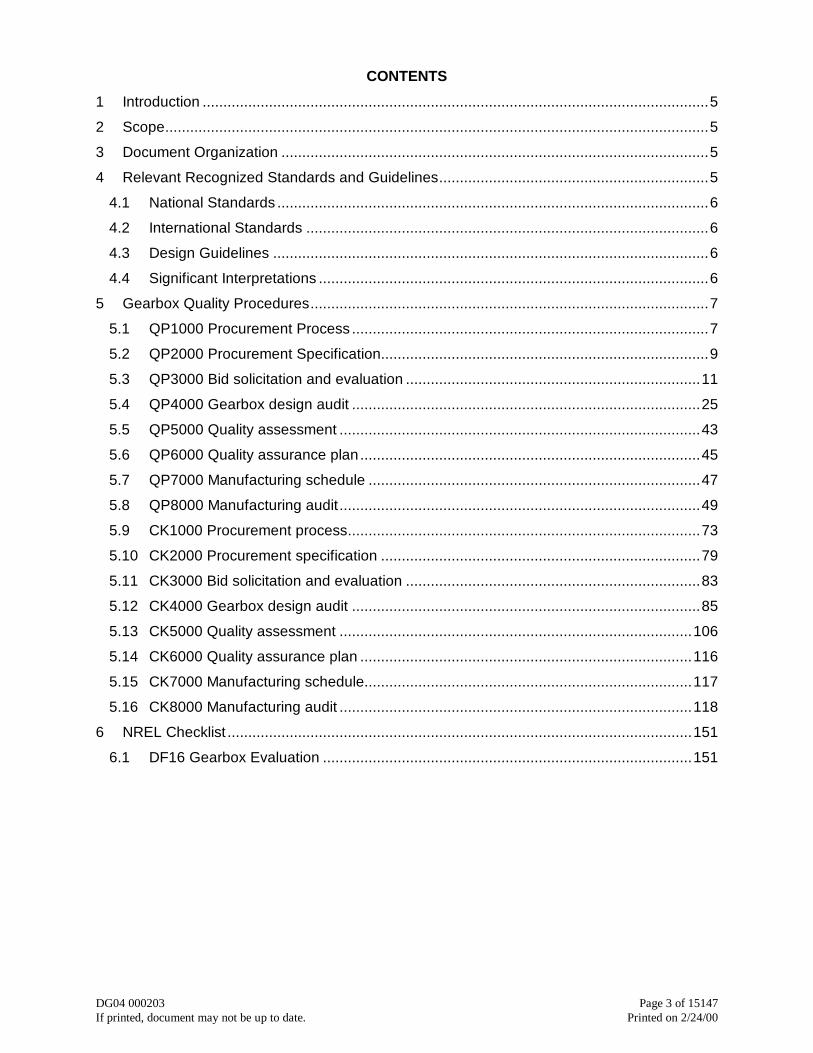
CONTENTS
1 Introduction ..........................................................................................................................5
2 Scope...................................................................................................................................5
3 Document Organization .......................................................................................................5
4 Relevant Recognized Standards and Guidelines.................................................................5
4.1 National Standards ........................................................................................................6
4.2 International Standards .................................................................................................6
4.3 Design Guidelines .........................................................................................................6
4.4 Significant Interpretations ..............................................................................................6
5 Gearbox Quality Procedures................................................................................................7
5.1 QP1000 Procurement Process ......................................................................................7
5.2 QP2000 Procurement Specification...............................................................................9
5.3 QP3000 Bid solicitation and evaluation .......................................................................11
5.4 QP4000 Gearbox design audit ....................................................................................25
5.5 QP5000 Quality assessment .......................................................................................43
5.6 QP6000 Quality assurance plan..................................................................................45
5.7 QP7000 Manufacturing schedule ................................................................................47
5.8 QP8000 Manufacturing audit.......................................................................................49
5.9 CK1000 Procurement process.....................................................................................73
5.10 CK2000 Procurement specification .............................................................................79
5.11 CK3000 Bid solicitation and evaluation .......................................................................83
5.12 CK4000 Gearbox design audit ....................................................................................85
5.13 CK5000 Quality assessment .....................................................................................106
5.14 CK6000 Quality assurance plan ................................................................................116
5.15 CK7000 Manufacturing schedule...............................................................................117
5.16 CK8000 Manufacturing audit .....................................................................................118
6 NREL Checklist ................................................................................................................151
6.1 DF16 Gearbox Evaluation .........................................................................................151

DG04 000203 Page 4 of 15147If printed, document may not be up to date. Printed on 2/24/00
National Renewable Energy LaboratoryAppendix E
DG04 000203 Page 5 of 15147If printed, document may not be up to date. Printed on 2/24/00
1 IntroductionThis document is one of a set of Design Guidelines (DG) developed by the National Renew-able Energy Laboratory (NREL) to assist manufacturers and designers with the task of devel-oping and presenting a comprehensive wind turbine design. The guidelines provide useful tipsfor developing, analyzing and presenting a wind turbine design suitable to submit for Certifica-tion. They are NOT a set of requirements or in anyway intended to replace the standards cho-sen by the manufacturer or certification body. They are intended to be a set of suggestions tohelp the designer in completing their work.
Quality procedures are very important in gearbox design/specification and production. In thisDG a suggested quality system is presented. It is by no means the only quality system that amanufacturer can establish. But parts of it or all of it could be used if the manufacturer de-cides that it is useful and efficient for their situation. Regardless of what system is used thestandards call for a quality system.
The original draft of this guideline was performed by Geartech Inc. under contract to NREL.They were drafted as a comprehensive set of quality procedures and checklists to guide de-signers, procurement officials, design auditors, manufacturing engineers or anyone who playsa role in the development of gearboxes for wind turbines. Each of the NREL sponsored guide-lines are then reviewed by industry experts to assure that they represent reasonable practice.They are revised periodically to assure they represent current practice.
The advice provided in this and other DG is not intended to represent a comprehensive planfor wind turbine design, but instead to complement and suggest alternatives to current designpractices. Following any or all of the suggestions set forth in this or any DG will not inherentlyimprove a design or guarantee its Certification, nor does it relieve its designers, engineers ormanufacturers of any liability.
2 ScopeThis Design Guideline presents suggestions for procurement, specification, design, quality as-sessment for gearboxes intended for use in wind turbines. It is one of a suite of Design Guide-lines intended to assist with the application of the International Standards listed in section 4.
3 Document OrganizationThis document is organized differently than other NREL DGs in that it presents a suggestedquality system for wind turbine gearboxes rather than textbook style technical design guide-lines. There are sufficient gearing standards and text books available for such purposes. ThisDG presents quality procedures for each stage of the gearbox development process andchecklists to help remind and record the successful completion of each of the stages. Theseprocedures and checklists can form a common set of terminology for all the different peopleand organizations that must collaborate to complete a successful gearbox development.
4 Relevant Recognized Standards and GuidelinesThe following is a list of standards, guidelines and other documents both referenced in thistext, and considered useful corollary material for the reader. At the time of publication, theeditions indicated were valid. All listed documents are subject to revision, and the reader isencouraged both to apply the most recent edition and record the edition of any documents ap-plied in the design process. In this guideline there are additional standards referenced. They
National Renewable Energy LaboratoryAppendix E
DG04 000203 Page 6 of 15147If printed, document may not be up to date. Printed on 2/24/00
are not listed here since their significance is better understood within the context of the discus-sion being presented in that text.
4.1 National Standards
AGMA/AWEA 921-A97 Recommended Practices for Design and Specification of Gearboxesfor Wind Turbine Generator Systems.
4.2 International Standards
IEC 61400-22: (Draft) Wind turbine generator systems. Wind turbine certification
IEC 61400-2: (1996-04), Wind turbine generator systems. Safety of small wind turbines
IEC 61400-1 Ed.2: (1999-02), Wind turbine generator systems. Safety Requirements
4.3 Design Guidelines
DG01: Loads Analysis
DG02: Strength Analysis
DG03: Yaw and Pitch Rolling Bearing Life
4.4 Significant Interpretations
Currently none are available.
National Renewable Energy LaboratoryAppendix E
DG04 000203 Page 7 of 15147If printed, document may not be up to date. Printed on 2/24/00
5 Gearbox Quality Procedures5.1 QP1000 Procurement Process
No. QP1000Company Name QUALITYPROCEDURE Rev. A
SHEET 1 OF 2
BY: Author DATE (date written)Procurement Process
CKD: Checker DATE (date checked)
1. Scope
1.1 This procedure covers the steps involved in procuring gearboxes.
2. Referenced Documents
2.1 AGMA/AWEA 921-A97 Recommended Practices for Design and Specification of Gearboxes forWind Turbine Generator Systems.
2.2 (Company Name) Specifications:
CK1000 QP1000 Procurement process
CK2000 QP2000 Procurement specification
CK3000 QP3000 Bid solicitation and evaluation
CK4000 QP4000 Gearbox design audit
CK5000 QP5000 Quality assessment
CK6000 QP6000 Quality assurance plan
CK7000 QP7000 Manufacturing schedule
CK8000 QP8000 Manufacturing audit
3. Terminology
3.1 Procurement process- The process of procuring gearboxes consisting of:
• Develop procurement specification
• Solicit bids
• Evaluate proposals/ select final bidders
• Meet for design reviews
• Select gear manufacturer
• Audit gearbox design
• Award Contract
National Renewable Energy LaboratoryAppendix E
DG04 000203 Page 8 of 15147If printed, document may not be up to date. Printed on 2/24/00
No. QP1000Company Name QUALITYPROCEDURE Rev. A
SHEET 2 OF 2
BY: Author DATE (date written)Procurement Process
CKD: Checker DATE (date checked)
Procurement Process (continued)
• Review and approve engineering drawings
• Review and approve quality assurance (QA) plan
• Review and approve manufacturing schedule
• Approve start of manufacturing
• Audit manufacturing
• Audit tests
• Audit gearbox startup
3.2 Bidder- Gear manufacturer who submits a proposal in response to bid solicitation.
3.3 Gear specialist- An engineer knowledgeable in design, manufacturing, and application of gear-boxes.
3.4 Gear manufacturer- A manufacturer specializing in the manufacture of gearboxes.
3.5 Purchaser- Company purchasing a gearbox from a gear manufacturer.
3.6 Proposal- Gearbox design, QA Plan, manufacturing schedule, pricing, and warranty offered by abidder.
3.7 Contract- Agreement between purchaser and gear manufacturer.
4. Significance and Use
4.1 Procurement process- AGMA/AWEA 921-A97, Annex D explains the procurement process in-cluding procurement specification, QA plan, quality control tests, quality documentation, and re-sponsibilities of purchasers and gear manufacturers (see CK1000).
5. Procedure
5.1 Checklists- CK2000 through CK9000 shall be used for guidelines for all aspects of the procure-ment process from writing the procurement specification to auditing gearbox startup.
5.2 Quality procedures- QP2000 through QP9000 shall be used for quality procedures for all as-pects of the procurement process from writing the procurement specification to auditing gearboxstartup.
5.3 Management- The procurement process involves many steps that evolve over time (typically atleast one year). Therefore, the purchaser must have resources adequate to ensure that eachstep of the procurement process is properly implemented and all requirements of the procure-ment specification are met. See CK1000 for overall guidelines covering the procurement proc-ess.
National Renewable Energy LaboratoryAppendix E
DG04 000203 Page 9 of 15147If printed, document may not be up to date. Printed on 2/24/00
5.2 QP2000 Procurement Specification
No. QP2000Company Name QUALITYPROCEDURE Rev. A
SHEET 1 OF 2
BY: Author DATE (date written)Procurement Specification
CKD: Checker DATE (date checked)
1. Scope
1.1 This procedure covers writing procurement specifications.
2.1.1.1.1.1.1 Referenced Documents
2.1 AGMA/AWEA 921-A97 Recommended Practices for Design and Specification of Gearboxes forWind Turbine Generator Systems.
2.2 (Company) Specifications:
1.1.1.1.2 CK1000 QP1000 Procurement process
1.1.1.1.3 CK2000 QP2000 Procurement specification
3. Terminology
3.1 Procurement specification- Specification designed and maintained by the purchaser that definesthe application, load spectrum, and minimum requirements for design, manufacturing, qualityassurance, testing, and gearbox performance (see CK2000).
4. Significance and Use
4.1 Procurement specification- AGMA/AWEA 921-A97, Clause 4 is a guide for developing a pro-curement specification for wind turbine gearboxes.
4.2 Features- The procurement specification defines requirements and methodology for obtainingreliable gearboxes for wind turbine service. A good procurement specification does the follow-ing:
• Defines purchaser’s requirements
• Provides common language to aid communication between purchaser, bidders, andgear manufacturer
• Provides methods for comparing competing proposals
• Specifies quality assurance inspections, tests, and acceptance criteria
5. Procedure
5.1 Responsibilities- The procurement Specification shall be designed and maintained by the pur-chaser. The gear manufacturer shall design and maintain a quality assurance (QA) plan that isadequate to achieve quality goals defined by the procurement specification.
National Renewable Energy LaboratoryAppendix E
DG04 000203 Page 10 of 15147If printed, document may not be up to date. Printed on 2/24/00
No. QP2000Company Name QUALITYPROCEDURE Rev. A
SHEET 2 OF 2
BY: Author DATE (date written)Procurement Specification
CKD: Checker DATE (date checked)
5.2 Management- The purchaser shall commit resources adequate to properly implement, distribute,and maintain the procurement specification.
5.3 Procurement specification- AGMA/AWEA 921-A97 shall be used as a guide for developing aprocurement specification.
5.4 Checklists- CK2000 shall be used for guidelines for content of a procurement specification.
5.5 Procurement process- CK1000 and QP1000 shall be used for guidelines covering the procure-ment process.
5.6 Technical requirements- The procurement specification shall be audited by a gear specialist toensure technical requirement are adequately specified.
National Renewable Energy LaboratoryAppendix E
DG04 000203 Page 11 of 15147If printed, document may not be up to date. Printed on 2/24/00
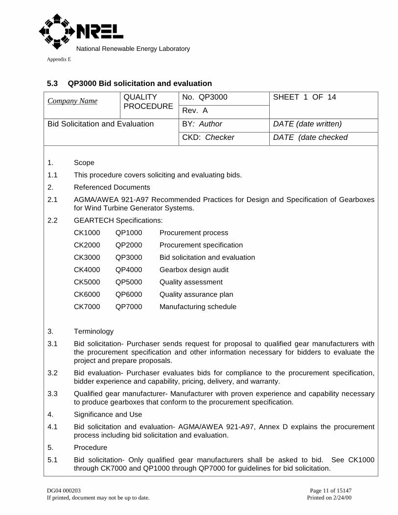
5.3 QP3000 Bid solicitation and evaluation
No. QP3000Company Name QUALITYPROCEDURE Rev. A
SHEET 1 OF 14
BY: Author DATE (date written)Bid Solicitation and Evaluation
CKD: Checker DATE (date checked
1. Scope
1.1 This procedure covers soliciting and evaluating bids.
2. Referenced Documents
2.1 AGMA/AWEA 921-A97 Recommended Practices for Design and Specification of Gearboxesfor Wind Turbine Generator Systems.
2.2 GEARTECH Specifications:
CK1000 QP1000 Procurement process
CK2000 QP2000 Procurement specification
CK3000 QP3000 Bid solicitation and evaluation
CK4000 QP4000 Gearbox design audit
CK5000 QP5000 Quality assessment
CK6000 QP6000 Quality assurance plan
CK7000 QP7000 Manufacturing schedule
3. Terminology
3.1 Bid solicitation- Purchaser sends request for proposal to qualified gear manufacturers withthe procurement specification and other information necessary for bidders to evaluate theproject and prepare proposals.
3.2 Bid evaluation- Purchaser evaluates bids for compliance to the procurement specification,bidder experience and capability, pricing, delivery, and warranty.
3.3 Qualified gear manufacturer- Manufacturer with proven experience and capability necessaryto produce gearboxes that conform to the procurement specification.
4. Significance and Use
4.1 Bid solicitation and evaluation- AGMA/AWEA 921-A97, Annex D explains the procurementprocess including bid solicitation and evaluation.
5. Procedure
5.1 Bid solicitation- Only qualified gear manufacturers shall be asked to bid. See CK1000through CK7000 and QP1000 through QP7000 for guidelines for bid solicitation.
National Renewable Energy LaboratoryAppendix E
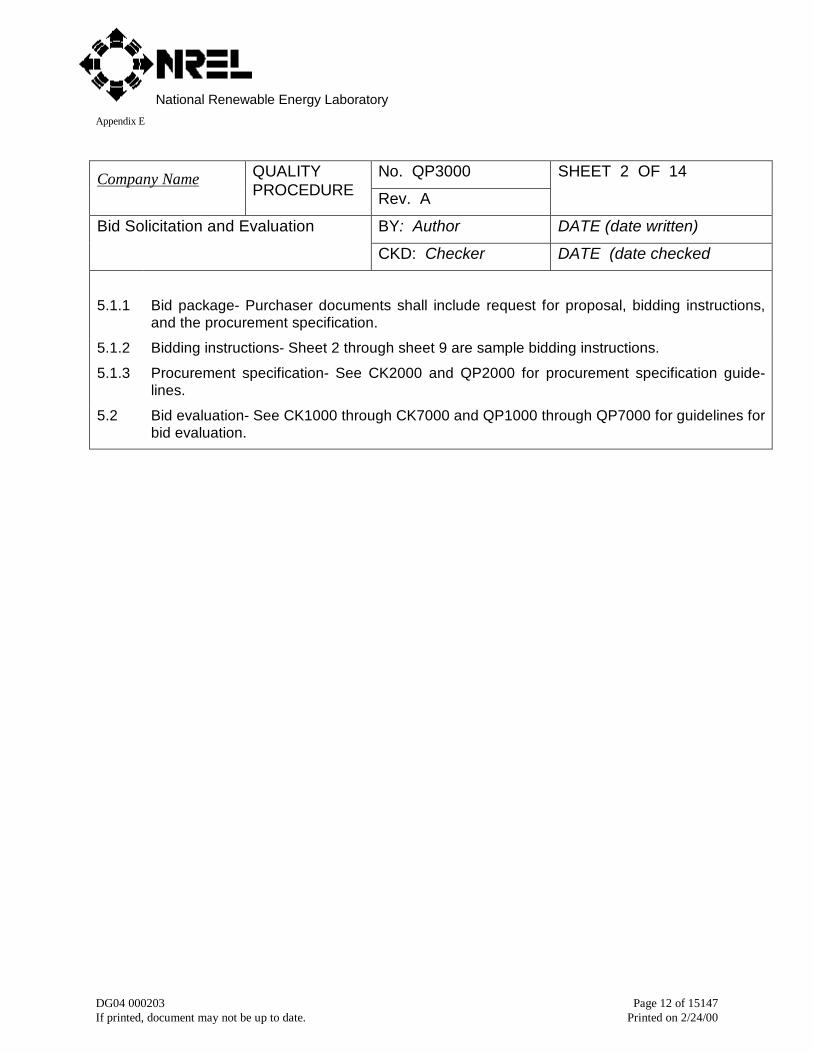
DG04 000203 Page 12 of 15147If printed, document may not be up to date. Printed on 2/24/00
No. QP3000Company Name QUALITYPROCEDURE Rev. A
SHEET 2 OF 14
BY: Author DATE (date written)Bid Solicitation and Evaluation
CKD: Checker DATE (date checked
5.1.1 Bid package- Purchaser documents shall include request for proposal, bidding instructions,and the procurement specification.
5.1.2 Bidding instructions- Sheet 2 through sheet 9 are sample bidding instructions.
5.1.3 Procurement specification- See CK2000 and QP2000 for procurement specification guide-lines.
5.2 Bid evaluation- See CK1000 through CK7000 and QP1000 through QP7000 for guidelines forbid evaluation.

National Renewable Energy LaboratoryAppendix E
DG04 000203 Page 13 of 15147If printed, document may not be up to date. Printed on 2/24/00
No. QP3000Company Name QUALITYPROCE-DURE
Rev. A
SHEET 3 OF 14
BY: Author DATE (date written)Bid Solicitation and Evaluation
CKD: Checker DATE (date checked
BIDDING INSTRUCTIONS
To be considered, proposals must show full understanding and compliance with Procurement SpecificationNo. <number>. Additionally, the following requirements must be met:
• Proposals shall be received at Purchaser no later than close of business on the day specified in theRequest For Proposal that invokes Procurement Specification No. <number>.
• Proposals shall be Lump Sum, First, and Firm.
• Proposals shall include the following:
• Completed proposal including pricing, delivery, and warranty
• List of exceptions to procurement specification
• Preliminary Quality Assurance Plan
• Completed questionnaire
• Layout (assembly) drawing of gearbox
• Outline dimension drawing of gearbox
• Metallurgical and geometric data for all gears
• Bearing data
• Load/life calculations for gears and bearings
• Lubrication data
• Proposals shall be sent to :
<addressee>
<address>
<address>
<address>
National Renewable Energy LaboratoryAppendix E
DG04 000203 Page 14 of 15147If printed, document may not be up to date. Printed on 2/24/00
No. QP3000Company Name QUALITYPROCEDURE Rev. A
SHEET 4 OF 14
BY: Author DATE (date written)Bid Solicitation and Evaluation
CKD: Checker DATE (date checked
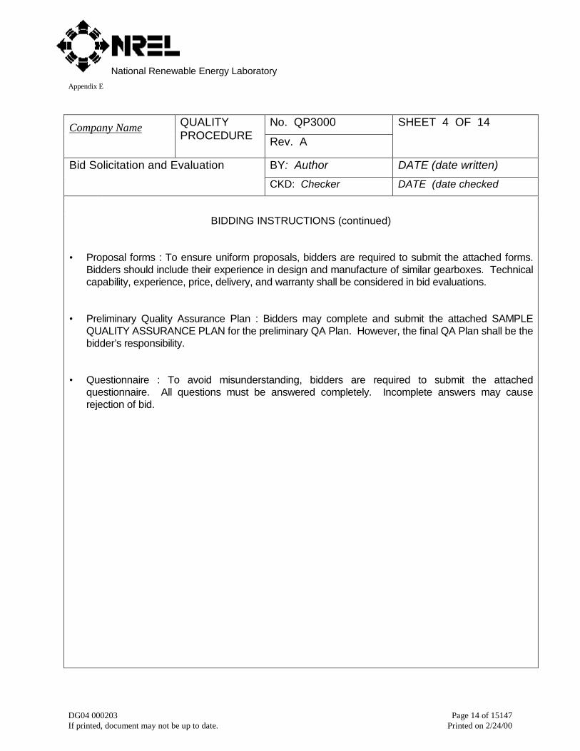
BIDDING INSTRUCTIONS (continued)
• Proposal forms : To ensure uniform proposals, bidders are required to submit the attached forms.Bidders should include their experience in design and manufacture of similar gearboxes. Technicalcapability, experience, price, delivery, and warranty shall be considered in bid evaluations.
• Preliminary Quality Assurance Plan : Bidders may complete and submit the attached SAMPLEQUALITY ASSURANCE PLAN for the preliminary QA Plan. However, the final QA Plan shall be thebidder’s responsibility.
• Questionnaire : To avoid misunderstanding, bidders are required to submit the attachedquestionnaire. All questions must be answered completely. Incomplete answers may causerejection of bid.
National Renewable Energy LaboratoryAppendix E
DG04 000203 Page 15 of 15147If printed, document may not be up to date. Printed on 2/24/00
No. QP3000Company Name QUALITYPROCEDURE Rev. A
SHEET 5 OF 14
BY: Author DATE (date written)Bid Solicitation and Evaluation
CKD: Checker DATE (date checked)
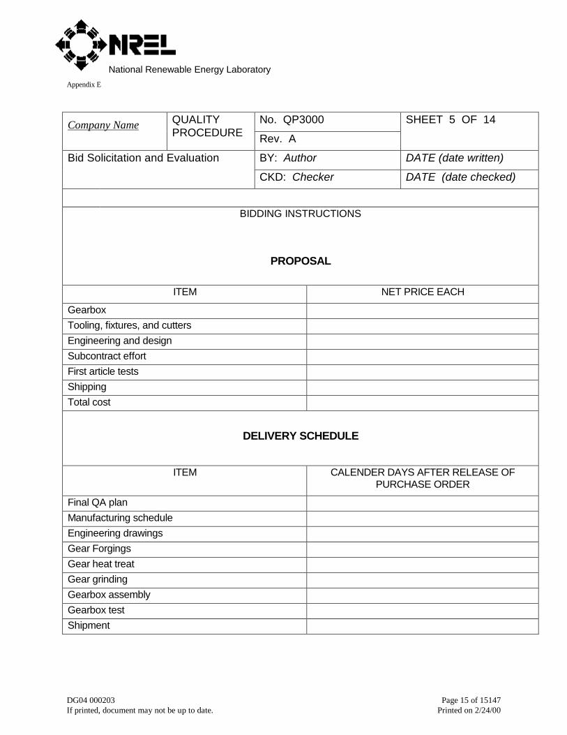
BIDDING INSTRUCTIONS
PROPOSAL
ITEM NET PRICE EACH
GearboxTooling, fixtures, and cuttersEngineering and designSubcontract effortFirst article testsShippingTotal cost
DELIVERY SCHEDULE
ITEM CALENDER DAYS AFTER RELEASE OFPURCHASE ORDER
Final QA planManufacturing scheduleEngineering drawingsGear ForgingsGear heat treatGear grindingGearbox assemblyGearbox testShipment

National Renewable Energy LaboratoryAppendix E
DG04 000203 Page 16 of 15147If printed, document may not be up to date. Printed on 2/24/00
No. QP3000Company Name QUALITYPROCEDURE Rev. A
SHEET 6 OF 14
BY: Author DATE (date written)Bid Solicitation and Evaluation
CKD: Checker DATE (date checked)
BID CERTIFICATION
I certify that this proposal, unless otherwise noted in Exceptions to Specification, meets all requirements ofProcurement Specification No. <number>.
Engineering Manager : Date : .
Quality Assurance Manager : Date : .
Purchasing Agent : Date : .
Bidder Company Name :
National Renewable Energy LaboratoryAppendix E
DG04 000203 Page 17 of 15147If printed, document may not be up to date. Printed on 2/24/00
No. QP3000Company Name QUALITYPROCEDURE Rev. A
SHEET 7 OF 14
BY: Author DATE (date written)Bid Solicitation and Evaluation
CKD: Checker DATE (date checked)
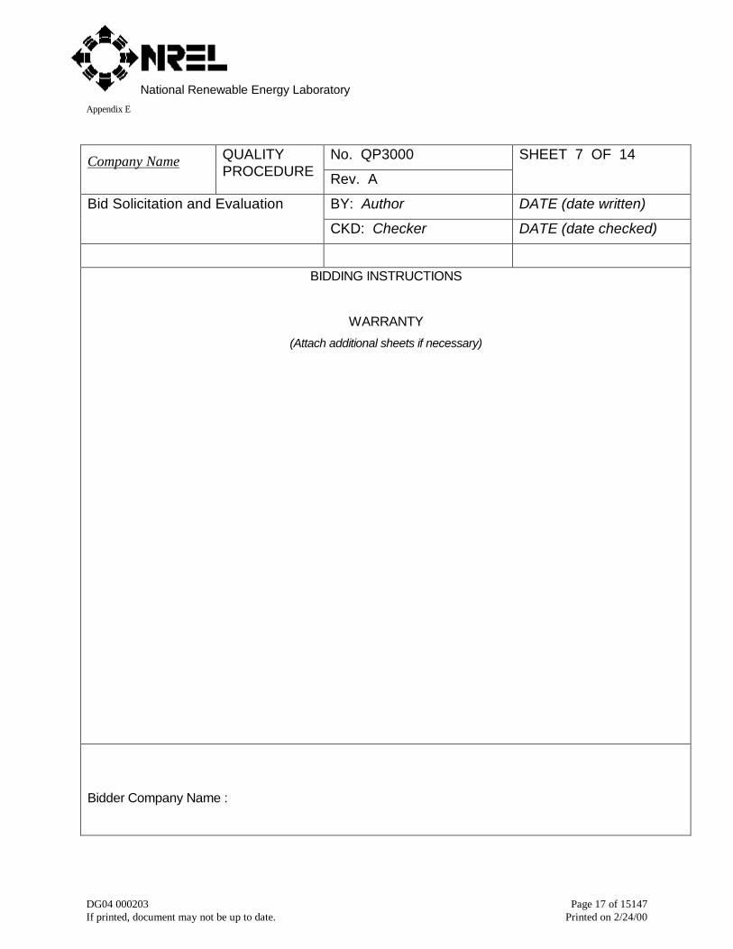
BIDDING INSTRUCTIONS
WARRANTY
(Attach additional sheets if necessary)
Bidder Company Name :
National Renewable Energy LaboratoryAppendix E
DG04 000203 Page 18 of 15147If printed, document may not be up to date. Printed on 2/24/00
No. QP3000Company Name QUALITYPROCEDURE Rev. A
SHEET 8 OF 14
BY: Author DATE (date written)Bid Solicitation and Evaluation
CKD: Checker DATE (date checked)
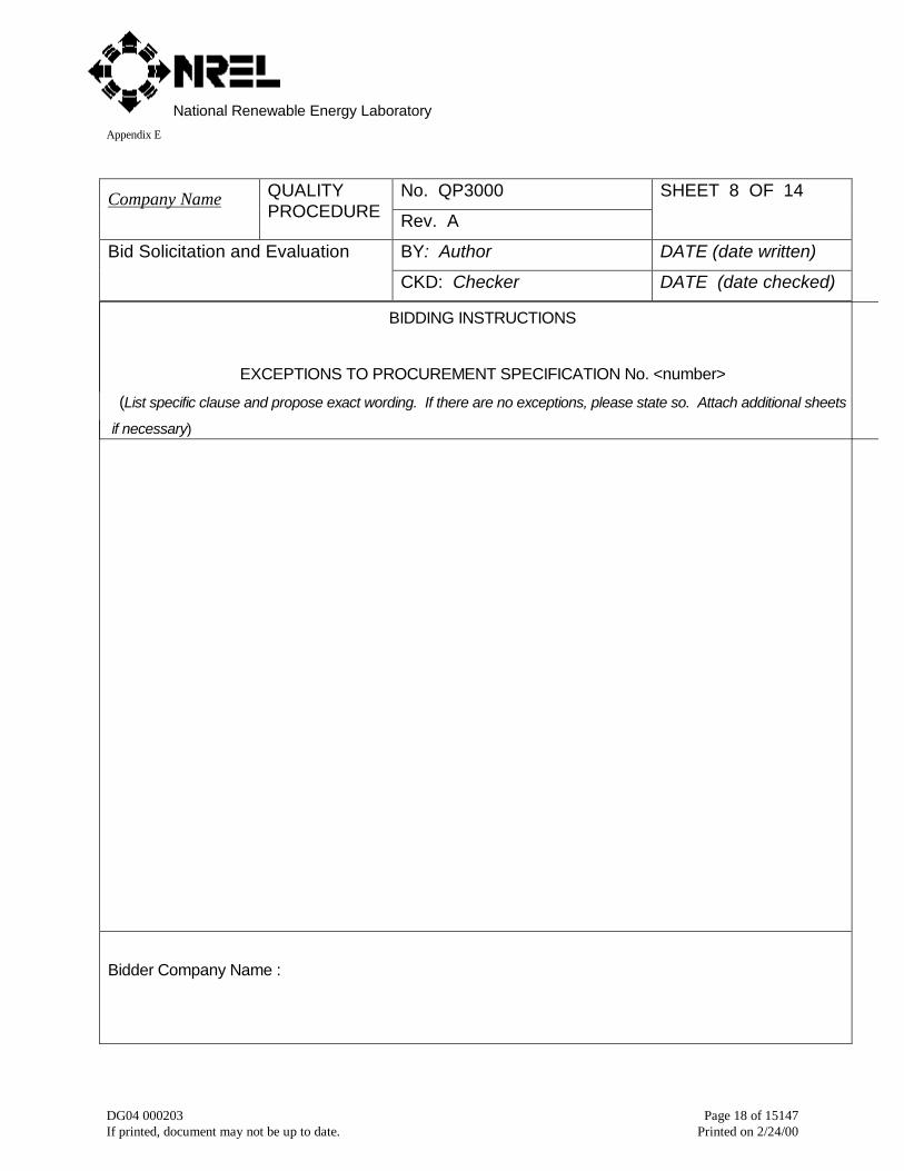
BIDDING INSTRUCTIONS
EXCEPTIONS TO PROCUREMENT SPECIFICATION No. <number>
(List specific clause and propose exact wording. If there are no exceptions, please state so. Attach additional sheets
if necessary)
Bidder Company Name :

National Renewable Energy LaboratoryAppendix E
DG04 000203 Page 19 of 15147If printed, document may not be up to date. Printed on 2/24/00
No. QP3000Company Name QUALITYPROCEDURE Rev. A
SHEET 9 OF 14
BY: Author DATE (date written)Bid Solicitation and Evaluation
CKD: Checker DATE (date checked)
BIDDING INSTRUCTIONS
SAMPLE QUALITY ASSURANCE PLAN
Page 1 of 4
LEGEND
H = Hold Point – Operation or procedure must be witnessed by purchaser’s representative beforemoving component to next operation.
W = Witness Point – Operation or procedure may be witnessed by purchaser’s representative if pur-chaser’s representative is present during manufacture.
D = Document Required – Quality assurance must provide certified copy of inspection or test report topurchaser’s representative.
Procurement Specification No. <number> Rev. <letter>
Activity H W D Procurement
Specification
Clause No.
Bidder Spec.
No.
Bidder Clause
No.
Bidder
Form
No.
Gear raw material X X
Process X X
Form X X
Chemistry X X
Grain size X X
Bidder Company Name :
National Renewable Energy LaboratoryAppendix E
DG04 000203 Page 20 of 15147If printed, document may not be up to date. Printed on 2/24/00
No. QP3000Company Name QUALITYPROCEDURE Rev. A
SHEET 10 OF 14
BY: Author DATE (date written)Bid Solicitation and Evaluation
CKD: Checker DATE (date checked)
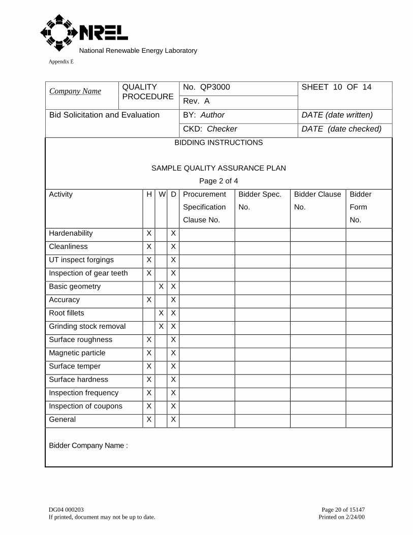
BIDDING INSTRUCTIONS
SAMPLE QUALITY ASSURANCE PLAN
Page 2 of 4
Activity H W D Procurement
Specification
Clause No.
Bidder Spec.
No.
Bidder Clause
No.
Bidder
Form
No.
Hardenability X X
Cleanliness X X
UT inspect forgings X X
Inspection of gear teeth X X
Basic geometry X X
Accuracy X X
Root fillets X X
Grinding stock removal X X
Surface roughness X X
Magnetic particle X X
Surface temper X X
Surface hardness X X
Inspection frequency X X
Inspection of coupons X X
General X X
Bidder Company Name :
National Renewable Energy LaboratoryAppendix E
DG04 000203 Page 21 of 15147If printed, document may not be up to date. Printed on 2/24/00
No. QP3000Company Name QUALITYPROCEDURE Rev. A
SHEET 11 OF 14
BY: Author DATE (date written)Bid Solicitation and Evaluation
CKD: Checker DATE (date checked)
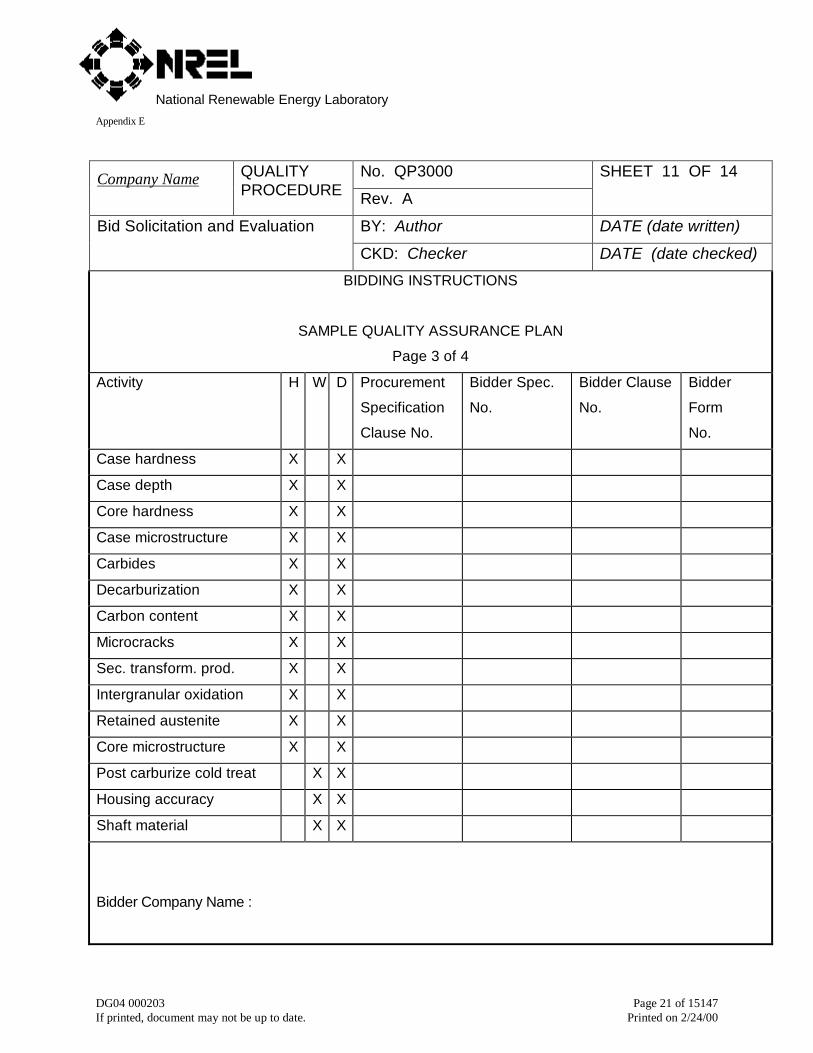
BIDDING INSTRUCTIONS
SAMPLE QUALITY ASSURANCE PLAN
Page 3 of 4
Activity H W D Procurement
Specification
Clause No.
Bidder Spec.
No.
Bidder Clause
No.
Bidder
Form
No.
Case hardness X X
Case depth X X
Core hardness X X
Case microstructure X X
Carbides X X
Decarburization X X
Carbon content X X
Microcracks X X
Sec. transform. prod. X X
Intergranular oxidation X X
Retained austenite X X
Core microstructure X X
Post carburize cold treat X X
Housing accuracy X X
Shaft material X X
Bidder Company Name :
National Renewable Energy LaboratoryAppendix E
DG04 000203 Page 22 of 15147If printed, document may not be up to date. Printed on 2/24/00
No. QP3000Company Name QUALITYPROCEDURE Rev. A
SHEET 12 OF 14
BY: Author DATE (date written)Bid Solicitation and Evaluation
CKD: Checker DATE (date checked)
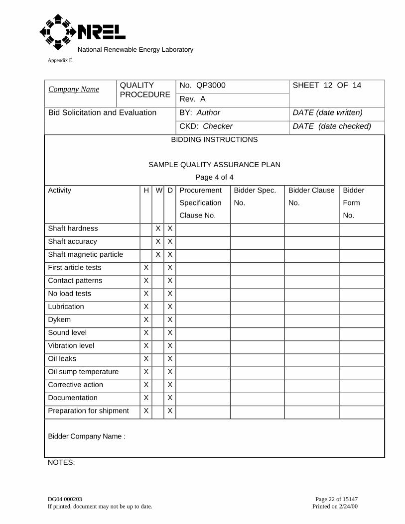
BIDDING INSTRUCTIONS
SAMPLE QUALITY ASSURANCE PLAN
Page 4 of 4
Activity H W D Procurement
Specification
Clause No.
Bidder Spec.
No.
Bidder Clause
No.
Bidder
Form
No.
Shaft hardness X X
Shaft accuracy X X
Shaft magnetic particle X X
First article tests X X
Contact patterns X X
No load tests X X
Lubrication X X
Dykem X X
Sound level X X
Vibration level X X
Oil leaks X X
Oil sump temperature X X
Corrective action X X
Documentation X X
Preparation for shipment X X
Bidder Company Name :
NOTES:
National Renewable Energy LaboratoryAppendix E
DG04 000203 Page 23 of 15147If printed, document may not be up to date. Printed on 2/24/00
No. QP3000Company Name QUALITYPROCEDURE Rev. A
SHEET 13 OF 14
BY: Author DATE (date written)Bid Solicitation and Evaluation
CKD: Checker DATE (date checked)
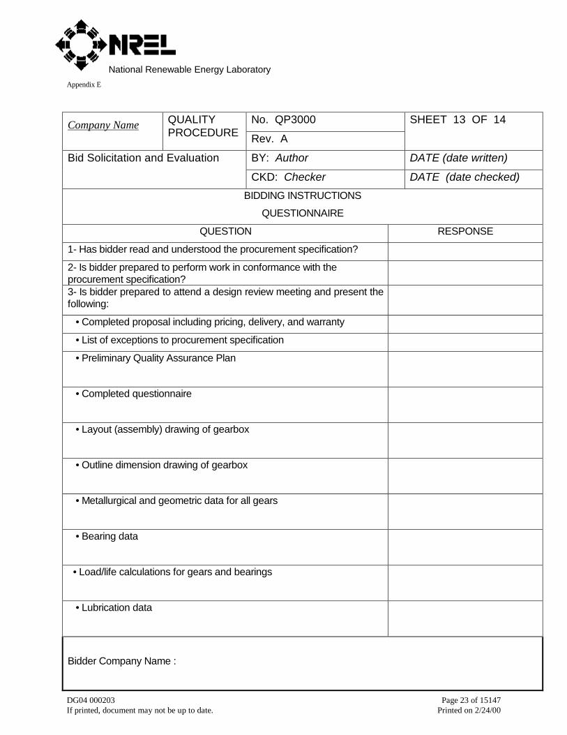
BIDDING INSTRUCTIONS
QUESTIONNAIRE
QUESTION RESPONSE
1- Has bidder read and understood the procurement specification?
2- Is bidder prepared to perform work in conformance with theprocurement specification?3- Is bidder prepared to attend a design review meeting and present thefollowing:
• Completed proposal including pricing, delivery, and warranty
• List of exceptions to procurement specification
• Preliminary Quality Assurance Plan
• Completed questionnaire
• Layout (assembly) drawing of gearbox
• Outline dimension drawing of gearbox
• Metallurgical and geometric data for all gears
• Bearing data
• Load/life calculations for gears and bearings
• Lubrication data
Bidder Company Name :
National Renewable Energy LaboratoryAppendix E
DG04 000203 Page 24 of 15147If printed, document may not be up to date. Printed on 2/24/00
No. QP3000Company Name QUALITYPROCEDURE Rev. A
SHEET 14 OF 14
BY: Author DATE (date written)Bid Solicitation and Evaluation
CKD: Checker DATE (date checked)
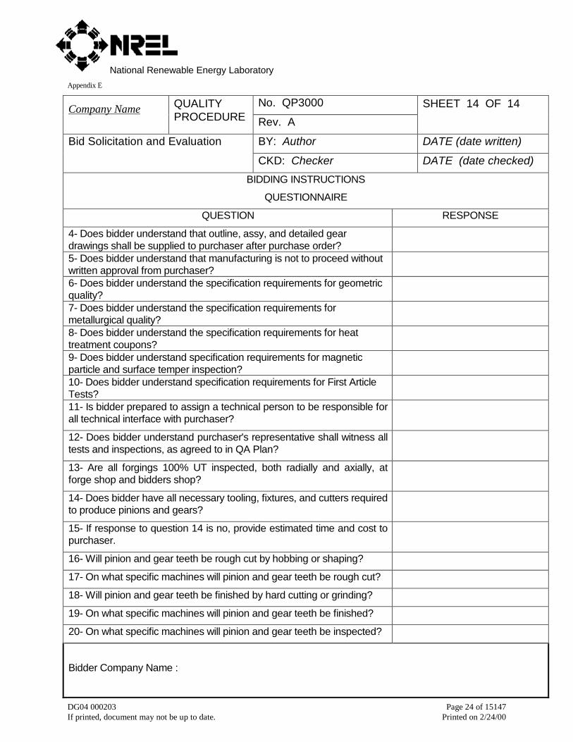
BIDDING INSTRUCTIONS
QUESTIONNAIRE
QUESTION RESPONSE
4- Does bidder understand that outline, assy, and detailed geardrawings shall be supplied to purchaser after purchase order?5- Does bidder understand that manufacturing is not to proceed withoutwritten approval from purchaser?6- Does bidder understand the specification requirements for geometricquality?7- Does bidder understand the specification requirements formetallurgical quality?8- Does bidder understand the specification requirements for heattreatment coupons?9- Does bidder understand specification requirements for magneticparticle and surface temper inspection?10- Does bidder understand specification requirements for First ArticleTests?11- Is bidder prepared to assign a technical person to be responsible forall technical interface with purchaser?
12- Does bidder understand purchaser's representative shall witness alltests and inspections, as agreed to in QA Plan?
13- Are all forgings 100% UT inspected, both radially and axially, atforge shop and bidders shop?
14- Does bidder have all necessary tooling, fixtures, and cutters requiredto produce pinions and gears?
15- If response to question 14 is no, provide estimated time and cost topurchaser.
16- Will pinion and gear teeth be rough cut by hobbing or shaping?
17- On what specific machines will pinion and gear teeth be rough cut?
18- Will pinion and gear teeth be finished by hard cutting or grinding?
19- On what specific machines will pinion and gear teeth be finished?
20- On what specific machines will pinion and gear teeth be inspected?
Bidder Company Name :
National Renewable Energy LaboratoryAppendix E
DG04 000203 Page 25 of 15147If printed, document may not be up to date. Printed on 2/24/00
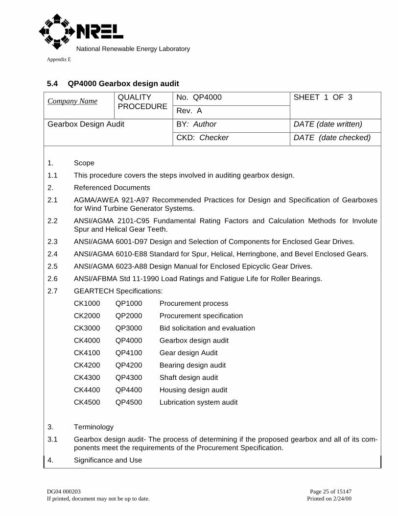
5.4 QP4000 Gearbox design audit
No. QP4000Company Name QUALITYPROCEDURE Rev. A
SHEET 1 OF 3
BY: Author DATE (date written)Gearbox Design Audit
CKD: Checker DATE (date checked)
1. Scope
1.1 This procedure covers the steps involved in auditing gearbox design.
2. Referenced Documents
2.1 AGMA/AWEA 921-A97 Recommended Practices for Design and Specification of Gearboxesfor Wind Turbine Generator Systems.
2.2 ANSI/AGMA 2101-C95 Fundamental Rating Factors and Calculation Methods for InvoluteSpur and Helical Gear Teeth.
2.3 ANSI/AGMA 6001-D97 Design and Selection of Components for Enclosed Gear Drives.
2.4 ANSI/AGMA 6010-E88 Standard for Spur, Helical, Herringbone, and Bevel Enclosed Gears.
2.5 ANSI/AGMA 6023-A88 Design Manual for Enclosed Epicyclic Gear Drives.
2.6 ANSI/AFBMA Std 11-1990 Load Ratings and Fatigue Life for Roller Bearings.
2.7 GEARTECH Specifications:
CK1000 QP1000 Procurement process
CK2000 QP2000 Procurement specification
CK3000 QP3000 Bid solicitation and evaluation
CK4000 QP4000 Gearbox design audit
CK4100 QP4100 Gear design Audit
CK4200 QP4200 Bearing design audit
CK4300 QP4300 Shaft design audit
CK4400 QP4400 Housing design audit
CK4500 QP4500 Lubrication system audit
3. Terminology
3.1 Gearbox design audit- The process of determining if the proposed gearbox and all of its com-ponents meet the requirements of the Procurement Specification.
4. Significance and Use
National Renewable Energy LaboratoryAppendix E
DG04 000203 Page 26 of 15147If printed, document may not be up to date. Printed on 2/24/00
No. QP4000Company Name QUALITYPROCEDURE Rev. A
SHEET 2 OF 3
BY: Author DATE (date written)Gearbox Design Audit
CKD: Checker DATE (date checked)
4.1 Significance and Use- A complete gearbox design audit including but not limited to gear detaildrawings, assembly drawings and layout drawings is necessary to ensure the design meetsthe requirements of the procurement specification and has adequate capacity for the applica-tion.
5. Procedure
5.1. Proposal data- The proposal shall include all data listed in CK4000.
5.2 Gear Calculations- Gear calculations shall be performed per Section 4.3.1, of AGMA/AWEA921-A97, Gear Life Rating, and QP4100.
5.3 Gearbox thermal rating- Gearbox thermal rating shall be performed per Section 4.3.2, ofAGMA/AWEA 921-A97, Gearbox Thermal Rating, and QP4100.
5.4 Bearing calculations- Bearing calculations shall be performed per Section 4.3.3, ofAGMA/AWEA 921-A97, Bearing Life Calculations, and QP4200.
5.5 Shaft Calculations- Shaft Calculations shall be performed per Section 4.3.4, of AGMA/AWEA921-A97, Shaft Life Ratings, and QP4300.
5.6 Housing calculations- Housing calculations shall be performed as per Section 4.3.5, ofAGMA/AWEA 921-A97, Housing, and QP4400.
5.7 Lubrication system- The lubrication system shall be audited for conformance to Section 4.8 ofAGMA/AWEA 921-A97, Lubrication System, and QP4500.
5.8 Maintainability- The gearbox and lubrication system shall be audited for conformance to AnnexE of AGMA/AWEA 921-A97, Operation and Maintenance, and the procurement specification.
6. Interpretation of Results
6.1 Specification conformance- The results of the gearbox design audit shall be compared to therequirements of the procurement specification for the following categories:
• Design features
• Load capacity
• Lubrication system
• Maintainability
7. Acceptance Criteria
7.1 Design features- Gearbox design features shall meet the requirements of AGMA/AWEA 921-A97 and the Procurement Specification.
National Renewable Energy LaboratoryAppendix E
DG04 000203 Page 27 of 15147If printed, document may not be up to date. Printed on 2/24/00
No. QP4000Company Name QUALITY PRO-CEDURE Rev. A
SHEET 3 OF 3
BY: Author DATE (date written)Gearbox Design Audit
CKD: Checker DATE (date checked)
7.2 Load capacity- Gearbox components shall have load capacities meeting the requirements ofthe following Quality Procedures:
1.1.1.1.4 QP4100 Gear design auditQP4200 Bearing design audit
QP4300 Shaft design audit
1.1.1.1.5 QP4400 Housing design audit7.3 Lubrication System- The lubrication system shall meet the requirements of QP4500.
7.4 Maintainability- Gearbox maintainability shall meet the requirements of AGMA/AWEA 921-A97 and the Procurement Specification.
7.5 Gearbox design audit- The gearbox design shall meet the requirements of the ProcurementSpecification.
8. Report
8.1 The report shall include the following:
8.1.1 Summary of gear life ratings and thermal ratings,
8.1.4 Summary of housing calculations,
8.1.5 Summary of lubrication system audit,
8.1.6 Summary of maintainability audit, and
8.1.7 Recommendations for revisions to engineering specifications required for conformance tothe procurement specification.
National Renewable Energy LaboratoryAppendix E
DG04 000203 Page 28 of 15147If printed, document may not be up to date. Printed on 2/24/00
No. QP4100Company Name QUALITYPROCEDURE Rev. A
SHEET 1 OF 6
BY: Author DATE (date written)Gear Design Audit
CKD: Checker DATE (date checked)
1. Scope
1.1 This procedure covers rating analysis methods for determining Hertzian and bending fa-tigue lives, and probability of scuffing per AGMA/AWEA 921-A97 and AGMA 2001-C95. Italso includes guidelines for avoiding micropitting.
2. Referenced Documents
2.1 AGMA/AWEA 921-A97 Recommended Practices for Design and Specification of Gear-boxes for Wind Turbine Generator Systems.
2.2 ANSI/AGMA 2000-A88 Gear Classification and Inspection Handbook.
2.3 ANSI/AGMA 2001-C95 Fundamental Rating Factors and Calculation Methods for InvoluteSpur and Helical Gear Teeth.
2.4 GEARTECH Specifications:
CK1000 QP1000 Procurement process
CK2000 QP2000 Procurement specification
CK3000 QP3000 Bid solicitation and evaluation
CK4000 QP4000 Gearbox design audit
CK4100 QP4100 Gear design audit
CK5000 QP5000 Quality assessment
CK6000 QP6000 Quality assurance plan
CK7000 QP7000 Manufacturing schedule
CK8000 QP8000 Manufacturing audit
CK8100 QP8100 Gear raw material
CK8200 QP8200 Gear tooth cutting
CK8300 QP8300 Heat treatment of carburized gears
CK8400 QP8400 Gear tooth grinding
CK8500 QP8500 Gear tooth inspection
National Renewable Energy LaboratoryAppendix E
DG04 000203 Page 29 of 15147If printed, document may not be up to date. Printed on 2/24/00
No. QP4100Company Name QUALITYPROCEDURE Rev. A
SHEET 2 OF 6
BY: Author DATE (date written)Gear Design Audit
CKD: Checker DATE (date checked)
3. Terminology
3.1 Definitions- See referenced documents for definition of terms.
3.2 Load distribution factor- The ratio of maximum load intensity to mean load intensity. SeeANSI/AGMA 2001-C95 for factors influencing load distribution.
3.3 Dynamic factor- The ratio of dynamic gear tooth load to static gear tooth load. SeeANSI/AGMA 2001-C95 for factors influencing dynamic load.
3.4 Contact temperature- The sum of the gear tooth and flash temperatures. The maximumvalue along the line of action is compared to the scuffing temperature to assess risk ofscuffing.
3.5 Gear tooth temperature- The equilibrium temperature of the surface of gear teeth beforethey enter the contact zone. Tooth temperature may be significantly higher than the tem-perature of oil supplied to the gear mesh.
3.6 Flash temperature- The instantaneous rise in gear tooth surface temperature at a givenpoint along the line of action resulting from combined effects of gear tooth geometry, load,friction, velocity and material properties.
3.7 Scuffing temperature- The contact temperature at which scuffing is likely to occur with thechosen combination of lubricant and gear materials. The mean scuffing temperature is thetemperature at which there is a 50% chance scuffing will occur.
3.8 Lubricant dynamic viscosity- The viscosity used in lubricant film thickness calculations isdynamic viscosity measured in units of centipoise (cP). ANSI/AGMA 2001-C95 Annex Agives values of dynamic viscosity versus gear tooth temperature.
3.9 Lubricant pressure-viscosity coefficient- Calculations of lubricant film thickness require thepressure-viscosity coefficient, which characterizes exponential increase in viscosity withpressure. ANSI/AGMA 2001-C95 Annex A gives values of pressure- viscosity coefficientversus gear tooth temperature.
3.10 Lubricant micropitting resistance- A standard test used to determine micropitting resistancein accordance with FVA-Information Sheet “Micropitting,” No. 54/7 (July 1993) For-schungsvereinigung Antriebstechnik e.V., Lyoner Strasse 18, D-60528 Frankfurt/Main.
3.11 Aspect ratio- The ratio of pinion face to pinion operating pitch diameter.
3.12 Transverse contact ratio- The ratio of the angle of action to angular pitch. It is a measureof the number of teeth in contact and smoothness of gear tooth meshing.
3.13 Axial contact ratio- The ratio of active face width to axial pitch. It is a measure of the num-ber of teeth in contact and smoothness of gear tooth meshing.
National Renewable Energy LaboratoryAppendix E
DG04 000203 Page 30 of 15147If printed, document may not be up to date. Printed on 2/24/00
No. QP4100Company Name QUALITYPROCEDURE Rev. A
SHEET 3 OF 6
BY: Author DATE (date written)Gear Design Audit
CKD: Checker DATE (date checked)
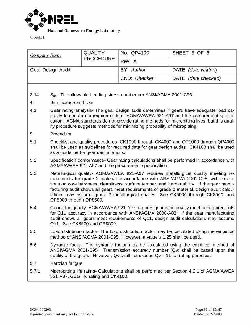
3.14 Sat – The allowable bending stress number per ANSI/AGMA 2001-C95.
4. Significance and Use
4.1 Gear rating analysis- The gear design audit determines if gears have adequate load ca-pacity to conform to requirements of AGMA/AWEA 921-A97 and the procurement specifi-cation. AGMA standards do not provide rating methods for micropitting lives, but this qual-ity procedure suggests methods for minimizing probability of micropitting.
5. Procedure
5.1 Checklist and quality procedures- CK1000 through CK4000 and QP1000 through QP4000shall be used as guidelines for required data for gear design audits. CK4100 shall be usedas a guideline for gear design audits.
5.2 Specification conformance- Gear rating calculations shall be performed in accordance withAGMA/AWEA 921-A97 and the procurement specification.
5.3 Metallurgical quality- AGMA/AWEA 921-A97 requires metallurgical quality meeting re-quirements for grade 2 material in accordance with ANSI/AGMA 2001-C95, with excep-tions on core hardness, cleanliness, surface temper, and hardenability. If the gear manu-facturing audit shows all gears meet requirements of grade 2 material, design audit calcu-lations may assume grade 2 metallurgical quality. See CK5000 through CK8500, andQP5000 through QP8500.
5.4 Geometric quality- AGMA/AWEA 921-A97 requires geometric quality meeting requirementsfor Q11 accuracy in accordance with ANSI/AGMA 2000-A88. If the gear manufacturingaudit shows all gears meet requirements of Q11, design audit calculations may assumeQ11. See CK8500 and QP8500.
5.5 Load distribution factor- The load distribution factor may be calculated using the empiricalmethod of ANSI/AGMA 2001-C95. However, a value ≥ 1.25 shall be used.
5.6 Dynamic factor- The dynamic factor may be calculated using the empirical method ofANSI/AGMA 2001-C95. Transmission accuracy number (Qv) shall be based upon thequality of the gears. However, Qv shall not exceed Qv = 11 for rating purposes.
5.7 Hertzian fatigue
5.7.1 Macropitting life rating- Calculations shall be performed per Section 4.3.1 of AGMA/AWEA921-A97, Gear life rating and CK4100.
National Renewable Energy LaboratoryAppendix E
DG04 000203 Page 31 of 15147If printed, document may not be up to date. Printed on 2/24/00
No. QP4100Company Name QUALITYPROCEDURE Rev. A
SHEET 4 OF 6
BY: Author DATE (date written)Gear Design Audit
CKD: Checker DATE (date checked)
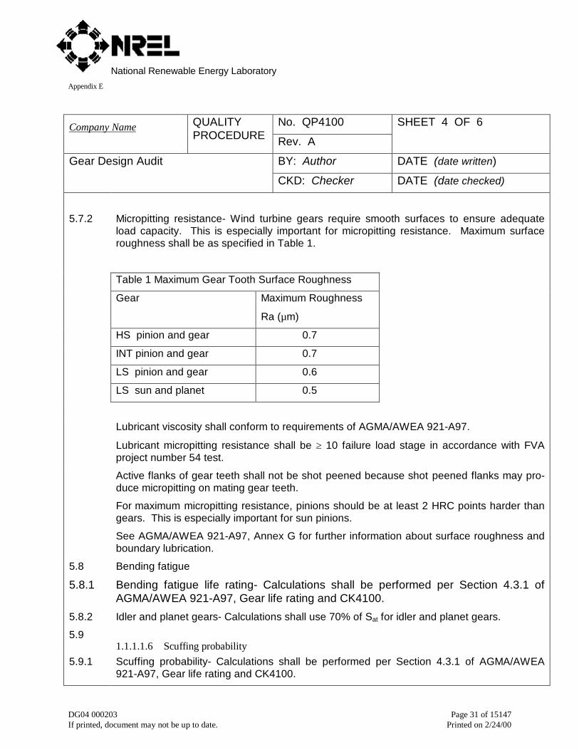
5.7.2 Micropitting resistance- Wind turbine gears require smooth surfaces to ensure adequateload capacity. This is especially important for micropitting resistance. Maximum surfaceroughness shall be as specified in Table 1.
Table 1 Maximum Gear Tooth Surface Roughness
Gear Maximum Roughness
Ra (µm)
HS pinion and gear 0.7
INT pinion and gear 0.7
LS pinion and gear 0.6
LS sun and planet 0.5
Lubricant viscosity shall conform to requirements of AGMA/AWEA 921-A97.
Lubricant micropitting resistance shall be ≥ 10 failure load stage in accordance with FVAproject number 54 test.
Active flanks of gear teeth shall not be shot peened because shot peened flanks may pro-duce micropitting on mating gear teeth.
For maximum micropitting resistance, pinions should be at least 2 HRC points harder thangears. This is especially important for sun pinions.
See AGMA/AWEA 921-A97, Annex G for further information about surface roughness andboundary lubrication.
5.8 Bending fatigue
5.8.1 Bending fatigue life rating- Calculations shall be performed per Section 4.3.1 ofAGMA/AWEA 921-A97, Gear life rating and CK4100.
5.8.2 Idler and planet gears- Calculations shall use 70% of Sat for idler and planet gears.
5.91.1.1.1.6 Scuffing probability
5.9.1 Scuffing probability- Calculations shall be performed per Section 4.3.1 of AGMA/AWEA921-A97, Gear life rating and CK4100.
National Renewable Energy LaboratoryAppendix E
DG04 000203 Page 32 of 15147If printed, document may not be up to date. Printed on 2/24/00
No. QP4100Company Name QUALITYPROCEDURE Rev. A
SHEET 5 OF 6
BY: Author DATE (date written)Gear Design Audit
CKD: Checker DATE (date checked)
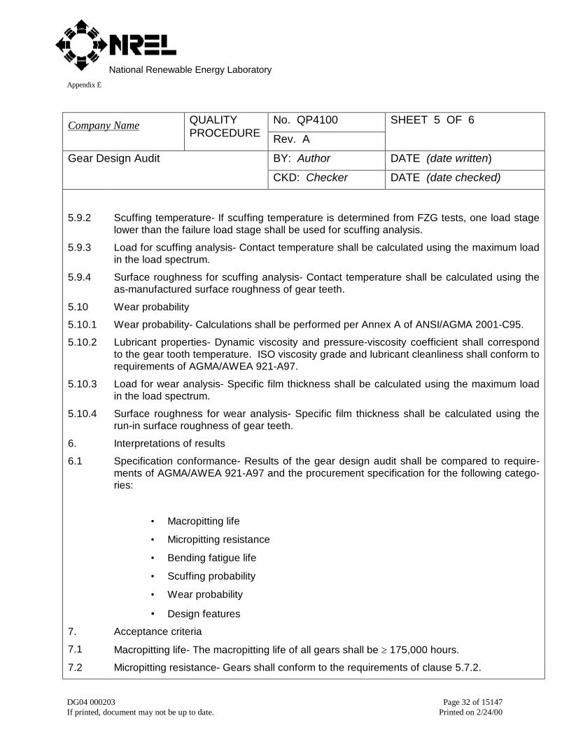
5.9.2 Scuffing temperature- If scuffing temperature is determined from FZG tests, one load stagelower than the failure load stage shall be used for scuffing analysis.
5.9.3 Load for scuffing analysis- Contact temperature shall be calculated using the maximum loadin the load spectrum.
5.9.4 Surface roughness for scuffing analysis- Contact temperature shall be calculated using theas-manufactured surface roughness of gear teeth.
5.10 Wear probability
5.10.1 Wear probability- Calculations shall be performed per Annex A of ANSI/AGMA 2001-C95.
5.10.2 Lubricant properties- Dynamic viscosity and pressure-viscosity coefficient shall correspondto the gear tooth temperature. ISO viscosity grade and lubricant cleanliness shall conform torequirements of AGMA/AWEA 921-A97.
5.10.3 Load for wear analysis- Specific film thickness shall be calculated using the maximum loadin the load spectrum.
5.10.4 Surface roughness for wear analysis- Specific film thickness shall be calculated using therun-in surface roughness of gear teeth.
6. Interpretations of results
6.1 Specification conformance- Results of the gear design audit shall be compared to require-ments of AGMA/AWEA 921-A97 and the procurement specification for the following catego-ries:
• Macropitting life
• Micropitting resistance
• Bending fatigue life
• Scuffing probability
• Wear probability
• Design features
7. Acceptance criteria
7.1 Macropitting life- The macropitting life of all gears shall be ≥ 175,000 hours.
7.2 Micropitting resistance- Gears shall conform to the requirements of clause 5.7.2.
National Renewable Energy LaboratoryAppendix E
DG04 000203 Page 33 of 15147If printed, document may not be up to date. Printed on 2/24/00
No. QP4100Company Name QUALITYPROCEDURE Rev. A
SHEET 6 OF 6
BY: Author DATE (date written)Gear Design Audit
CKD: Checker DATE (date checked)
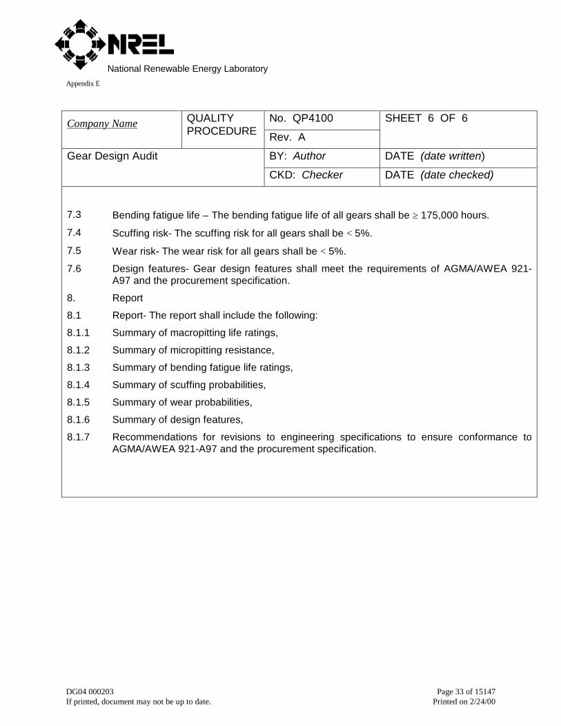
7.3 Bending fatigue life – The bending fatigue life of all gears shall be ≥ 175,000 hours.
7.4 Scuffing risk- The scuffing risk for all gears shall be < 5%.
7.5 Wear risk- The wear risk for all gears shall be < 5%.
7.6 Design features- Gear design features shall meet the requirements of AGMA/AWEA 921-A97 and the procurement specification.
8. Report
8.1 Report- The report shall include the following:
8.1.1 Summary of macropitting life ratings,
8.1.2 Summary of micropitting resistance,
8.1.3 Summary of bending fatigue life ratings,
8.1.4 Summary of scuffing probabilities,
8.1.5 Summary of wear probabilities,
8.1.6 Summary of design features,
8.1.7 Recommendations for revisions to engineering specifications to ensure conformance toAGMA/AWEA 921-A97 and the procurement specification.

National Renewable Energy LaboratoryAppendix E
DG04 000203 Page 34 of 15147If printed, document may not be up to date. Printed on 2/24/00
No. QP4200Company Name QUALITYPROCEDURE Rev. A
SHEET 1 OF 5
BY: Author DATE (date written)Bearing Design Audit
CKD: Checker DATE (date checked)
1. Scope
1.1 This procedure covers rating analysis methods for determining load ratings and fatigue life ofroller bearings per AGMA/AWEA 921-A97 and ANSI/AFBMA Std. 11-1990.
2. Referenced Documents
2.1 AGMA/AWEA 921-A97 Recommended Practices for Design and Specification of Gearboxesfor Wind Turbine Generator Systems.
2.2 ANSI/AFBMA Std. 11-1990, Load Ratings and Fatigue Life of Roller Bearings.
2.3 ISO/DIS 4406 (SAE J1165), Hydraulic Fluid Power-fluids-method for coding level of con-tamination by solid particles.
2.4 GEARTECH Specifications:
CK1000 QP1000 Procurement process
CK2000 QP2000 Procurement specification
CK3000 QP3000 Bid solicitation and evaluation
CK4000 QP4000 Gearbox design audit
CK4200 QP4200 Bearing design audit
CK5000 QP5000 Quality assessment
CK6000 QP6000 Quality assurance plan
CK7000 QP7000 Manufacturing schedule
CK8000 QP8000 Manufacturing audit
3. Terminology
3.1 Definitions- See referenced documents for definition of terms.
3.2 L1 life- Adjusted life for 1% failure probability.
3.3 L10 life- Nominal life for 10% failure probability.
3.4 a1- Life adjustment factor for failure probability.
3.5 a23- Life adjustment factor for material, bearing type, lubrication, and cleanliness.
3.6 Lubricant cleanliness- ISO/DIS 4406 cleanliness code.
National Renewable Energy LaboratoryAppendix E
DG04 000203 Page 35 of 15147If printed, document may not be up to date. Printed on 2/24/00
No. QP4200Company Name QUALITYPROCEDURE Rev. A
SHEET 2 OF 5
BY: Author DATE (date written)Bearing Design Audit
CKD: Checker DATE (date checked)
4. Significance and Use
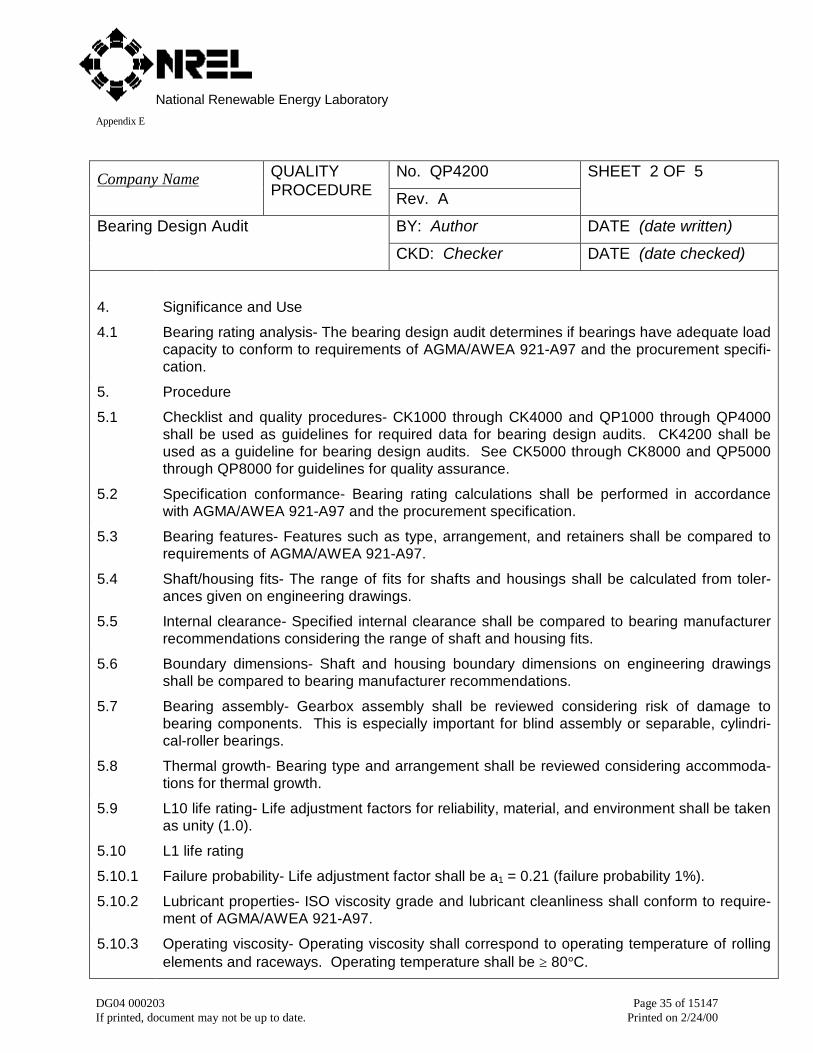
4.1 Bearing rating analysis- The bearing design audit determines if bearings have adequate loadcapacity to conform to requirements of AGMA/AWEA 921-A97 and the procurement specifi-cation.
5. Procedure
5.1 Checklist and quality procedures- CK1000 through CK4000 and QP1000 through QP4000shall be used as guidelines for required data for bearing design audits. CK4200 shall beused as a guideline for bearing design audits. See CK5000 through CK8000 and QP5000through QP8000 for guidelines for quality assurance.
5.2 Specification conformance- Bearing rating calculations shall be performed in accordancewith AGMA/AWEA 921-A97 and the procurement specification.
5.3 Bearing features- Features such as type, arrangement, and retainers shall be compared torequirements of AGMA/AWEA 921-A97.
5.4 Shaft/housing fits- The range of fits for shafts and housings shall be calculated from toler-ances given on engineering drawings.
5.5 Internal clearance- Specified internal clearance shall be compared to bearing manufacturerrecommendations considering the range of shaft and housing fits.
5.6 Boundary dimensions- Shaft and housing boundary dimensions on engineering drawingsshall be compared to bearing manufacturer recommendations.
5.7 Bearing assembly- Gearbox assembly shall be reviewed considering risk of damage tobearing components. This is especially important for blind assembly or separable, cylindri-cal-roller bearings.
5.8 Thermal growth- Bearing type and arrangement shall be reviewed considering accommoda-tions for thermal growth.
5.9 L10 life rating- Life adjustment factors for reliability, material, and environment shall be takenas unity (1.0).
5.10 L1 life rating
5.10.1 Failure probability- Life adjustment factor shall be a1 = 0.21 (failure probability 1%).
5.10.2 Lubricant properties- ISO viscosity grade and lubricant cleanliness shall conform to require-ment of AGMA/AWEA 921-A97.
5.10.3 Operating viscosity- Operating viscosity shall correspond to operating temperature of rollingelements and raceways. Operating temperature shall be ≥ 80°C.
National Renewable Energy LaboratoryAppendix E
DG04 000203 Page 36 of 15147If printed, document may not be up to date. Printed on 2/24/00
No. QP4200Company Name QUALITYPROCEDURE Rev. A
SHEET 3 OF 5
BY: Author DATE (date written)Bearing Design Audit
CKD: Checker DATE (date checked)
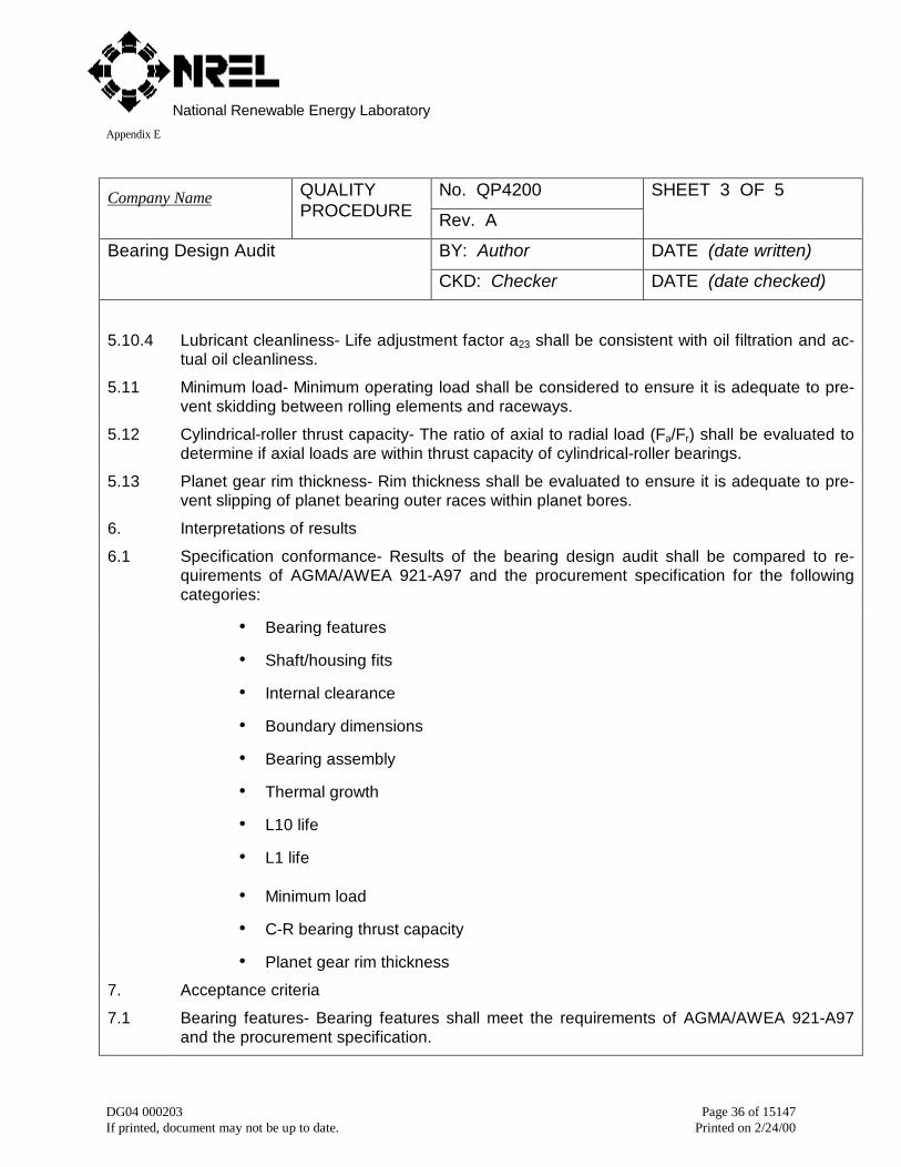
5.10.4 Lubricant cleanliness- Life adjustment factor a23 shall be consistent with oil filtration and ac-tual oil cleanliness.
5.11 Minimum load- Minimum operating load shall be considered to ensure it is adequate to pre-vent skidding between rolling elements and raceways.
5.12 Cylindrical-roller thrust capacity- The ratio of axial to radial load (Fa/Fr) shall be evaluated todetermine if axial loads are within thrust capacity of cylindrical-roller bearings.
5.13 Planet gear rim thickness- Rim thickness shall be evaluated to ensure it is adequate to pre-vent slipping of planet bearing outer races within planet bores.
6. Interpretations of results
6.1 Specification conformance- Results of the bearing design audit shall be compared to re-quirements of AGMA/AWEA 921-A97 and the procurement specification for the followingcategories:
• Bearing features
• Shaft/housing fits
• Internal clearance
• Boundary dimensions
• Bearing assembly
• Thermal growth
• L10 life
• L1 life
• Minimum load
• C-R bearing thrust capacity
• Planet gear rim thickness
7. Acceptance criteria
7.1 Bearing features- Bearing features shall meet the requirements of AGMA/AWEA 921-A97and the procurement specification.
National Renewable Energy LaboratoryAppendix E
DG04 000203 Page 37 of 15147If printed, document may not be up to date. Printed on 2/24/00
No. QP4200Company Name QUALITYPROCEDURE Rev. A
SHEET 4 OF 5
BY: Author DATE (date written)Bearing Design Audit
CKD: Checker DATE (date checked)
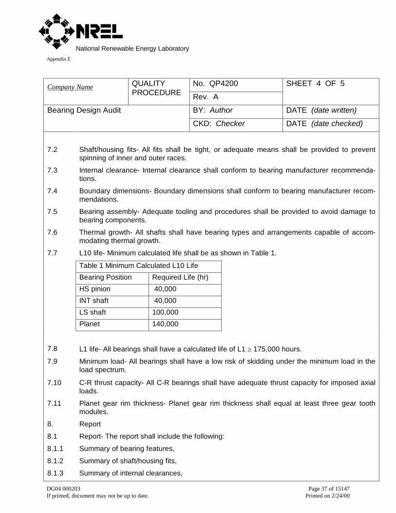
7.2 Shaft/housing fits- All fits shall be tight, or adequate means shall be provided to preventspinning of inner and outer races.
7.3 Internal clearance- Internal clearance shall conform to bearing manufacturer recommenda-tions.
7.4 Boundary dimensions- Boundary dimensions shall conform to bearing manufacturer recom-mendations.
7.5 Bearing assembly- Adequate tooling and procedures shall be provided to avoid damage tobearing components.
7.6 Thermal growth- All shafts shall have bearing types and arrangements capable of accom-modating thermal growth.
7.7 L10 life- Minimum calculated life shall be as shown in Table 1.
Table 1 Minimum Calculated L10 Life
Bearing Position Required Life (hr)
HS pinion 40,000
INT shaft 40,000
LS shaft 100,000
Planet 140,000
7.8 L1 life- All bearings shall have a calculated life of L1 ≥ 175,000 hours.
7.9 Minimum load- All bearings shall have a low risk of skidding under the minimum load in theload spectrum.
7.10 C-R thrust capacity- All C-R bearings shall have adequate thrust capacity for imposed axialloads.
7.11 Planet gear rim thickness- Planet gear rim thickness shall equal at least three gear toothmodules.
8. Report
8.1 Report- The report shall include the following:
8.1.1 Summary of bearing features,
8.1.2 Summary of shaft/housing fits,
8.1.3 Summary of internal clearances,

National Renewable Energy LaboratoryAppendix E
DG04 000203 Page 38 of 15147If printed, document may not be up to date. Printed on 2/24/00
No. QP4200Company Name QUALITYPROCEDURE Rev. A
SHEET 5 OF 5
BY: Author DATE (date written)Bearing Design Audit
CKD: Checker DATE (date checked)
8.1.4 Summary of boundary dimensions,
8.1.5 Summary of bearing assembly,
8.1.6 Summary of thermal growth,
8.1.7 Summary of L10 life,
8.1.8 Summary of L1 life,
8.1.9 Summary of minimum load,
8.1.10 Summary of C-R bearing thrust capacity,
8.1.11 Summary of planet gear rim thickness,
8.1.12 Recommendations for revisions to engineering specifications to ensure conformance toAGMA/AWEA 921-A97 and the procurement specification.
National Renewable Energy LaboratoryAppendix E
DG04 000203 Page 39 of 15147If printed, document may not be up to date. Printed on 2/24/00
No. QP4300Company Name QUALITYPROCEDURE Rev. A
SHEET 1 OF 4
BY: Author DATE (date written)Shaft Design Audit
CKD: Checker DATE (date checked)
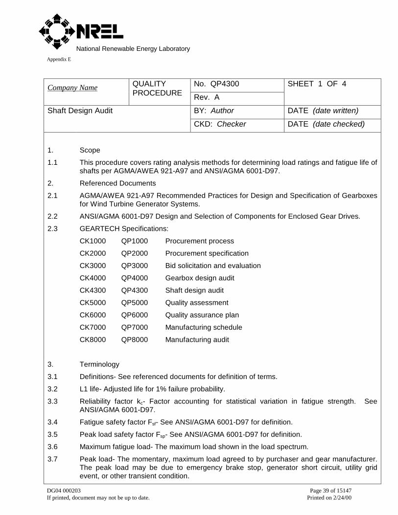
1. Scope
1.1 This procedure covers rating analysis methods for determining load ratings and fatigue life ofshafts per AGMA/AWEA 921-A97 and ANSI/AGMA 6001-D97.
2. Referenced Documents
2.1 AGMA/AWEA 921-A97 Recommended Practices for Design and Specification of Gearboxesfor Wind Turbine Generator Systems.
2.2 ANSI/AGMA 6001-D97 Design and Selection of Components for Enclosed Gear Drives.
2.3 GEARTECH Specifications:
CK1000 QP1000 Procurement process
CK2000 QP2000 Procurement specification
CK3000 QP3000 Bid solicitation and evaluation
CK4000 QP4000 Gearbox design audit
CK4300 QP4300 Shaft design audit
CK5000 QP5000 Quality assessment
CK6000 QP6000 Quality assurance plan
CK7000 QP7000 Manufacturing schedule
CK8000 QP8000 Manufacturing audit
3. Terminology
3.1 Definitions- See referenced documents for definition of terms.
3.2 L1 life- Adjusted life for 1% failure probability.
3.3 Reliability factor kc- Factor accounting for statistical variation in fatigue strength. SeeANSI/AGMA 6001-D97.
3.4 Fatigue safety factor Fsf- See ANSI/AGMA 6001-D97 for definition.
3.5 Peak load safety factor Fsp- See ANSI/AGMA 6001-D97 for definition.
3.6 Maximum fatigue load- The maximum load shown in the load spectrum.
3.7 Peak load- The momentary, maximum load agreed to by purchaser and gear manufacturer.The peak load may be due to emergency brake stop, generator short circuit, utility gridevent, or other transient condition.
National Renewable Energy LaboratoryAppendix E
DG04 000203 Page 40 of 15147If printed, document may not be up to date. Printed on 2/24/00
No. QP4300Company Name QUALITYPROCEDURE Rev. A
SHEET 2 OF 4
BY: Author DATE (date written)Shaft Design Audit
CKD: Checker DATE (date checked)
4. Significance and Use
4.1 Shaft rating analysis- The shaft design audit determines if shafts have adequate load ca-pacity to conform to requirements of AGMA/AWEA 921-A97 and the procurement specifi-cation.
5. Procedure
5.1 Checklist and quality procedures- CK1000 through CK4000 and QP1000 through QP4000shall be used as guidelines for required data for shaft design audits. CK4300 shall beused as a guideline for shaft design audits. See CK5000 through CK8000 and QP5000through QP8000 for guidelines for quality assurance.
5.2 Specification conformance- Shaft rating calculations shall be performed in accordance withAGMA/AWEA 921-A97 and the procurement specification.
5.3 Geometric quality- Tolerances for diameters, lengths, surface roughness, straightness, cir-cularity, parallelism, and radial and axial runout shall be reviewed considering require-ments for operating accuracy of gears and bearings.
5.4 Fillets- Geometry of fillets at junctions of diameters and shoulders shall be reviewed con-sidering requirements for clearance with mating components such as gears and bearings,and requirements for minimizing stress concentration.
5.5 Keyways- Geometry of keyways shall be reviewed considering requirements for fit withkeys and minimizing stress concentrations.
5.6 Metallurgical quality- AGMA/AWEA 921-A97 requires all shafts be made from alloy steelswith sufficient hardenability to obtain microstructures with strength and fracture toughnessmeeting the requirements of the application. Engineering drawings and quality assuranceplan shall be reviewed considering requirements for metallurgical quality including inspec-tions and tests.
5.7 Fatigue analysis
5.7.1 Rating method- Calculations shall be performed per AGMA/AWEA 921-A97, ANSI/AGMA6001-D97, and CK4300.
5.7.2 Failure probability- Reliability factor shall be kc = 0.817 (failure probability 1%).
5.7.3 Load for fatigue analysis- Fatigue safety factor, Fsf, shall be calculated using the maximumfatigue load.
5.8 Yield analysis
5.8.1 Rating method- Calculations shall be performed per AGMA/AWEA 921-A97, ANSI/AGMA6001-D97, and CK4300.
National Renewable Energy LaboratoryAppendix E
DG04 000203 Page 41 of 15147If printed, document may not be up to date. Printed on 2/24/00
No. QP4300Company Name QUALITYPROCEDURE Rev. A
SHEET 3 OF 4
BY: Author DATE (date written)Shaft Design Audit
CKD: Checker DATE (date checked)
5.8.2 Load for yield analysis- Peak load safety factor, Fsp, shall be calculated using the peak load.
5.9 Shaft/gear fits
5.9.1 Rating method- Torque capacity of interference fits shall be calculated per AGMA/AWEA921-A97, ANSI/AGMA 6001-D97 and CK4300.
5.9.2 Load for calculating torque capacity- Slip torque shall be calculated using the peak load.
5.9.3 Coefficient of friction- Coefficient of friction shall be f ≤ 0.15.
5.9.4 Keys- No benefit from keys shall be considered when calculating torque capacity.
5.9.5 Shaft/gear fits- The range of fits for shafts and gears shall be calculated from tolerancesgiven on engineering drawings.
5.10 Deflection analysis
5.10.1 Rating method- Calculations shall be performed per AGMA/AWEA 921-A97, ANSI/AGMA6001-D97, and CK4300.
5.10.2 Load for deflection analysis- Deflection shall be calculated using the maximum fatigue load.
6. Interpretations of results
6.1 Specification conformance- Results of the shaft design audit shall be compared to require-ments of AGMA/AWEA 921-A97 and the procurement specification for the following catego-ries:
• Geometric quality
• Fillets
• Keyways
6.1 Specification conformance (continued)
• Metallurgical quality
• Fatigue safety factor
• Yield safety factor
• Shaft/gear slip torque
• Deflection
7. Acceptance criteria
7.1 Geometric quality- Geometric quality shall be consistent with requirements for operating ac-curacy of gears and bearings.
National Renewable Energy LaboratoryAppendix E
DG04 000203 Page 42 of 15147If printed, document may not be up to date. Printed on 2/24/00
No. QP4300Company Name QUALITYPROCEDURE Rev. A
SHEET 4 OF 4
BY: Author DATE (date written)Shaft Design Audit
CKD: Checker DATE (date checked)
7.2 Fillets- All fillets shall have adequate clearance with mating components and adequate radiito avoid undue stress concentration. Surface roughness shall be Ra ≤ 1.6 µm.
7.3 Keyways- All keys shall be fitted to shafts with an interference fit. Inside corners of keywaysshall have adequate fillet radii. Edges of keyways shall be deburred or chamfered. Key-ways shall not extend into bearing journals.
7.4 Metallurgical quality- metallurgical quality shall be consistent with requirements for strengthand fracture toughness.
7.5 Fatigue safety factor- Fatigue safety factor shall be Fsf ≥ 1.1.
7.6 Yield safety factor- Peak load safety factor shall be Fsp ≥ 1.1.
7.7 Shaft/gear slip torque- All shaft/gear fits shall have adequate torque capacity to transmit thepeak load without slipping.
7.8 Deflection- Maximum deflection shall be consistent with load distribution factors used in gearrating (see QP4200). Maximum slope at bearings shall be within bearing manufacturer rec-ommendations.
8. Report
8.1 Report- The report shall include the following:
8.1.1 Summary of geometric quality,
8.1.2 Summary of fillets,
8.1.3 Summary of keyways,
8.1.4 Summary of metallurgical quality,
8.1.5 Summary of fatigue safety factor,
8.1.6 Summary of yield safety factor,
8.1.7 Summary of shaft/gear slip torque,
8.1.8 Summary of deflection,
8.1.9 Recommendations for revisions to engineering specifications to ensure conformance toAGMA/AWEA 921-A97 and the procurement specification.
National Renewable Energy LaboratoryAppendix E
DG04 000203 Page 43 of 15147If printed, document may not be up to date. Printed on 2/24/00
5.5 QP5000 Quality assessment
No. QP5000Company Name QUALITYPROCEDURE Rev. A
SHEET 1 OF 2
BY: Author DATE (date written)Quality Assessment
CKD Checker DATE (date checked)
1. Scope
1.1 This procedure covers quality assessment of a gear manufacturing facility.
2. Referenced Documents
2.1 ISO 9001 Quality Systems- Model for Quality Assurance in Design/Development, Production,Installation, and Servicing.
2.2 AGMA/AWEA 921-A97 Recommended Practices for Design and Specification of Gearboxes forWind Turbine Generator Systems.
2.3 GEARTECH Specifications:
CK2000 QP2000 Procurement specification
CK5000 QP5000 Quality assessment
CK6000 QP6000 Quality assurance plan
CK7000 QP7000 Manufacturing schedule
CK8000 QP8000 Manufacturing audit
Terminology
3.1 ISO 9001 registration- Gear manufacturer holds a “Certificate of Registration” that certifies thegear manufacturer’s quality assurance system has been assessed and registered by a recog-nized registrar in accordance with the provisions of ISO 9001.
3.2 Procurement specification- Specification designed and maintained by the purchaser that definesthe application, load spectrum, and minimum requirements for design, manufacturing, qualityassurance, testing, and gearbox performance (see CK2000 and QP2000).
3.3 Quality assurance plan- Manufacturing specification designed and maintained by the gearmanufacturer that defines criteria for monitoring and controlling the manufacturing process (seeCK6000 and QP6000).
3.4 Manufacturing schedule- Manufacturing specification designed and maintained by the gearmanufacturer that defines the manufacturing sequence and schedules quality assurance tests(see CK7000 and QP7000).
3.5 Quality audit- Systematic and independent examination to determine whether quality activitiesand related results comply with planned arrangements and whether these arrangements are im-plemented effectively and are suitable to achieve requirements of the procurement specification.
National Renewable Energy LaboratoryAppendix E
DG04 000203 Page 44 of 15147If printed, document may not be up to date. Printed on 2/24/00
No. QP5000Company Name QUALITYPROCEDURE Rev. A
SHEET 2 OF 2
BY: Author DATE (date written)Quality Assessment
CKD Checker DATE (date checked)
3.6 Manufacturing audit- Systematic and independent examination to determine whether manu-factured product conforms to the requirements of the procurement specification.
4. Significance and Use
4.1 Quality audit- A quality audit is an excellent oppurtunity for the purchaser and gear manufac-turer to reach a common understanding of quality goals. Quality audits can provide assurancethat the quality plan, manufacturing schedule, and manufacturing procedures are adequate forachieving quality goals.
4.2 Registrar quality audit- Frequency of quality audits by the registrar range from every sixmonths to every three years. If the registrar identifies serious nonconformities, the manufac-turer’s certificate can be revoked.
4.3 Internal quality audit- As part of a good quality system, a gear manufacturer should conductinternal audits to evaluate their own quality performance.
4.4 Manufacturing audit- After the quality audit shows the quality plan, manufacturing schedule,and manufacturing procedures are adequate for achieving quality goals, the purchaser mayaward the contract. Once manufacturing commences, the purchaser should audit manufac-turing, inspection, and testing for conformance to the requirements of the procurement specifi-cation (see CK8000 and QP8000).
National Renewable Energy LaboratoryAppendix E
DG04 000203 Page 45 of 15147If printed, document may not be up to date. Printed on 2/24/00
5.6 QP6000 Quality assurance plan
No. QP6000Company Name QUALITYPROCEDURE Rev. A
SHEET 1 OF 2
BY: Author DATE (date written)Quality Assurance Plan
CKD: Checker DATE (date checked)
1. Scope
1.1 This procedure covers auditing and approving quality assurance (QA) plans.
2. Referenced Documents
2.1 AGMA/AWEA 921-A97 Recommended Practices for Design and Specification of Gearboxes forWind Turbine Generator Systems.
2.2 Company Specifications:
CK1000 QP1000 Procurement process
CK2000 QP2000 Procurement specification
CK3000 QP3000 Bid solicitation and evaluation
CK5000 QP5000 Quality assessment
CK6000 QP6000 Quality assurance plan
CK8000 QP8000 Manufacturing audit
3. Terminology
3.1 Quality assurance plan- See QP5000.
3.2 Hold point- Operation or procedure must be witnessed by purchaser’s representative beforemoving component to next operation.
3.3 Witness point- Operation or procedure may be witnessed by purchaser’s representative if pur-chaser’s representative is present during manufacture.
3.4 Document required- Quality assurance must provide a certified copy of inspection or test reportto purchaser’s representative.
4. Significance and Use
4.1 QA Plan- AGMA/AWEA 921-A97, Annex D explains the procurement process including procure-ment specification, QA plan, quality control tests, quality documentation, and responsibilities ofpurchasers and gear manufacturers (see QP1000).
4.3 Manufacturing audit- The QA plan informs manufacturer and purchaser of inspections and testsrequiring hold points, witness points, and documentation.
National Renewable Energy LaboratoryAppendix E
DG04 000203 Page 46 of 15147If printed, document may not be up to date. Printed on 2/24/00
No. QP6000Company Name QUALITYPROCEDURE Rev. A
SHEET 2 OF 2
BY: Author DATE (date written)Quality Assurance Plan
CKD: Checker DATE (date checked)
5. Procedure
5.1 Responsibilities- The QA plan shall be designed and maintained by the gear manufacturer. Thepurchaser shall audit the QA plan to ensure that it is adequate to achieve quality goals. The pur-chaser’s representative shall be responsible for witnessing inspections and tests defined by holdand witness points (see QP8000).
5.2 Preliminary QA plan- During bid solicitation and evaluation, bidders may submit a preliminary QAplan in accordance with QP3000. However, the final QA plan shall be the responsibility of thegear manufacturer.
5.3 Final QA plan- During bid solicitation and evaluation, bidders shall propose a deadline for the fi-nal QA plan (see QP3000). The purchaser shall enforce the deadline.
5.4 QA plan audit- The purchaser and gear specialist shall audit the QA plan for conformance to theprocurement specification. See CK6000 for required content of QA plan. See QP3000 for asample QA plan.
5.5 QA plan approval- Manufacturing shall not begin until the purchaser approves the QA plan. SeeQP1000 for guidelines covering the procurement process.
6. Acceptance Criteria
6.1 Inspections and tests- The inspections and tests specified in the QA plan shall meet the require-ments of the procurement specification.
7. Report
7.1 The purchaser shall write a report that includes recommendations for revisions to the QA planrequired for conformance to the procurement specification.
National Renewable Energy LaboratoryAppendix E
DG04 000203 Page 47 of 15147If printed, document may not be up to date. Printed on 2/24/00
5.7 QP7000 Manufacturing schedule
No. QP7000Company Name QUALITYPROCEDURE Rev. A
SHEET 1 OF 2
BY: Author DATE (date written)Manufacturing Schedule
CKD Checker DATE (date checked)
1. Scope
1.1 This procedure covers auditing and approving manufacturing schedules.
2. Referenced Documents
2.1 AGMA/AWEA 921-A97 Recommended Practices for Design and Specification of Gearboxesfor Wind Turbine Generator Systems.
2.2 (Company) Specifications:
CK1000 QP1000 Procurement process
CK2000 QP2000 Procurement specification
CK3000 QP3000 Bid solicitation and evaluation
CK5000 QP5000 Quality assessment
CK6000 QP6000 Quality assurance plan
CK7000 QP7000 Manufacturing schedule
CK8000 QP8000 Manufacturing audit
3. Terminology
3.1 Manufacturing schedule- See QP5000.
3.2 Gantt chart- A list of tasks with a bar chart and timescale showing start and finish dates.
4. Significance and Use
4.1 Purpose- The manufacturing schedule specifies start and finish dates for significant steps ofthe manufacturing process including hold and witness points (see QP6000).
4.2 Manufacturing audit- The manufacturing schedule informs manufacturer and purchaser of thesequence of manufacturing and schedules quality assurance inspections and tests.
5. Procedure
5.1 Responsibilities- The manufacturing schedule shall be designed and maintained by the gearmanufacturer. The gear manufacturer shall assign a contact person with adequate time andresources to provide timely progress reports. The purchaser shall audit the manufacturingschedule to ensure that it is adequate to achieve quality goals. The purchaser’s representa-tive shall be responsible for witnessing inspections and tests defined by hold and witnesspoints (see QP8000).
National Renewable Energy LaboratoryAppendix E
DG04 000203 Page 48 of 15147If printed, document may not be up to date. Printed on 2/24/00
No. QP7000Company Name QUALITYPROCEDURE Rev. A
SHEET 2 OF 2
BY: Author DATE (date written)Manufacturing Schedule
CKD Checker DATE (date checked)
5.2 Preliminary manufacturing schedule- During bid solicitation and evaluation, bidders may submita preliminary manufacturing schedule in accordance with QP3000. However, the final manu-facturing schedule shall be the responsibility of the gear manufacturer.
5.3 Final manufacturing schedule- During bid solicitation and evaluation, bidders shall propose adeadline for the final manufacturing schedule (see QP3000). The purchaser shall enforce thedeadline.
5.4 Manufacturing schedule audit- The purchaser and gear specialist shall audit the manufacturingschedule for conformance to the procurement specification. See CK7000 for required contentof the manufacturing schedule. See QP2000 for guidelines for procurement specifications.
5.5 Manufacturing schedule approval- Manufacturing shall not begin until the purchaser approvesthe manufacturing schedule. See QP1000 for guidelines covering the procurement process.
5.6 Progress reports- The contact person shall submit progress reports periodically. The manufac-turing schedule shall be revised as necessary to make it current with actual progress.
5.7 Coordination- The purchaser shall coordinate manufacturing audits with the manufacturingschedule.
6. Acceptance Criteria
6.1 Format- The manufacturing schedule shall be a Gantt chart.
6.2 Hold and witness points- The manufacturing schedule shall list hold and witness points that areachievable by the purchaser’s representative.
6.3 Deadlines- The manufacturing schedule shall list completion dates that are compatible with thepurchaser’s requirements.
7. Report
7.1 The purchaser shall write a report that includes recommendations for revisions to the manufac-turing schedule required for conformance to the procurement specification.
National Renewable Energy LaboratoryAppendix E
DG04 000203 Page 49 of 15147If printed, document may not be up to date. Printed on 2/24/00
5.8 QP8000 Manufacturing audit
No. QP8000Company Name QUALITYPROCEDURE Rev. A
SHEET 1 OF 3
BY: Author DATE (date written)Manufacturing Audit
CKD Checker DATE (date checked)
1. Scope
1.1 This Quality Procedure gives overall guidelines for conducting a manufacturing audit. It listschecklists necessary to ensure that all QA certificates are proper and only conforming product isused.
2. Referenced Documents
2.1 AGMA/AWEA 921-A97 Recommended Practices for Design and Specification of Gearboxes forWind Turbine Generator Systems.
2.2 (Company) Specifications:
CK5000 QP5000 Quality assessment
CK6000 QP6000 Quality assurance plan
CK7000 QP7000 Manufacturing schedule
CK8000 QP8000 Manufacturing audit
1.1.1.1.7 CK8200 QP8200 Gear tooth cuttingCK8300 QP8300 Heat treatment of carburized gears
CK8400 QP8400 Gear tooth grinding
CK8500 QP8500 Gear tooth inspection
3. Terminology
3.1 Manufacturing audit- See QP5000.
3.2 Quality assurance certificate- Written documentation of inspection or test results certifying thatinspections or tests were performed on actual product, raw material for actual product, coupons,or test specimens.
3.3 Conforming product- Product with certificates proving product was identified, inspected, tested,and found to be conforming to specified requirements.
3.4 Nonconforming product- Product with certificates proving product was identified, inspected,tested, and found to be nonconforming to specified requirements.
National Renewable Energy LaboratoryAppendix E
DG04 000203 Page 50 of 15147If printed, document may not be up to date. Printed on 2/24/00
No. QP8000Company Name QUALITYPROCEDURE Rev. A
SHEET 2 OF 3
BY: Author DATE (date written)Manufacturing Audit
CKD Checker DATE (date checked)
4. Significance and Use
4.1 Significance- A manufacturing audit ensures only conforming product is accepted, and qualitygoals are achieved.
4.2 QA plan- A manufacturing audit determines whether the QA plan is properly conceived, ade-quately documented, and properly implemented.
5. Procedure
5.1 QA plan- The inspections and tests specified in the QA plan shall be rigorously implemented (seeCK8000).
5.2 Manufacturing schedule- The sequence for inspections and tests specified in the manufacturingschedule shall be adhered to (see CK7000 and QP7000).
5.3 Hold points- The hold points specified in the QA plan shall be rigorously enforced.
5.4 Inspected components- All components, as specified in the QA plan, shall be identified, in-spected, and tested.
5.5 Conforming product- Only product with QA certificates proving conformance with the QA planshall be accepted.
5.6 Nonconforming product- Nonconforming product shall be removed from the production area andplaced in a controlled area to preclude its use. Nonconforming product shall be reworked orscraped.
5.7 Reworked product- Repairs shall be made with full knowledge of all departments concerned.Reworked product shall be controlled until required inspections and tests are completed. Onlyconforming product shall be returned to production flow.
5.8 Scraped product- Scraped product shall be mutilated to avoid returning it to production.
5.9 Documentation- All quality assurance records including QA certificates shall be adequatelyidentified, stored, maintained, and distributed. QA records shall be current and readily acces-sible to the purchaser’s representative at any time during manufacturing. Final QA recordsshall be delivered to the purchaser within the time specified in the procurement specification.
6. Interpretation of results
6.1 QA plan- The results of the manufacturing audit shall be evaluated to determine whether theQA plan is properly conceived, adequately documented, and properly implemented.
6.2 Nonconforming product- The causes of nonconformity shall be investigated, and corrective ac-tions shall be identified.
National Renewable Energy LaboratoryAppendix E
DG04 000203 Page 51 of 15147If printed, document may not be up to date. Printed on 2/24/00
No. QP8000Company Name QUALITYPROCEDURE Rev. A
SHEET 3 OF 3
BY: Author DATE (date written)Manufacturing Audit
CKD Checker DATE (date checked)
6.3 Quality goals- The results of the manufacturing audit shall be evaluated to determinewhether the QA plan is adequate to achieve the quality goals specified by the procurementspecification.
7. Acceptance Criteria
7.1 Quality- All gearbox components shall be conforming product.
7.2 Specification conformance- All gearbox components shall conform to the requirements of theQA plan, engineering specifications, and the procurement specification.
8. Report
8.1 The report shall include the following:
8.1.1 Recommendations for revisions to the QA plan,
8.1.2 Recommendations for revisions to engineering specifications,
8.1.3 Recommendations for revisions to manufacturing processes,
8.1.4 List of nonconforming product including causes of nonconformity and corrective actions and,
8.1.5 Recommendations for follow-up audits to ensure corrective actions are successful.
National Renewable Energy LaboratoryAppendix E
DG04 000203 Page 52 of 15147If printed, document may not be up to date. Printed on 2/24/00
No. QP8300Company Name QUALITYPROCEDURE Rev. A
SHEET 1 OF 2
BY: Author DATE (date written)Heat Treatment of Carburized Gears
CKD: Checker DATE (date checked)
1. Scope
1.1 This procedure covers heat treatment of carburized gears.
2. Referenced Documents
2.1 SAE J415 Definition of Heat Treating Terms.
2.2 ANSI/AGMA 2101-C95 Fundamental Rating Factors and Calculation Methods for Involute Spurand Helical Gear Teeth.
2.3 ISO 6336-5 Calculation of Load Capacity of Spur and Helical Gears- Part 5: Strength and Qual-ity of Materials.
2.4 Company Specifications:
CK8000 QP8000 Manufacturing audit
CK8300 QP8300 Heat treatment of carburized gears
QP8301 Procedure for preparing representative test coupons
QP8302 Inspection of surface hardness
QP8303 Inspection of case depth
QP8304 Inspection of core hardness
QP8305 Inspection of case microstructure
QP8306 Inspection for carbides
QP8307 Inspection for decarburization
QP8308 Inspection for carbon content
QP8309 Inspection for microcracks
QP8310 Inspection for secondary transformation products
QP8311 Inspection for intergranular oxidation
QP8312 Inspection for retained austenite
QP8313 Inspection for core microstructure
QP8314 Procedure for post carburizing cold treatment
National Renewable Energy LaboratoryAppendix E
DG04 000203 Page 53 of 15147If printed, document may not be up to date. Printed on 2/24/00
No. QP8300Company Name QUALITYPROCEDURE Rev. A
SHEET 2 OF 2
BY: Author DATE (date written)Heat Treatment of Carburized Gears
CKD: Checker DATE (date checked)
3. Terminology
3.1 Definitions- For definition of terms see SAE J415.
3.2 Carburizing- A process in which an austenitized ferrous material is brought into contact with acarbonaceous atmosphere of sufficient carbon potential to cause absorption of carbon at thesurface and, by diffusion, create a concentration gradient.
4. Significance and Use
4.1 Application- Carburized gears are used in applications that require maximum load capacity orminimum weight.
4.2 Processing- Carburized gears are first machined, then heated in a carbon atmosphere thatcauses carbon to diffuse into surface layers of the gear teeth. Gears are hardened by quench-ing from the carburizing temperature or they are cooled, reheated, and quenched. Temperingwhere the gears are reheated to a relatively low temperature and slowly cooled follows carbur-izing and hardening. Distortion is large due to the drastic quench from high temperature.Therefore, gear teeth are finished by grinding to obtain acceptable accuracy.
4.3 Metallurgical quality- Gears should be made from carburizing grade alloy steels with sufficienthardenability to obtain case and core properties meeting the requirements for grade 2 materialin accordance with ANSI/AGMA 2101-C95, or quality MQ in accordance with ISO 6336-5.
4.4 Quality control- Unfortunately, there is few nondestructive tests that can be used to checkwhether carburizing has been successful. Therefore, process control and representative testcoupons are required to indirectly control metallurgical quality. This makes it imperative thatcoupons truly represent gears and all processing be carefully controlled to obtain required met-allurgical quality.
4.5 Quality audit- See CK8000 and QP8000 for quidelines for auditing manufacturing. See CK8300for checklist for heat treatment. See QP8301 through QP8313 for quality procedures for repre-sentative test coupons. See QP8314 for procedure for post carburizing cold treatment.

National Renewable Energy LaboratoryAppendix E
DG04 000203 Page 54 of 15147If printed, document may not be up to date. Printed on 2/24/00
No. QP8301Company Name QUALITYPROCEDURE Rev. A
SHEET 1 OF 3
BY: Author DATE (date written)Procedure for Preparing RepresentativeTest Coupons CKD: Checker DATE (date checked)
1. Scope
1.1 This procedure covers preparation of representative test coupons for use in monitoring heattreatment of carburized gears.
2. Referenced Documents
2.1 ASTM E 3 Standard Practice for Preparation of Metallographic Specimens.
3. Terminology
3.1 Representative test coupon- A coupon designed to represent the cooling rate of the teeth of aparticular carburized and hardened gear.
4. Representative Test Coupon
4.1 Raw material- The coupon shall be made from the same heat of steel as the gears it represents.
4.2 Geometry- Diameter shall be six times the module (6 x mn) and length shall be twice the diame-ter.
4.3 Machining- Coupon shall be lathe turned to Ra = 3.2 µm maximum surface roughness. Stockremoval shall be 0.2 x mn minimum.
4.4 Traceability- Coupon shall be stamped with an identification number that is traceable to the gearit represents and the heat of steel.
4.5 Heat treatment- The coupon shall be wired to a gear and accompany the gears through all heattreatment including, but not limited to, normalizing, carburizing, quenching, tempering, and postcarburize cold treatment.
4.6 Cleaning- After heat treatment, the coupon shall be washed with soap and water, rinsed withmethanol, and dried. Grit blasting or other cleaning methods shall not be used.
5. Cutting
5.1 Cutting machine- All cutting shall be done with a water-cooled, abrasive, cut-off wheel. Cut sec-tions shall be nital etched to demonstrate that they have not been tempered.
5.2 Cross-section removal- A 10 mm thick transverse section shall be removed from the midsectionof the coupon by cutting in two planes perpendicular to the axis of the coupon as shown in Figure1.
5.3 Case/core specimens- The cross section shall be cut along the lines marked A, B, and C in Fig-ure 2 to remove one core specimen and three case specimens.
6. Metallurgical Mounts
6.1 Mounting- The core specimen and case specimens shall be mounted in phenolic resin mounts in

National Renewable Energy LaboratoryAppendix E
DG04 000203 Page 55 of 15147If printed, document may not be up to date. Printed on 2/24/00
accordance with ASTM E 3.
National Renewable Energy LaboratoryAppendix E
DG04 000203 Page 56 of 15147If printed, document may not be up to date. Printed on 2/24/00
No. QP8301Company Name QUALITYPROCEDURE Rev. A
SHEET 2 OF 3
BY: Author DATE (date written)Procedure for Preparing RepresentativeTest Coupons CKD: Checker DATE (date checked)
6.2 Traceability- All mounts shall be etched with the identification number of the coupon.
6.3 Grinding and polishing- The core specimen and case specimens shall be ground and polished inaccordance with ASTM E 3.
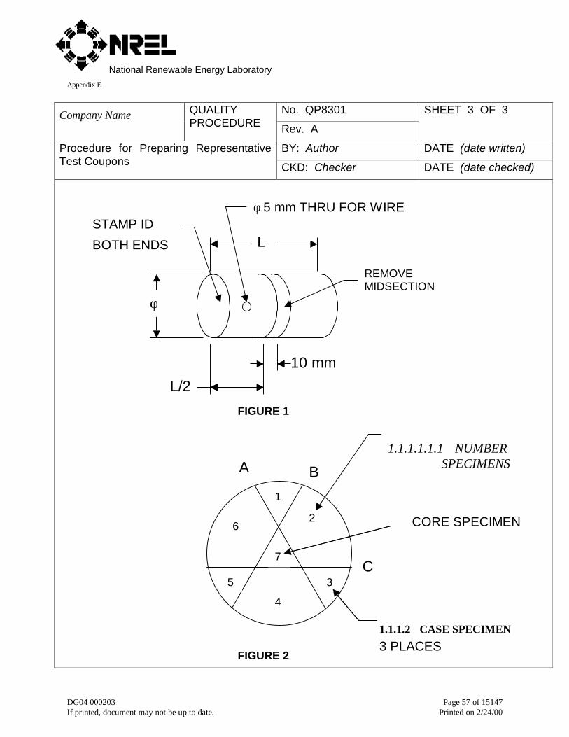
National Renewable Energy LaboratoryAppendix E
DG04 000203 Page 57 of 15147If printed, document may not be up to date. Printed on 2/24/00
No. QP8301Company Name QUALITYPROCEDURE Rev. A
SHEET 3 OF 3
BY: Author DATE (date written)Procedure for Preparing RepresentativeTest Coupons CKD: Checker DATE (date checked)
L
φ
L/210 mm
REMOVEMIDSECTION
FIGURE 1
FIGURE 2
1.1.1.1.2B
C
CORE SPECIMEN
1.1.1.2 CASE SPECIMEN
3 PLACES
A
φ 5 mm THRU FOR WIRESTAMP ID
BOTH ENDS
6
4
2
5
1
3
7
1.1.1.1.1.1 NUMBERSPECIMENS
AS SHOWN

National Renewable Energy LaboratoryAppendix E
DG04 000203 Page 58 of 15147If printed, document may not be up to date. Printed on 2/24/00
No. QP8303Company Name QUALITYPROCEDURE Rev. A
SHEET 1 OF 2
BY: Author DATE (date written)Inspection of Case Depth
CKD: Checker DATE (date checked)
1. Scope
1.1 This procedure covers inspection of case depth on representative test coupons for use in moni-toring heat treatment of carburized gears.
2. Referenced Documents
2.1 QP8301 Procedure for Preparing Representative Test Coupons
2.2 ASTM E384 Standard Test Method for Microhardness of Materials
3. Terminology
3.1 Representative test coupon- A coupon designed to represent the cooling rate of the teeth of aparticular carburized and hardened gear.
3.2 Effective case depth- Distance from the surface of the representative test coupon including oxidescale to where the hardness is 50 HRC by conversion from a microhardness number.
3.3 Effective case depth after grind- Distance obtained by subtracting the material removed duringgrinding of the gear from the effective case depth.
4. Significance and Use
5. Apparatus
5.1 Microhardness testing machine- Either a Vickers or Knoop test machine shall be used.
5.2 Standardized test block- A test block certified to 58 HRC hardness and traceable to NIST shall beused.
6. Test Specimens
6.1 Representative test coupons- Microhardness tests shall be performed on representative test cou-pons conforming to QP8301.
7. Procedure
7.1 Indenter load- The indenter load shall be 500 g.
7.2 Verification of test machine- The accuracy and repeatability of the hardness tester shall be veri-fied before and after any hardness survey is made. At each verification, five tests shall be takenon the hardness test block. The average reading shall be in the limits of 57.5 and 58.5 HRC. Therange of readings shall be within 57 and 59 HRC
7.3 Calibration of test machine- The hardness tester shall be adjusted to maintain accuracy and re-peatability within limits for average and range of readings specified in 7.2 Verification.
National Renewable Energy LaboratoryAppendix E
DG04 000203 Page 59 of 15147If printed, document may not be up to date. Printed on 2/24/00
No. QP8303Company Name QUALITYPROCEDURE Rev. A
SHEET 2 OF 2
BY: Author DATE (date written)Inspection of Case Depth
CKD: Checker DATE (date checked)
7.4 Depth of first indentation- The first indentation shall be 0.1 mm from the surface includingoxide scale.
7.5 Spacing of indentations- Spacing of indentations shall be 0.1 mm.
7.6 Depth of survey- The microhardness survey shall extend to at least twice the effective casedepth.
8. Interpretation of Results
8.1 Hardness gradient- The results of the microhardness survey shall be plotted on a graph ofhardness versus depth from the surface.
8.2 Effective case depth after grind- The effective case depth after grind shall be determinedfrom the hardness gradient by subtracting the material removed during grinding of the gearfrom the effective case depth.
8.3 Case hardness- The case hardness shall be determined from the hardness gradient at adepth corresponding to the material removed during grinding of the gear.
9. Acceptance Criteria
9.1 Effective case depth after grind- The effective case depth after grind shall be within the lim-its specified on the engineering drawing for the gear represented by the representative testcoupon.
9.2 Case hardness- The case hardness shall be 58-62 HRC after conversion from a microhard-ness number.
9.3 Hardness difference- The hardness difference between the surface hardness and themaximum hardness below the surface shall not exceed 2 HRC after conversion from a mi-crohardness number.
10. Report
10.1 The report shall include the following:
10.1.1 Description of the microhardness test machine,
10.1.2 Indenter load,
10.1.3 Graph of microhardness survey,
10.1.4 Effective case depth after grind,
10.1.5 Case hardness, and
10.1.6 Hardness difference between surface and maximum value.
National Renewable Energy LaboratoryAppendix E
DG04 000203 Page 60 of 15147If printed, document may not be up to date. Printed on 2/24/00
No. QP8304Company Name QUALITYPROCEDURE Rev. A
SHEET 1 OF 3
BY: Author DATE (date written)Inspection of Core Hardness
CKD: Checker DATE (date checked)
1. Scope
1.1 This procedure covers inspection of core hardness on representative test coupons for use inmonitoring heat treatment of carburized gears.
2. Referenced Documents
2.1 AGMA/AWEA 921-A97 Recommended Practices for Design and Specification of Gearboxesfor Wind Turbine Generator Systems.
2.2 ASTM E18 Standard Test Methods for Rockwell Hardness and Rockwell Superficial Hardnessof Metallic Materials.
2.3 GEARTECH Specifications:
CK8301 QP8301 Procedure for preparing representative test coupons
3. Terminology
3.1 Representative test coupon- A coupon designed to represent the cooling rate of the teeth ofa particular carburized and hardened gear.
3.2 Core hardness- Rockwell hardness measured on the core specimen.
3.3 Core specimen- The specimen defined in Figure 2 of QP8301.
3.4 Specified core hardness- Hardness limits specified on the engineering drawing for the gearrepresented by the representative test coupon.
4. Significance and Use
4.1 Load capacity- Core hardness must be maintained within specified core hardness to achieveadequate fatigue strength and fracture toughness.
4.2 Process control- Core hardness varies with material hardenability, quench severity, and heattreat process. Core hardness measurements are useful for monitoring process control.
5. Apparatus
5.1 Hardness testing machine- A Rockwell test machine in accordance with ASTM E18 shall beused.
5.2 Standardized test block- A test block in accordance with ASTM E18 and traceable to NISTshall be used. The test block shall be of certified hardness equal to the mid-range of thespecified core hardness ± 4 HRC.
6. Test specimens
6.1 Core specimen- Hardness tests shall be performed on core specimens from representativetest coupons conforming to QP8301.
National Renewable Energy LaboratoryAppendix E
DG04 000203 Page 61 of 15147If printed, document may not be up to date. Printed on 2/24/00
No. QP8304Company Name QUALITYPROCEDURE Rev. A
SHEET 2 OF 3
BY: Author DATE (date written)Inspection of Core Hardness
CKD: Checker DATE (date checked)
7. Procedure
7.1 Specification conformance- The test procedure and test apparatus shall conform to ASTME18.
7.2 Indenter- The indenter shall be a Brale diamond penetrator.
7.3 Indenter load- The major load shall be 150-kgf (1471 N).
7.4 Inspection of indenter- The indenter shall be inspected with a microscope. There shall be nodamage to the indenter tip visible at 30X magnification.
7.5 Verification of test machine- The accuracy and repeatability of the hardness tester shall beverified before and after any hardness test is made. At each verification, five tests shall betaken on the hardness test block. The error and repeatability of the test machine shall bedetermined in accordance with ASTM E18.
7.6 Calibration of test machine- If the error of the test machine exceeds ± 2 HRC it shall be ad-justed. The test machine shall be considered calibrated when its error ≤ ± 2 HRC and its re-peatability ≤ 2 HRC.
7.7 Number of indentations- At least three hardness readings shall be made.
7.8 Spacing of indentations- Spacing shall be in accordance with ASTM E18.
7.9 Load application time- The major load shall be applied for at least 5 seconds after the oper-ating lever stops.
8. Interpretation of results
8.1 Scale reading- Readings shall be estimated to one tenth of a division.
8.2 Core hardness- The core hardness shall be calculated as the mean of the measurements.
8.3 Rounding- The core hardness shall be rounded to the nearest integer. For example, a meanof 35.5 shall be reported as 36 HRC and a mean of 35.4 shall be reported as 35 HRC.
9. Acceptance criteria
9.1 Core hardness- The core hardness shall conform to the specified core hardness.
10. Report
10.1 The report shall include the following:
10.1.1 Serial number of the test machine,
10.1.2 Serial number of the standardized test block,
National Renewable Energy LaboratoryAppendix E
DG04 000203 Page 62 of 15147If printed, document may not be up to date. Printed on 2/24/00
No. QP8304Company Name QUALITYPROCEDURE Rev. A
SHEET 3 OF 3
BY: Author DATE (date written)Inspection of Core Hardness
CKD: Checker DATE (date checked)
10.1.3 Identification number of representative test coupon,
10.1.4 Indenter load,
10.1.5 Load application time, and
10.1.6 Core hardness.

National Renewable Energy LaboratoryAppendix E
DG04 000203 Page 63 of 15147If printed, document may not be up to date. Printed on 2/24/00
No. QP8502Company Name QUALITYPROCEDURE Rev. A
SHEET 1 OF 7
BY: Author DATE (date written)Procedure for Inspection of Gear ToothAccuracy CKD: Checker DATE (date checked)
1. Scope
1.1 This procedure covers inspection of gear tooth accuracy with gear tooth inspection ma-chines.
2. Referenced Documents
2.1 ANSI/AGMA 2000-A88 Gear Classification and Inspection Handbook.
2.2 ANSI/AGMA 2010-A94 Measuring Instrument Calibration – Part I, Involute Measurement.
2.3 ANSI/AGMA 2113-A97 Measuring Instrument Calibration, Gear Tooth Alignment Measure-ment.
2.2 ANSI/AGMA ISO 1328-1 Cylindrical Gears- ISO System of Accuracy- Part 1: Definitions andAllowable Values of Deviations Relevant to Corresponding Flanks of Gear Teeth.
3. Terminology
3.1 Definitions- For definitions of terms see ANSI/AGMA 2000-A88 or ANSI/AGMA ISO 1328-1as appropriate.
3.2 Definitions of terms specific to this Quality Procedure:
3.2.1 Active Flank- The flank that is loaded in service.
3.2.2 Left Hand Helix- A helix that runs in the sense of a left-hand screw thread. Figure 3 showsan internal gear with a left-hand helix.
3.2.3 Left Flank- Looking in the view direction, the left flank bounds the left side of the tooth, whenthe tooth is viewed with the tip above the root.
3.2.4 Right Flank- Looking in the view direction, the right flank bounds the right side of the tooth,when the tooth is viewed with the tip above the root.
3.2.5 Right Hand Helix- A helix that runs in the sense of a right-hand screw thread. Figure 1shows an external gear with a right-hand helix.
3.2.6 Datum Axis- The axis about which the gear rotates during inspection of gear tooth accuracy.The datum axis shall match the functional axis as closely as possible. This is best achievedby using functional mounting surfaces as the datum surfaces.
3.2.7 Functional Axis- The axis about which the gear rotates in service. It is defined by the cen-ters of the functional mounting surfaces.
3.2.8 Reference Face- For symmetrical gears, one face shall be identified with a permanent,unique mark or other unique feature.
National Renewable Energy LaboratoryAppendix E
DG04 000203 Page 64 of 15147If printed, document may not be up to date. Printed on 2/24/00
No. QP8502Company Name QUALITYPROCEDURE Rev. A
SHEET 2 OF 7
BY: Author DATE (date written)Procedure for Inspection of Gear ToothAccuracy CKD: Checker DATE (date checked)
3.2.9 Evaluation length- That part of the usable length to which the tolerances of the specified ac-curacy class shall apply. Unless otherwise specified, the evaluation length for a profile chartshall extend from MAX CHAM to PCD, and the evaluation length for a tooth alignment chartshall extend for the central 90% of the face width.
3.2.10 MIN CHAM- Position on the profile chart corresponding to the maximum tip radius minus theminimum tip chamfer.
3.2.11 MAX CHAM- Position on the profile chart corresponding to the minimum tip radius minus themaximum tip chamfer.
3.2.12 MOD- Position on the profile chart corresponding to the start of tip or root relief.
3.2.13 HPSTC- Position on the profile chart corresponding to the highest-point-of-single-tooth-contact.
3.2.14 LPSTC- Position on the profile chart corresponding to the lowest-point-of-single-tooth-contact.
3.2.15 SAP- Position on the profile chart corresponding to the start-of-active-profile.
3.2.16 PCD- Position on the profile chart corresponding to the profile control diameter.
4. Significance and Use- Unless otherwise specified, all gears shall meet the accuracy re-quirements for AGMA quality No. Q11 in accordance with ANSI/AGMA 2000-A88. The gearquality is an indication of geometric accuracy of the gear. The higher the quality the higherthe load capacity and the lower the noise level.
4.1 Application- This quality procedure applies to ground gears.
5. Apparatus
5.1 Gear teeth shall be inspected on a mechanical or computer numerically controlled (CNC)gear tooth inspection machine. Gear tooth inspections shall not be done on the gear toothgrinding machine.
6. Test Specimens
6.1 Gears- Accuracy measurements shall be performed on gear teeth after all grinding is com-pleted.
7. Procedure
7.1 Temperature- Temperature in the immediate area of the inspection machine shall be20°C ± 2°C.
National Renewable Energy LaboratoryAppendix E
DG04 000203 Page 65 of 15147If printed, document may not be up to date. Printed on 2/24/00
No. QP8502Company Name QUALITYPROCEDURE Rev. A
SHEET 3 OF 7
BY: Author DATE (date written)Procedure for Inspection of Gear ToothAccuracy CKD: Checker DATE (date checked)
7.2 Verification- The accuracy and repeatability of the accuracy inspection machine shall beverified before any group of gears is inspected. At each verification, profile, tooth alignment,and pitch shall be checked on an artifact. Measured accuracy shall be within 2µm of theknown dimension of the artifact.
7.3 Calibration- The inspection machine shall be adjusted to maintain accuracy and repeatabilitywithin limits specified in 7.2 Verification and as specified by ANSI/AGMA 2010-A94 andANSI/AGMA 2113-A97.
7.4 Setup- Gears shall be setup in the gear inspection machine such that runout of datum (func-tional) surfaces is easily measured.
7.4.1 Gears shall be inspected on the shafts they will operate on.
7.4.2 Runout of datum (functional) surfaces shall be recorded.
7.4.3 Teeth shall be identified as shown in Figure 2 or 4 and be numbered permanently.
7.4.4 Reference face shall be identified as shown in Figure 1 or 2 and be numbered permanently.
7.4.5 Number of teeth inspected- Unless otherwise specified, profile and helix alignment shall bemeasured on the active flanks of four teeth equally spaced around the gear. Pitch shall bemeasured on all teeth.
7.4.6 Measurement Position- Unless otherwise specified, measurements shall be made near mid-face for profiles, along the pitchline for helix alignment, and near midface and pitchline forpitch.
7.5 Profile and tooth alignment chart annotations- All charts shall include the following:
7.5.1 Inspectors stamp and date.
7.5.2 Serial number of gear inspected.
7.5.3 Sketch of gear orientation in the inspection machine showing direction of helix, top of gear,view direction, and reference face (for symmetrical gears) as shown in Figure 1 or 3.
7.5.4 Sketch of end view of at least two teeth showing left/right flank designation, active flankdesignation, and tooth numbering convention as shown in Figure 2 or 4. End view shall beconsistent with view direction specified in 7.5.3.
7.5.5 Table showing number of teeth (z), normal module (mn), normal pressure angle (α), helix an-gle (β), face width (b), and hand of helix.
National Renewable Energy LaboratoryAppendix E
DG04 000203 Page 66 of 15147If printed, document may not be up to date. Printed on 2/24/00
No. QP8502Company Name QUALITYPROCEDURE Rev. A
SHEET 4 OF 7
BY: Author DATE (date written)Procedure for Inspection of Gear ToothAccuracy CKD: Checker DATE (date checked)
7.6 Profile chart annotations- All profile charts shall include the following annotations:
7.6.1 Tooth numbers of teeth inspected.
7.6.2 Left /right flank designation, active flank, and tip or root.
7.6.3 Magnification of chart in horizontal and vertical directions.
7.6.4 Base tangent lengths, roll angles or diameters corresponding to the following:
7.6.4.1 MIN CHAM, MAX CHAM,
7.6.4.2 MOD, HPSTC, LPSTC, SAP and PCD.
7.6.4.3 Evaluation length.
7.7 Tooth Alignment Chart Annotations- All tooth alignment charts shall include the followingannotations:
7.7.1 Tooth numbers of teeth inspected.
7.7.2 Left/right flank designation, active flank, and top of gear consistent with Section 7.5.3.
7.7.3 Magnification of chart in horizontal and vertical directions.
7.7.4 Start of helix modifications.
7.7.5 Evaluation length.
8. Interpretation of Results
8.1 Accuracy- Accuracy of profile, tooth alignment, pitch, and runout shall be determined inaccordance with ANSI/AGMA 2000-A88 or ANSI/AGMA ISO 1328-1 as specified on theengineering drawing for the gear.
8.2 Profile and helix modifications- Accuracy of profile and helix modifications shall be deter-mined in accordance with the engineering drawing for the gear.
9. Acceptance Criteria
9.1 Accuracy- The accuracy class shall be determined from the maximum variation of profile,tooth alignment, or pitch for any one tooth, or runout for all teeth. The accuracy shall bewithin the AGMA or ISO accuracy class specified on the engineering drawing for the gear.
9.2 Profile and helix modifications- Location and magnitude of modifications shall be within thetolerances specified on the engineering drawing for the gear.
10. Report
10.1 The report shall include the following:
National Renewable Energy LaboratoryAppendix E
DG04 000203 Page 67 of 15147If printed, document may not be up to date. Printed on 2/24/00
No. QP8502Company Name QUALITYPROCEDURE Rev. A
SHEET 5 OF 7
BY: Author DATE (date written)Procedure for Inspection of Gear ToothAccuracy CKD: Checker DATE (date checked)
10.1.1 Description of the accuracy inspection machine.
10.1.2 Profile charts.
10.1.3 Tooth alignment charts.
10.1.4 Pitch charts.
10.1.5 Accuracy class.
10.1.6 Records of calibrations.

National Renewable Energy LaboratoryAppendix E
DG04 000203 Page 68 of 15147If printed, document may not be up to date. Printed on 2/24/00
No. QP8502Company Name QUALITYPROCEDURE Rev. A
SHEET 6 OF 7
BY: Author DATE (date written)Procedure for Inspection of Gear ToothAccuracy CKD: Checker DATE (date checked)
FIGURE 1
FIGURE 2
REF
TOPA
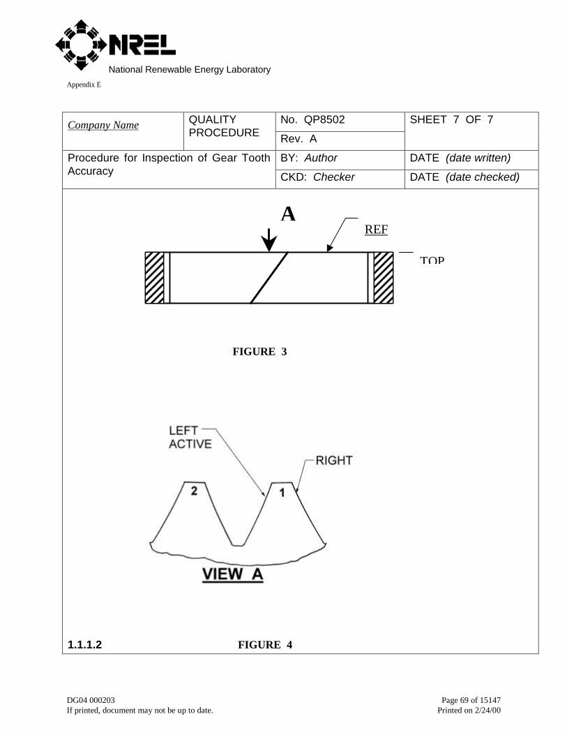
National Renewable Energy LaboratoryAppendix E
DG04 000203 Page 69 of 15147If printed, document may not be up to date. Printed on 2/24/00
No. QP8502Company Name QUALITYPROCEDURE Rev. A
SHEET 7 OF 7
BY: Author DATE (date written)Procedure for Inspection of Gear ToothAccuracy CKD: Checker DATE (date checked)
FIGURE 3
1.1.1.2 FIGURE 4
AREF
TOP
National Renewable Energy LaboratoryAppendix E
DG04 000203 Page 70 of 15147If printed, document may not be up to date. Printed on 2/24/00
No. QP8508Company Name QUALITYPROCEDURE Rev. B
SHEET 1 OF 2
BY: Author DATE (date written)Procedure for Inspection of Gear ToothSurface Hardness CKD: Checker DATE (date checked)
1. Scope
1.1 This procedure covers inspection of gear tooth surface hardness with portable hardness testers.
2. Referenced Documents
2.1 ASTM E110 Standard Test Method for Indentation Hardness of Metallic Materials by PortableHardness Testers.
2.2 ASTM A956 Standard Test Method for Equotip Hardness Testing of Steel Products.
3. Terminology
3.1 Surface hardness-
4. Significance and Use
4.1 Application-
5. Apparatus
5.1 Hardness tester- Either a Microdur or an Equotip hardness tester shall be used.
5.2 Hardness test block- A test block certified to 58 HRC hardness and traceable to NIST shall beused.
6. Test Specimens
6.1 Gears- Hardness tests shall be performed on gear teeth after all grinding is completed.
7. Procedure
7.1 Readout Scale- Readout shall be displayed in Rockwell C (HRC) units.
7.2 Verification- The accuracy and repeatability of the hardness tester shall be verified before andafter any series of hardness measurements are made. At each verification, five tests shall betaken on the hardness test block. The average reading shall be within the limits of 57.5 and58.5 HRC. The range of readings shall be within 57 and 59 HRC.
7.3 Calibration- The hardness tester shall be adjusted to maintain accuracy and repeatability withinlimits for average and range of readings specified in 7.2 Verification.
8. Interpretation of Results
8.1 Rounding- Readings shall be rounded to nearest integer. For example, a reading of 57.5 shallbe reported as 58 HRC and a reading of 57.4 shall be reported as 57 HRC.
National Renewable Energy LaboratoryAppendix E
DG04 000203 Page 71 of 15147If printed, document may not be up to date. Printed on 2/24/00
No. QP8508Company Name QUALITYPROCEDURE Rev. B
SHEET 2 OF 2
BY: Author DATE (date written)Procedure for Inspection of Gear ToothSurface Hardness CKD: Checker DATE (date checked)
9. Acceptance Criteria
9.1 Minimum Hardness- Minimum hardness shall be 58 HRC. If any reading is less than 58 HRC,three additional readings shall be taken within 3 mm of the low reading. The average of thethree additional readings shall be 58 HRC minimum after rounding per 8.1 Rounding. Other-wise, the gear is rejectable.
9.2 Maximum Hardness- Maximum hardness shall be in accordance with drawing specification.
10. Report
10.1 The report shall include the following:
10.1.1 Description of the hardness test machine.
10.1.2 Minimum surface hardness.
10.1.3 Maximum surface hardness.
10.1.4 Records of calibrations

National Renewable Energy LaboratoryAppendix E
DG04 000203 Page 72 of 15147If printed, document may not be up to date. Printed on 2/24/00
Gearbox Quality Checklists
Checklists are an effective way of verifying that critical steps have been completed in along and complicated process. They can serve as evidence that a quality system existsand being used. They can also help assure repeatable results in a multi-step process.Finally they can be a way of communicating technical information succinctly. The fol-lowing checklists are compliments to the quality procedures (QP) presented in section5. For each QP there is a complimentary CK (checklist). Once again they are intendedto be used and customized to suite the manufacturers purposes.

National Renewable Energy LaboratoryAppendix E
DG04 000203 Page 73 of 15147If printed, document may not be up to date. Printed on 2/24/00
5.9 CK1000 Procurement process
No. CK1000Company Name CHECKLIST
Rev. A
SHEET 1 OF 5
BY: Author DATE (date written)Procurement Process
CKD Checker DATE (date checked)
PROCUREMENT SPECIFICATIONQuestion Y N R Comments
Has a procurement specificationbeen written?
Does the procurement specifica-tion include all items listed inCK2000?
Has a person been assigned toensure the procurement specifi-cation is implemented and main-tained?
Are there procedures for distrib-uting the procurement specifica-tion?
Are there procedures for revisingthe procurement specification?
WORKING WITH BIDDERSQuestion Y N R Comments
Do bidders have experience nec-essary to produce gearboxes thatconform to requirements of theprocurement specification?
Do bidders have capabilities nec-essary to produce gearboxes thatconform to requirements of theprocurement specification?
Do bidders understand the pro-curement specification?
Did bidders submit complete pro-posals including:
Completed questionnaire?
List of exceptions to the procure-

National Renewable Energy LaboratoryAppendix E
DG04 000203 Page 74 of 15147If printed, document may not be up to date. Printed on 2/24/00
ment specification?
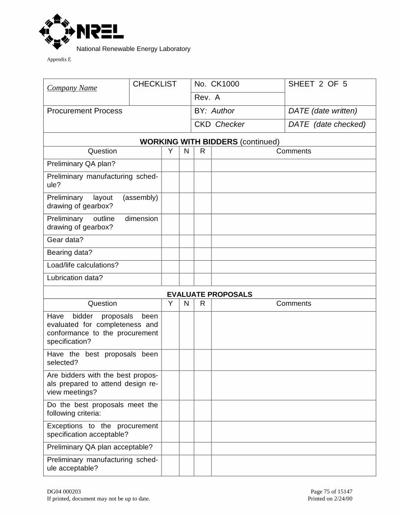
National Renewable Energy LaboratoryAppendix E
DG04 000203 Page 75 of 15147If printed, document may not be up to date. Printed on 2/24/00
No. CK1000Company Name CHECKLIST
Rev. A
SHEET 2 OF 5
BY: Author DATE (date written)Procurement Process
CKD Checker DATE (date checked)
WORKING WITH BIDDERS (continued)Question Y N R Comments
Preliminary QA plan?
Preliminary manufacturing sched-ule?
Preliminary layout (assembly)drawing of gearbox?
Preliminary outline dimensiondrawing of gearbox?
Gear data?
Bearing data?
Load/life calculations?
Lubrication data?
EVALUATE PROPOSALSQuestion Y N R Comments
Have bidder proposals beenevaluated for completeness andconformance to the procurementspecification?
Have the best proposals beenselected?
Are bidders with the best propos-als prepared to attend design re-view meetings?
Do the best proposals meet thefollowing criteria:
Exceptions to the procurementspecification acceptable?
Preliminary QA plan acceptable?
Preliminary manufacturing sched-ule acceptable?

National Renewable Energy LaboratoryAppendix E
DG04 000203 Page 76 of 15147If printed, document may not be up to date. Printed on 2/24/00
No. CK1000Company Name CHECKLIST
Rev. A
SHEET 3 OF 5
BY: Author DATE (date written)Procurement Process
CKD Checker DATE (date checked)
EVALUATE PROPOSALS (continued)Question Y N R Comments
Preliminary design meet require-ments of the procurement specifi-cation?
DESIGN REVIEW MEETINGSQuestion Y N R Comments
Have design review meetingsbeen held with each of the bid-ders with best proposals?
AWARDING CONTRACTQuestion Y N R Comments
Has the bidder with the best pro-posal been selected as the gearmanufacturer?
Has the gear manufacturer beenaudited for conformance toCK5000?
Has the final gearbox design beenaudited by a gear specialist?
Has the contract been awarded?
Does gear manufacturer under-stand that manufacturing shall notcommence until the purchaserapproves the engrg drawings, QAplan, and manufacturing sched-ule?
AUDIT DETAIL DRAWINGSQuestion Y N R Comments
Has the gear manufacturer sub-mitted all data required byCK4000?

National Renewable Energy LaboratoryAppendix E
DG04 000203 Page 77 of 15147If printed, document may not be up to date. Printed on 2/24/00
No. CK1000Company Name CHECKLIST
Rev. A
SHEET 4 OF 5
BY: Author DATE (date written)Procurement Process
CKD Checker DATE (date checked)
AUDIT DETAIL DRAWINGS (continued)Question Y N R Comments
Has all data submitted by the gearmanufacturer been reviewed by agear specialist?
Have the engineering drawingsbeen reviewed by a gear special-ist?
Have the engineering drawingsbeen approved by the purchaser?
AUDIT QA PLANQuestion Y N R Comments
Does the gear manufacturer’s QAplan conform to CK6000?
Has the final QA plan beenaudited by a gear specialist?
Has the final QA plan been ap-proved by the purchaser?
AUDIT MANUFACTURING SCHEDULEQuestion Y N R Comments
Does the gear manufacturer’sMFG schedule conform toCK7000?
Has the final MFG schedule beenaudited by a gear specialist?
Has the final MFG schedule beenapproved by the purchaser?
AUDIT MANUFACTURINGQuestion Y N R Comments
Has gear manufacturing beenaudited for conformance toCK8000?
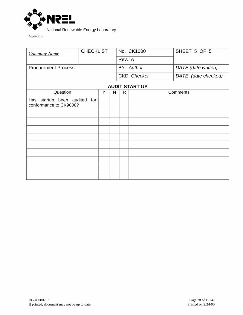
National Renewable Energy LaboratoryAppendix E
DG04 000203 Page 78 of 15147If printed, document may not be up to date. Printed on 2/24/00
No. CK1000Company Name CHECKLIST
Rev. A
SHEET 5 OF 5
BY: Author DATE (date written)Procurement Process
CKD Checker DATE (date checked)
AUDIT START UPQuestion Y N R Comments
Has startup been audited forconformance to CK9000?
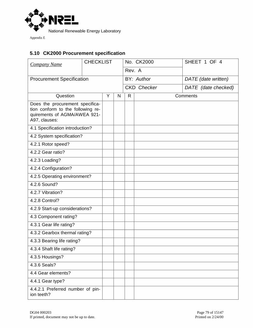
National Renewable Energy LaboratoryAppendix E
DG04 000203 Page 79 of 15147If printed, document may not be up to date. Printed on 2/24/00
5.10 CK2000 Procurement specification
No. CK2000Company Name CHECKLIST
Rev. A
SHEET 1 OF 4
BY: Author DATE (date written)Procurement Specification
CKD Checker DATE (date checked)
Question Y N R Comments
Does the procurement specifica-tion conform to the following re-quirements of AGMA/AWEA 921-A97, clauses:
4.1 Specification introduction?
4.2 System specification?
4.2.1 Rotor speed?
4.2.2 Gear ratio?
4.2.3 Loading?
4.2.4 Configuration?
4.2.5 Operating environment?
4.2.6 Sound?
4.2.7 Vibration?
4.2.8 Control?
4.2.9 Start-up considerations?
4.3 Component rating?
4.3.1 Gear life rating?
4.3.2 Gearbox thermal rating?
4.3.3 Bearing life rating?
4.3.4 Shaft life rating?
4.3.5 Housings?
4.3.6 Seals?
4.4 Gear elements?
4.4.1 Gear type?
4.4.2.1 Preferred number of pin-ion teeth?
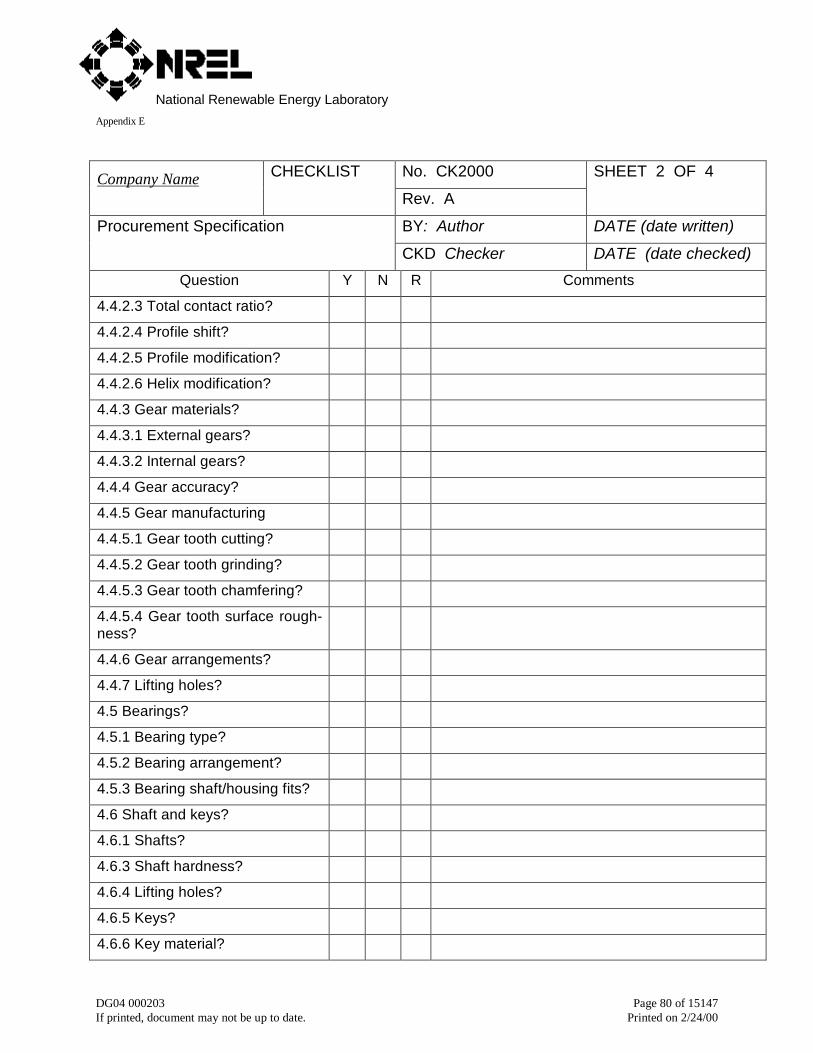
National Renewable Energy LaboratoryAppendix E
DG04 000203 Page 80 of 15147If printed, document may not be up to date. Printed on 2/24/00
No. CK2000Company Name CHECKLIST
Rev. A
SHEET 2 OF 4
BY: Author DATE (date written)Procurement Specification
CKD Checker DATE (date checked)
Question Y N R Comments
4.4.2.3 Total contact ratio?
4.4.2.4 Profile shift?
4.4.2.5 Profile modification?
4.4.2.6 Helix modification?
4.4.3 Gear materials?
4.4.3.1 External gears?
4.4.3.2 Internal gears?
4.4.4 Gear accuracy?
4.4.5 Gear manufacturing
4.4.5.1 Gear tooth cutting?
4.4.5.2 Gear tooth grinding?
4.4.5.3 Gear tooth chamfering?
4.4.5.4 Gear tooth surface rough-ness?
4.4.6 Gear arrangements?
4.4.7 Lifting holes?
4.5 Bearings?
4.5.1 Bearing type?
4.5.2 Bearing arrangement?
4.5.3 Bearing shaft/housing fits?
4.6 Shaft and keys?
4.6.1 Shafts?
4.6.3 Shaft hardness?
4.6.4 Lifting holes?
4.6.5 Keys?
4.6.6 Key material?
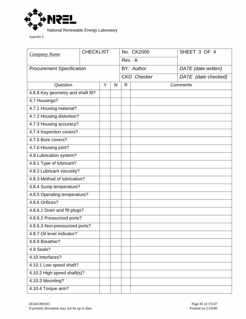
National Renewable Energy LaboratoryAppendix E
DG04 000203 Page 81 of 15147If printed, document may not be up to date. Printed on 2/24/00
No. CK2000Company Name CHECKLIST
Rev. A
SHEET 3 OF 4
BY: Author DATE (date written)Procurement Specification
CKD Checker DATE (date checked)
Question Y N R Comments
4.6.8 Key geometry and shaft fit?
4.7 Housings?
4.7.1 Housing material?
4.7.2 Housing distortion?
4.7.3 Housing accuracy?
4.7.4 Inspection covers?
4.7.5 Bore covers?
4.7.6 Housing joint?
4.8 Lubrication system?
4.8.1 Type of lubricant?
4.8.2 Lubricant viscosity?
4.8.3 Method of lubrication?
4.8.4 Sump temperature?
4.8.5 Operating temperature?
4.8.6 Orifices?
4.8.6.1 Drain and fill plugs?
4.8.6.2 Pressurized ports?
4.8.6.3 Non-pressurized ports?
4.8.7 Oil level indicator?
4.8.9 Breather?
4.9 Seals?
4.10 Interfaces?
4.10.1 Low speed shaft?
4.10.2 High speed shaft(s)?
4.10.3 Mounting?
4.10.4 Torque arm?
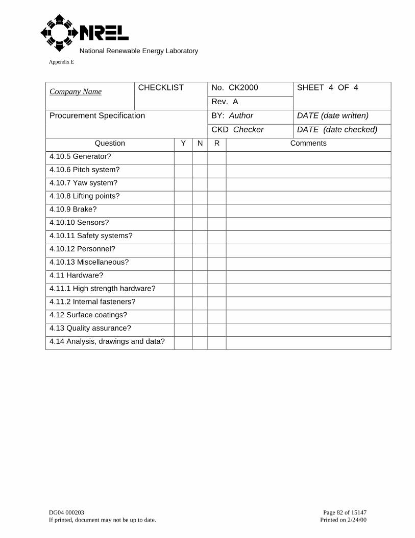
National Renewable Energy LaboratoryAppendix E
DG04 000203 Page 82 of 15147If printed, document may not be up to date. Printed on 2/24/00
No. CK2000Company Name CHECKLIST
Rev. A
SHEET 4 OF 4
BY: Author DATE (date written)Procurement Specification
CKD Checker DATE (date checked)
Question Y N R Comments
4.10.5 Generator?
4.10.6 Pitch system?
4.10.7 Yaw system?
4.10.8 Lifting points?
4.10.9 Brake?
4.10.10 Sensors?
4.10.11 Safety systems?
4.10.12 Personnel?
4.10.13 Miscellaneous?
4.11 Hardware?
4.11.1 High strength hardware?
4.11.2 Internal fasteners?
4.12 Surface coatings?
4.13 Quality assurance?
4.14 Analysis, drawings and data?

National Renewable Energy LaboratoryAppendix E
DG04 000203 Page 83 of 15147If printed, document may not be up to date. Printed on 2/24/00
5.11 CK3000 Bid solicitation and evaluation
No. CK3000Company Name CHECKLIST
Rev. A
SHEET 1 OF 2
BY: Author DATE (date written)Bid Solicitation and Evaluation
CKD Checker DATE (date checked)
BID SOLICITATIONQuestion Y N R Comments
Has a request for a proposal beenwritten?
Does the request for proposal in-clude a procurement specificationper QP2000?
Does the request for proposal in-clude bidding instructions perQP3000?
Has a person been assigned to en-sure the request for proposal is im-plemented and maintained?
Are there procedures for distributingthe request for proposal?
Are guidelines for the procurementprocess (CK1000 and QP1000)being followed?
Are guidelines for bid solicitationand evaluation (QP3000) being fol-lowed?
Is bid solicitation and evaluationcomplete as follows:
Request for proposal sent to bid-ders?
BID EVALUATIONQuestion Y N R Comments
Proposals received from bidders?
Proposals evaluated for complete-ness per CK1000?
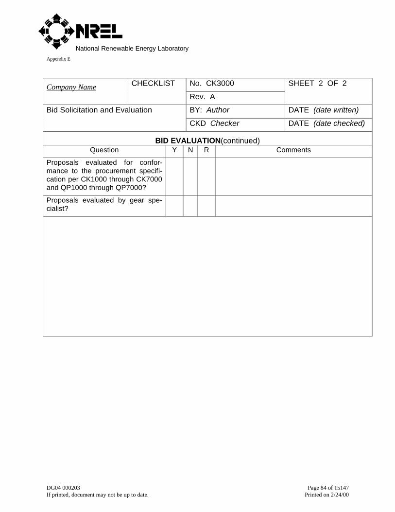
National Renewable Energy LaboratoryAppendix E
DG04 000203 Page 84 of 15147If printed, document may not be up to date. Printed on 2/24/00
No. CK3000Company Name CHECKLIST
Rev. A
SHEET 2 OF 2
BY: Author DATE (date written)Bid Solicitation and Evaluation
CKD Checker DATE (date checked)
BID EVALUATION(continued)Question Y N R Comments
Proposals evaluated for confor-mance to the procurement specifi-cation per CK1000 through CK7000and QP1000 through QP7000?
Proposals evaluated by gear spe-cialist?
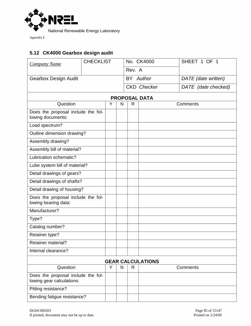
National Renewable Energy LaboratoryAppendix E
DG04 000203 Page 85 of 15147If printed, document may not be up to date. Printed on 2/24/00
5.12 CK4000 Gearbox design audit
No. CK4000Company Name CHECKLIST
Rev. A
SHEET 1 OF 1
BY Author DATE (date written)Gearbox Design Audit
CKD Checker DATE (date checked)
PROPOSAL DATAQuestion Y N R Comments
Does the proposal include the fol-lowing documents:
Load spectrum?
Outline dimension drawing?
Assembly drawing?
Assembly bill of material?
Lubrication schematic?
Lube system bill of material?
Detail drawings of gears?
Detail drawings of shafts?
Detail drawing of housing?
Does the proposal include the fol-lowing bearing data:
Manufacturer?
Type?
Catalog number?
Retainer type?
Retainer material?
Internal clearance?
GEAR CALCULATIONSQuestion Y N R Comments
Does the proposal include the fol-lowing gear calculations:
Pitting resistance?
Bending fatigue resistance?
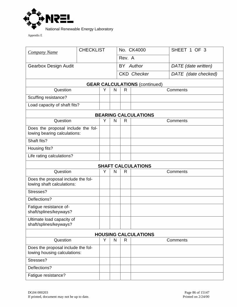
National Renewable Energy LaboratoryAppendix E
DG04 000203 Page 86 of 15147If printed, document may not be up to date. Printed on 2/24/00
No. CK4000Company Name CHECKLIST
Rev. A
SHEET 1 OF 3
BY Author DATE (date written)Gearbox Design Audit
CKD Checker DATE (date checked)
GEAR CALCULATIONS (continued)Question Y N R Comments
Scuffing resistance?
Load capacity of shaft fits?
BEARING CALCULATIONSQuestion Y N R Comments
Does the proposal include the fol-lowing bearing calculations:
Shaft fits?
Housing fits?
Life rating calculations?
SHAFT CALCULATIONSQuestion Y N R Comments
Does the proposal include the fol-lowing shaft calculations:
Stresses?
Deflections?
Fatigue resistance of-shaft/splines/keyways?
Ultimate load capacity ofshaft/splines/keyways?
HOUSING CALCULATIONSQuestion Y N R Comments
Does the proposal include the fol-lowing housing calculations:
Stresses?
Deflections?
Fatigue resistance?

National Renewable Energy LaboratoryAppendix E
DG04 000203 Page 87 of 15147If printed, document may not be up to date. Printed on 2/24/00
No. CK4000Company Name CHECKLIST
Rev. A
SHEET 2 OF 3
BY Author DATE (date written)Gearbox Design Audit
CKD Checker DATE (date checked)
HOUSING CALCULATIONS (continued)Question Y N R Comments
Ultimate load capacity?
Material grade?
Heat treatment?
Surface hardness?
Effective case depth after grind?
Core hardness?
Magnetic particle inspection?
Surface temper etch inspection?
GEAR RATING CALCULATIONSQuestion Y N R Comments
Are reasonable values chosen forthe following parameters:
Load spectrum?
Material grade?
Gear tooth accuracy?
Surface hardness?
Load distribution factor, Cm?
Dynamic factor, Cv?
Gear tooth temperature?
Lubricant dynamic viscosity?
Lubricant pressure-viscosity coeffi-cient?
Gear tooth surface roughness?
Gear tooth coefficient of friction?
Are Miner’s Rule lives adequate?
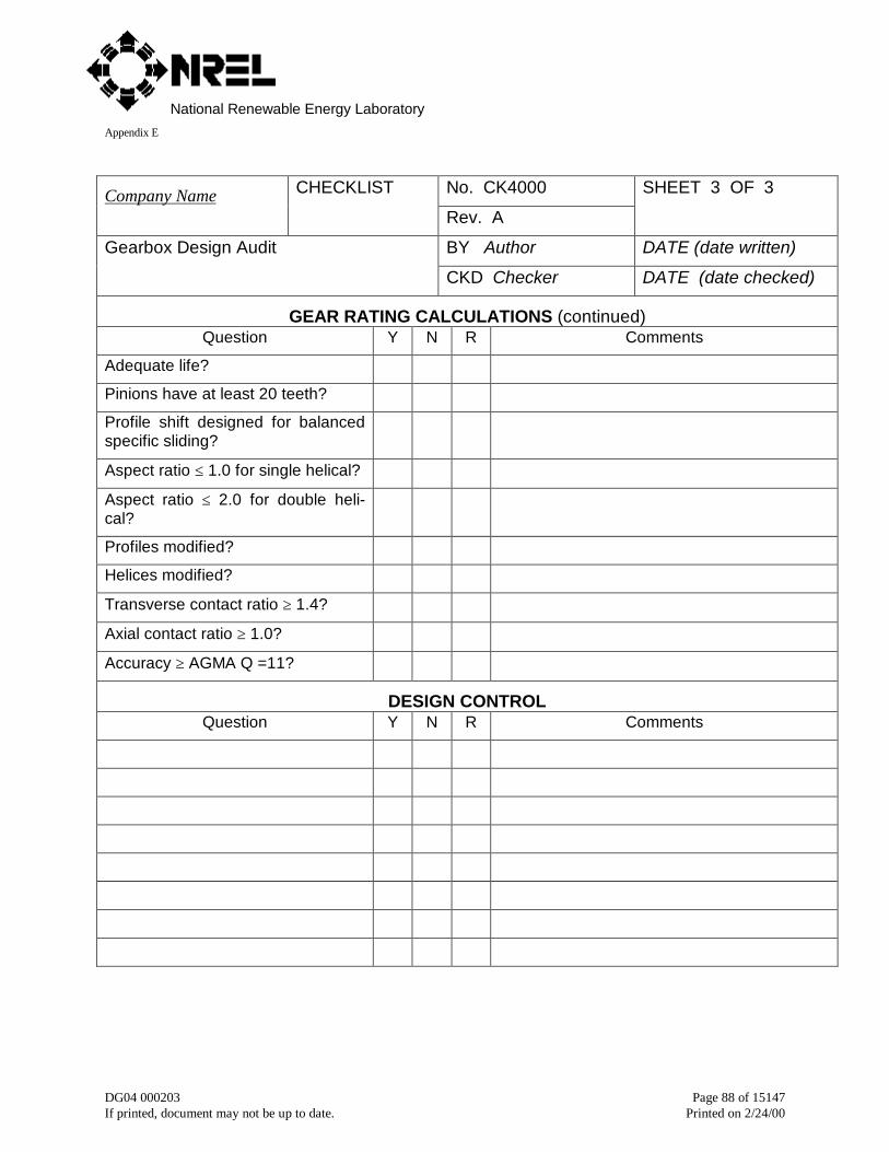
National Renewable Energy LaboratoryAppendix E
DG04 000203 Page 88 of 15147If printed, document may not be up to date. Printed on 2/24/00
No. CK4000Company Name CHECKLIST
Rev. A
SHEET 3 OF 3
BY Author DATE (date written)Gearbox Design Audit
CKD Checker DATE (date checked)
GEAR RATING CALCULATIONS (continued)Question Y N R Comments
Adequate life?
Pinions have at least 20 teeth?
Profile shift designed for balancedspecific sliding?
Aspect ratio ≤ 1.0 for single helical?
Aspect ratio ≤ 2.0 for double heli-cal?
Profiles modified?
Helices modified?
Transverse contact ratio ≥ 1.4?
Axial contact ratio ≥ 1.0?
Accuracy ≥ AGMA Q =11?
DESIGN CONTROLQuestion Y N R Comments
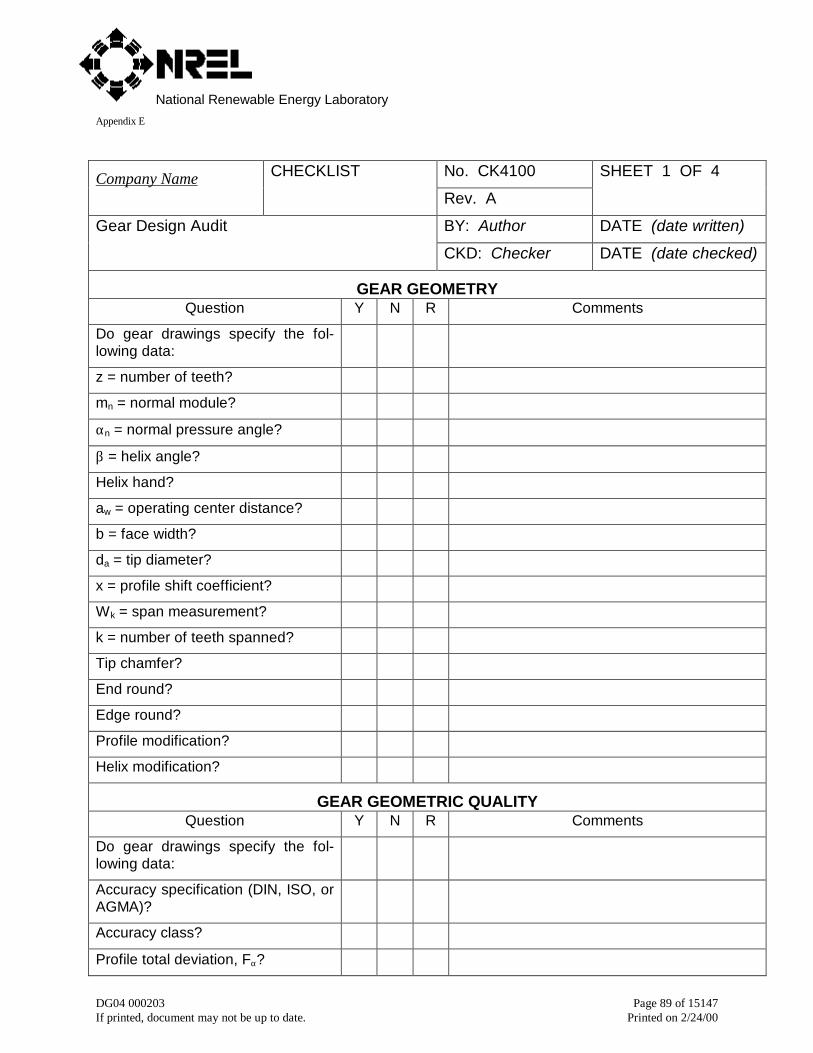
National Renewable Energy LaboratoryAppendix E
DG04 000203 Page 89 of 15147If printed, document may not be up to date. Printed on 2/24/00
No. CK4100Company Name CHECKLIST
Rev. A
SHEET 1 OF 4
BY: Author DATE (date written)Gear Design Audit
CKD: Checker DATE (date checked)
GEAR GEOMETRYQuestion Y N R Comments
Do gear drawings specify the fol-lowing data:
z = number of teeth?
mn = normal module?
αn = normal pressure angle?
β = helix angle?
Helix hand?
aw = operating center distance?
b = face width?
da = tip diameter?
x = profile shift coefficient?
Wk = span measurement?
k = number of teeth spanned?
Tip chamfer?
End round?
Edge round?
Profile modification?
Helix modification?
GEAR GEOMETRIC QUALITYQuestion Y N R Comments
Do gear drawings specify the fol-lowing data:
Accuracy specification (DIN, ISO, orAGMA)?
Accuracy class?
Profile total deviation, Fα?
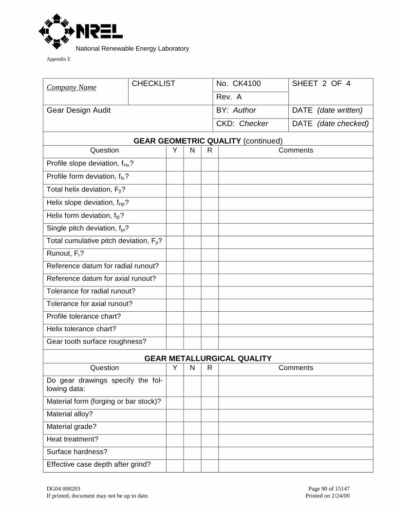
National Renewable Energy LaboratoryAppendix E
DG04 000203 Page 90 of 15147If printed, document may not be up to date. Printed on 2/24/00
No. CK4100Company Name CHECKLIST
Rev. A
SHEET 2 OF 4
BY: Author DATE (date written)Gear Design Audit
CKD: Checker DATE (date checked)
GEAR GEOMETRIC QUALITY (continued)Question Y N R Comments
Profile slope deviation, fHα?
Profile form deviation, ffα?
Total helix deviation, Fβ?
Helix slope deviation, fHβ?
Helix form deviation, ffβ?
Single pitch deviation, fpt?
Total cumulative pitch deviation, Fp?
Runout, Fr?
Reference datum for radial runout?
Reference datum for axial runout?
Tolerance for radial runout?
Tolerance for axial runout?
Profile tolerance chart?
Helix tolerance chart?
Gear tooth surface roughness?
GEAR METALLURGICAL QUALITYQuestion Y N R Comments
Do gear drawings specify the fol-lowing data:
Material form (forging or bar stock)?
Material alloy?
Material grade?
Heat treatment?
Surface hardness?
Effective case depth after grind?
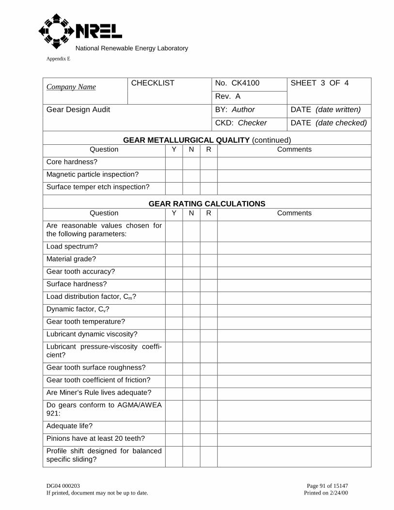
National Renewable Energy LaboratoryAppendix E
DG04 000203 Page 91 of 15147If printed, document may not be up to date. Printed on 2/24/00
No. CK4100Company Name CHECKLIST
Rev. A
SHEET 3 OF 4
BY: Author DATE (date written)Gear Design Audit
CKD: Checker DATE (date checked)
GEAR METALLURGICAL QUALITY (continued)Question Y N R Comments
Core hardness?
Magnetic particle inspection?
Surface temper etch inspection?
GEAR RATING CALCULATIONSQuestion Y N R Comments
Are reasonable values chosen forthe following parameters:
Load spectrum?
Material grade?
Gear tooth accuracy?
Surface hardness?
Load distribution factor, Cm?
Dynamic factor, Cv?
Gear tooth temperature?
Lubricant dynamic viscosity?
Lubricant pressure-viscosity coeffi-cient?
Gear tooth surface roughness?
Gear tooth coefficient of friction?
Are Miner’s Rule lives adequate?
Do gears conform to AGMA/AWEA921:
Adequate life?
Pinions have at least 20 teeth?
Profile shift designed for balancedspecific sliding?
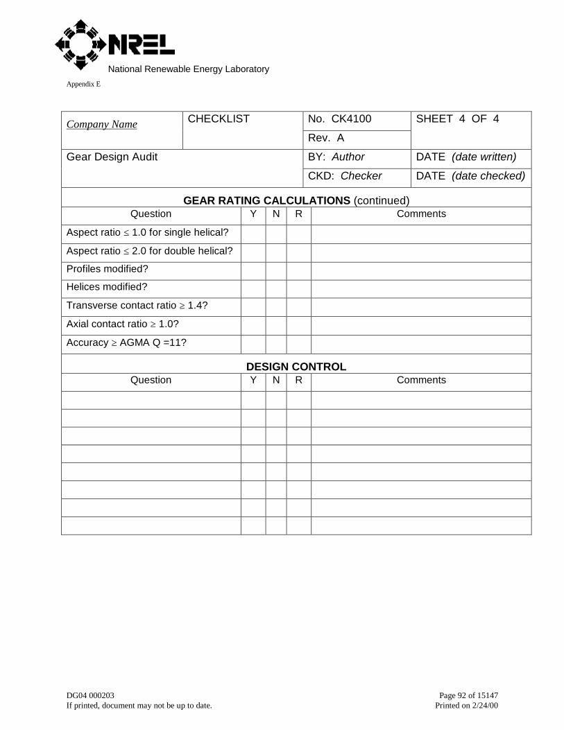
National Renewable Energy LaboratoryAppendix E
DG04 000203 Page 92 of 15147If printed, document may not be up to date. Printed on 2/24/00
No. CK4100Company Name CHECKLIST
Rev. A
SHEET 4 OF 4
BY: Author DATE (date written)Gear Design Audit
CKD: Checker DATE (date checked)
GEAR RATING CALCULATIONS (continued)Question Y N R Comments
Aspect ratio ≤ 1.0 for single helical?
Aspect ratio ≤ 2.0 for double helical?
Profiles modified?
Helices modified?
Transverse contact ratio ≥ 1.4?
Axial contact ratio ≥ 1.0?
Accuracy ≥ AGMA Q =11?
DESIGN CONTROLQuestion Y N R Comments
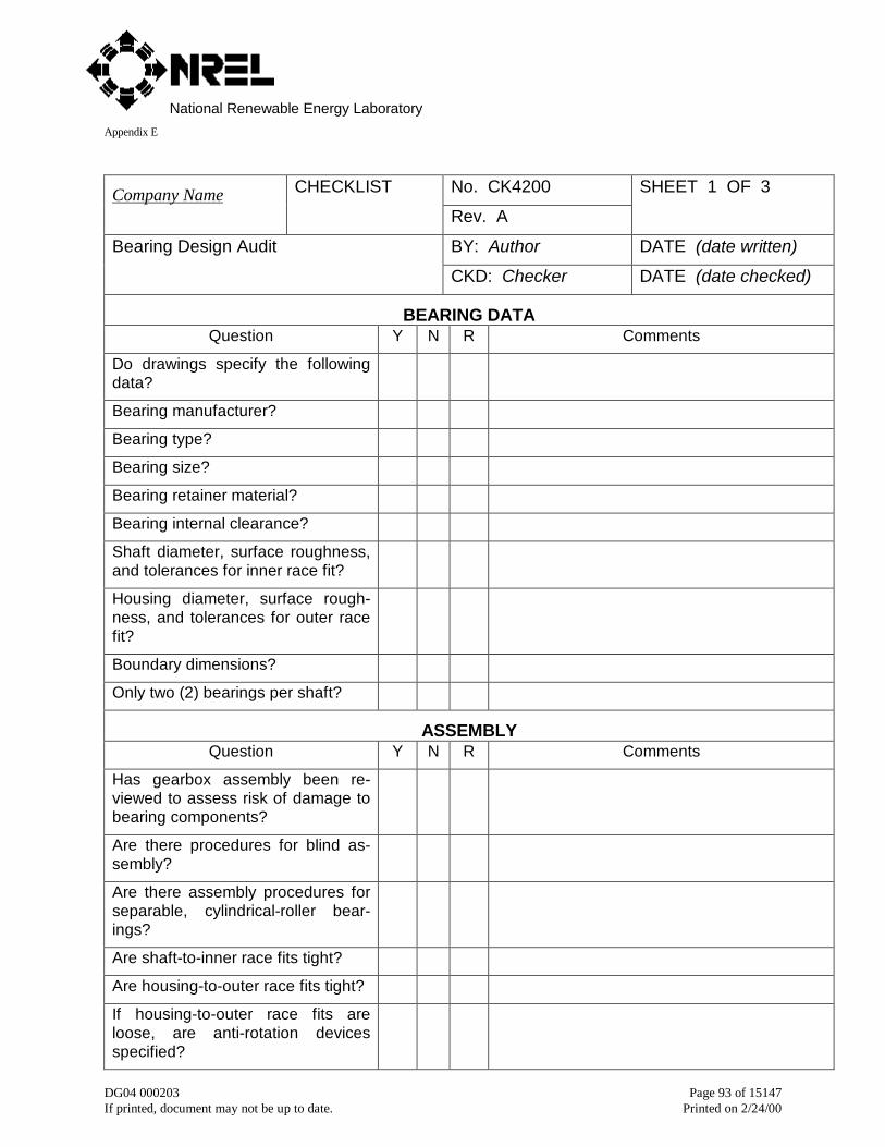
National Renewable Energy LaboratoryAppendix E
DG04 000203 Page 93 of 15147If printed, document may not be up to date. Printed on 2/24/00
No. CK4200Company Name CHECKLIST
Rev. A
SHEET 1 OF 3
BY: Author DATE (date written)Bearing Design Audit
CKD: Checker DATE (date checked)
BEARING DATAQuestion Y N R Comments
Do drawings specify the followingdata?
Bearing manufacturer?
Bearing type?
Bearing size?
Bearing retainer material?
Bearing internal clearance?
Shaft diameter, surface roughness,and tolerances for inner race fit?
Housing diameter, surface rough-ness, and tolerances for outer racefit?
Boundary dimensions?
Only two (2) bearings per shaft?
ASSEMBLYQuestion Y N R Comments
Has gearbox assembly been re-viewed to assess risk of damage tobearing components?
Are there procedures for blind as-sembly?
Are there assembly procedures forseparable, cylindrical-roller bear-ings?
Are shaft-to-inner race fits tight?
Are housing-to-outer race fits tight?
If housing-to-outer race fits areloose, are anti-rotation devicesspecified?
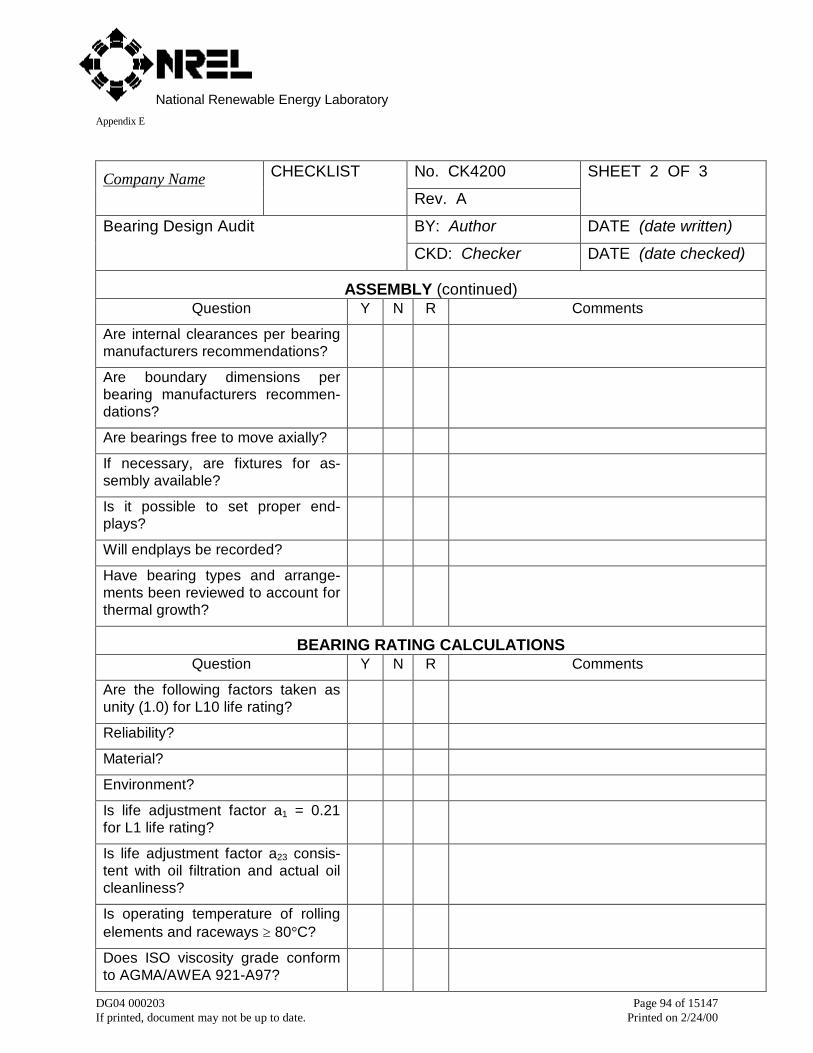
National Renewable Energy LaboratoryAppendix E
DG04 000203 Page 94 of 15147If printed, document may not be up to date. Printed on 2/24/00
No. CK4200Company Name CHECKLIST
Rev. A
SHEET 2 OF 3
BY: Author DATE (date written)Bearing Design Audit
CKD: Checker DATE (date checked)
ASSEMBLY (continued)Question Y N R Comments
Are internal clearances per bearingmanufacturers recommendations?
Are boundary dimensions perbearing manufacturers recommen-dations?
Are bearings free to move axially?
If necessary, are fixtures for as-sembly available?
Is it possible to set proper end-plays?
Will endplays be recorded?
Have bearing types and arrange-ments been reviewed to account forthermal growth?
BEARING RATING CALCULATIONSQuestion Y N R Comments
Are the following factors taken asunity (1.0) for L10 life rating?
Reliability?
Material?
Environment?
Is life adjustment factor a1 = 0.21for L1 life rating?
Is life adjustment factor a23 consis-tent with oil filtration and actual oilcleanliness?
Is operating temperature of rollingelements and raceways ≥ 80°C?
Does ISO viscosity grade conformto AGMA/AWEA 921-A97?
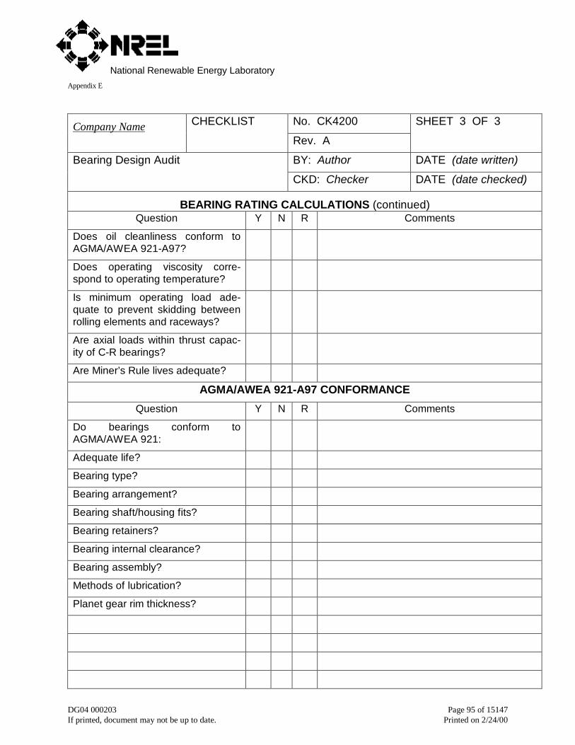
National Renewable Energy LaboratoryAppendix E
DG04 000203 Page 95 of 15147If printed, document may not be up to date. Printed on 2/24/00
No. CK4200Company Name CHECKLIST
Rev. A
SHEET 3 OF 3
BY: Author DATE (date written)Bearing Design Audit
CKD: Checker DATE (date checked)
BEARING RATING CALCULATIONS (continued)Question Y N R Comments
Does oil cleanliness conform toAGMA/AWEA 921-A97?
Does operating viscosity corre-spond to operating temperature?
Is minimum operating load ade-quate to prevent skidding betweenrolling elements and raceways?
Are axial loads within thrust capac-ity of C-R bearings?
Are Miner’s Rule lives adequate?
AGMA/AWEA 921-A97 CONFORMANCE
Question Y N R Comments
Do bearings conform toAGMA/AWEA 921:
Adequate life?
Bearing type?
Bearing arrangement?
Bearing shaft/housing fits?
Bearing retainers?
Bearing internal clearance?
Bearing assembly?
Methods of lubrication?
Planet gear rim thickness?
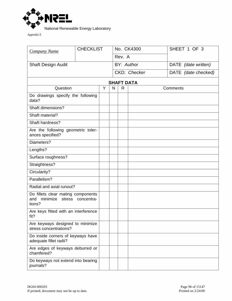
National Renewable Energy LaboratoryAppendix E
DG04 000203 Page 96 of 15147If printed, document may not be up to date. Printed on 2/24/00
No. CK4300Company Name CHECKLIST
Rev. A
SHEET 1 OF 3
BY: Author DATE (date written)Shaft Design Audit
CKD: Checker DATE (date checked)
SHAFT DATAQuestion Y N R Comments
Do drawings specify the followingdata?
Shaft dimensions?
Shaft material?
Shaft hardness?
Are the following geometric toler-ances specified?
Diameters?
Lengths?
Surface roughness?
Straightness?
Circularity?
Parallelism?
Radial and axial runout?
Do fillets clear mating componentsand minimize stress concentra-tions?
Are keys fitted with an interferencefit?
Are keyways designed to minimizestress concentrations?
Do inside corners of keyways haveadequate fillet radii?
Are edges of keyways deburred orchamfered?
Do keyways not extend into bearingjournals?
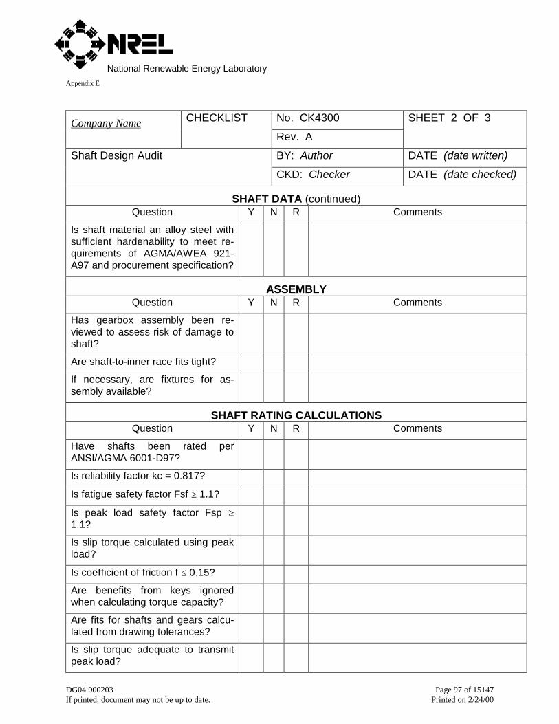
National Renewable Energy LaboratoryAppendix E
DG04 000203 Page 97 of 15147If printed, document may not be up to date. Printed on 2/24/00
No. CK4300Company Name CHECKLIST
Rev. A
SHEET 2 OF 3
BY: Author DATE (date written)Shaft Design Audit
CKD: Checker DATE (date checked)
SHAFT DATA (continued)Question Y N R Comments
Is shaft material an alloy steel withsufficient hardenability to meet re-quirements of AGMA/AWEA 921-A97 and procurement specification?
ASSEMBLYQuestion Y N R Comments
Has gearbox assembly been re-viewed to assess risk of damage toshaft?
Are shaft-to-inner race fits tight?
If necessary, are fixtures for as-sembly available?
SHAFT RATING CALCULATIONSQuestion Y N R Comments
Have shafts been rated perANSI/AGMA 6001-D97?
Is reliability factor kc = 0.817?
Is fatigue safety factor Fsf ≥ 1.1?
Is peak load safety factor Fsp ≥1.1?
Is slip torque calculated using peakload?
Is coefficient of friction f ≤ 0.15?
Are benefits from keys ignoredwhen calculating torque capacity?
Are fits for shafts and gears calcu-lated from drawing tolerances?
Is slip torque adequate to transmitpeak load?
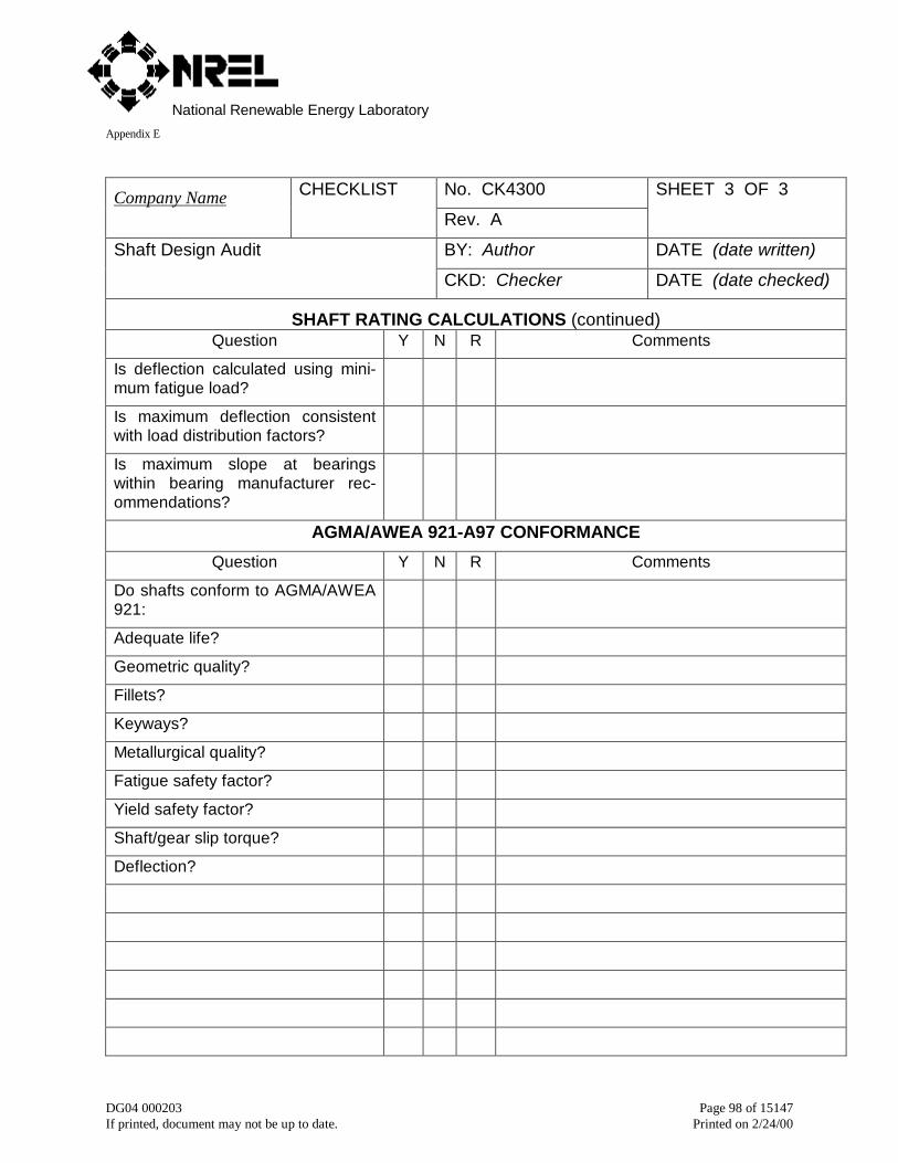
National Renewable Energy LaboratoryAppendix E
DG04 000203 Page 98 of 15147If printed, document may not be up to date. Printed on 2/24/00
No. CK4300Company Name CHECKLIST
Rev. A
SHEET 3 OF 3
BY: Author DATE (date written)Shaft Design Audit
CKD: Checker DATE (date checked)
SHAFT RATING CALCULATIONS (continued)Question Y N R Comments
Is deflection calculated using mini-mum fatigue load?
Is maximum deflection consistentwith load distribution factors?
Is maximum slope at bearingswithin bearing manufacturer rec-ommendations?
AGMA/AWEA 921-A97 CONFORMANCE
Question Y N R Comments
Do shafts conform to AGMA/AWEA921:
Adequate life?
Geometric quality?
Fillets?
Keyways?
Metallurgical quality?
Fatigue safety factor?
Yield safety factor?
Shaft/gear slip torque?
Deflection?
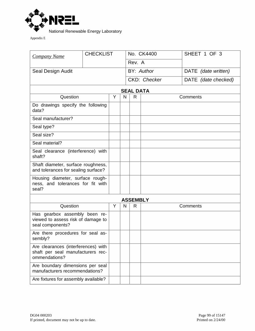
National Renewable Energy LaboratoryAppendix E
DG04 000203 Page 99 of 15147If printed, document may not be up to date. Printed on 2/24/00
No. CK4400Company Name CHECKLIST
Rev. A
SHEET 1 OF 3
BY: Author DATE (date written)Seal Design Audit
CKD: Checker DATE (date checked)
SEAL DATAQuestion Y N R Comments
Do drawings specify the followingdata?
Seal manufacturer?
Seal type?
Seal size?
Seal material?
Seal clearance (interference) withshaft?
Shaft diameter, surface roughness,and tolerances for sealing surface?
Housing diameter, surface rough-ness, and tolerances for fit withseal?
ASSEMBLYQuestion Y N R Comments
Has gearbox assembly been re-viewed to assess risk of damage toseal components?
Are there procedures for seal as-sembly?
Are clearances (interferences) withshaft per seal manufacturers rec-ommendations?
Are boundary dimensions per sealmanufacturers recommendations?
Are fixtures for assembly available?

National Renewable Energy LaboratoryAppendix E
DG04 000203 Page 100 of 15147If printed, document may not be up to date. Printed on 2/24/00
No. CK4400Company Name CHECKLIST
Rev. A
SHEET 2 OF 3
BY: Author DATE (date written)Seal Design Audit
CKD: Checker DATE (date checked)
SEAL DESIGNQuestion Y N R Comments
Are external V-rings used to protectoil seals from contamination?
Are labyrinth seals specified (pre-ferred)?
Do labyrinth seals have properclearances?
Do labyrinth seals have at least twogrooves?
Are labyrinth seals above oil level?
Are lip seals single lip?
Are lip seals Viton?
Are lip seal materials compatiblewith lubricant?
Are lip seals capable of accommo-dating shaft endplay?
Are lip seals capable of accommo-dating shaft heat?
Do lip seals have adequate lubrica-tion?
Are lip seals replaceable in-situ?
Is there adequate access for re-placing lip seals?
AGMA/AWEA 921-A97 CONFORMANCE
Question Y N R Comments
Do seals conform to AGMA/AWEA921:
Adequate life?
Seal type?
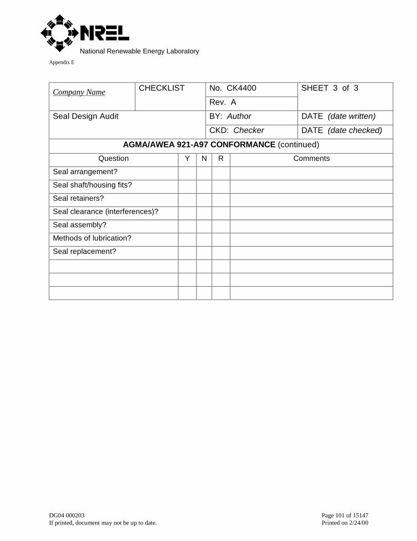
National Renewable Energy LaboratoryAppendix E
DG04 000203 Page 101 of 15147If printed, document may not be up to date. Printed on 2/24/00
No. CK4400Company Name CHECKLIST
Rev. A
SHEET 3 of 3
BY: Author DATE (date written)Seal Design Audit
CKD: Checker DATE (date checked)
AGMA/AWEA 921-A97 CONFORMANCE (continued)
Question Y N R Comments
Seal arrangement?
Seal shaft/housing fits?
Seal retainers?
Seal clearance (interferences)?
Seal assembly?
Methods of lubrication?
Seal replacement?
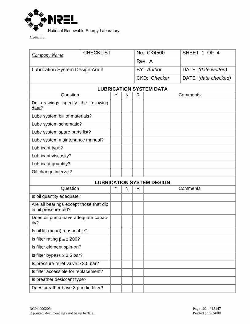
National Renewable Energy LaboratoryAppendix E
DG04 000203 Page 102 of 15147If printed, document may not be up to date. Printed on 2/24/00
No. CK4500Company Name CHECKLIST
Rev. A
SHEET 1 OF 4
BY: Author DATE (date written)Lubrication System Design Audit
CKD: Checker DATE (date checked)
LUBRICATION SYSTEM DATAQuestion Y N R Comments
Do drawings specify the followingdata?
Lube system bill of materials?
Lube system schematic?
Lube system spare parts list?
Lube system maintenance manual?
Lubricant type?
Lubricant viscosity?
Lubricant quantity?
Oil change interval?
LUBRICATION SYSTEM DESIGNQuestion Y N R Comments
Is oil quantity adequate?
Are all bearings except those that dipin oil pressure-fed?
Does oil pump have adequate capac-ity?
Is oil lift (head) reasonable?
Is filter rating β10 ≥ 200?
Is filter element spin-on?
Is filter bypass ≥ 3.5 bar?
Is pressure relief valve ≥ 3.5 bar?
Is filter accessible for replacement?
Is breather desiccant type?
Does breather have 3 µm dirt filter?
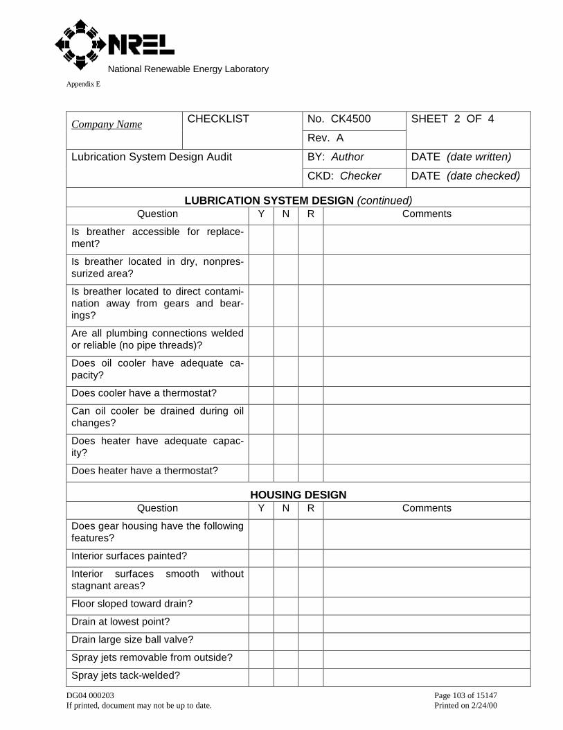
National Renewable Energy LaboratoryAppendix E
DG04 000203 Page 103 of 15147If printed, document may not be up to date. Printed on 2/24/00
No. CK4500Company Name CHECKLIST
Rev. A
SHEET 2 OF 4
BY: Author DATE (date written)Lubrication System Design Audit
CKD: Checker DATE (date checked)
LUBRICATION SYSTEM DESIGN (continued)Question Y N R Comments
Is breather accessible for replace-ment?
Is breather located in dry, nonpres-surized area?
Is breather located to direct contami-nation away from gears and bear-ings?
Are all plumbing connections weldedor reliable (no pipe threads)?
Does oil cooler have adequate ca-pacity?
Does cooler have a thermostat?
Can oil cooler be drained during oilchanges?
Does heater have adequate capac-ity?
Does heater have a thermostat?
HOUSING DESIGNQuestion Y N R Comments
Does gear housing have the followingfeatures?
Interior surfaces painted?
Interior surfaces smooth withoutstagnant areas?
Floor sloped toward drain?
Drain at lowest point?
Drain large size ball valve?
Spray jets removable from outside?
Spray jets tack-welded?
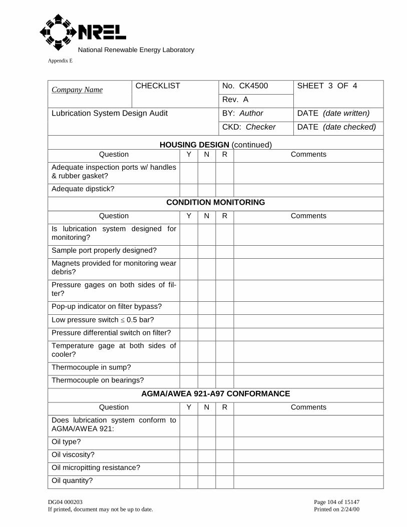
National Renewable Energy LaboratoryAppendix E
DG04 000203 Page 104 of 15147If printed, document may not be up to date. Printed on 2/24/00
No. CK4500Company Name CHECKLIST
Rev. A
SHEET 3 OF 4
BY: Author DATE (date written)Lubrication System Design Audit
CKD: Checker DATE (date checked)
HOUSING DESIGN (continued)Question Y N R Comments
Adequate inspection ports w/ handles& rubber gasket?
Adequate dipstick?
CONDITION MONITORING
Question Y N R Comments
Is lubrication system designed formonitoring?
Sample port properly designed?
Magnets provided for monitoring weardebris?
Pressure gages on both sides of fil-ter?
Pop-up indicator on filter bypass?
Low pressure switch ≤ 0.5 bar?
Pressure differential switch on filter?
Temperature gage at both sides ofcooler?
Thermocouple in sump?
Thermocouple on bearings?
AGMA/AWEA 921-A97 CONFORMANCE
Question Y N R Comments
Does lubrication system conform toAGMA/AWEA 921:
Oil type?
Oil viscosity?
Oil micropitting resistance?
Oil quantity?
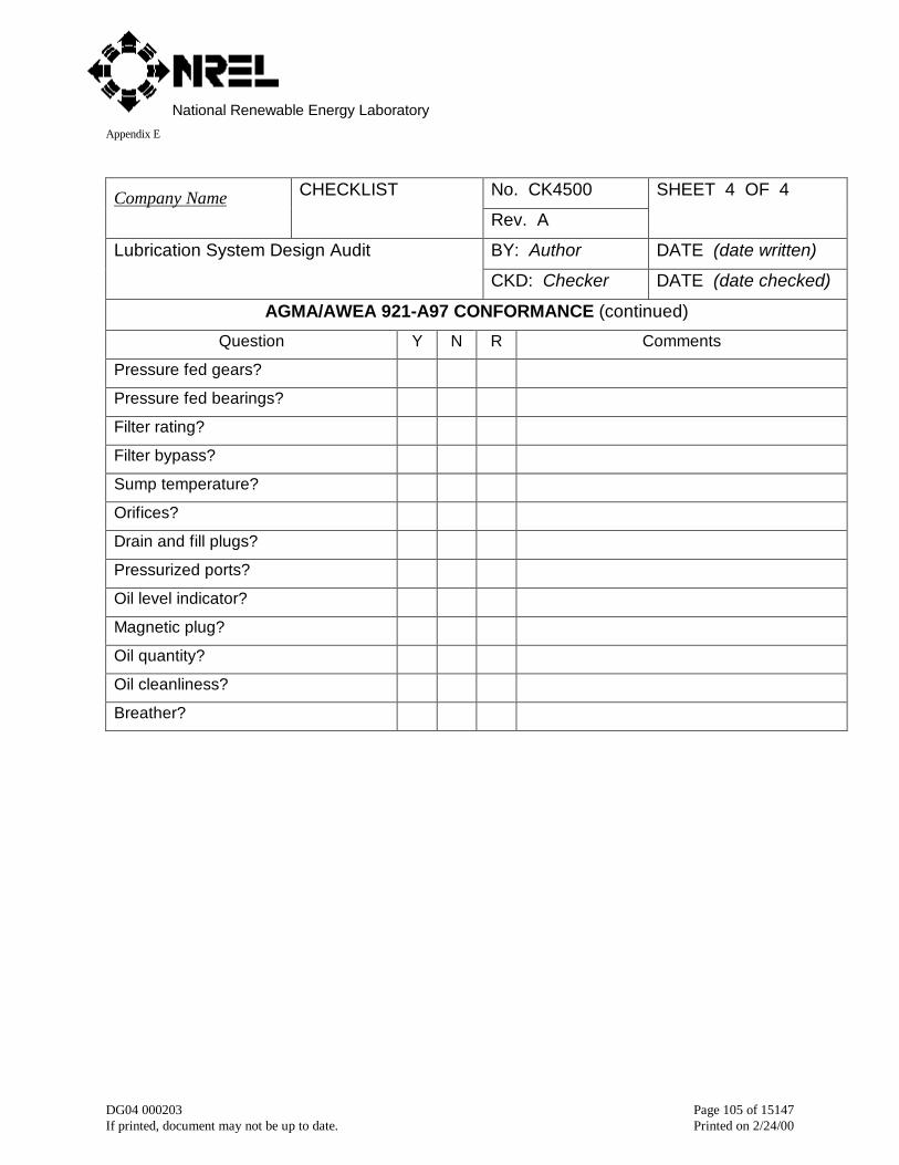
National Renewable Energy LaboratoryAppendix E
DG04 000203 Page 105 of 15147If printed, document may not be up to date. Printed on 2/24/00
No. CK4500Company Name CHECKLIST
Rev. A
SHEET 4 OF 4
BY: Author DATE (date written)Lubrication System Design Audit
CKD: Checker DATE (date checked)
AGMA/AWEA 921-A97 CONFORMANCE (continued)
Question Y N R Comments
Pressure fed gears?
Pressure fed bearings?
Filter rating?
Filter bypass?
Sump temperature?
Orifices?
Drain and fill plugs?
Pressurized ports?
Oil level indicator?
Magnetic plug?
Oil quantity?
Oil cleanliness?
Breather?
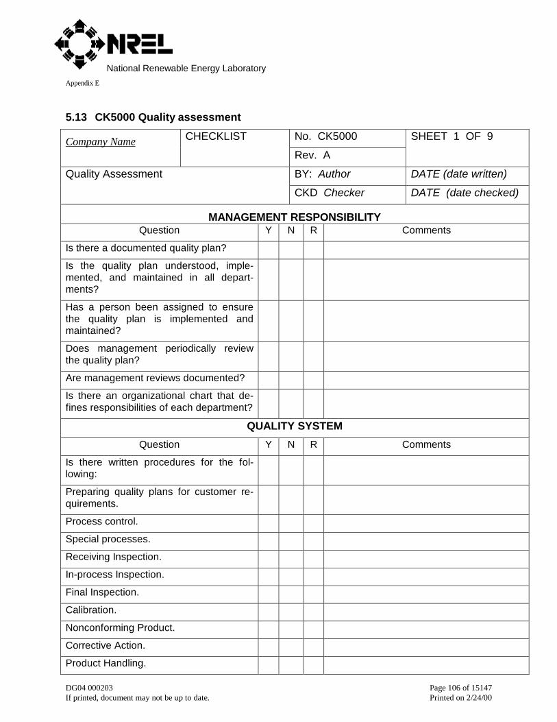
National Renewable Energy LaboratoryAppendix E
DG04 000203 Page 106 of 15147If printed, document may not be up to date. Printed on 2/24/00
5.13 CK5000 Quality assessment
No. CK5000Company Name CHECKLIST
Rev. A
SHEET 1 OF 9
BY: Author DATE (date written)Quality Assessment
CKD Checker DATE (date checked)
MANAGEMENT RESPONSIBILITYQuestion Y N R Comments
Is there a documented quality plan?
Is the quality plan understood, imple-mented, and maintained in all depart-ments?
Has a person been assigned to ensurethe quality plan is implemented andmaintained?
Does management periodically reviewthe quality plan?
Are management reviews documented?
Is there an organizational chart that de-fines responsibilities of each department?
QUALITY SYSTEM
Question Y N R Comments
Is there written procedures for the fol-lowing:
Preparing quality plans for customer re-quirements.
Process control.
Special processes.
Receiving Inspection.
In-process Inspection.
Final Inspection.
Calibration.
Nonconforming Product.
Corrective Action.
Product Handling.
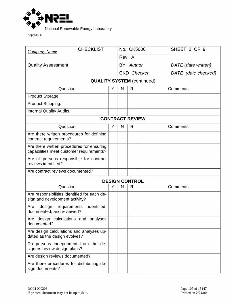
National Renewable Energy LaboratoryAppendix E
DG04 000203 Page 107 of 15147If printed, document may not be up to date. Printed on 2/24/00
No. CK5000Company Name CHECKLIST
Rev. A
SHEET 2 OF 9
BY: Author DATE (date written)Quality Assessment
CKD Checker DATE (date checked)
QUALITY SYSTEM (continued)
Question Y N R Comments
Product Storage.
Product Shipping.
Internal Quality Audits.
CONTRACT REVIEW
Question Y N R Comments
Are there written procedures for definingcontract requirements?
Are there written procedures for ensuringcapabilities meet customer requirements?
Are all persons responsible for contractreviews identified?
Are contract reviews documented?
DESIGN CONTROLQuestion Y N R Comments
Are responsibilities identified for each de-sign and development activity?
Are design requirements identified,documented, and reviewed?
Are design calculations and analysesdocumented?
Are design calculations and analyses up-dated as the design evolves?
Do persons independent from the de-signers review design plans?
Are design reviews documented?
Are there procedures for distributing de-sign documents?
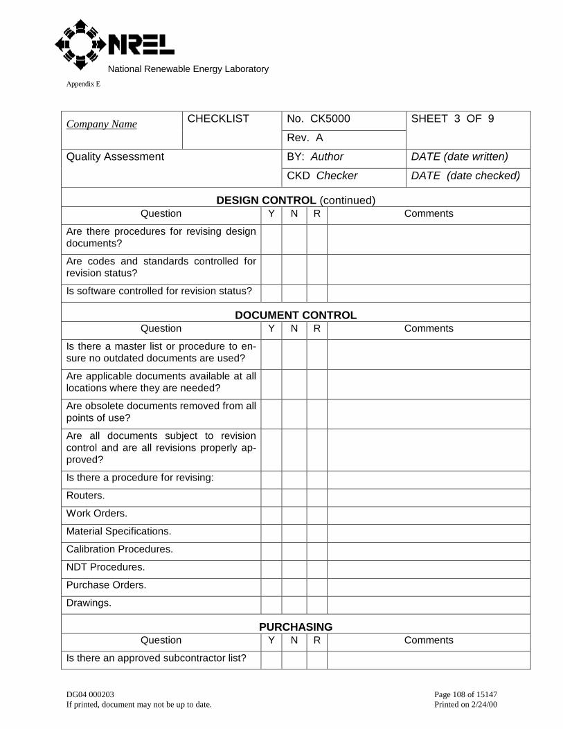
National Renewable Energy LaboratoryAppendix E
DG04 000203 Page 108 of 15147If printed, document may not be up to date. Printed on 2/24/00
No. CK5000Company Name CHECKLIST
Rev. A
SHEET 3 OF 9
BY: Author DATE (date written)Quality Assessment
CKD Checker DATE (date checked)
DESIGN CONTROL (continued)Question Y N R Comments
Are there procedures for revising designdocuments?
Are codes and standards controlled forrevision status?
Is software controlled for revision status?
DOCUMENT CONTROLQuestion Y N R Comments
Is there a master list or procedure to en-sure no outdated documents are used?
Are applicable documents available at alllocations where they are needed?
Are obsolete documents removed from allpoints of use?
Are all documents subject to revisioncontrol and are all revisions properly ap-proved?
Is there a procedure for revising:
Routers.
Work Orders.
Material Specifications.
Calibration Procedures.
NDT Procedures.
Purchase Orders.
Drawings.
PURCHASINGQuestion Y N R Comments
Is there an approved subcontractor list?
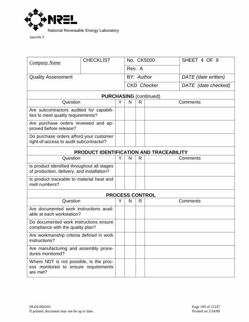
National Renewable Energy LaboratoryAppendix E
DG04 000203 Page 109 of 15147If printed, document may not be up to date. Printed on 2/24/00
No. CK5000Company Name CHECKLIST
Rev. A
SHEET 4 OF 9
BY: Author DATE (date written)Quality Assessment
CKD Checker DATE (date checked)
PURCHASING (continued)Question Y N R Comments
Are subcontractors audited for capabili-ties to meet quality requirements?
Are purchase orders reviewed and ap-proved before release?
Do purchase orders afford your customerright-of-access to audit subcontractor?
PRODUCT IDENTIFICATION AND TRACEABILITYQuestion Y N R Comments
Is product identified throughout all stagesof production, delivery, and installation?
Is product traceable to material heat andmelt numbers?
PROCESS CONTROLQuestion Y N R Comments
Are documented work instructions avail-able at each workstation?
Do documented work instructions ensurecompliance with the quality plan?
Are workmanship criteria defined in workinstructions?
Are manufacturing and assembly proce-dures monitored?
Where NDT is not possible, is the proc-ess monitored to ensure requirementsare met?
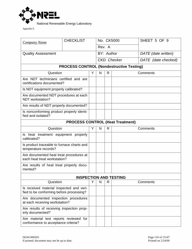
National Renewable Energy LaboratoryAppendix E
DG04 000203 Page 110 of 15147If printed, document may not be up to date. Printed on 2/24/00
No. CK5000Company Name CHECKLIST
Rev. A
SHEET 5 OF 9
BY: Author DATE (date written)Quality Assessment
CKD Checker DATE (date checked)
PROCESS CONTROL (Nondestructive Testing)
Question Y N R Comments
Are NDT technicians certified and arecertifications documented?
Is NDT equipment properly calibrated?
Are documented NDT procedures at eachNDT workstation?
Are results of NDT properly documented?
Is nonconforming product properly identi-fied and isolated?
PROCESS CONTROL (Heat Treatment)
Question Y N R Comments
Is heat treatment equipment properlycalibrated?
Is product traceable to furnace charts andtemperature records?
Are documented heat treat procedures ateach heat treat workstation?
Are results of heat treat properly docu-mented?
INSPECTION AND TESTINGQuestion Y N R Comments
Is received material inspected and veri-fied to be conforming before processing?
Are documented inspection proceduresat each receiving workstation?
Are results of receiving inspection prop-erly documented?
Are material test reports reviewed forconformance to acceptance criteria?
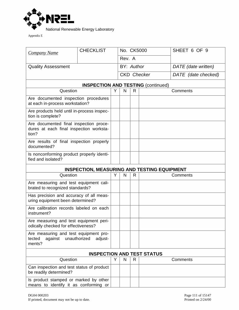
National Renewable Energy LaboratoryAppendix E
DG04 000203 Page 111 of 15147If printed, document may not be up to date. Printed on 2/24/00
No. CK5000Company Name CHECKLIST
Rev. A
SHEET 6 OF 9
BY: Author DATE (date written)Quality Assessment
CKD Checker DATE (date checked)
INSPECTION AND TESTING (continued)Question Y N R Comments
Are documented inspection proceduresat each in-process workstation?
Are products held until in-process inspec-tion is complete?
Are documented final inspection proce-dures at each final inspection worksta-tion?
Are results of final inspection properlydocumented?
Is nonconforming product properly identi-fied and isolated?
INSPECTION, MEASURING AND TESTING EQUIPMENTQuestion Y N R Comments
Are measuring and test equipment cali-brated to recognized standards?
Has precision and accuracy of all meas-uring equipment been determined?
Are calibration records labeled on eachinstrument?
Are measuring and test equipment peri-odically checked for effectiveness?
Are measuring and test equipment pro-tected against unauthorized adjust-ments?
INSPECTION AND TEST STATUSQuestion Y N R Comments
Can inspection and test status of productbe readily determined?
Is product stamped or marked by othermeans to identify it as conforming or

National Renewable Energy LaboratoryAppendix E
DG04 000203 Page 112 of 15147If printed, document may not be up to date. Printed on 2/24/00
nonconforming?
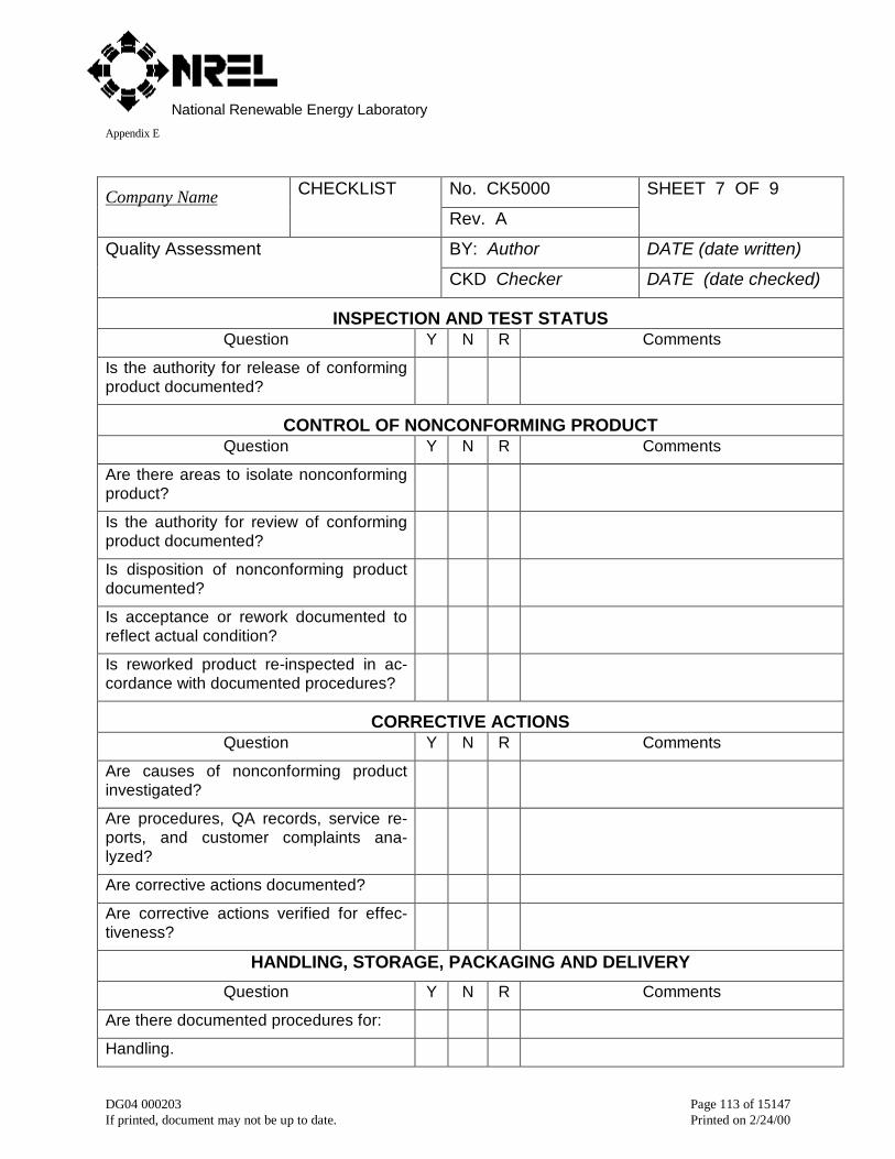
National Renewable Energy LaboratoryAppendix E
DG04 000203 Page 113 of 15147If printed, document may not be up to date. Printed on 2/24/00
No. CK5000Company Name CHECKLIST
Rev. A
SHEET 7 OF 9
BY: Author DATE (date written)Quality Assessment
CKD Checker DATE (date checked)
INSPECTION AND TEST STATUSQuestion Y N R Comments
Is the authority for release of conformingproduct documented?
CONTROL OF NONCONFORMING PRODUCTQuestion Y N R Comments
Are there areas to isolate nonconformingproduct?
Is the authority for review of conformingproduct documented?
Is disposition of nonconforming productdocumented?
Is acceptance or rework documented toreflect actual condition?
Is reworked product re-inspected in ac-cordance with documented procedures?
CORRECTIVE ACTIONSQuestion Y N R Comments
Are causes of nonconforming productinvestigated?
Are procedures, QA records, service re-ports, and customer complaints ana-lyzed?
Are corrective actions documented?
Are corrective actions verified for effec-tiveness?
HANDLING, STORAGE, PACKAGING AND DELIVERY
Question Y N R Comments
Are there documented procedures for:
Handling.
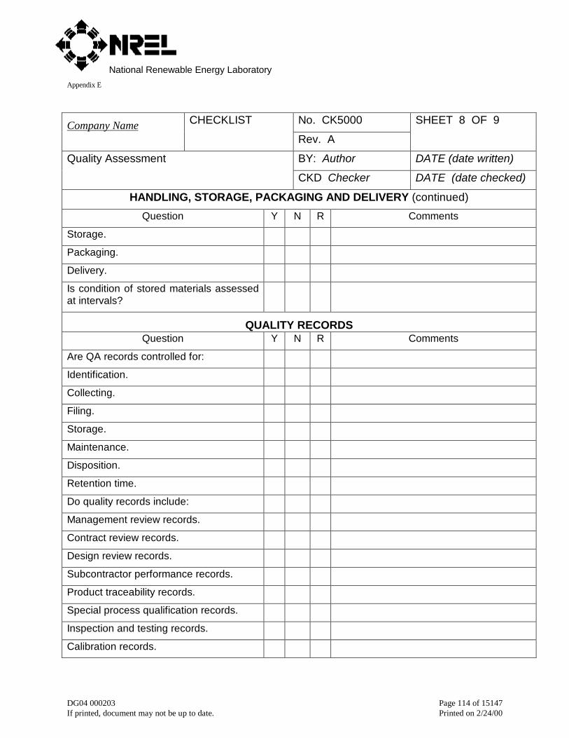
National Renewable Energy LaboratoryAppendix E
DG04 000203 Page 114 of 15147If printed, document may not be up to date. Printed on 2/24/00
No. CK5000Company Name CHECKLIST
Rev. A
SHEET 8 OF 9
BY: Author DATE (date written)Quality Assessment
CKD Checker DATE (date checked)
HANDLING, STORAGE, PACKAGING AND DELIVERY (continued)
Question Y N R Comments
Storage.
Packaging.
Delivery.
Is condition of stored materials assessedat intervals?
QUALITY RECORDSQuestion Y N R Comments
Are QA records controlled for:
Identification.
Collecting.
Filing.
Storage.
Maintenance.
Disposition.
Retention time.
Do quality records include:
Management review records.
Contract review records.
Design review records.
Subcontractor performance records.
Product traceability records.
Special process qualification records.
Inspection and testing records.
Calibration records.
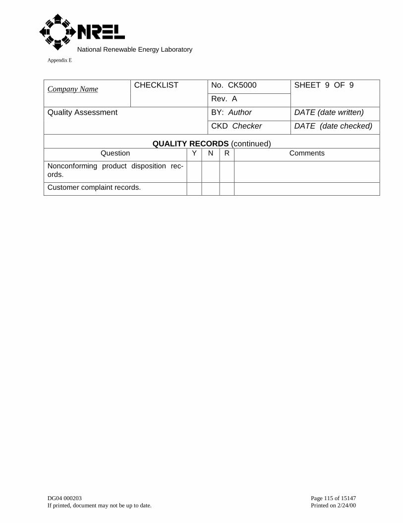
National Renewable Energy LaboratoryAppendix E
DG04 000203 Page 115 of 15147If printed, document may not be up to date. Printed on 2/24/00
No. CK5000Company Name CHECKLIST
Rev. A
SHEET 9 OF 9
BY: Author DATE (date written)Quality Assessment
CKD Checker DATE (date checked)
QUALITY RECORDS (continued)Question Y N R Comments
Nonconforming product disposition rec-ords.
Customer complaint records.

National Renewable Energy LaboratoryAppendix E
DG04 000203 Page 116 of 15147If printed, document may not be up to date. Printed on 2/24/00
5.14 CK6000 Quality assurance plan

National Renewable Energy LaboratoryAppendix E
DG04 000203 Page 117 of 15147If printed, document may not be up to date. Printed on 2/24/00
5.15 CK7000 Manufacturing schedule

National Renewable Energy LaboratoryAppendix E
DG04 000203 Page 118 of 15147If printed, document may not be up to date. Printed on 2/24/00
5.16 CK8000 Manufacturing audit
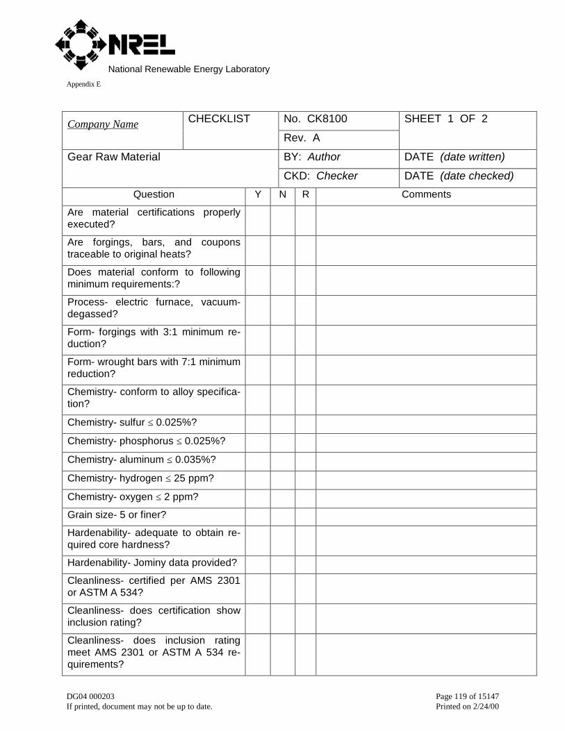
National Renewable Energy LaboratoryAppendix E
DG04 000203 Page 119 of 15147If printed, document may not be up to date. Printed on 2/24/00
No. CK8100Company Name CHECKLIST
Rev. A
SHEET 1 OF 2
BY: Author DATE (date written)Gear Raw Material
CKD: Checker DATE (date checked)
Question Y N R Comments
Are material certifications properlyexecuted?
Are forgings, bars, and couponstraceable to original heats?
Does material conform to followingminimum requirements:?
Process- electric furnace, vacuum-degassed?
Form- forgings with 3:1 minimum re-duction?
Form- wrought bars with 7:1 minimumreduction?
Chemistry- conform to alloy specifica-tion?
Chemistry- sulfur ≤ 0.025%?
Chemistry- phosphorus ≤ 0.025%?
Chemistry- aluminum ≤ 0.035%?
Chemistry- hydrogen ≤ 25 ppm?
Chemistry- oxygen ≤ 2 ppm?
Grain size- 5 or finer?
Hardenability- adequate to obtain re-quired core hardness?
Hardenability- Jominy data provided?
Cleanliness- certified per AMS 2301or ASTM A 534?
Cleanliness- does certification showinclusion rating?
Cleanliness- does inclusion ratingmeet AMS 2301 or ASTM A 534 re-quirements?
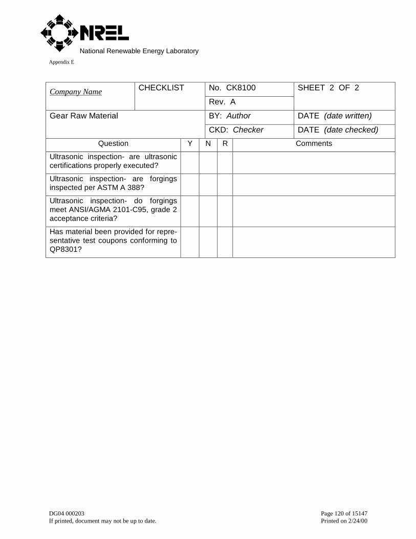
National Renewable Energy LaboratoryAppendix E
DG04 000203 Page 120 of 15147If printed, document may not be up to date. Printed on 2/24/00
No. CK8100Company Name CHECKLIST
Rev. A
SHEET 2 OF 2
BY: Author DATE (date written)Gear Raw Material
CKD: Checker DATE (date checked)
Question Y N R Comments
Ultrasonic inspection- are ultrasoniccertifications properly executed?
Ultrasonic inspection- are forgingsinspected per ASTM A 388?
Ultrasonic inspection- do forgingsmeet ANSI/AGMA 2101-C95, grade 2acceptance criteria?
Has material been provided for repre-sentative test coupons conforming toQP8301?

National Renewable Energy LaboratoryAppendix E
DG04 000203 Page 121 of 15147If printed, document may not be up to date. Printed on 2/24/00
No. CK8300Company Name CHECKLIST
Rev. A
SHEET 1 OF 2
BY: Author DATE (date written)Heat Treatment of Carburized Gears
CKD: Checker DATE (date checked)
Question Y N R Comments
Does heat treater have an in-house met-allurgical laboratory?
Does heat treater have a staff metallur-gist?
Does heat treater have a technician toprepare and analyze heat treat coupons?
Does the laboratory conduct tests to en-sure that the gears conform to specifica-tions?
Does the laboratory prepare reports thatdocument the metallurgical test results?
Are thermocouples properly maintainedand checked against a calibration stan-dard that is traceable to the National Bu-reau of Standards?
Do thermocouples accurately measure thetemperature of the gears?
Is the carbon potential accurately main-tained and monitored?
Is the case carbon content tested withcoupons?
Are gears loaded in the furnace in a waythat prevents sagging at the carburizingtemperature?
Are gears spaced so that teeth do nottouch each other, baskets, or fixtures?
Are fans used to vigorously circulate gas?
Is there a uniform flow of gas in andaround gears?
Are quench tanks large enough for thegears?

National Renewable Energy LaboratoryAppendix E
DG04 000203 Page 122 of 15147If printed, document may not be up to date. Printed on 2/24/00
No. CK8300Company Name CHECKLIST
Rev. A
SHEET 2 OF 2
BY: Author DATE (date written)Heat Treatment of Carburized Gears
CKD: Checker DATE (date checked)
Question Y N R Comments
Is quenchant circulated with pumps?
Is a minimum flow of 1 (one) gpm/lb ofsteel provided?
Has quench vigor been determined bymeasuring H value?
Is there a uniform flow of quenchant inand around gears?
Do representative test coupons conformto the following:
QP8301 Procedure for preparing repre-sentative test coupons
QP8302 Inspection of surface hardness
QP8303 Inspection of case depth
QP8304 Inspection of core hardness
QP8305 Inspection of case microstructure
QP8306 Inspection for carbides
QP8307 Inspection for decarburization
QP8308 Inspection for carbon content
QP8309 Inspection for microcracks
QP8310 Inspection for secondary trans-formation products
QP8311 Inspection for intergranular oxi-dation
QP8312 Inspection for retained austenite
QP8313 Inspection of core microstructure
QP8314 Procedure for post carburizingcold treatment
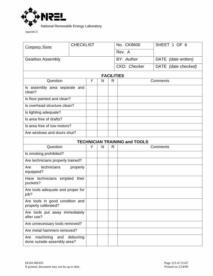
National Renewable Energy LaboratoryAppendix E
DG04 000203 Page 123 of 15147If printed, document may not be up to date. Printed on 2/24/00
No. CK8600Company Name CHECKLIST
Rev. A
SHEET 1 OF 6
BY: Author DATE (date written)Gearbox Assembly
CKD: Checker DATE (date checked)
FACILITIESQuestion Y N R Comments
Is assembly area separate andclean?
Is floor painted and clean?
Is overhead structure clean?
Is lighting adequate?
Is area free of drafts?
Is area free of tow motors?
Are windows and doors shut?
TECHNICIAN TRAINING and TOOLSQuestion Y N R Comments
Is smoking prohibited?
Are technicians properly trained?
Are technicians properlyequipped?
Have technicians emptied theirpockets?
Are tools adequate and proper forjob?
Are tools in good condition andproperly calibrated?
Are tools put away immediatelyafter use?
Are unnecessary tools removed?
Are metal hammers removed?
Are machining and deburringdone outside assembly area?
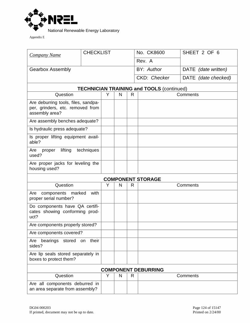
National Renewable Energy LaboratoryAppendix E
DG04 000203 Page 124 of 15147If printed, document may not be up to date. Printed on 2/24/00
No. CK8600Company Name CHECKLIST
Rev. A
SHEET 2 OF 6
BY: Author DATE (date written)Gearbox Assembly
CKD: Checker DATE (date checked)
TECHNICIAN TRAINING and TOOLS (continued)Question Y N R Comments
Are deburring tools, files, sandpa-per, grinders, etc. removed fromassembly area?
Are assembly benches adequate?
Is hydraulic press adequate?
Is proper lifting equipment avail-able?
Are proper lifting techniquesused?
Are proper jacks for leveling thehousing used?
COMPONENT STORAGEQuestion Y N R Comments
Are components marked withproper serial number?
Do components have QA certifi-cates showing conforming prod-uct?
Are components properly stored?
Are components covered?
Are bearings stored on theirsides?
Are lip seals stored separately inboxes to protect them?
COMPONENT DEBURRINGQuestion Y N R Comments
Are all components deburred inan area separate from assembly?

National Renewable Energy LaboratoryAppendix E
DG04 000203 Page 125 of 15147If printed, document may not be up to date. Printed on 2/24/00
No. CK8600Company Name CHECKLIST
Rev. A
SHEET 3 OF 6
BY: Author DATE (date written)Gearbox Assembly
CKD: Checker DATE (date checked)
COMPONENT DEBURRING (continued)Question Y N R Comments
Are gear housings deburred inseparate area?
Do all gear teeth have adequatetip, edge, and end rounds?
Do all shaft journals have ade-quate chamfers?
Do all bearing caps have ade-quate puller holes?
Do all threaded holes have ade-quate chamfers?
COMPONENT CLEANINGQuestion Y N R Comments
Are all components cleaned inarea separate from assembly?
Are gear housings cleaned inseparate area?
Are solvent tanks adequate?
Is cleaning fluid proper?
Are rags lint free?
Are all drilled holes clean?
Are all threaded holes clean?
HOUSEKEEPINGQuestion Y N R Comments
Has assembly area been vac-uumed before assembly starts?
Are gear housings vacuumed be-fore assembly?
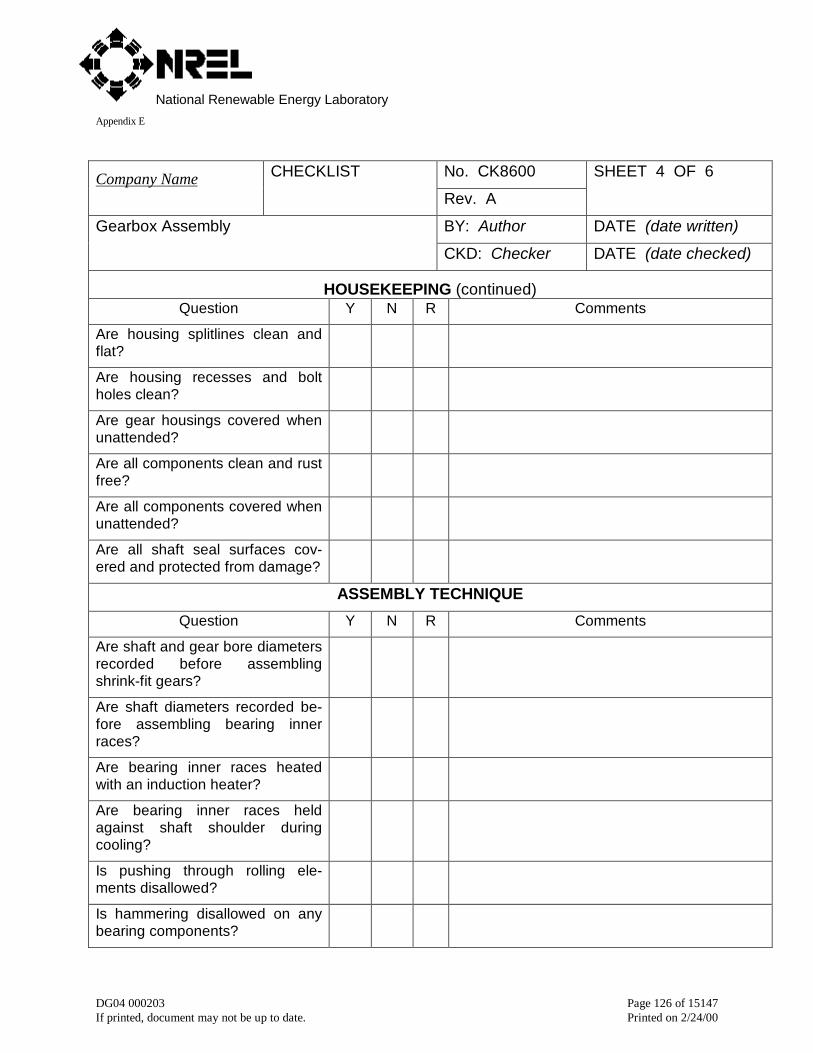
National Renewable Energy LaboratoryAppendix E
DG04 000203 Page 126 of 15147If printed, document may not be up to date. Printed on 2/24/00
No. CK8600Company Name CHECKLIST
Rev. A
SHEET 4 OF 6
BY: Author DATE (date written)Gearbox Assembly
CKD: Checker DATE (date checked)
HOUSEKEEPING (continued)Question Y N R Comments
Are housing splitlines clean andflat?
Are housing recesses and boltholes clean?
Are gear housings covered whenunattended?
Are all components clean and rustfree?
Are all components covered whenunattended?
Are all shaft seal surfaces cov-ered and protected from damage?
ASSEMBLY TECHNIQUE
Question Y N R Comments
Are shaft and gear bore diametersrecorded before assemblingshrink-fit gears?
Are shaft diameters recorded be-fore assembling bearing innerraces?
Are bearing inner races heatedwith an induction heater?
Are bearing inner races heldagainst shaft shoulder duringcooling?
Is pushing through rolling ele-ments disallowed?
Is hammering disallowed on anybearing components?
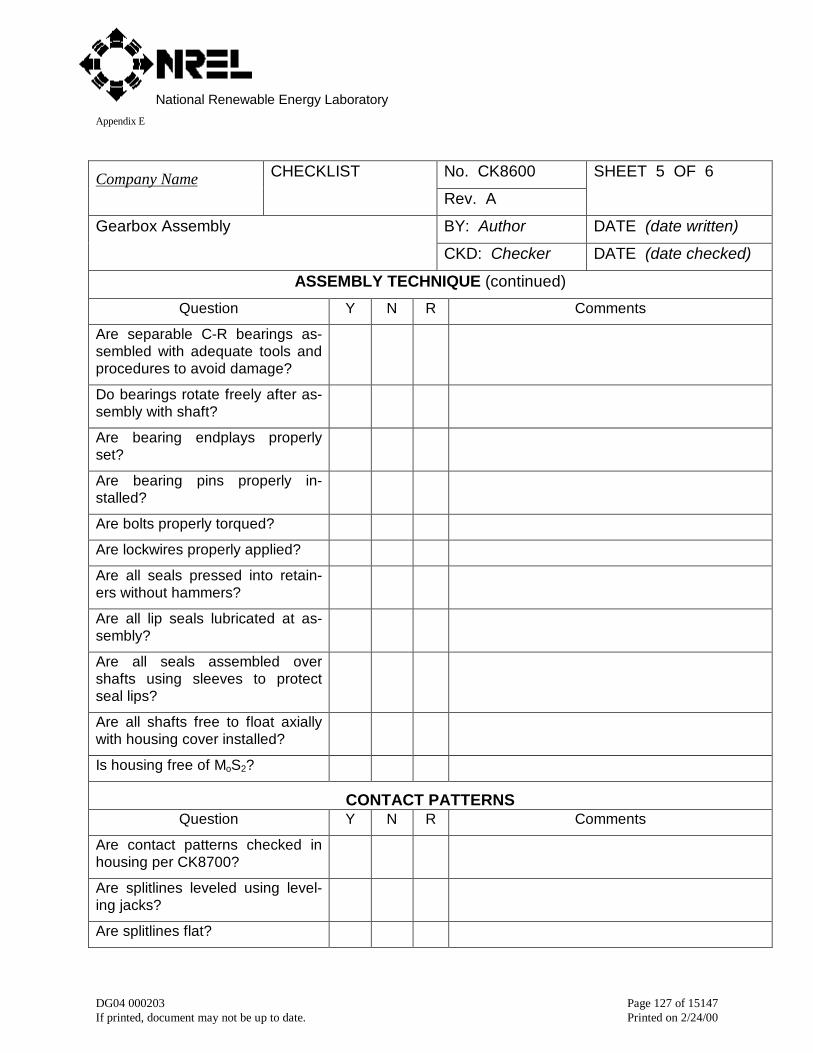
National Renewable Energy LaboratoryAppendix E
DG04 000203 Page 127 of 15147If printed, document may not be up to date. Printed on 2/24/00
No. CK8600Company Name CHECKLIST
Rev. A
SHEET 5 OF 6
BY: Author DATE (date written)Gearbox Assembly
CKD: Checker DATE (date checked)
ASSEMBLY TECHNIQUE (continued)
Question Y N R Comments
Are separable C-R bearings as-sembled with adequate tools andprocedures to avoid damage?
Do bearings rotate freely after as-sembly with shaft?
Are bearing endplays properlyset?
Are bearing pins properly in-stalled?
Are bolts properly torqued?
Are lockwires properly applied?
Are all seals pressed into retain-ers without hammers?
Are all lip seals lubricated at as-sembly?
Are all seals assembled overshafts using sleeves to protectseal lips?
Are all shafts free to float axiallywith housing cover installed?
Is housing free of MoS2?
CONTACT PATTERNSQuestion Y N R Comments
Are contact patterns checked inhousing per CK8700?
Are splitlines leveled using level-ing jacks?
Are splitlines flat?

National Renewable Energy LaboratoryAppendix E
DG04 000203 Page 128 of 15147If printed, document may not be up to date. Printed on 2/24/00
No. CK8600Company Name CHECKLIST
Rev. A
SHEET 6 OF 6
BY: Author DATE (date written)Gearbox Assembly
CKD: Checker DATE (date checked)
CONTACT PATTERNS (continued)Question Y N R Comments
Is marking compound clean andproperly applied?
Are covers installed before con-tact pattern testing?
Are dowel pins installed?
Are gears rolled with light torque?
Is cover removed for inspection?
Are patterns documented withtapes?
Is marking compound removed?
Is DYKEM tested for compatibilitywith lubricant?
Is DYKEM properly applied?
Are covers installed using sealantsparingly?
PREPARATION FOR TESTING
Question Y N R Comments
Are all gear housing openingssealed?
Do all gearsets have adequatebacklash?
Do lube system componentsconform to lube schematic?
Are guidelines for tests being fol-lowed?
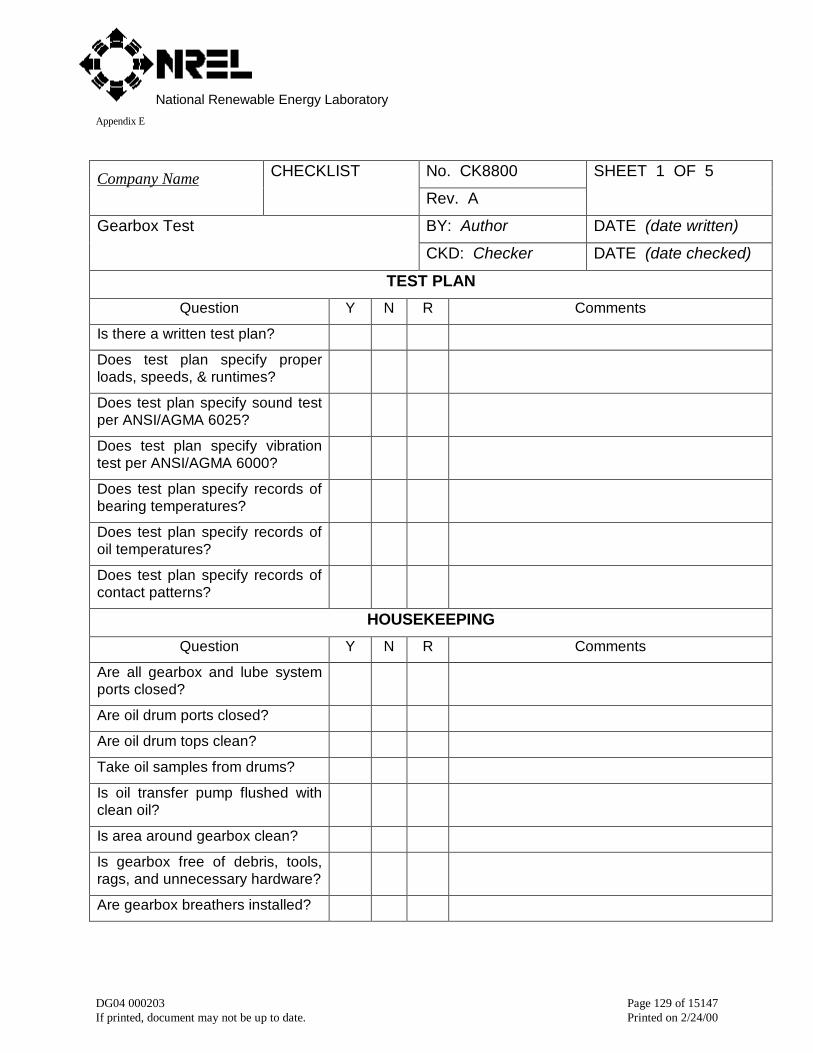
National Renewable Energy LaboratoryAppendix E
DG04 000203 Page 129 of 15147If printed, document may not be up to date. Printed on 2/24/00
No. CK8800Company Name CHECKLIST
Rev. A
SHEET 1 OF 5
BY: Author DATE (date written)Gearbox Test
CKD: Checker DATE (date checked)
TEST PLAN
Question Y N R Comments
Is there a written test plan?
Does test plan specify properloads, speeds, & runtimes?
Does test plan specify sound testper ANSI/AGMA 6025?
Does test plan specify vibrationtest per ANSI/AGMA 6000?
Does test plan specify records ofbearing temperatures?
Does test plan specify records ofoil temperatures?
Does test plan specify records ofcontact patterns?
HOUSEKEEPING
Question Y N R Comments
Are all gearbox and lube systemports closed?
Are oil drum ports closed?
Are oil drum tops clean?
Take oil samples from drums?
Is oil transfer pump flushed withclean oil?
Is area around gearbox clean?
Is gearbox free of debris, tools,rags, and unnecessary hardware?
Are gearbox breathers installed?
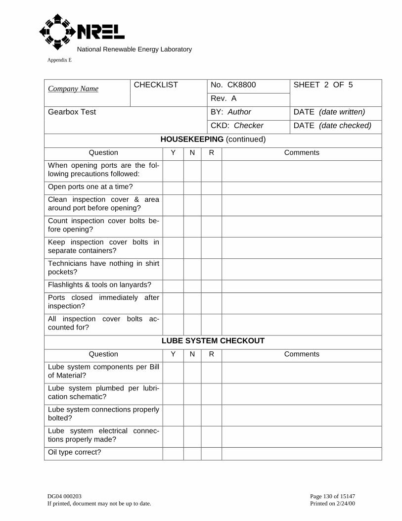
National Renewable Energy LaboratoryAppendix E
DG04 000203 Page 130 of 15147If printed, document may not be up to date. Printed on 2/24/00
No. CK8800Company Name CHECKLIST
Rev. A
SHEET 2 OF 5
BY: Author DATE (date written)Gearbox Test
CKD: Checker DATE (date checked)
HOUSEKEEPING (continued)
Question Y N R Comments
When opening ports are the fol-lowing precautions followed:
Open ports one at a time?
Clean inspection cover & areaaround port before opening?
Count inspection cover bolts be-fore opening?
Keep inspection cover bolts inseparate containers?
Technicians have nothing in shirtpockets?
Flashlights & tools on lanyards?
Ports closed immediately afterinspection?
All inspection cover bolts ac-counted for?
LUBE SYSTEM CHECKOUT
Question Y N R Comments
Lube system components per Billof Material?
Lube system plumbed per lubri-cation schematic?
Lube system connections properlybolted?
Lube system electrical connec-tions properly made?
Oil type correct?
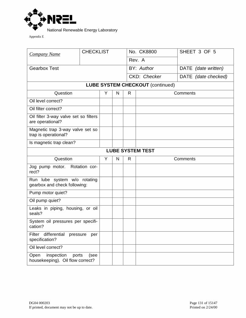
National Renewable Energy LaboratoryAppendix E
DG04 000203 Page 131 of 15147If printed, document may not be up to date. Printed on 2/24/00
No. CK8800Company Name CHECKLIST
Rev. A
SHEET 3 OF 5
BY: Author DATE (date written)Gearbox Test
CKD: Checker DATE (date checked)
LUBE SYSTEM CHECKOUT (continued)
Question Y N R Comments
Oil level correct?
Oil filter correct?
Oil filter 3-way valve set so filtersare operational?
Magnetic trap 3-way valve set sotrap is operational?
Is magnetic trap clean?
LUBE SYSTEM TEST
Question Y N R Comments
Jog pump motor. Rotation cor-rect?
Run lube system w/o rotatinggearbox and check following:
Pump motor quiet?
Oil pump quiet?
Leaks in piping, housing, or oilseals?
System oil pressures per specifi-cation?
Filter differential pressure perspecification?
Oil level correct?
Open inspection ports (seehousekeeping). Oil flow correct?
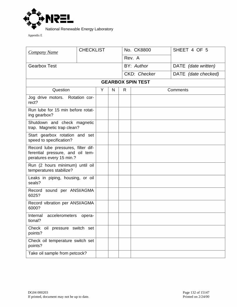
National Renewable Energy LaboratoryAppendix E
DG04 000203 Page 132 of 15147If printed, document may not be up to date. Printed on 2/24/00
No. CK8800Company Name CHECKLIST
Rev. A
SHEET 4 OF 5
BY: Author DATE (date written)Gearbox Test
CKD: Checker DATE (date checked)
GEARBOX SPIN TEST
Question Y N R Comments
Jog drive motors. Rotation cor-rect?
Run lube for 15 min before rotat-ing gearbox?
Shutdown and check magnetictrap. Magnetic trap clean?
Start gearbox rotation and setspeed to specification?
Record lube pressures, filter dif-ferential pressure, and oil tem-peratures every 15 min.?
Run (2 hours minimum) until oiltemperatures stabilize?
Leaks in piping, housing, or oilseals?
Record sound per ANSI/AGMA6025?
Record vibration per ANSI/AGMA6000?
Internal accelerometers opera-tional?
Check oil pressure switch setpoints?
Check oil temperature switch setpoints?
Take oil sample from petcock?
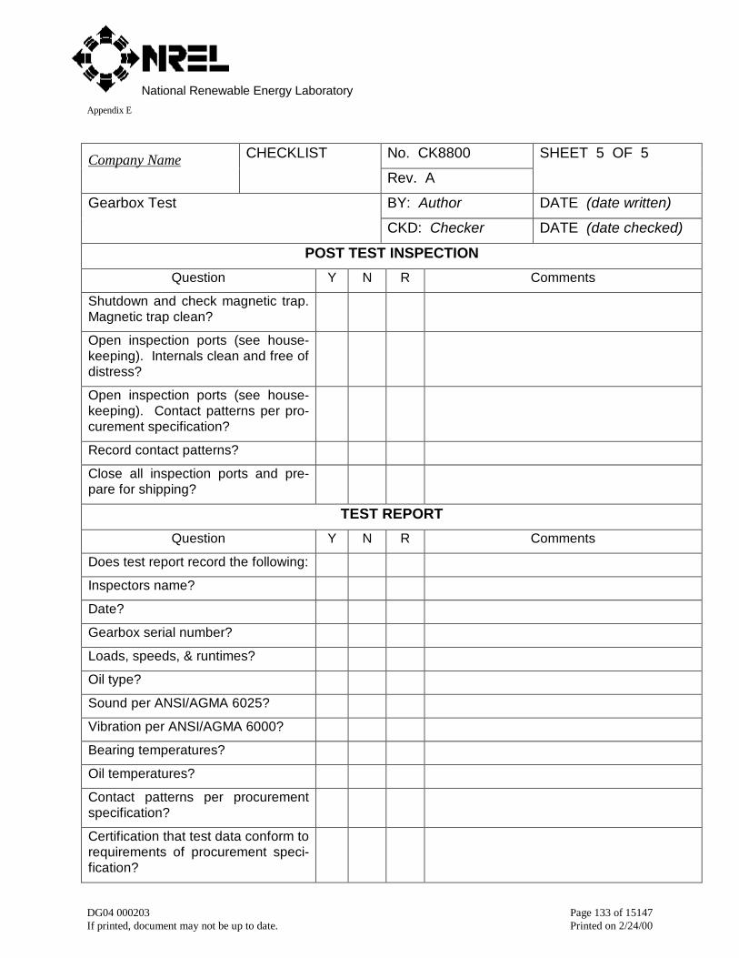
National Renewable Energy LaboratoryAppendix E
DG04 000203 Page 133 of 15147If printed, document may not be up to date. Printed on 2/24/00
No. CK8800Company Name CHECKLIST
Rev. A
SHEET 5 OF 5
BY: Author DATE (date written)Gearbox Test
CKD: Checker DATE (date checked)
POST TEST INSPECTION
Question Y N R Comments
Shutdown and check magnetic trap.Magnetic trap clean?
Open inspection ports (see house-keeping). Internals clean and free ofdistress?
Open inspection ports (see house-keeping). Contact patterns per pro-curement specification?
Record contact patterns?
Close all inspection ports and pre-pare for shipping?
TEST REPORT
Question Y N R Comments
Does test report record the following:
Inspectors name?
Date?
Gearbox serial number?
Loads, speeds, & runtimes?
Oil type?
Sound per ANSI/AGMA 6025?
Vibration per ANSI/AGMA 6000?
Bearing temperatures?
Oil temperatures?
Contact patterns per procurementspecification?
Certification that test data conform torequirements of procurement speci-fication?

National Renewable Energy LaboratoryAppendix E
DG04 000203 Page 134 of 15147If printed, document may not be up to date. Printed on 2/24/00
No. CK9101Company Name CHECKLIST
Rev. A
SHEET 1 OF 14
BY: Author DATE (date written)Gear System Audit
CKD: Checker DATE (date checked)
APPLICATION DATA
Question Y N R Comments
Customer?
Site?
Type of application?
Audit conducted by?
Date of audit?
Other?
DOCUMENTATION
Question Y N R Comments
Documents available?
Installation drawing?
Assembly drawing of gearbox?
Lubrication schematic?
Lube system bill of material?
Maintenance manual?
Service history?
Oil lab analyses?
Oil change interval records?
Filter change interval records?
Alignment records?
Vibration records?
Sound records?
Temperature records?
Other documents?
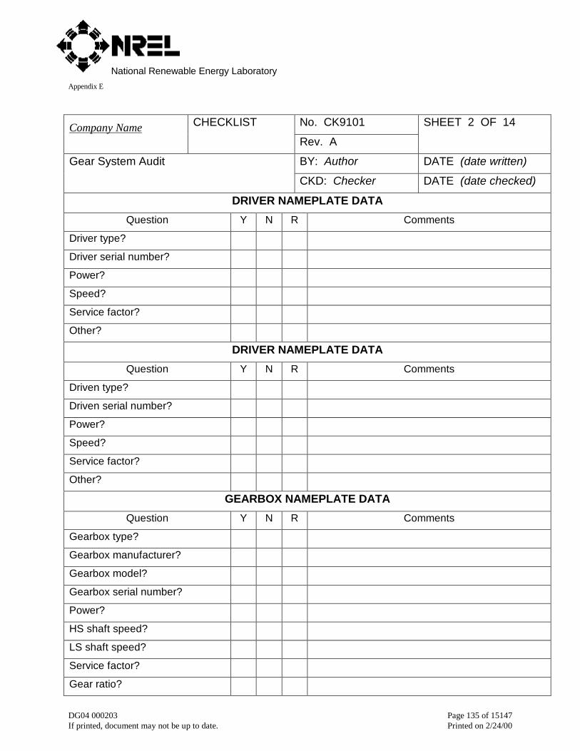
National Renewable Energy LaboratoryAppendix E
DG04 000203 Page 135 of 15147If printed, document may not be up to date. Printed on 2/24/00
No. CK9101Company Name CHECKLIST
Rev. A
SHEET 2 OF 14
BY: Author DATE (date written)Gear System Audit
CKD: Checker DATE (date checked)
DRIVER NAMEPLATE DATA
Question Y N R Comments
Driver type?
Driver serial number?
Power?
Speed?
Service factor?
Other?
DRIVER NAMEPLATE DATA
Question Y N R Comments
Driven type?
Driven serial number?
Power?
Speed?
Service factor?
Other?
GEARBOX NAMEPLATE DATA
Question Y N R Comments
Gearbox type?
Gearbox manufacturer?
Gearbox model?
Gearbox serial number?
Power?
HS shaft speed?
LS shaft speed?
Service factor?
Gear ratio?
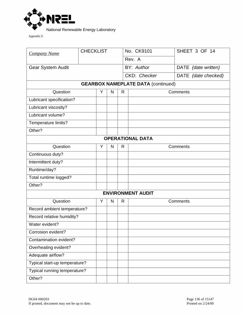
National Renewable Energy LaboratoryAppendix E
DG04 000203 Page 136 of 15147If printed, document may not be up to date. Printed on 2/24/00
No. CK9101Company Name CHECKLIST
Rev. A
SHEET 3 OF 14
BY: Author DATE (date written)Gear System Audit
CKD: Checker DATE (date checked)
GEARBOX NAMEPLATE DATA (continued)
Question Y N R Comments
Lubricant specification?
Lubricant viscosity?
Lubricant volume?
Temperature limits?
Other?
OPERATIONAL DATA
Question Y N R Comments
Continuous duty?
Intermittent duty?
Runtime/day?
Total runtime logged?
Other?
ENVIRONMENT AUDIT
Question Y N R Comments
Record ambient temperature?
Record relative humidity?
Water evident?
Corrosion evident?
Contamination evident?
Overheating evident?
Adequate airflow?
Typical start-up temperature?
Typical running temperature?
Other?

National Renewable Energy LaboratoryAppendix E
DG04 000203 Page 137 of 15147If printed, document may not be up to date. Printed on 2/24/00
No. CK9101Company Name CHECKLIST
Rev. A
SHEET 4 OF 14
BY: Author DATE (date written)Gear System Audit
CKD: Checker DATE (date checked)
FOUNDATION AUDIT
Question Y N R Comments
Baseplate solid?
Mounting bolts tight?
Driver shimmed properly?
Gearbox shimmed properly?
Driven shimmed properly?
Other?
ALIGHNMENT AUDIT
Question Y N R Comments
Couplings per installation draw-ing?
HS coupling type?
LS coupling type?
Date of last alignment?
HS coupling alignment data?
LS coupling alignment data?
Coupling lubricant per spec?
Date lube last changed?
Other?
LUBRICATION SYSTEM AUDIT
Question Y N R Comments
Lube system components per Billof Material?
Lube system plumbed per lubri-cation schematic?
Lube system connections prop-erly bolted?
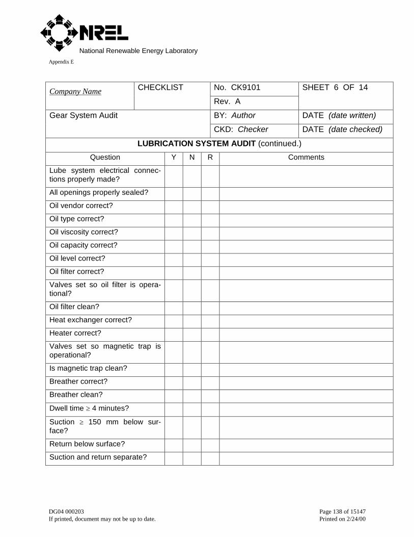
National Renewable Energy LaboratoryAppendix E
DG04 000203 Page 138 of 15147If printed, document may not be up to date. Printed on 2/24/00
No. CK9101Company Name CHECKLIST
Rev. A
SHEET 6 OF 14
BY: Author DATE (date written)Gear System Audit
CKD: Checker DATE (date checked)
LUBRICATION SYSTEM AUDIT (continued.)
Question Y N R Comments
Lube system electrical connec-tions properly made?
All openings properly sealed?
Oil vendor correct?
Oil type correct?
Oil viscosity correct?
Oil capacity correct?
Oil level correct?
Oil filter correct?
Valves set so oil filter is opera-tional?
Oil filter clean?
Heat exchanger correct?
Heater correct?
Valves set so magnetic trap isoperational?
Is magnetic trap clean?
Breather correct?
Breather clean?
Dwell time ≥ 4 minutes?
Suction ≥ 150 mm below sur-face?
Return below surface?
Suction and return separate?
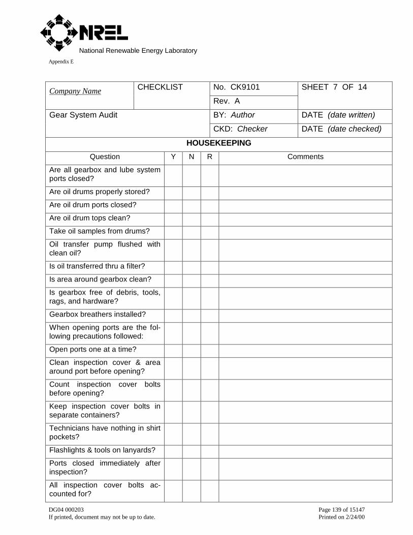
National Renewable Energy LaboratoryAppendix E
DG04 000203 Page 139 of 15147If printed, document may not be up to date. Printed on 2/24/00
No. CK9101Company Name CHECKLIST
Rev. A
SHEET 7 OF 14
BY: Author DATE (date written)Gear System Audit
CKD: Checker DATE (date checked)
HOUSEKEEPING
Question Y N R Comments
Are all gearbox and lube systemports closed?
Are oil drums properly stored?
Are oil drum ports closed?
Are oil drum tops clean?
Take oil samples from drums?
Oil transfer pump flushed withclean oil?
Is oil transferred thru a filter?
Is area around gearbox clean?
Is gearbox free of debris, tools,rags, and hardware?
Gearbox breathers installed?
When opening ports are the fol-lowing precautions followed:
Open ports one at a time?
Clean inspection cover & areaaround port before opening?
Count inspection cover boltsbefore opening?
Keep inspection cover bolts inseparate containers?
Technicians have nothing in shirtpockets?
Flashlights & tools on lanyards?
Ports closed immediately afterinspection?
All inspection cover bolts ac-counted for?
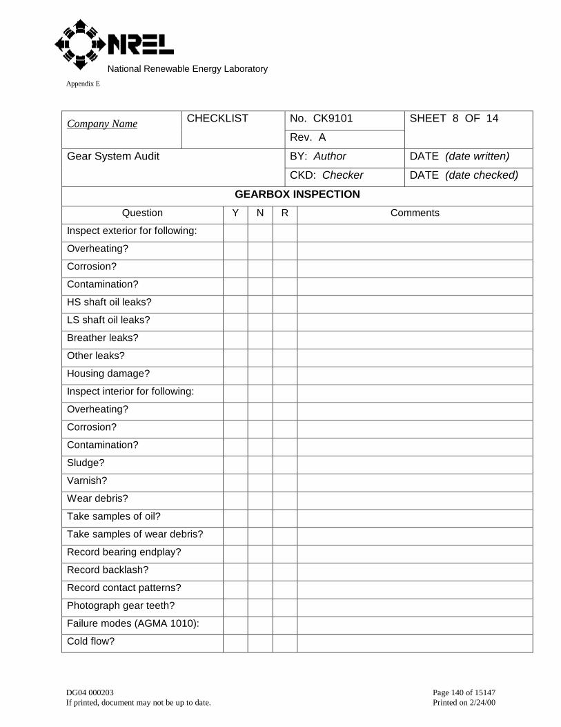
National Renewable Energy LaboratoryAppendix E
DG04 000203 Page 140 of 15147If printed, document may not be up to date. Printed on 2/24/00
No. CK9101Company Name CHECKLIST
Rev. A
SHEET 8 OF 14
BY: Author DATE (date written)Gear System Audit
CKD: Checker DATE (date checked)
GEARBOX INSPECTION
Question Y N R Comments
Inspect exterior for following:
Overheating?
Corrosion?
Contamination?
HS shaft oil leaks?
LS shaft oil leaks?
Breather leaks?
Other leaks?
Housing damage?
Inspect interior for following:
Overheating?
Corrosion?
Contamination?
Sludge?
Varnish?
Wear debris?
Take samples of oil?
Take samples of wear debris?
Record bearing endplay?
Record backlash?
Record contact patterns?
Photograph gear teeth?
Failure modes (AGMA 1010):
Cold flow?
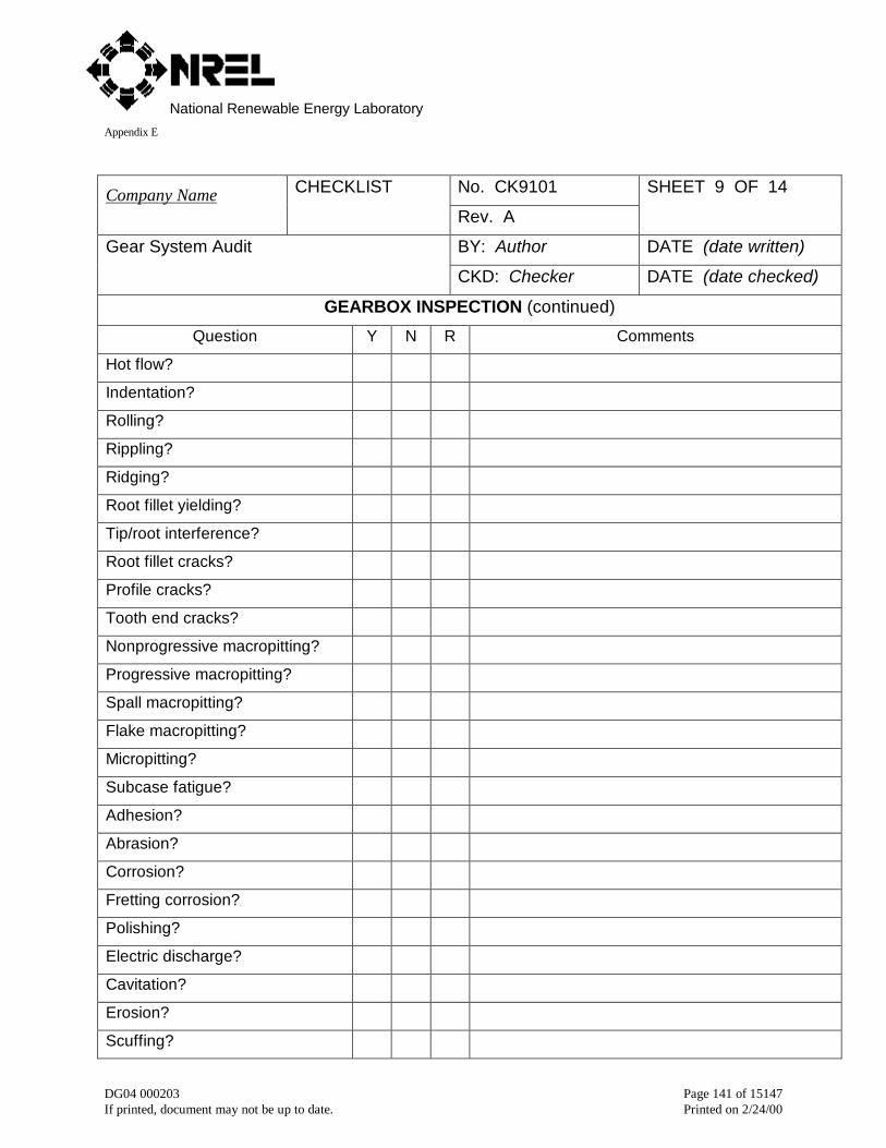
National Renewable Energy LaboratoryAppendix E
DG04 000203 Page 141 of 15147If printed, document may not be up to date. Printed on 2/24/00
No. CK9101Company Name CHECKLIST
Rev. A
SHEET 9 OF 14
BY: Author DATE (date written)Gear System Audit
CKD: Checker DATE (date checked)
GEARBOX INSPECTION (continued)
Question Y N R Comments
Hot flow?
Indentation?
Rolling?
Rippling?
Ridging?
Root fillet yielding?
Tip/root interference?
Root fillet cracks?
Profile cracks?
Tooth end cracks?
Nonprogressive macropitting?
Progressive macropitting?
Spall macropitting?
Flake macropitting?
Micropitting?
Subcase fatigue?
Adhesion?
Abrasion?
Corrosion?
Fretting corrosion?
Polishing?
Electric discharge?
Cavitation?
Erosion?
Scuffing?
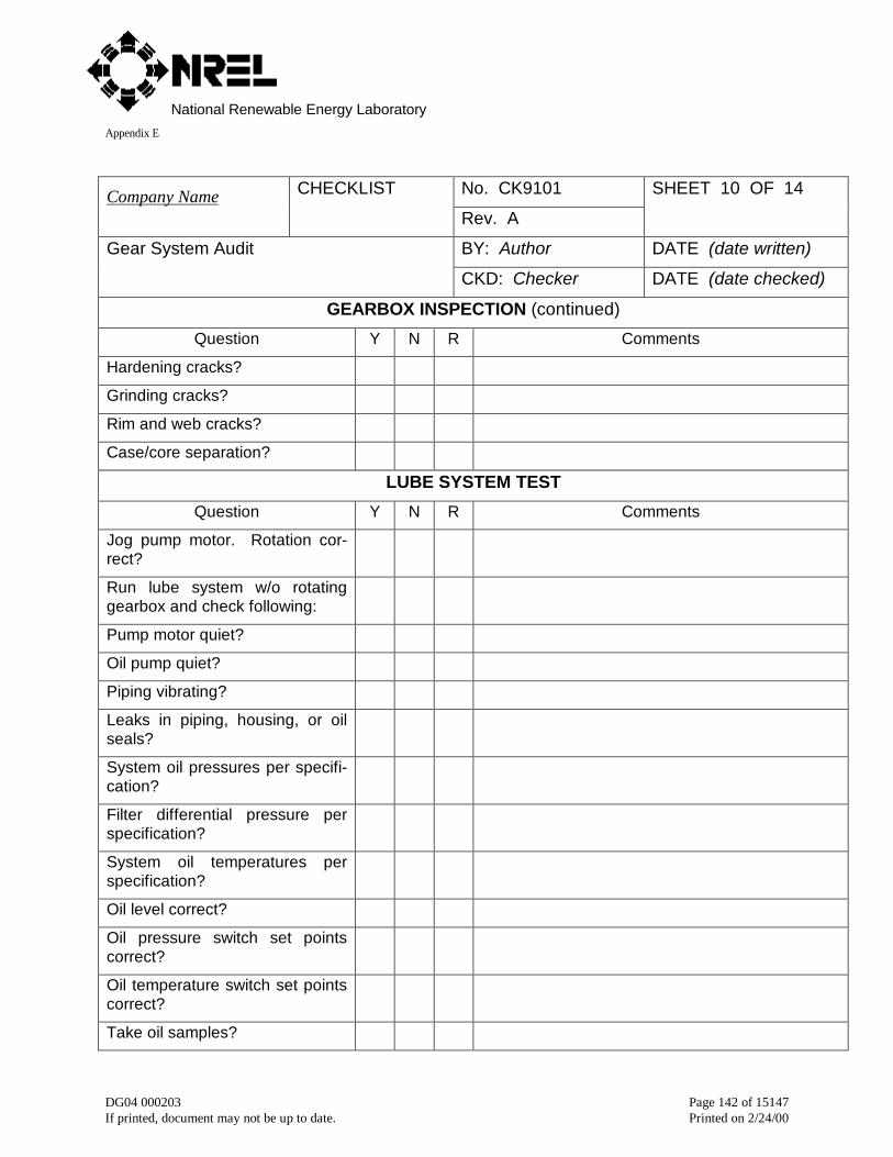
National Renewable Energy LaboratoryAppendix E
DG04 000203 Page 142 of 15147If printed, document may not be up to date. Printed on 2/24/00
No. CK9101Company Name CHECKLIST
Rev. A
SHEET 10 OF 14
BY: Author DATE (date written)Gear System Audit
CKD: Checker DATE (date checked)
GEARBOX INSPECTION (continued)
Question Y N R Comments
Hardening cracks?
Grinding cracks?
Rim and web cracks?
Case/core separation?
LUBE SYSTEM TEST
Question Y N R Comments
Jog pump motor. Rotation cor-rect?
Run lube system w/o rotatinggearbox and check following:
Pump motor quiet?
Oil pump quiet?
Piping vibrating?
Leaks in piping, housing, or oilseals?
System oil pressures per specifi-cation?
Filter differential pressure perspecification?
System oil temperatures perspecification?
Oil level correct?
Oil pressure switch set pointscorrect?
Oil temperature switch set pointscorrect?
Take oil samples?
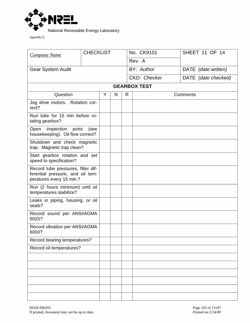
National Renewable Energy LaboratoryAppendix E
DG04 000203 Page 143 of 15147If printed, document may not be up to date. Printed on 2/24/00
No. CK9101Company Name CHECKLIST
Rev. A
SHEET 11 OF 14
BY: Author DATE (date written)Gear System Audit
CKD: Checker DATE (date checked)
GEARBOX TEST
Question Y N R Comments
Jog drive motors. Rotation cor-rect?
Run lube for 15 min before ro-tating gearbox?
Open inspection ports (seehousekeeping). Oil flow correct?
Shutdown and check magnetictrap. Magnetic trap clean?
Start gearbox rotation and setspeed to specification?
Record lube pressures, filter dif-ferential pressure, and oil tem-peratures every 15 min.?
Run (2 hours minimum) until oiltemperatures stabilize?
Leaks in piping, housing, or oilseals?
Record sound per ANSI/AGMA6025?
Record vibration per ANSI/AGMA6000?
Record bearing temperatures?
Record oil temperatures?
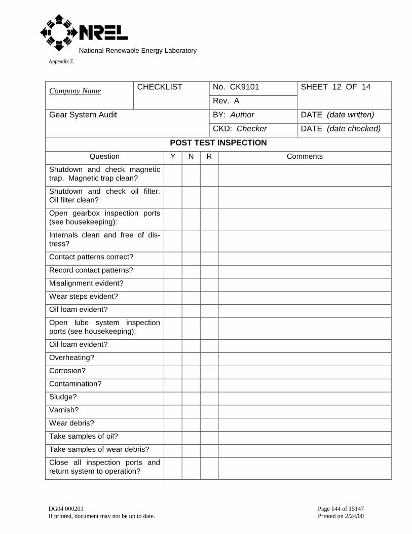
National Renewable Energy LaboratoryAppendix E
DG04 000203 Page 144 of 15147If printed, document may not be up to date. Printed on 2/24/00
No. CK9101Company Name CHECKLIST
Rev. A
SHEET 12 OF 14
BY: Author DATE (date written)Gear System Audit
CKD: Checker DATE (date checked)
POST TEST INSPECTION
Question Y N R Comments
Shutdown and check magnetictrap. Magnetic trap clean?
Shutdown and check oil filter.Oil filter clean?
Open gearbox inspection ports(see housekeeping):
Internals clean and free of dis-tress?
Contact patterns correct?
Record contact patterns?
Misalignment evident?
Wear steps evident?
Oil foam evident?
Open lube system inspectionports (see housekeeping):
Oil foam evident?
Overheating?
Corrosion?
Contamination?
Sludge?
Varnish?
Wear debris?
Take samples of oil?
Take samples of wear debris?
Close all inspection ports andreturn system to operation?
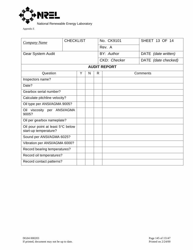
National Renewable Energy LaboratoryAppendix E
DG04 000203 Page 145 of 15147If printed, document may not be up to date. Printed on 2/24/00
No. CK9101Company Name CHECKLIST
Rev. A
SHEET 13 OF 14
BY: Author DATE (date written)Gear System Audit
CKD: Checker DATE (date checked)
AUDIT REPORT
Question Y N R Comments
Inspectors name?
Date?
Gearbox serial number?
Calculate pitchline velocity?
Oil type per ANSI/AGMA 9005?
Oil viscosity per ANSI/AGMA9005?
Oil per gearbox nameplate?
Oil pour point at least 5°C belowstart-up temperature?
Sound per ANSI/AGMA 6025?
Vibration per ANSI/AGMA 6000?
Record bearing temperatures?
Record oil temperatures?
Record contact patterns?
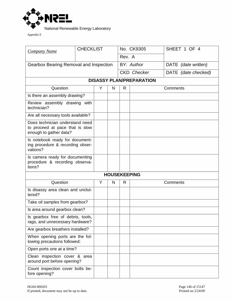
National Renewable Energy LaboratoryAppendix E
DG04 000203 Page 146 of 15147If printed, document may not be up to date. Printed on 2/24/00
No. CK9305Company Name CHECKLIST
Rev. A
SHEET 1 OF 4
BY: Author DATE (date written)Gearbox Bearing Removal and Inspection
CKD Checker DATE (date checked)
DISASSY PLAN/PREPARATION
Question Y N R Comments
Is there an assembly drawing?
Review assembly drawing withtechnician?
Are all necessary tools available?
Does technician understand needto proceed at pace that is slowenough to gather data?
Is notebook ready for document-ing procedure & recording obser-vations?
Is camera ready for documentingprocedure & recording observa-tions?
HOUSEKEEPING
Question Y N R Comments
Is disassy area clean and unclut-tered?
Take oil samples from gearbox?
Is area around gearbox clean?
Is gearbox free of debris, tools,rags, and unnecessary hardware?
Are gearbox breathers installed?
When opening ports are the fol-lowing precautions followed:
Open ports one at a time?
Clean inspection cover & areaaround port before opening?
Count inspection cover bolts be-fore opening?
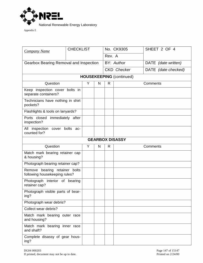
National Renewable Energy LaboratoryAppendix E
DG04 000203 Page 147 of 15147If printed, document may not be up to date. Printed on 2/24/00
No. CK9305Company Name CHECKLIST
Rev. A
SHEET 2 OF 4
BY: Author DATE (date written)Gearbox Bearing Removal and Inspection
CKD Checker DATE (date checked)
HOUSEKEEPING (continued)
Question Y N R Comments
Keep inspection cover bolts inseparate containers?
Technicians have nothing in shirtpockets?
Flashlights & tools on lanyards?
Ports closed immediately afterinspection?
All inspection cover bolts ac-counted for?
GEARBOX DISASSY
Question Y N R Comments
Match mark bearing retainer cap& housing?
Photograph bearing retainer cap?
Remove bearing retainer boltsfollowing housekeeping rules?
Photograph interior of bearingretainer cap?
Photograph visible parts of bear-ing?
Photograph wear debris?
Collect wear debris?
Match mark bearing outer raceand housing?
Match mark bearing inner raceand shaft?
Complete disassy of gear hous-ing?
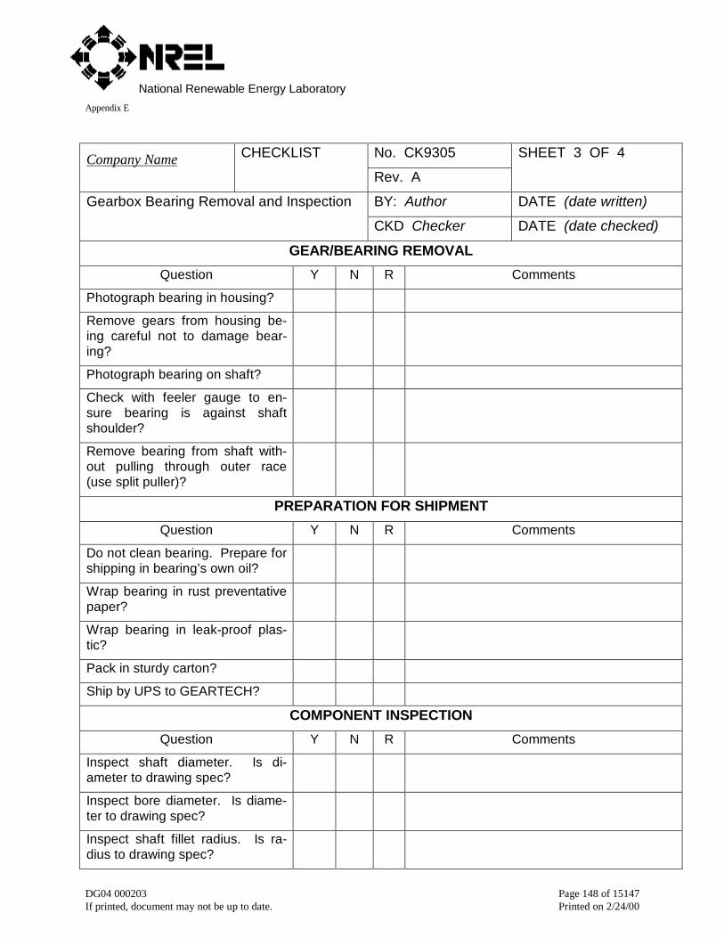
National Renewable Energy LaboratoryAppendix E
DG04 000203 Page 148 of 15147If printed, document may not be up to date. Printed on 2/24/00
No. CK9305Company Name CHECKLIST
Rev. A
SHEET 3 OF 4
BY: Author DATE (date written)Gearbox Bearing Removal and Inspection
CKD Checker DATE (date checked)
GEAR/BEARING REMOVAL
Question Y N R Comments
Photograph bearing in housing?
Remove gears from housing be-ing careful not to damage bear-ing?
Photograph bearing on shaft?
Check with feeler gauge to en-sure bearing is against shaftshoulder?
Remove bearing from shaft with-out pulling through outer race(use split puller)?
PREPARATION FOR SHIPMENT
Question Y N R Comments
Do not clean bearing. Prepare forshipping in bearing’s own oil?
Wrap bearing in rust preventativepaper?
Wrap bearing in leak-proof plas-tic?
Pack in sturdy carton?
Ship by UPS to GEARTECH?
COMPONENT INSPECTION
Question Y N R Comments
Inspect shaft diameter. Is di-ameter to drawing spec?
Inspect bore diameter. Is diame-ter to drawing spec?
Inspect shaft fillet radius. Is ra-dius to drawing spec?

National Renewable Energy LaboratoryAppendix E
DG04 000203 Page 149 of 15147If printed, document may not be up to date. Printed on 2/24/00
Does new bearing have properpart number?
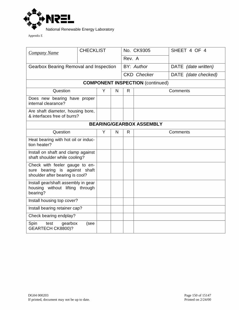
National Renewable Energy LaboratoryAppendix E
DG04 000203 Page 150 of 15147If printed, document may not be up to date. Printed on 2/24/00
No. CK9305Company Name CHECKLIST
Rev. A
SHEET 4 OF 4
BY: Author DATE (date written)Gearbox Bearing Removal and Inspection
CKD Checker DATE (date checked)
COMPONENT INSPECTION (continued)
Question Y N R Comments
Does new bearing have properinternal clearance?
Are shaft diameter, housing bore,& interfaces free of burrs?
BEARING/GEARBOX ASSEMBLY
Question Y N R Comments
Heat bearing with hot oil or induc-tion heater?
Install on shaft and clamp againstshaft shoulder while cooling?
Check with feeler gauge to en-sure bearing is against shaftshoulder after bearing is cool?
Install gear/shaft assembly in gearhousing without lifting throughbearing?
Install housing top cover?
Install bearing retainer cap?
Check bearing endplay?
Spin test gearbox (seeGEARTECH CK8800)?
National Renewable Energy LaboratoryAppendix E
DG04 000203 Page 151 of 15147If printed, document may not be up to date. Printed on 2/24/00
6 NREL ChecklistCertification auditors must have a clear guideline for the minimum information that should be included inthe design documentation of a gearbox. The basic requirements are set by standards but the certificationbody must translate those requirements into specific technical information. It is important for the designerto know what the auditor will be looking for so that he/she can make sure it is contained in the designdocumentation/specifications. The following form is a distillation of the checklists presented in section 7and is seen as assuring the minimum requirements set in the IEC standards are met. It is intended forauditors and designers.
6.1 DF16 Gearbox Evaluation