Embed Size (px)
Citation preview
ABSTRACTPiezoelectric wafer active sensors (PWAS) are lightweight and inexpensive transducers that enable a large class of structural health monitoring (SHM) applications such as: (a) embedded guided wave ultrasonics, i.e., pitch-catch, pulse-echo, phased arrays; (b) high-frequency modal sensing, i.e., electro-mechanical impedance method; and (c) passive detection. The focus of this paper is on the challenges posed by using PWAS transducers in the composite laminate structures as different from the metallic structures on which this methodology was initially developed. After a brief introduction, the paper reviews the PWAS-based SHM principles. It follows with a discussion of guided wave propagation in composites and PWAS tuning effects. Then, the mechanical effect is discussed on the integration of piezoelectric wafer inside the laminate using a compression after impact. Experiments were performed on a glass fiber laminate, employing PWAS to measure the attenuation coefficient. Finally, the paper presents some experimental and multi-physics finite element method (MP-FEM) results on guided wave propagation in composite laminate specimens.
AeronAuticAl JournAl october 2013 Volume 117 no 1196 971
Paper No. 3887. Manuscript received 17 July 2012, revised version received 22 March 2013, accepted 22 April 2013.
Guided wave propagation in composite laminates using piezoelectric wafer active sensorsM. Gresil [email protected]. GiurgiutiuDepartment of Mechanical Engineering University of South Carolina, Columbia South Carolina USA

972 the AeronAuticAl JournAl october 2013
NOMENCLATUREA0 first antisymmetric modeAk amplitude of the partial waves in the kth layer in the global matrix method[C] damping matrixDj electrical displacement vector, C/m2
dijkl piezoelectric coupling constant, m/VCijkl elasticity tensorC stiffness matrix of the composite layer in global co-ordinates, PaC' stiffness matrix of the composite layer in global co-ordinates, Pacc coefficient of critical dampingCg group velocity, ms–1
[Cp] piezoelectric stiffness matrixEk electric field tensor, V/mE1 axial modulus, PaE2 transverse modulus, Pa[ep] piezoelectric matrixf frequency, HzJ JouleskI attenuation coefficient of the viscoelastic medium, Np{F} force vector[K] stiffness matrix[Kd] dielectric conductivity.{KZ} piezoelectric coupling matrix{L} vector of nodal, surface and body charges[M] structural mass matrixS0 first symmetric modeSij mechanical strain tensor
SEijkl mechanical compliance under constant field, m2/N
t time, sTkl mechanical stress tensorUi displacement amplitudes, mu displacement, mun amplitude of vibration after n cycles{u} vector of nodal displacementvn velocity tensor for the nth guided wave mode, ms–1
{v} vector of electric potentialαm mass proportionality coefficientβk stiffness proportionality coefficientζ damping ratio[εp] dielectric matrix
εTjk dielectric permittivity under constant mechanical stress, F/m
ρ densityξ wave numberσij stress tensorω circular frequency, Hz
Gresil et al Guided wAVe propAGAtion in composite lAminAte mAteriAl usinG piezoelectric... 973
1.0 INTRODUCTIONStructural health monitoring (SHM) is an emerging technology with multiple applications in the evaluation of critical structures. The goal of SHM research is to develop a monitoring methodology that is capable of detecting and identifying, with minimal human intervention, various damage types during the service life of the structure.
In the literature, many publications dealing with the propagation of guided waves in a harmonic or transient excitation can be found. The simplest case concerns that of a healthy environment that is to say without damage, simple geometry, and made of homogeneous isotropic materials. This case was treated by classical such as Lamb(1) and Viktorov(2). Auld(3) used the method of superposition of partial waves to solve the Lamb waves problem. Other researchers have used other methods to describe the Lamb waves. Achenbach(4) determined the displacement compo-nents in terms of thickness motion superimposed on a membrane carrier wave which defines the propagation along the plate. The advantage of this technique is that the movement of the membrane can be determined independently. Achenbach and Xu(5) developed this technique for the case of a point source of harmonic pressure applied either to the surface or within a plate. This technique was also used for the case of an axisymmetric harmonic source(5). Hayachi and Endoh(6) calculated and visualised the propagation of Lamb waves using a hybrid method. Moreno et al(7) used the Fourier transform to study the propagation of a pressure pulse in an isotropic elastic plate. Other studies have been developed for the case of anisotropic media. Rose(8) treated the problem of the influence of the source on the propagation of Lamb waves in the three space directions. He used an analytical technique based on the asymptotic approximation to evaluate the far-field displacements in a composite plate. Nayfeh and Chimenti(9) studied the problem of Lamb waves dispersion curves in anisotropic plates, while Liand and Thompson(10) determined the Lamb waves dispersion curves in monoclinic symmetry and also for higher symmetries. All propagation media mentioned above are monolayers. However, in recent years, studies of multi-layer materials have also been developed. Nayfeh(11) used the transfer matrix method to solve the problem of propagation of Lamb waves in an anisotropic layered material. In a more recent article, Lowe(12) gives a summary review of existing techniques for modeling ultrasonic wave propagation in multilayer structures. This article also includes details of the transfer matrix and global matrix methods. Pierce et al(13) determined the characteristics of Lamb waves in the case of structures composed of layers of composite materials and hybrid type laser excitation. Liu et al(14) studied the case of the propagation of Lamb waves by multi-element transducers. As we can see, the list of research on the propagation, excitation and reception of Lamb waves is long and is far from exhaustive.
Guided waves open the way for SHM on long distance, with the hope of developing self-sensing structures of large dimensions without necessarily increasing the number of sensors and thus without increasing the complexity of the monitoring system.
For guided wave in composite laminate structure, there are advantages in using small piezo-electric wafer active sensors (PWAS) that can be embedded inside the laminate composite(15). In fact, there are two possibilities of integration PWAS transducers for SHM systems: (i) bonded on the composite structure; and (ii) embedded into the composite laminate structure. Besides the problems inherent in this integration, such as connectivity, the problem of integration raises two points that must be answered: (i) monitoring the integrity of the structure and sensors; and (ii) robustness of the method against anomalies in the integration of sensors. Indeed, the insertion of a foreign element in a host material has the immediate effect of locally modifying the mechanical behavior of the structure. It is therefore imperative to study the effect of the insertion of the sensor
974 the AeronAuticAl JournAl october 2013
on the mechanical properties of the structure and vice versa. Reference may be made to the thesis of Blanquet which focused exclusively in this study(16). On this subject, Lin and Chang(17)
conducted mechanical tests on the impact of integrating piezoelectric sensor network in the middle of a composite material. Bending tests, shear tests, short beam bending tests and compression tests were performed on different samples. These tests showed that there is no noticeable effect on the integrity of the structure(17). This proves that this system can be used without degrading the mechanical properties of the structure. However, to ensure that there is really no degradation, we conduct a study on the mechanical effect of such integration on compression after impact. Damages mechanisms in composite material subjected to impact are very complex and can be predicted by finite element(18). In this study, the goal is not to proposed a SHM system to detect and quantify the damaged due to impact but to study the effect of the insertion of PWAS trans-ducer in a composite material.
The present paper presents and discusses the challenges and opportunities related to the use of piezoelectric wafer active sensor (PWAS) transducers in generating and sensing guided waves in composite laminate structure. The multi-physics finite element method (MP-FEM) implementation allows for the consideration of the contributions of the active material, and the laminate structure. After a brief introduction, the paper reviews the PWAS-based SHM principles. It follows with a discussion of guided wave propagation in composites and PWAS tuning effects. Experiments were performed on a glass fiber laminate, employing PWAS to measure the attenuation based on the Rayleigh damping coefficients due to the viscoelasticity of the composite material. Finally, the paper presents some experimental and MP-FEM results on guided wave propagation in composite laminate specimens. The paper ends with summary and conclusion; suggestions for further work are also presented.
2.0 PIEZOELECTRIC WAFER ACTIVE SENSORS (PWAS)PWAS are the enabling technology for active SHM systems. PWAS couple the electrical and mechanical effects (mechanical strain, Sij, mechanical stress, Tkl electrical field, Ek, and electrical displacement Dj) through the tensorial piezoelectric constitutive equations:
. . . (1)
Where, SEijkl is the mechanical compliance of the material measured at zero electric field E = 0
εjk is the dielectric permittivity measured at zero mechanical stress T = 0, and djkl represents the piezoelectric coupling effect. PWAS utilise the d31 coupling between in-plane strains, S1, S2, and transverse electric field, E3. Just like conventional ultrasonic transducers, PWAS utilise the piezoelectric effect to generate and receive ultrasonic waves. However, PWAS are different from conventional ultrasonic transducers in several aspects(19):● PWAS are firmly coupled with the structure through an adhesive bonding, whereas conven-
tional ultrasonic transducers are weakly coupled through gel, water, or air.● PWAS are non-resonant devices that can be tuned selectively into several guided wave modes,
whereas conventional ultrasonic transducers are resonant narrow-band devices.● PWAS are inexpensive and can be deployed in large quantities on the structure, whereas
conventional ultrasonic transducers are expensive and used one at a time.
S s T d E
D d T Eij ijkl
Ekl kij k
j jkl kl jkT
k
ε
Gresil et al Guided wAVe propAGAtion in composite lAminAte mAteriAl usinG piezoelectric... 975
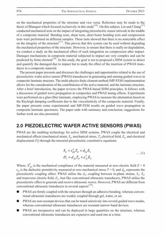
PWAS transducers can serve several purposes(19): (a) high-bandwidth strain sensors; (b) high-bandwidth wave exciters and receivers; (c) resonators; (d) embedded modal sensors with the electromechanical impedance spectroscopy method. By applications types, PWAS transducers can be used (Fig. 1) for (i) active sensing of far field damage using pulse-echo, pitch-catch, and phased-array methods, (ii) active sensing of near field damage using high frequency electromechanical impedance spectroscopy and thickness gage mode, and (iii) passive sensing of damage-generating events through detection of low-velocity impacts and acoustic emission at the tip of advancing cracks.
Figure 1. The various ways in which PWAS are used for structural sensing includes propagating Lamb waves, standing Lamb waves and phased arrays. The propagating waves method include: pitch-catch;
pulse-echo; thickness mode; and passive detection of impacts and acoustic emission(19).
976 the AeronAuticAl JournAl october 2013
3.0 THEORY OF GUIDED WAVE IN COMPOSITE MATERIALS
Different analytical methods depending on the studied material have been developed to describe the propagation of Lamb waves in sound structures. Almost all these techniques are based on the equations of motion(3):
. . . (2)
And the Hooke law(20):
. . . (3)
Where σij is the stress tensor, Cijkl the elasticity tensor, u the displacement field and ρ the density. The superscript ANA means analytical. In the case of isotropic plates, the dispersion curves can be drawn from the solution of the equation of Rayleigh-Lamb. For composite materials, there are different methods (transfer matrix, global matrix, stiffness matrix, etc.) that can be used to solve our problem. We used the transfer matrix applied to anisotropic composite plates(11). This method has the advantage of being stable for small values of frequency-thickness product (f × d).
We first consider a composite plate composed of orthotropic plies (Fig. 2). Assuming that each layer is made up of an orthotropic material with known properties, as defined by the layer stiffness matrix:
. . . (4)
Figure 2. Laminated composite plate model.
C '
' ' '
' ' '
' ' '
'
C C CC C CC C C
C
11 12 13
12 22 23
13 23 33
44
0 0 00 0 00 0 0
0 0 0 0 00 00 0 0 00 0 0 0 0
55
66
CC
'
'
2
2
ut xiANA
ijANA
j
ijANA
ijklkANA
l
lANA
k
C ux
ux
12
Gresil et al Guided wAVe propAGAtion in composite lAminAte mAteriAl usinG piezoelectric... 977
Or, explicitly:
Where:
The stiffness matrix in the global co-ordinate system is:
We assume the wave direction set at θ = 90°. Then the solution can be written as:
Where ξ is the wavenumber, v = ω/ξ is the phase velocity, ω is the circular frequency, α is an unknown parameter, and Ui is the displacement magnitude.The equation of motion is:
. . . (9)
. . . (5)
. . . (6)
. . . (7)
. . . (8)
C '
ν ν ν
ν ν
232
12
12 1 2 12 1 2
12 1 2 122
2 1
10 0 0
E E E E E
E E E E
ν ν
ν ν ν ν
122
2 23 1
12 1 2 122
2 23 1 122
2 1
0 0 0E E
E E E E E E
0 0 0
0 0 0 0 00 0 0 0 00 0 0 0 0
4
5
6
GG
G
E E E
1 23 122
22
23
1 21
ν νν
and
C
C C CC C CC C C
CC
11 12 13
12 11 13
13 13 33
44
55
0 0 00 0 00 0 0
0 0 0 0 00 0 0 0 00 0 0 0 00 66C
u u u U U U ei x x t1 2 3 1 2 3
1 3, , , ,
C ux
C ux
C C ux x
C C u11
21
12 66
21
32 12 66
22
1 213 55
23
xx xut
C ux
C ux
C ux
C C
1 3
212
66
22
12 22
22
22 44
22
32 23 44
23
2 3
222
13 55
21
1 323 44
22
2
ux x
ut
C C ux x
C C ux
xC u
xC u
xC u
xut3
55
23
12 44
23
22 33
23
32
232
978 the AeronAuticAl JournAl october 2013
Substituting Equation (7) into Equation (8), we have:
. . . (10)
Note that the direction 2 is not coupled with the other direction. This means that the shear horizontal (SH) wave would be decoupled from the other two modes of propagation.This system accepts non trivial solution if: . . . (11)
Following Nayfeh(11), we obtain the following formulation:
. . . (12)
With:
And: . . . (14)
Denote by P the left hand side of Equation (11), i.e. the vector that contains Equation (14), P, the displacements and stresses. Then denote by Xk the 4 × 4 matrix, by U the vector containing the Uli elements, and by D the diagonal matrix with .Thus Equation (11) can be written as: Pk = XkDkUk . . . (15)
Through this equation it is possible to link the displacements and the stresses of the bottom layer with those of the top layer. For the upper and lower layer of the kth layer we have, respectively: P– = Xk D
–k Uk
. . . (16) P+ = Xk D
+k Uk
Where D–k for the case where x3 = 0 and D+
k for x3 = dk. We can write: P+
k= Ak P–k . . . (17)
C C u C C u
C C u
C C
11 552 2
1 13 55 3
66 442 2
2
13 55
0
0
u C C u1 55 332 2
3 0
uu W W W W
D D D DD D
1
3
33
13
1 1 3 3
11 11 13 13
21 21
1 1 1 1
*
*
DD D
U e
U e
U
i x x t
i x x t
23 23
11
12
1
1 1 3
1 2 3
33
14
1 3 3
1 4 3
e
U e
i x x t
i x x t
α α41
22 0 A A
D C C W
D C Wq q q
q q q
1 13 33
2 55
. . . (13)
Wc C CC Cq
q
q
211 55
2
13 55
ei x x ti 1 3
Gresil et al Guided wAVe propAGAtion in composite lAminAte mAteriAl usinG piezoelectric... 979
Where: Ak = Xk Dk X
–1 k . . . (18)
Applying the above procedure for each layer, it is possible to relate the displacement and the stresses at the upper surface of the layered plate to those of the lower surface via the transfer matrix multiplication: ,..., A = An An-1 ,..., A1 . . . (19)
The total transfer matrix is:
. . . (20)
To obtain the dispersion curve we must impose stress-free conditions at the upper and lower surfaces, this leads to the characteristic equation: . . . (21)
4.0 EFFECT OF THE INSERTION OF A PIEZOELECTRIC WAFER IN LAMINATED COMPOSITE
For use in maintenance, the insertion of a SHM system in the composite structure during manufac-turing appears to be a major advancement in order to develop the multi-functional aspect. However many questions arise about the reliability over time of such a system. This is particularly the case for the connection, the reliability of sensors, and the possible influence of the latter, especially
u A AA A
uuu u
u
Au 0
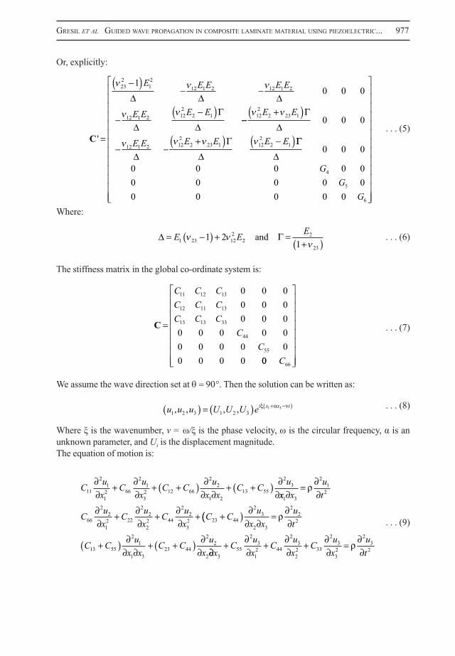
Figure 3. Compression after impact test (a) schematic; (b) configuration ASTM D 7137.
(a) (b)
980 the AeronAuticAl JournAl october 2013
piezoelectric wafer on the integrity of the structure. The following study examines the potential degradation initiation to damage by impact at low and relatively high energy.
To simulate the insertion of PWAS, a Teflon patch is embedded in the middle of the laminate during its infusion manufacturing. The influence of the patch diameter size is studied. Indeed, the defect introduced by the patch may play a role in the mechanism of damage within the glass plies. A correlation is attempted between the initial size of the insert and loss of mechanical performance residual post-impact. The reference test is the transverse compression test on a plate previously impacted (ASTM D 7137) (Figs 3(a) and 3(b)) to characterise the residual strength of an impacted structure. A comparison will be conducted between healthy material and with insert patch before and after impact.
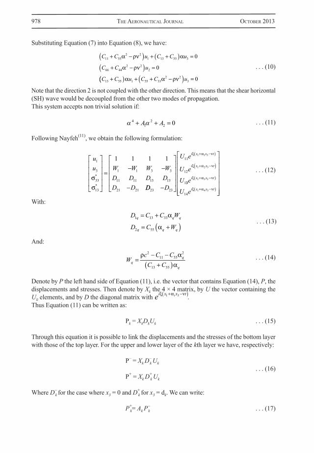
4.1 Compression after impactThe compression tests are carried out post-impact compression machine on quasi-static compression capacity of 150KN. The compression after impact method has been developed to simulate controlled defects or to characterise the damage following an impact. Several methods have been developed by various organisations. The best known of these is that created by the industry Boeing (Fig. 3(b)). This compression test allows you to easily identify the delamination in contrast to plane shear tests more difficult to achieve. This test corresponds to ASTM D 7137 (‘Standard Test Method for Residual Compression Strength Properties of Damaged Polymer Matrix Composite Plates’). This standard describes the method of impact test used prior to compression test and the specimen dimensions to use. The sides and bottom of the test piece are held by a same room. The sides are simply straight linear bearing, while the underside and the top of the test piece are embedded. The support of the sides of the test piece prevents buckling thereof. This is the moving part above that will ensure the compressive force. A prediction of the buckling mode associated with this load can be carried out by finite element modeling of the buckling. The Euler buckling modes considered show the presence of blisters that will be found in the tests. Indeed, the specimen undergoes, at the beginning of loading, a blister-type buckling (Fig. 4(a)), then abruptly changes in buckling shaped ‘S’ (Fig. 4(b)). This buckling could result in a change of boundary conditions in the intensity of loading on the specimen.
Figure 4. Buckling modes during ASTM D 7137 test; (a) beginning of loading, (b) middle and end of loading(15).
(a) (b)
Gresil et al Guided wAVe propAGAtion in composite lAminAte mAteriAl usinG piezoelectric... 981
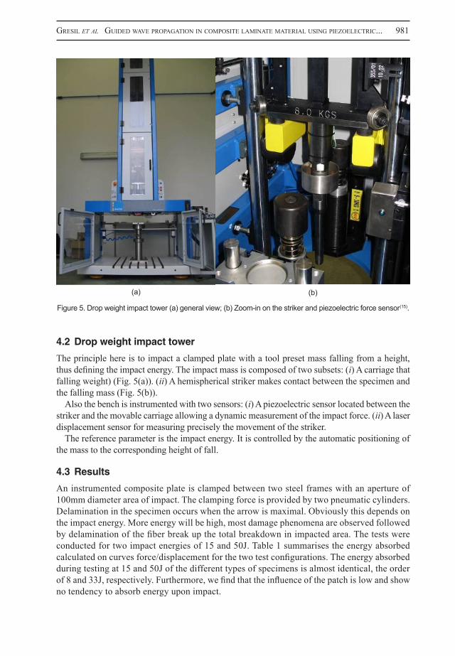
4.2 Drop weight impact tower
The principle here is to impact a clamped plate with a tool preset mass falling from a height, thus defining the impact energy. The impact mass is composed of two subsets: (i) A carriage that falling weight) (Fig. 5(a)). (ii) A hemispherical striker makes contact between the specimen and the falling mass (Fig. 5(b)).
Also the bench is instrumented with two sensors: (i) A piezoelectric sensor located between the striker and the movable carriage allowing a dynamic measurement of the impact force. (ii) A laser displacement sensor for measuring precisely the movement of the striker.
The reference parameter is the impact energy. It is controlled by the automatic positioning of the mass to the corresponding height of fall.
4.3 Results
An instrumented composite plate is clamped between two steel frames with an aperture of 100mm diameter area of impact. The clamping force is provided by two pneumatic cylinders. Delamination in the specimen occurs when the arrow is maximal. Obviously this depends on the impact energy. More energy will be high, most damage phenomena are observed followed by delamination of the fiber break up the total breakdown in impacted area. The tests were conducted for two impact energies of 15 and 50J. Table 1 summarises the energy absorbed calculated on curves force/displacement for the two test configurations. The energy absorbed during testing at 15 and 50J of the different types of specimens is almost identical, the order of 8 and 33J, respectively. Furthermore, we find that the influence of the patch is low and show no tendency to absorb energy upon impact.
Figure 5. Drop weight impact tower (a) general view; (b) Zoom-in on the striker and piezoelectric force sensor(15).
(a) (b)
982 the AeronAuticAl JournAl october 2013
Table 1Energy absorbed for different impact energies and different sizes of patch
Figure 6. Damage mechanisms of an impact composite laminated structure(21).
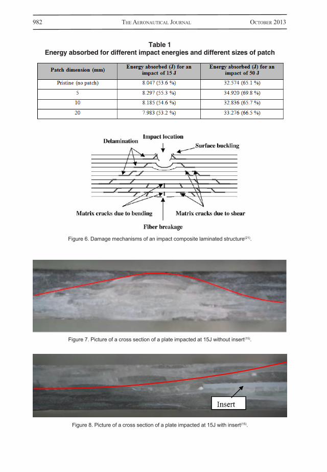
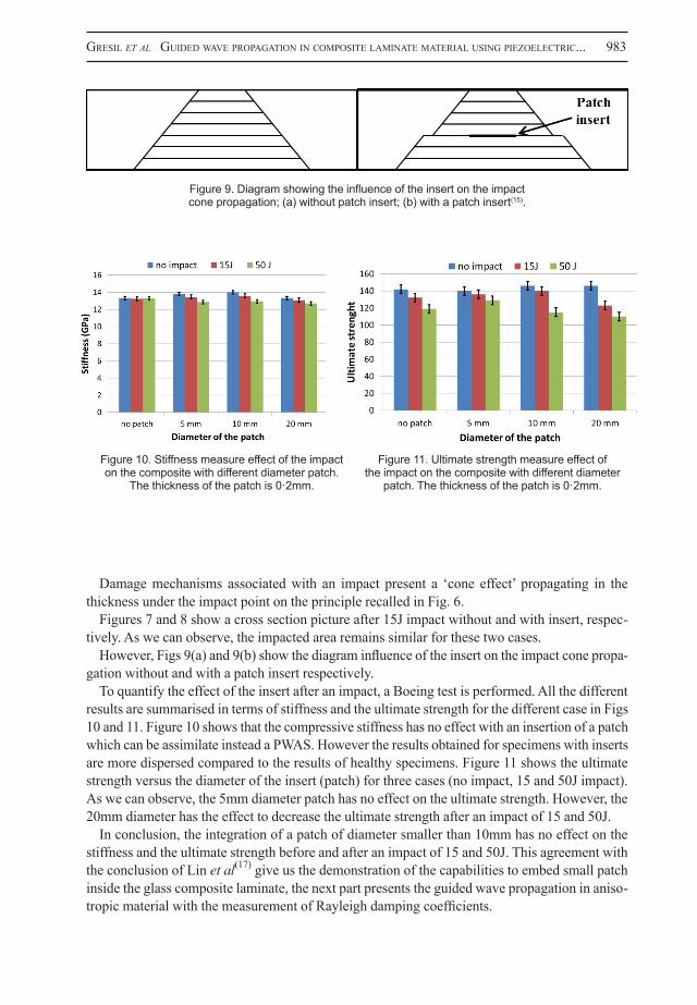
Figure 7. Picture of a cross section of a plate impacted at 15J without insert(15).
Figure 8. Picture of a cross section of a plate impacted at 15J with insert(15).
Gresil et al Guided wAVe propAGAtion in composite lAminAte mAteriAl usinG piezoelectric... 983
Damage mechanisms associated with an impact present a ‘cone effect’ propagating in the thickness under the impact point on the principle recalled in Fig. 6.
Figures 7 and 8 show a cross section picture after 15J impact without and with insert, respec-tively. As we can observe, the impacted area remains similar for these two cases.
However, Figs 9(a) and 9(b) show the diagram influence of the insert on the impact cone propa-gation without and with a patch insert respectively.
To quantify the effect of the insert after an impact, a Boeing test is performed. All the different results are summarised in terms of stiffness and the ultimate strength for the different case in Figs 10 and 11. Figure 10 shows that the compressive stiffness has no effect with an insertion of a patch which can be assimilate instead a PWAS. However the results obtained for specimens with inserts are more dispersed compared to the results of healthy specimens. Figure 11 shows the ultimate strength versus the diameter of the insert (patch) for three cases (no impact, 15 and 50J impact). As we can observe, the 5mm diameter patch has no effect on the ultimate strength. However, the 20mm diameter has the effect to decrease the ultimate strength after an impact of 15 and 50J.
In conclusion, the integration of a patch of diameter smaller than 10mm has no effect on the stiffness and the ultimate strength before and after an impact of 15 and 50J. This agreement with the conclusion of Lin et al(17) give us the demonstration of the capabilities to embed small patch inside the glass composite laminate, the next part presents the guided wave propagation in aniso-tropic material with the measurement of Rayleigh damping coefficients.
Figure 9. Diagram showing the influence of the insert on the impact cone propagation; (a) without patch insert; (b) with a patch insert(15).
Figure 10. Stiffness measure effect of the impact on the composite with different diameter patch.
The thickness of the patch is 0·2mm.
Figure 11. Ultimate strength measure effect of the impact on the composite with different diameter
patch. The thickness of the patch is 0·2mm.
984 the AeronAuticAl JournAl october 2013
5.0 GUIDED WAVE PROPAGATION IN COMPOSITE LAMINATE
5.1 Experimental set-up
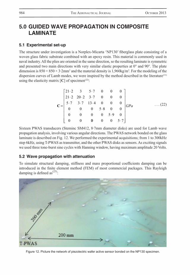
The structure under investigation is a Norplex-Micarta ‘NP130’ fiberglass plate consisting of a woven glass fabric substrate combined with an epoxy resin. This material is commonly used in naval industry. All the plies are oriented in the same direction, so the resulting laminate is symmetric and presented two main directions with very similar elastic properties at 0° and 90°. The plate dimension is 850 × 850 × 3·2mm3 and the material density is 1,960kg/m3. For the modeling of the dispersion curves of Lamb modes, we were inspired by the method described in the literature(11)
using the elasticity matrix [C] of specimen(22):
. . . (22)
Sixteen PWAS transducers (Steminc SM412, 8·7mm diameter disks) are used for Lamb wave propagation analysis, involving various angular directions. The PWAS network bonded on the glass laminate is described on Fig. 12. We performed the experimental acquisitions; from 1 to 300kHz step 6kHz, using T-PWAS as transmitter, and the other PWAS disks as sensors. As exciting signals we used three tone-burst sine cycles with Hanning window, having maximum amplitude 20 Volts.
5.2 Wave propagation with attenuation
To simulate structural damping, stiffness and mass proportional coefficients damping can be introduced in the finite element method (FEM) of most commercial packages. This Rayleigh damping is defined as(23):
C
21 2 3 5 7 0 0 021 2 20 2 3 7 0 0 05 7 3 7 13 4 0 0 00 0 0 5 8 0 00 0 0 0 5 9 00 0 00 0 0 5 7
GPa
Figure 12. Picture the network of piezolectric wafer active sensor bonded on the NP130 specimen.
Gresil et al Guided wAVe propAGAtion in composite lAminAte mAteriAl usinG piezoelectric... 985
. . . (23)
where αM and βk are the mass and stiffness proportionality coefficients. The mass proportional damping coefficient αM introduces damping forces caused by the absolute velocities of the model and so simulates the idea of the model moving through a viscous ‘medium’. The stiffness propor-tional damping coefficient βk introduces damping proportional to the strain rate, which can be thought of as damping associated with the material itself. With the application of this principle, the coupled-field FEM matrix element can be expressed as follows(24,25):
. . . (24)
where [M], [C] and [K] are the structural mass, damping, and stiffness matrices, respectively; {u} and {v} are the vectors of nodal displacement and electric potential, respectively, with the dot above variables denoting time derivative; {F} is the force vector, {L} is the vector of nodal, surface and body charges, {Kz} is the piezoelectric coupling matrix, and [Kd] is the dielectric conductivity.We can also write in terms of the damping ratio, ζ:
. . . (25)
Where Cc is the coefficient of critical damping and ω is the circular frequency ω = 2πf and f is the frequency. The logarithmic decrement(23) is expressed as follows:
. . . (26)
Where u is amplitude and un is the amplitude of vibration after n cycles. Since ζ is a very small number, its square is much less than unity. So the denominator in Equation (26) is assumed to be unity. Equation (26) then becomes:
. . . (27)
When the frequency is very high (above 5MHz), vibration, which is global phenomenon, becomes a local phenomenon(26), which represents no damping effect on the wave propagation. In our case, specifically on guided wave in composite laminate, with the frequency range 50kHz to 500kHz, the Rayleigh damping play a fundamental role on Lamb wave propagation.
The amplitude of Lamb modes are A1 and A2 and the time of flight (ToF), of Lamb mode are t1 and t2 at arbitrary reference positions, x1 and x2, respectively. If Cg is the group velocity of the mode (S, A, and SH modes), then the following expression represents the ToF, Cg and distance of travel:
. . . (28)
M u
VC
00 0
00 0
uu
V
K K
K K
uV
Z
Z T d
FL
C M KM K
ccc
12
ln uu
n
n
21 2
r uu
nvn
ln 2
t t t x xC
xCg g
2 12 1
986 the AeronAuticAl JournAl october 2013
If kI(ω) is the attenuation coefficient of the viscoelastic medium, the following equation can be written for obtaining the amplitude ratio(8,28):
. . . (29)
. . . (30)
Assuming that the locations of reference positions were chosen in such a way that ∆t can be expressed as the product of the number of cycles (n) and wave period (T = 1/f), and substituting the same in Equation (30), we have: . . . (31)
From equation , by substituting the value of n in equation , we have:
. . . (32)
Then we have: . . . (33)
The parameter kI(ω) is called attenuation in neper (Np) par length. The unit neper is dimensionless; it specifies the base of the decay to be e (compared to the unit decibel (dB) which specifies the base of the decay to be 10 (1Np = 20log10e = 8·868db). To implement proportional damping in numerical modeling, αM and βK values have to be known.
Assume that stiffness proportional damping for the Lamb wave is zero. Then Equation will be: . . . (34)
Substituting Equation in Equation , we obtain: . . . (35)
Equation gives the value of mass proportional damping. For a given composite laminate, kI(ω) has to be determined experimentally and Cg is theoretical calculated.
Now, to estimate the stiffness proportional damping βK, we assumed that the mass proportional damping is zero. Then Equation will be:
. . . (36)
Substituting Equation (36) in Equation (33), we obtain: . . . (37)
AA
e k xI1
2
( )
r AA
k w xI
ln ( )1
2
t nT nf
xCg
r f xCvg
2
k fC CIg g
( ) 2
M
2
M g IC k 2 ( )
K
2
Kg IC k
2
2
( )
Gresil et al Guided wAVe propAGAtion in composite lAminAte mAteriAl usinG piezoelectric... 987
Equation (37) gives the value of stiffness proportional damping. The relation between αM and βK can be written as(28):
. . . (38)
6.0 RESULTS AND DISCUSSIONS
6.1 Dispersion curve in composite laminate
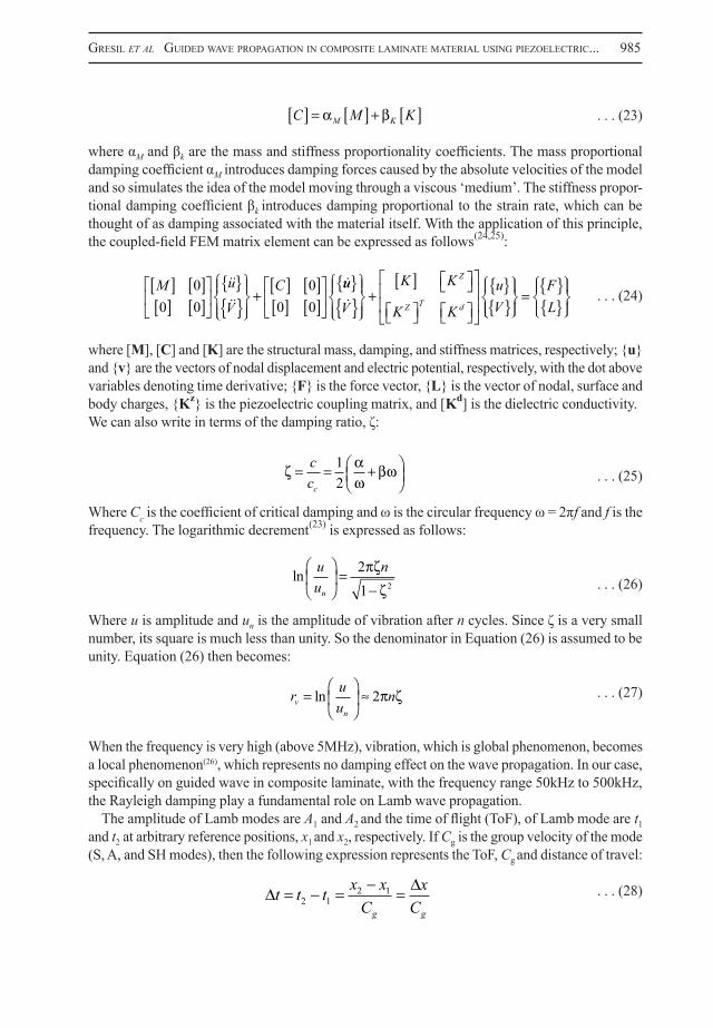
A computer code was developed to predict the wave propagation in a laminate composite using the analysis method presented in papers(9). Figures 13(a) and 13(b) show the dispersions curves obtained in the field f × d <1·6MHz.mm and Cp < 5km/s (anti-symmetric mode (A) in blue, symmetrical mode (S) in red, and shear horizontal mode (SH) in green).
The practical frequency ranges from the very low frequencies, where only the three fundamental modes can propagate in the structure, up to approximately 280kHz. Beyond this point, single mode excitation becomes more difficult due to numerous modes that the structure supports at higher frequencies.
M
K
2
Figure 13. Theoretical dispersion curves of the glass laminate.
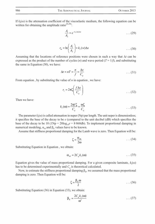
Figure 14. Comparison between experimental and analytical dispersion curves for the propagation path at 0°.
988 the AeronAuticAl JournAl october 2013
Figure 14 shows the experimental dispersion curve for the propagation path at 0°. As we can observe, only two modes are present, A0 and S0 mode. Moreover the velocities of these modes have an acceptable match with the theoretical dispersion curve. The SH0 mode is not present because the PWAS has no capability to excite and to catch this shear mode.
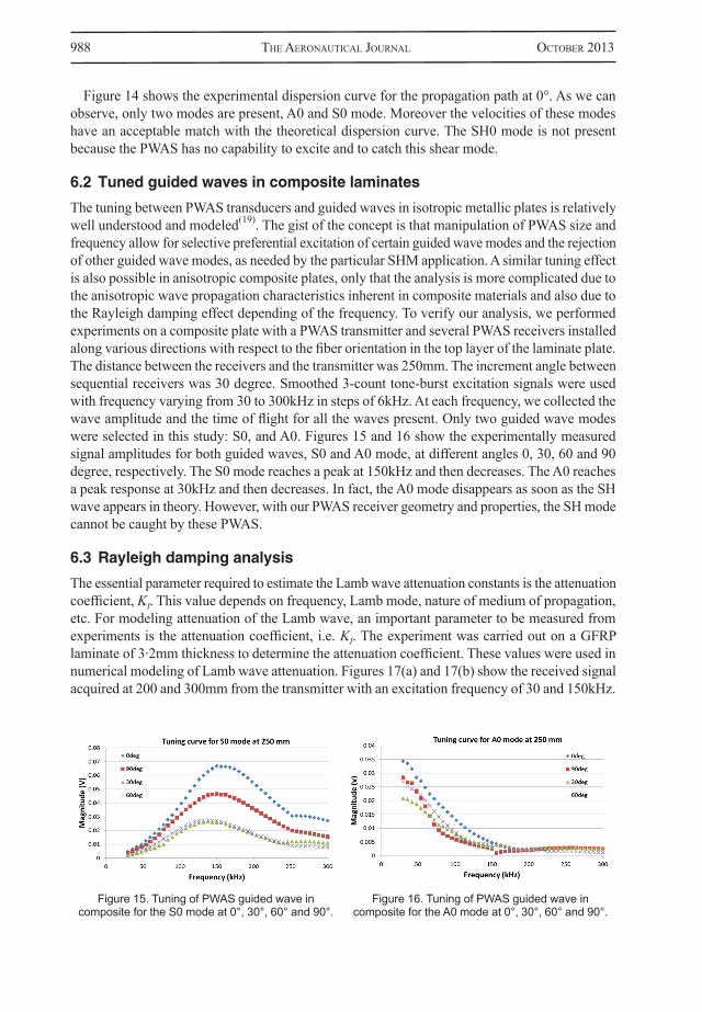
6.2 Tuned guided waves in composite laminates
The tuning between PWAS transducers and guided waves in isotropic metallic plates is relatively well understood and modeled(19). The gist of the concept is that manipulation of PWAS size and frequency allow for selective preferential excitation of certain guided wave modes and the rejection of other guided wave modes, as needed by the particular SHM application. A similar tuning effect is also possible in anisotropic composite plates, only that the analysis is more complicated due to the anisotropic wave propagation characteristics inherent in composite materials and also due to the Rayleigh damping effect depending of the frequency. To verify our analysis, we performed experiments on a composite plate with a PWAS transmitter and several PWAS receivers installed along various directions with respect to the fiber orientation in the top layer of the laminate plate. The distance between the receivers and the transmitter was 250mm. The increment angle between sequential receivers was 30 degree. Smoothed 3-count tone-burst excitation signals were used with frequency varying from 30 to 300kHz in steps of 6kHz. At each frequency, we collected the wave amplitude and the time of flight for all the waves present. Only two guided wave modes were selected in this study: S0, and A0. Figures 15 and 16 show the experimentally measured signal amplitudes for both guided waves, S0 and A0 mode, at different angles 0, 30, 60 and 90 degree, respectively. The S0 mode reaches a peak at 150kHz and then decreases. The A0 reaches a peak response at 30kHz and then decreases. In fact, the A0 mode disappears as soon as the SH wave appears in theory. However, with our PWAS receiver geometry and properties, the SH mode cannot be caught by these PWAS.
6.3 Rayleigh damping analysis
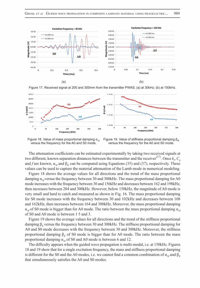
The essential parameter required to estimate the Lamb wave attenuation constants is the attenuation coefficient, KI. This value depends on frequency, Lamb mode, nature of medium of propagation, etc. For modeling attenuation of the Lamb wave, an important parameter to be measured from experiments is the attenuation coefficient, i.e. KI. The experiment was carried out on a GFRP laminate of 3·2mm thickness to determine the attenuation coefficient. These values were used in numerical modeling of Lamb wave attenuation. Figures 17(a) and 17(b) show the received signal acquired at 200 and 300mm from the transmitter with an excitation frequency of 30 and 150kHz.
Figure 15. Tuning of PWAS guided wave in composite for the S0 mode at 0°, 30°, 60° and 90°.
Figure 16. Tuning of PWAS guided wave in composite for the A0 mode at 0°, 30°, 60° and 90°.
Gresil et al Guided wAVe propAGAtion in composite lAminAte mAteriAl usinG piezoelectric... 989
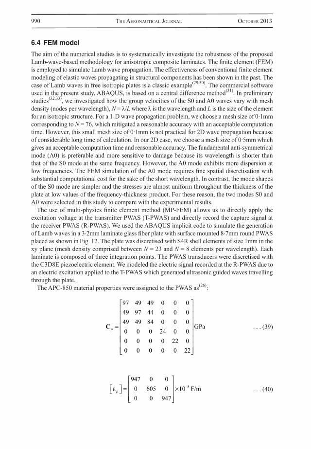
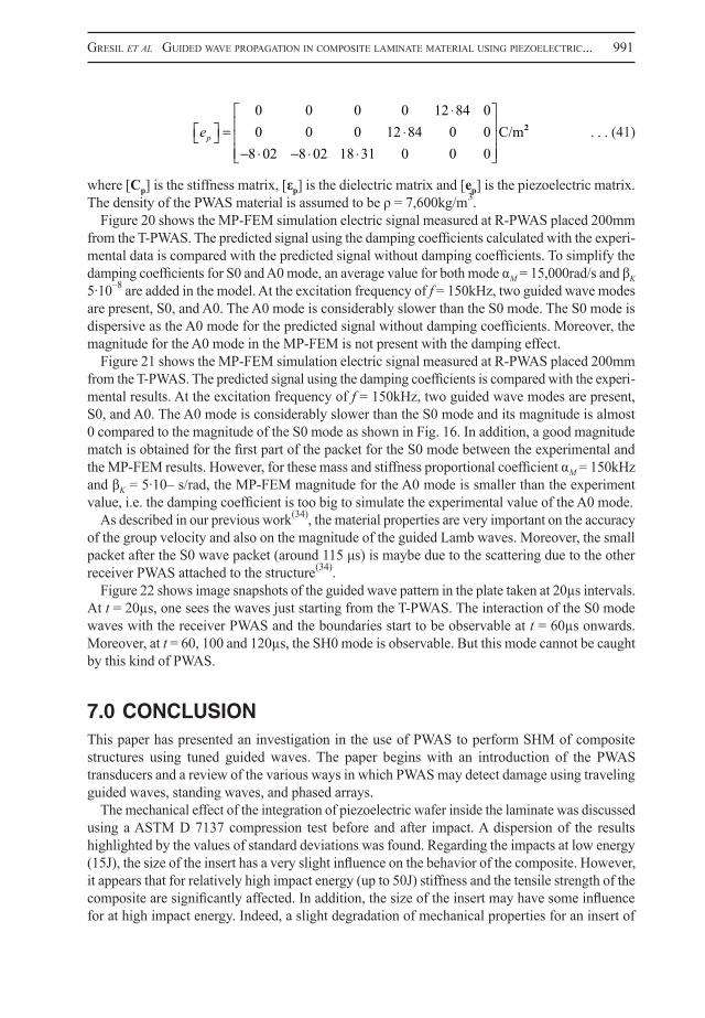
The attenuation coefficients can be estimated experimentally by taking two received signals at two different, known separation distances between the transmitter and the receiver(27). Once kI, Cg and f are known, αM and βK can be computed using Equations (35) and (37), respectively. These values can be used to capture the material attenuation of the Lamb mode in numerical modeling.
Figure 18 shows the average values for all directions and the trend of the mass proportional damping αM versus the frequency between 30 and 300kHz. The mass proportional damping for A0 mode increases with the frequency between 30 and 156kHz and decreases between 162 and 198kHz, then increases between 204 and 300kHz. However, below 150kHz, the magnitude of A0 mode is very small and hard to catch and measured as shown in Fig. 16. The mass proportional damping for S0 mode increases with the frequency between 30 and 102kHz and decreases between 108 and 162kHz, then increases between 164 and 300kHz. Moreover, the mass proportional damping αM of S0 mode is bigger than for A0 mode. The ratio between the mass proportional damping αM of S0 and A0 mode is between 1·5 and 3.
Figure 19 shows the average values for all directions and the trend of the stiffness proportional damping βK versus the frequency between 30 and 300kHz. The stiffness proportional damping for A0 and S0 mode decreases with the frequency between 30 and 300kHz. Moreover, the stiffness proportional damping βK of S0 mode is bigger than for A0 mode. The ratio between the mass proportional damping αM of S0 and A0 mode is between 6 and 12.
The difficulty appears when the guided wave propagation is multi-modal, i.e. at 150kHz. Figures 18 and 19 show that for a single excitation frequency, the mass and stiffness proportional damping is different for the S0 and the A0 modes, i.e. we cannot find a common combination of αM and βK that simultaneously satisfies the A0 and S0 modes.
Figure 17. Received signal at 200 and 300mm from the transmitter PWAS; (a) at 30kHz; (b) at 150kHz.
Figure 18. Value of mass proportional damping αM versus the frequency for the A0 and S0 mode.
Figure 19. Value of stiffness proportional damping βK versus the frequency for the A0 and S0 mode.
(a) (b)
990 the AeronAuticAl JournAl october 2013
6.4 FEM model
The aim of the numerical studies is to systematically investigate the robustness of the proposed Lamb-wave-based methodology for anisotropic composite laminates. The finite element (FEM) is employed to simulate Lamb wave propagation. The effectiveness of conventional finite element modeling of elastic waves propagating in structural components has been shown in the past. The case of Lamb waves in free isotropic plates is a classic example(29,30). The commercial software used in the present study, ABAQUS, is based on a central difference method(31). In preliminary studies(32,33), we investigated how the group velocities of the S0 and A0 waves vary with mesh density (nodes per wavelength), N = λ/L where λ is the wavelength and L is the size of the element for an isotropic structure. For a 1-D wave propagation problem, we choose a mesh size of 0·1mm corresponding to N = 76, which mitigated a reasonable accuracy with an acceptable computation time. However, this small mesh size of 0·1mm is not practical for 2D wave propagation because of considerable long time of calculation. In our 2D case, we choose a mesh size of 0·5mm which gives an acceptable computation time and reasonable accuracy. The fundamental anti-symmetrical mode (A0) is preferable and more sensitive to damage because its wavelength is shorter than that of the S0 mode at the same frequency. However, the A0 mode exhibits more dispersion at low frequencies. The FEM simulation of the A0 mode requires fine spatial discretisation with substantial computational cost for the sake of the short wavelength. In contrast, the mode shapes of the S0 mode are simpler and the stresses are almost uniform throughout the thickness of the plate at low values of the frequency-thickness product. For these reason, the two modes S0 and A0 were selected in this study to compare with the experimental results.
The use of multi-physics finite element method (MP-FEM) allows us to directly apply the excitation voltage at the transmitter PWAS (T-PWAS) and directly record the capture signal at the receiver PWAS (R-PWAS). We used the ABAQUS implicit code to simulate the generation of Lamb waves in a 3·2mm laminate glass fiber plate with surface mounted 8·7mm round PWAS placed as shown in Fig. 12. The plate was discretised with S4R shell elements of size 1mm in the xy plane (mesh density comprised between N = 23 and N = 8 elements per wavelength). Each laminate is composed of three integration points. The PWAS transducers were discretised with the C3D8E piezoelectric element. We modeled the electric signal recorded at the R-PWAS due to an electric excitation applied to the T-PWAS which generated ultrasonic guided waves travelling through the plate.
The APC-850 material properties were assigned to the PWAS as(26):
. . . (39)
. . . (40)
C p
97 49 49 0 0 049 97 44 0 0 049 49 84 0 0 00 0 0 24 0 00 0 0 0 22 00 0 0 0 0 22
GPa
p
947 0 00 605 00 0 947
10 8 F/m
Gresil et al Guided wAVe propAGAtion in composite lAminAte mAteriAl usinG piezoelectric... 991
. . . (41)
where [Cp] is the stiffness matrix, [εp] is the dielectric matrix and [ep] is the piezoelectric matrix. The density of the PWAS material is assumed to be ρ = 7,600kg/m3.
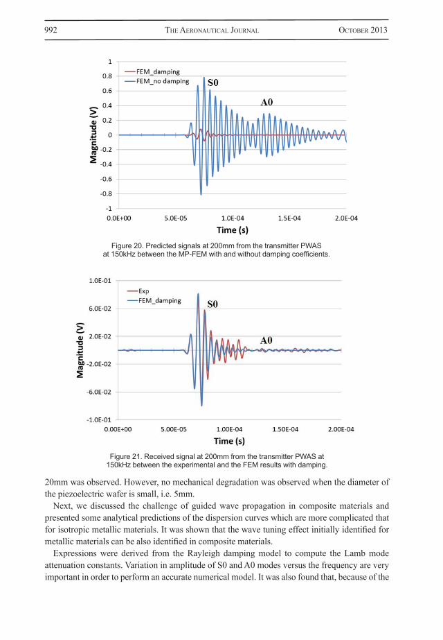
Figure 20 shows the MP-FEM simulation electric signal measured at R-PWAS placed 200mm from the T-PWAS. The predicted signal using the damping coefficients calculated with the experi-mental data is compared with the predicted signal without damping coefficients. To simplify the damping coefficients for S0 and A0 mode, an average value for both mode αM = 15,000rad/s and βK 5·10–8 are added in the model. At the excitation frequency of f = 150kHz, two guided wave modes are present, S0, and A0. The A0 mode is considerably slower than the S0 mode. The S0 mode is dispersive as the A0 mode for the predicted signal without damping coefficients. Moreover, the magnitude for the A0 mode in the MP-FEM is not present with the damping effect.
Figure 21 shows the MP-FEM simulation electric signal measured at R-PWAS placed 200mm from the T-PWAS. The predicted signal using the damping coefficients is compared with the experi-mental results. At the excitation frequency of f = 150kHz, two guided wave modes are present, S0, and A0. The A0 mode is considerably slower than the S0 mode and its magnitude is almost 0 compared to the magnitude of the S0 mode as shown in Fig. 16. In addition, a good magnitude match is obtained for the first part of the packet for the S0 mode between the experimental and the MP-FEM results. However, for these mass and stiffness proportional coefficient αM = 150kHz and βK = 5·10– s/rad, the MP-FEM magnitude for the A0 mode is smaller than the experiment value, i.e. the damping coefficient is too big to simulate the experimental value of the A0 mode.
As described in our previous work(34), the material properties are very important on the accuracy of the group velocity and also on the magnitude of the guided Lamb waves. Moreover, the small packet after the S0 wave packet (around 115 μs) is maybe due to the scattering due to the other receiver PWAS attached to the structure(34).
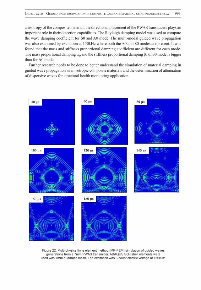
Figure 22 shows image snapshots of the guided wave pattern in the plate taken at 20µs intervals. At t = 20µs, one sees the waves just starting from the T-PWAS. The interaction of the S0 mode waves with the receiver PWAS and the boundaries start to be observable at t = 60µs onwards. Moreover, at t = 60, 100 and 120µs, the SH0 mode is observable. But this mode cannot be caught by this kind of PWAS.
7.0 CONCLUSIONThis paper has presented an investigation in the use of PWAS to perform SHM of composite structures using tuned guided waves. The paper begins with an introduction of the PWAS transducers and a review of the various ways in which PWAS may detect damage using traveling guided waves, standing waves, and phased arrays.
The mechanical effect of the integration of piezoelectric wafer inside the laminate was discussed using a ASTM D 7137 compression test before and after impact. A dispersion of the results highlighted by the values of standard deviations was found. Regarding the impacts at low energy (15J), the size of the insert has a very slight influence on the behavior of the composite. However, it appears that for relatively high impact energy (up to 50J) stiffness and the tensile strength of the composite are significantly affected. In addition, the size of the insert may have some influence for at high impact energy. Indeed, a slight degradation of mechanical properties for an insert of
ep
0 0 0 0 12 84 00 0 0 12 84 0 08 02 8 02 18 31 0 0 0
C/m22
992 the AeronAuticAl JournAl october 2013
20mm was observed. However, no mechanical degradation was observed when the diameter of the piezoelectric wafer is small, i.e. 5mm.
Next, we discussed the challenge of guided wave propagation in composite materials and presented some analytical predictions of the dispersion curves which are more complicated that for isotropic metallic materials. It was shown that the wave tuning effect initially identified for metallic materials can be also identified in composite materials.
Expressions were derived from the Rayleigh damping model to compute the Lamb mode attenuation constants. Variation in amplitude of S0 and A0 modes versus the frequency are very important in order to perform an accurate numerical model. It was also found that, because of the
Figure 21. Received signal at 200mm from the transmitter PWAS at 150kHz between the experimental and the FEM results with damping.
Figure 20. Predicted signals at 200mm from the transmitter PWAS at 150kHz between the MP-FEM with and without damping coefficients.
Gresil et al Guided wAVe propAGAtion in composite lAminAte mAteriAl usinG piezoelectric... 993
anisotropy of the composite material, the directional placement of the PWAS transducers plays an important role in their detection capabilities. The Rayleigh damping model was used to compute the wave damping coefficient for S0 and A0 mode. The multi-modal guided wave propagation was also examined by excitation at 150kHz where both the A0 and S0 modes are present. It was found that the mass and stiffness proportional damping coefficient are different for each mode. The mass proportional damping αM and the stiffness proportional damping βK of S0 mode is bigger than for A0 mode.
Further research needs to be done to better understand the simulation of material damping in guided wave propagation in anisotropic composite materials and the determination of attenuation of dispersive waves for structural health monitoring application.
Figure 22. Multi-physics finite element method (MP-FEM) simulation of guided waves generations from a 7mm PWAS transmitter. ABAQUS S8R shell elements were
used with 1mm quadratic mesh. The excitation was 3-count electric voltage at 150kHz.
994 the AeronAuticAl JournAl october 2013
REFERENCES1. lAmb, H. On waves in an elastic plate, Proceedings of the Royal Society of London; Philosophical
Transactions of the Royal Society, 1917, pp 114-128. 2. ViktoroV, I.A. Rayleigh and Lamb waves – Physical theory and application, New York Plenum Press,
1967.3. Auld, B.A. Acoustic Fields and Waves in Solids, John Wiley and Sons, New York, USA, 1973.4. AchenbAch, J.D. Lamb waves as thickness vibrations superimposed on a membrane carrier wave, J
Acoust Soc Am, 1998, 5, (103), pp 2283-2286. 5. AchenbAch, J.D. and Xu, Y. Use of elastodynamic reciprocity to analyze point-load generated axisym-
metric waves in plate, Wave Motion, 1999, 30, (1), pp 57-67. 6. hAyAshi, T. and endoh, S. Calculation and visualization of Lamb wave motion, Ultrasonics, 2000, (38),
pp 770-773.7. moreno, e., AceVedo, P. and cAstillo, M. Pulse propagation in plate elements, European journal of
mechanics A/Solids, 2003, (22), pp 283-294. 8. rose, J.L. Ultrasonic Waves in Solid Media, Cambridge University: Cambridge University Press,
Cambridge, UK, 1999.9. nAyfeh, A.N. and chimenti, D.E. Free wave propagation in plates of general anisotropic media, J Applied
Mechanics, 1989, 56, pp 881-886. 10. liAnd, Y. and thomson, R.B. Influence of anisotropy on the dispersion characteristics of guided ultrasonic
plates mode, J Acoust Soc Am, 1990, 87, (5), pp 1911-1931. 11. nAyfeh, A.D. Wave propagation in layered anisotropic media with applications to composite, Amsterdam,
The Netherlands, Elsevier, 1995.12. lowe, M.J.S. Matrix techniques for modeling ultrasonics waves in multilayered media, IEEE Transactions
on Ultrasonics, 1995, 42, (4), pp 525-542. 13. pierce, s.G. culshAw, b. philp, w.r. lecuyer, f. and fArlow, r. Broadband Lamb wave measurements
in aluminum and carbon: glass fibre reinforced composite materials using non contacting laser generation and detection, Ultrasonics, 1997, 58, pp 105-114.
14. liu, T., Veidt, M. and kitipornchAi, S. Single mode Lamb waves in composite laminated plates generated by piezoelectric transducers, Composite Structures, 2002, 58, (3), pp 381-396.
15. Gresil, M. Contribution À L’étude Du Contrôle De Santé Intégré Associé À Une Protection Électroma-gnétique Pour Les Matériaux Composites, PhD dissertation, Department of electronic, Ecole Normale Superieure de Cachan-ENS Cachan, Cachan, 2009.
16. blAnquet, P. Etude De L’endommagement Des Matériaux Composites Aéronautiques À Partir Des Techniques Ultrasonores, PhD dissertation, Université de Valenciennes et du Hainaut Cambrésis, 1997.
17. lin, M. and chAnG, F.K. The manufacture of composite structures with a built-in network of piezoce-ramics, Composites Science and Technology, 2002, 62, (7-8), pp 919-939.
18. shi, Y. and soutis, C. A finite element analysis of impact damage in composites laminates, Aeronaut J, 2012, 116, (1186), pp 1331-1346.
19. GiurGiutiu, V. Structural Health Monitoring With Piezoelectric Wafer Active Sensor, Elsevier Academic Press, Amsterdam, The Netherlands, 2008.
20. dieulesAint, E. and royer, D. Ondes élastiques dans les solides: application au traitement de signal, Masson, 407 pages, 1974.
21. zhAnG, Z.Y. and richArdson, M.O.W. Low velocity impact induced damage evaluation and its effect on the residual flexural properties of pultruded GRP composites, Composite Structures, 2007, 81, pp 195-201.
22. pollock, p., yu, l., sutton, m.A., Guo, s., mAJumdAr, p. and Gresil, m. Full-Field Measurements for Determining Orthotropic Elastic Parameters of Woven Glass-Epoxy Composites Using Off-Axis Tensile Specimens, Experimental Techniques, 2012, doi: 10.1111/j.1747-1567.2012.00824.x
23. meiroVitch, L. Fundamentals of Vibration, McGraw Hill Publications, 2003.24. moVeni, S. Finite Element Analysis, theory application with Ansys, New-Jersey, 2003.25. ANSYS reference manual, 8.1, R, Ed., ed.: Canonsburg, PA: ANSYS, 2004.26. Gresil, M., yu, L., GiurGiutiu, V. and sutton, M. Predictive modeling of electromechanical
impedance spectroscopy for composite materials, Structural Health Monitoring, 2012, 11, (6), pp 671-683.
27. cAstAinGs, M. and hosten, B. The use of electrostatic, ultrasonic, air-coupled transducers to generate and receive Lamb waves in anisotropic, viscoelastic plates, Ultrasonics, 1998, 36, (1), pp 361-365.

Gresil et al Guided wAVe propAGAtion in composite lAminAte mAteriAl usinG piezoelectric... 995
28. rAmAdAs, c., bAlAsubrAmAniAm, k., hood, A., Joshi, m. and krishnAmurthy, c.V. Modelling of attenuation of Lamb waves using Rayleigh damping: Numerical and experimental studies, Composite Structures, 2011, 93, (8), pp 2020-2025.
39. Alleyne, D.N. and cAwley, P. A 2-dimensional Fourier transform method for the quantitative measurement of Lamb modes, IEEE Ultrasonics Symposium, 1990, pp 1143-1146.
30. moser, f. JAcobs, l.J. and qu, J. Modeling elastic wave propagation in waveguides with the finite element method, NDT & E International, 1999, 32, (4), pp 225-234.
31. ABAQUS, Analysis User’s Manual, 6-9.2 ed, 2008.32. Gresil, m., shen, y. and GiurGiutiu, V. Predictive modeling of ultrasonics SHM with PWAS transducers,
8th International Workshop on Structural Health Monitoring, 2011, Stanford, California, USA.33. Gresil, m., shen, y. and GiurGiutiu, V. Benchmark problems for predictive fem simulation of 1-D and
2-D guided waves for structural health monitoring with piezoelectric wafer active sensors, Review of Progress in Quantitative Non-destructive Evaluation, 2011, 1430, (1), pp 1835-1842.
34. Gresil, m. and GiurGiutiu, V. Guided wave propagation in carbon composite laminate using piezoelectric wafer active sensors’, Proc. of SPIE, 2013, 8695, (77).

![Excitation and Propagation of Guided Waves in Multilayer ... · propagation in hollow cylindrical structures. Li et al.[9] modeled the guided wave propagation in a pressure vessel](https://img.pdfslide.us/doc/110x75/60610ee6bd7e2a0a42396346/excitation-and-propagation-of-guided-waves-in-multilayer-propagation-in-hollow.jpg)


![PROPAGATION OF ELECTROMAGNETIC WAVES GUIDED BY THE ... · dielectric-loaded tape helix. D’Agostino et al. [13] and Tsutaki et al. [14] based their analysis of guided electromagnetic](https://img.pdfslide.us/doc/110x75/6026944923f71c3f1a42e447/propagation-of-electromagnetic-waves-guided-by-the-dielectric-loaded-tape-helix.jpg)


![7. PLANE WAVE PROPAGATION - sonoma.edu€¦ · Review We have learned about wave propagation Guided propagation Skywave [f=3- 3- Mhz] Cable Transmission Line Reflected wave Constructive](https://img.pdfslide.us/doc/110x75/5b5e7f967f8b9a164b8c9800/7-plane-wave-propagation-review-we-have-learned-about-wave-propagation-guided.jpg)