Embed Size (px)
Citation preview
Guided drives DFM-N-B, NPT
Subject to change – 2018/052 � Internet: www.festo.com/catalog/...
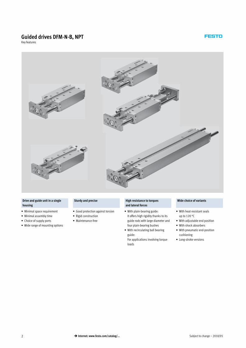
Guided drives DFM-N-B, NPTKey features
Drive and guide unit in a single
housing
Sturdy and precise High resistance to torques
and lateral forces
Wide choice of variants
� Minimal space requirement
� Minimal assembly time
� Choice of supply ports
� Wide range of mounting options
� Good protection against torsion
� Rigid construction
� Maintenance-free
� With plain-bearing guide:
It offers high rigidity thanks to its
guide rods with large diameter and
four plain-bearing bushes
� With recirculating ball bearing
guide:
For applications involving torque
loads
� With heat-resistant seals
up to 120 °C
� With adjustable end position
� With shock absorbers
� With pneumatic end-position
cushioning
� Long-stroke versions
2018/05 – Subject to change 3� Internet: www.festo.com/catalog/...
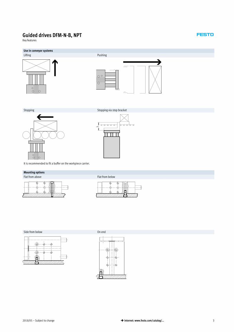
Guided drives DFM-N-B, NPTKey features
Use in conveyor systems
Lifting Pushing
Stopping Stopping via stop bracket
It is recommended to fit a buffer on the workpiece carrier.
Mounting options
Flat from above Flat from below
Side from below On end
Subject to change – 2018/054 � Internet: www.festo.com/catalog/...
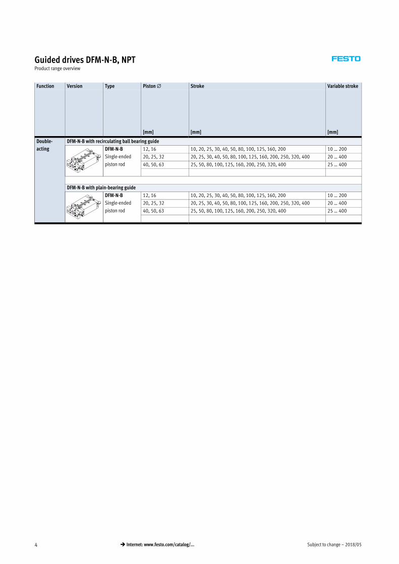
Guided drives DFM-N-B, NPTProduct range overview
Function Version Type Piston � Stroke Variable stroke
[mm] [mm] [mm]
Double-
acting
DFM-N-B with recirculating ball bearing guide
DFM-N-B
Single-ended
piston rod
12, 16 10, 20, 25, 30, 40, 50, 80, 100, 125, 160, 200 10 … 200
20, 25, 32 20, 25, 30, 40, 50, 80, 100, 125, 160, 200, 250, 320, 400 20 … 400
40, 50, 63 25, 50, 80, 100, 125, 160, 200, 250, 320, 400 25 … 400
DFM-N-B with plain-bearing guide
DFM-N-B
Single-ended
piston rod
12, 16 10, 20, 25, 30, 40, 50, 80, 100, 125, 160, 200 10 … 200
20, 25, 32 20, 25, 30, 40, 50, 80, 100, 125, 160, 200, 250, 320, 400 20 … 400
40, 50, 63 25, 50, 80, 100, 125, 160, 200, 250, 320, 400 25 … 400
2018/05 – Subject to change 5� Internet: www.festo.com/catalog/...
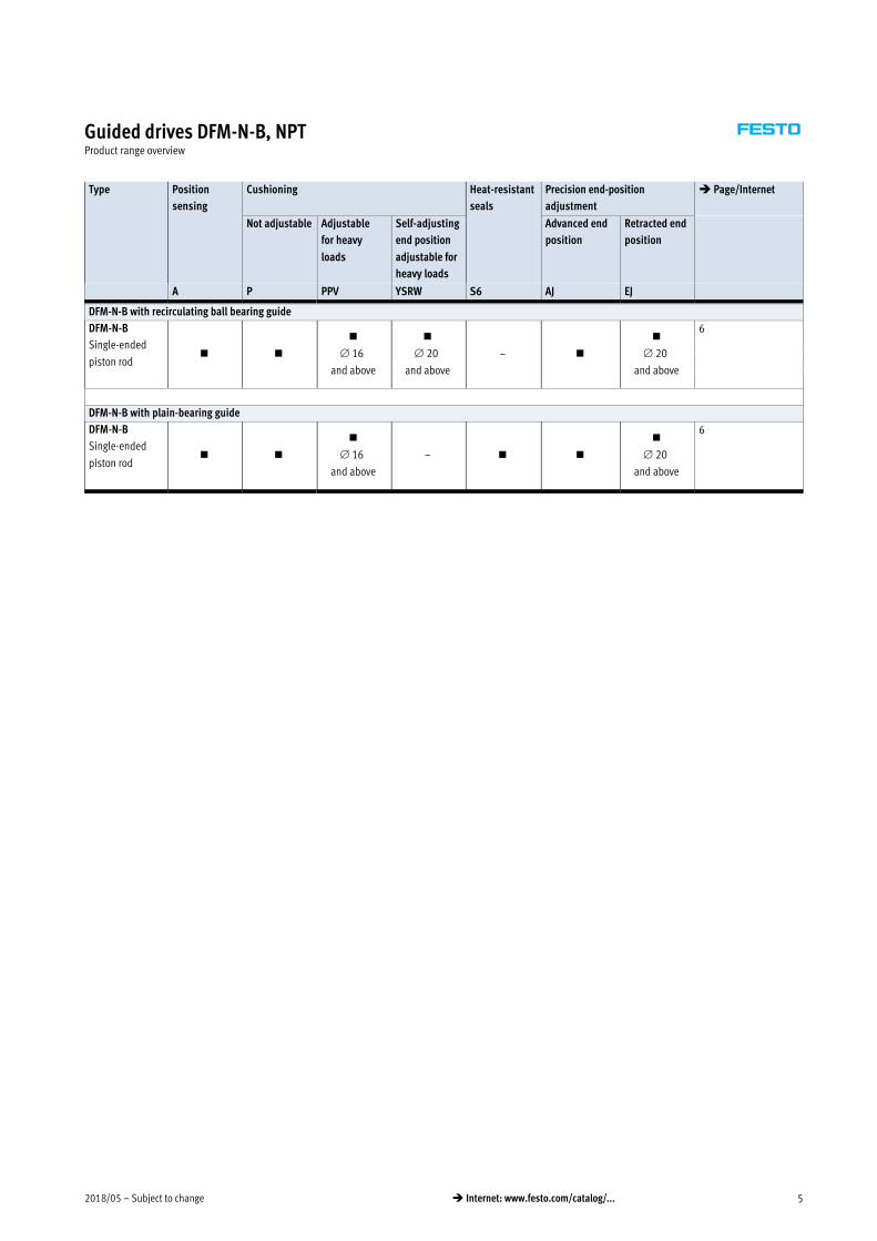
Guided drives DFM-N-B, NPTProduct range overview
Type Position
sensing
Cushioning Heat-resistant
seals
Precision end-position
adjustment
� Page/Internet
Not adjustable Adjustable
for heavy
loads
Self-adjusting
end position
adjustable for
heavy loads
Advanced end
position
Retracted end
position
A P PPV YSRW S6 AJ EJ
DFM-N-B with recirculating ball bearing guide
DFM-N-B
Single-ended
piston rod� �
�
16
and above
�
20
and above
– �
�
20
and above
6
DFM-N-B with plain-bearing guide
DFM-N-B
Single-ended
piston rod� �
�
16
and above
– � �
�
20
and above
6

Subject to change – 2018/056 � Internet: www.festo.com/catalog/...
Guided drives DFM-N-B, NPTPeripherals overview
4
1
2
3
4
1
DFM-N-B-12-P
DFM-N-B-12-P-AJ
Variants
AJ EJ AJ + EJ YSRW
Accessories
Description � Page/Internet
1 Push-in fitting
QS
For connecting compressed air tubing with standard O.D. qs
2 Proximity sensor
SME-/SMT-8
Can be integrated in the profile barrel 41
3 Slot cover
ABP-5-S
For protecting the sensor cable and keeping dirt out of the sensor slots 40
4 One-way flow control valve
GRLA
For speed regulation 42
– Centring sleeves
ZBH
4 or 6 pieces included in the scope of delivery 40
-H- Note
Proximity sensors SM…O-8E cannot
be used with the DFM-N-B.

2018/05 – Subject to change 7� Internet: www.festo.com/catalog/...
Guided drives DFM-N-B, NPTType codes
DFM — N — 50 — 80 — B — P — A — GF — S6 — AJ – ZUB — 10S — G
Type
DFM Guided drive
System of units
N Imperial
Piston � [mm]
Stroke [mm]
Generation
B Series
Cushioning
P Flexible cushioning rings/
pads at both ends
PPV Pneumatic cushioning,
adjustable at both ends
YSRW Self-adjusting at both ends
Position sensing
A Via proximity sensor
Guide
GF Plain-bearing guide
KF Recirculating ball bearing
guide
Variant
S6 Heat-resistant seals
up to max. 120 °C
Precision adjustment
AJ Advanced end position
EJ Retracted end position
Accessories
ZUB Supplied separately
Slot cover
…S Sensor slot
Proximity sensor
…G With cable, 2.5 m
…I Contactless with cable, 2.5 m

Subject to change – 2018/058 � Internet: www.festo.com/catalog/...
Guided drives DFM-N-B, NPTTechnical data
Function
-N- Diameter
12 … 63 mm
-T- Stroke length
10 … 400 mm
-W- www.festo.com
DFM-N-B-…-PPVDFM-N-B-…-P
DFM-N-B-…-AJ-EJ DFM-N-B-…-YSRW
General technical data
Piston 12 16 20 25 32 40 50 63
Pneumatic connection M5 suitable for 10-32 UNF 1/8NPT 1/4 NPT
Design Piston
Piston rod
Guide rods with yoke
Cushioning
DFM-…-P Flexible cushioning rings/pads at both ends
DFM-…-PPV – Pneumatic cushioning, adjustable at both ends
DFM-…-YSRW – – Self-adjusting at both ends
Cushioning length
DFM-… -PPV [mm] – 12 15 15 16 17 19 19
Position sensing Via proximity sensor
Type of mounting Via through-holes
Via female thread
Mounting position Any
Protection against torsion/guide Guide rod with yoke/plain-bearing or recirculating ball bearing guide
Variant AJ, EJ and YSRW
Setting range [mm] 0 … 10
Variant EJ and YSRW
Setting range [mm] – – 0 … 10
Variant YSRW with shock absorber
Repetition accuracy [mm] – – Max. 0.05
-H- Note: This product conforms to ISO 1179-1 and to ISO 228-1
2018/05 – Subject to change 9� Internet: www.festo.com/catalog/...
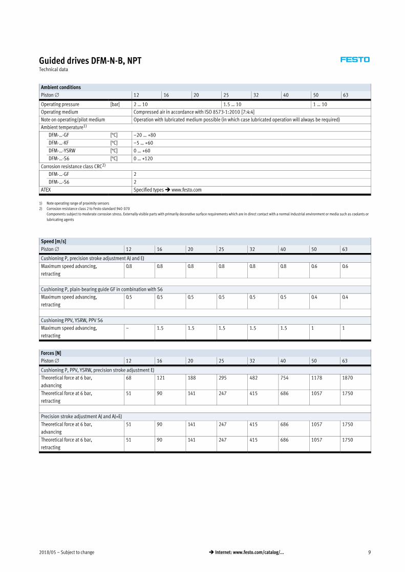
Guided drives DFM-N-B, NPTTechnical data
Ambient conditions
Piston 12 16 20 25 32 40 50 63
Operating pressure [bar] 2 … 10 1.5 … 10 1 … 10
Operating medium Compressed air in accordance with ISO 85731:2010 [7:4:4]
Note on operating/pilot medium Operation with lubricated medium possible (in which case lubricated operation will always be required)
Ambient temperature1)
DFM-…-GF [°C] –20 … +80
DFM-…-KF [°C] –5 … +60
DFM-…-YSRW [°C] 0 … +60
DFM-…-S6 [°C] 0 … +120
Corrosion resistance class CRC2)
DFM-…-GF 2
DFM-…-S6 2
ATEX Specified types � www.festo.com
1) Note operating range of proximity sensors
2) Corrosion resistance class 2 to Festo standard 940 070
Components subject to moderate corrosion stress. Externally visible parts with primarily decorative surface requirements which are in direct contact with a normal industrial environment or media such as coolants or
lubricating agents
Speed [m/s]
Piston 12 16 20 25 32 40 50 63
Cushioning P, precision stroke adjustment AJ and EJ
Maximum speed advancing,
retracting
0.8 0.8 0.8 0.8 0.8 0.8 0.6 0.6
Cushioning P, plain-bearing guide GF in combination with S6
Maximum speed advancing,
retracting
0.5 0.5 0.5 0.5 0.5 0.5 0.4 0.4
Cushioning PPV, YSRW, PPV S6
Maximum speed advancing,
retracting
– 1.5 1.5 1.5 1.5 1.5 1 1
Forces [N]
Piston 12 16 20 25 32 40 50 63
Cushioning P, PPV, YSRW, precision stroke adjustment EJ
Theoretical force at 6 bar,
advancing
68 121 188 295 482 754 1178 1870
Theoretical force at 6 bar,
retracting
51 90 141 247 415 686 1057 1750
Precision stroke adjustment AJ and AJ+EJ
Theoretical force at 6 bar,
advancing
51 90 141 247 415 686 1057 1750
Theoretical force at 6 bar,
retracting
51 90 141 247 415 686 1057 1750

Subject to change – 2018/0510 � Internet: www.festo.com/catalog/...
Guided drives DFM-N-B, NPTTechnical data
Impact energy [J]
Piston 12 16 20 25 32 40 50 63
Cushioning P
Max. impact energy
in the end positions
0.09 0.15 0.2 0.35 0.40 0.7 1.0 1.3
Max. impact energy
in the end positions
S6 0.035 0.075 0.1 0.15 0.2 0.35 0.5 0.65
Cushioning YSRW
Max. energy absorption
per stroke
– – 4 8 12 35 35 70
Max. energy absorption
per hour
– – 21000 30000 41000 68000 68000 100000
vperm.� �2�x�Eperm.
mdead� �� mload
�
mload� �2�x�Eperm.
v2���mdeadMaximum permissible load:
Permissible impact velocity:vperm. Permissible impact velocity
Eperm. Max. impact energy
mIntrinsic Moving load (drive)
mLoad Moving effective load
-H- Note
This data represents the maximum
values that can be achieved. The
maximum permissible impact energy
must be observed.
2018/05 – Subject to change 11� Internet: www.festo.com/catalog/...
Guided drives DFM-N-B, NPTTechnical data
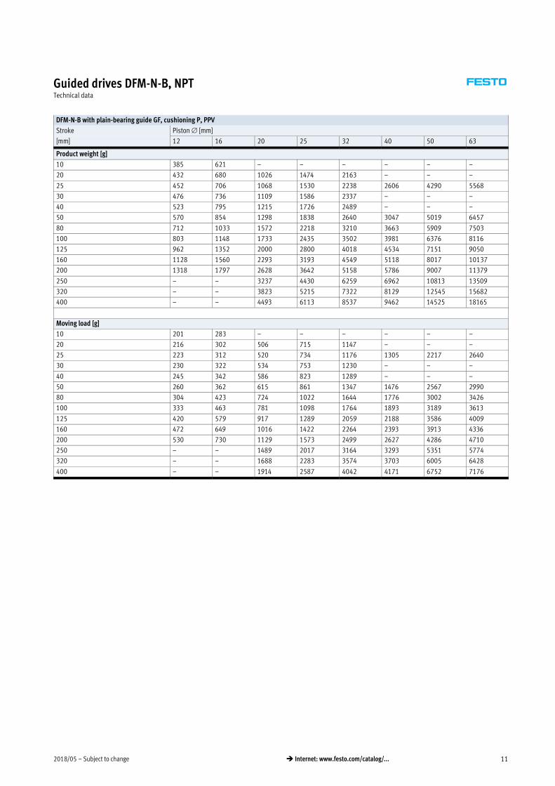
DFM-N-B with plain-bearing guide GF, cushioning P, PPV
Stroke Piston [mm]
[mm] 12 16 20 25 32 40 50 63
Product weight [g]
10 385 621 – – – – – –
20 432 680 1026 1474 2163 – – –
25 452 706 1068 1530 2238 2606 4290 5568
30 476 736 1109 1586 2337 – – –
40 523 795 1215 1726 2489 – – –
50 570 854 1298 1838 2640 3047 5019 6457
80 712 1033 1572 2218 3210 3663 5909 7503
100 803 1148 1733 2435 3502 3981 6376 8116
125 962 1352 2000 2800 4018 4534 7151 9050
160 1128 1560 2293 3193 4549 5118 8017 10137
200 1318 1797 2628 3642 5158 5786 9007 11379
250 – – 3237 4430 6259 6962 10813 13509
320 – – 3823 5215 7322 8129 12545 15682
400 – – 4493 6113 8537 9462 14525 18165
Moving load [g]
10 201 283 – – – – – –
20 216 302 506 715 1147 – – –
25 223 312 520 734 1176 1305 2217 2640
30 230 322 534 753 1230 – – –
40 245 342 586 823 1289 – – –
50 260 362 615 861 1347 1476 2567 2990
80 304 423 724 1022 1644 1776 3002 3426
100 333 463 781 1098 1764 1893 3189 3613
125 420 579 917 1289 2059 2188 3586 4009
160 472 649 1016 1422 2264 2393 3913 4336
200 530 730 1129 1573 2499 2627 4286 4710
250 – – 1489 2017 3164 3293 5351 5774
320 – – 1688 2283 3574 3703 6005 6428
400 – – 1914 2587 4042 4171 6752 7176
Subject to change – 2018/0512 � Internet: www.festo.com/catalog/...
Guided drives DFM-N-B, NPTTechnical data
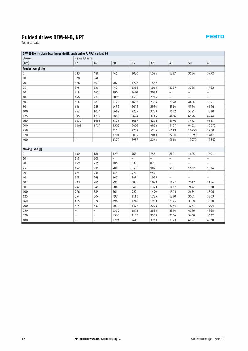
DFM-N-B with plain-bearing guide GF, cushioning P, PPV, variant S6
Stroke Piston [mm]
[mm] 12 16 20 25 32 40 50 63
Product weight [g]
0 283 488 745 1080 1594 1847 3124 3992
10 328 548 – – – – – –
20 376 607 907 1298 1889 – – –
25 395 633 949 1354 1964 2257 3735 4762
30 419 663 990 1410 2063 – – –
40 466 722 1096 1550 2215 – – –
50 514 781 1179 1662 2366 2698 4464 5651
80 656 959 1452 2042 2936 3314 5354 6696
100 747 1074 1614 2259 3228 3632 5821 7310
125 905 1279 1880 2624 3745 4186 6596 8244
160 1072 1486 2173 3017 4276 4770 7462 9331
200 1261 1724 2508 3466 4884 5437 8452 10573
250 – – 3118 4254 5985 6613 10258 12703
320 – – 3704 5039 7048 7780 11990 14876
400 – – 4374 5937 8264 9114 19970 17359
Moving load [g]
0 130 188 329 463 755 810 1428 1601
10 145 208 – – – – – –
20 159 229 386 539 873 – – –
25 167 239 400 558 902 956 1662 1834
30 174 249 414 577 956 – – –
40 188 269 467 647 1015 – – –
50 203 289 495 685 1073 1127 2012 2184
80 247 349 604 847 1373 1427 2447 2620
100 276 389 661 922 1490 1544 2634 2806
125 364 506 797 1113 1785 1840 3031 3203
160 415 576 896 1246 1990 2045 3358 3530
200 474 657 1010 1397 2225 2279 3731 3904
250 – – 1370 1842 2890 2944 4796 4968
320 – – 1568 2107 3300 3354 5450 5622
400 – – 1794 2411 3768 3823 6197 6370
2018/05 – Subject to change 13� Internet: www.festo.com/catalog/...
Guided drives DFM-N-B, NPTTechnical data
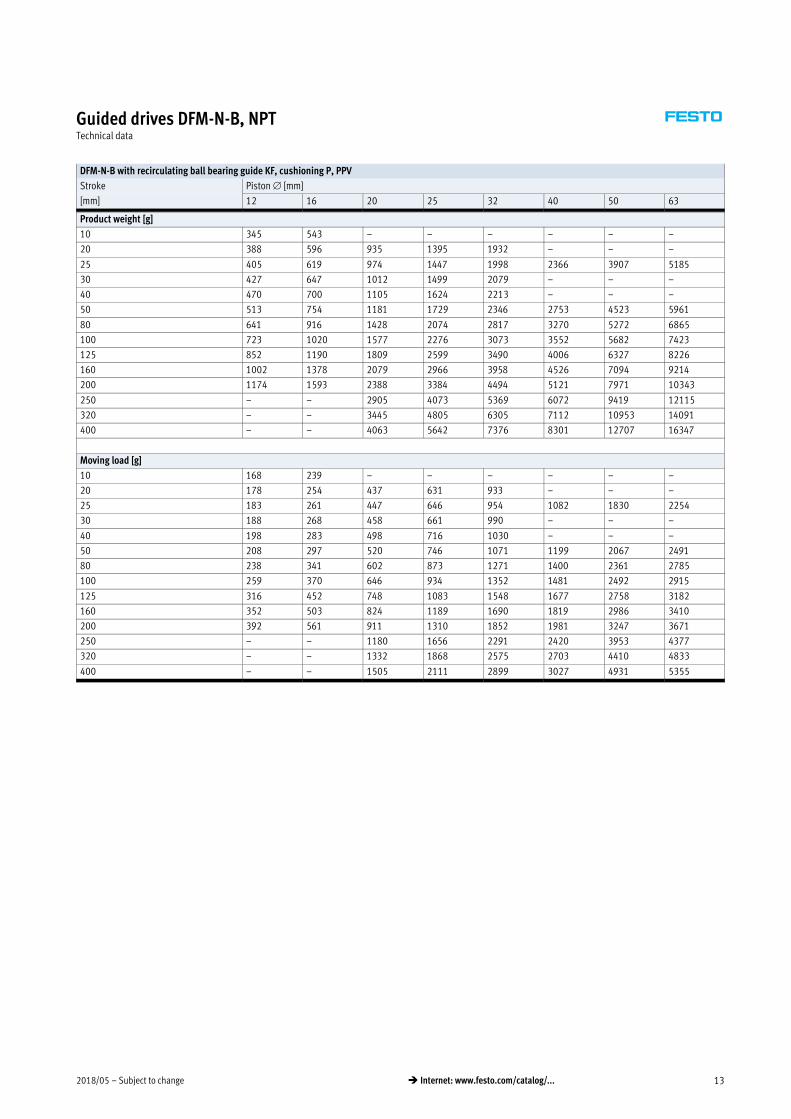
DFM-N-B with recirculating ball bearing guide KF, cushioning P, PPV
Stroke Piston [mm]
[mm] 12 16 20 25 32 40 50 63
Product weight [g]
10 345 543 – – – – – –
20 388 596 935 1395 1932 – – –
25 405 619 974 1447 1998 2366 3907 5185
30 427 647 1012 1499 2079 – – –
40 470 700 1105 1624 2213 – – –
50 513 754 1181 1729 2346 2753 4523 5961
80 641 916 1428 2074 2817 3270 5272 6865
100 723 1020 1577 2276 3073 3552 5682 7423
125 852 1190 1809 2599 3490 4006 6327 8226
160 1002 1378 2079 2966 3958 4526 7094 9214
200 1174 1593 2388 3384 4494 5121 7971 10343
250 – – 2905 4073 5369 6072 9419 12115
320 – – 3445 4805 6305 7112 10953 14091
400 – – 4063 5642 7376 8301 12707 16347
Moving load [g]
10 168 239 – – – – – –
20 178 254 437 631 933 – – –
25 183 261 447 646 954 1082 1830 2254
30 188 268 458 661 990 – – –
40 198 283 498 716 1030 – – –
50 208 297 520 746 1071 1199 2067 2491
80 238 341 602 873 1271 1400 2361 2785
100 259 370 646 934 1352 1481 2492 2915
125 316 452 748 1083 1548 1677 2758 3182
160 352 503 824 1189 1690 1819 2986 3410
200 392 561 911 1310 1852 1981 3247 3671
250 – – 1180 1656 2291 2420 3953 4377
320 – – 1332 1868 2575 2703 4410 4833
400 – – 1505 2111 2899 3027 4931 5355
Subject to change – 2018/0514 � Internet: www.festo.com/catalog/...
Guided drives DFM-N-B, NPTTechnical data
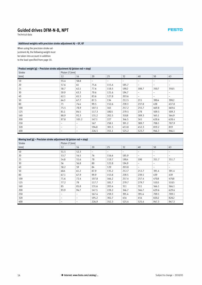
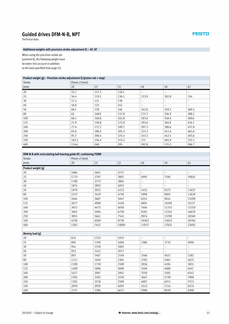
Additional weights with precision stroke adjustment AJ – GF, KF
When using the precision stroke ad
justment AJ, the following weight must
be taken into account in addition
to the load specified from page 10.
Product weight [g] – Precision stroke adjustment AJ (piston rod + stop)
Stroke Piston [mm]
[mm] 12 16 20 25 32 40 50 63
10 55.4 58.8 – – – – – –
20 57.6 61 75.6 115.4 185.7 – – –
25 58.7 62.1 77.6 118.5 190.2 188.7 350.7 350.5
30 59.9 63.3 79.6 121.6 194.7 – – –
40 62.1 65.5 83.6 127.8 203.6 – – –
50 64.3 67.7 87.5 134 212.5 211 390.4 390.2
80 71 74.4 99.5 152.6 239.3 237.8 438 437.8
100 75.5 78.9 107.5 165 257.2 255.7 469.8 469.6
125 81.1 84.5 117.3 180.5 279.5 278 509.5 509.3
160 88.9 92.3 131.2 202.5 310.8 309.3 565.1 564.9
200 97.8 101.2 147.1 227 346.5 345 628.6 628.4
250 – – 167 258.1 391.2 389.7 708.1 707.9
320 – – 194.8 301.5 453.8 452.3 819.2 819
400 – – 226.5 351.1 525.2 523.7 946.3 946.1
Moving load [g] – Precision stroke adjustment AJ (piston rod + stop)
Stroke Piston [mm]
[mm] 12 16 20 25 32 40 50 63
10 51.5 52.3 – – – – – –
20 53.7 54.5 76 116.6 185.9 – – –
25 54.8 55.6 78 119.7 190.4 190 351.7 351.7
30 56 56.8 80 122.8 194.9 – – –
40 58.2 59 84 129 203.8 – – –
50 60.4 61.2 87.9 135.2 212.7 212.7 391.4 391.4
80 67.1 67.9 99.9 153.8 239.5 239.5 439 439
100 71.6 72.4 107.8 166.2 257.4 257.4 470.8 470.8
125 77.2 78 117.7 181.7 279.7 279.7 510.5 510.5
160 85 85.8 131.6 203.4 311 311 566.1 566.1
200 93.9 94.7 147.5 228.2 346.7 346.7 629.6 629.6
250 – – 167.4 259.3 391.4 391.4 709.1 709.1
320 – – 195.2 302.7 454 454 820.2 820.2
400 – – 226.9 352.3 525.4 525.4 947.3 947.3
2018/05 – Subject to change 15� Internet: www.festo.com/catalog/...
Guided drives DFM-N-B, NPTTechnical data
Additional weights with precision stroke adjustment EJ – GF, KF
When using the precision stroke ad
justment EJ, the following weight must
be taken into account in addition
to the load specified from page 10.
Product weight [g] – Precision stroke adjustment EJ (piston rod + stop)
Stroke Piston [mm]
[mm] 20 25 32 40 50 63
20 55.7 117.1 134.1 – – –
25 56.4 119.1 136.1 153.9 302.8 354
30 57.2 121 138 – – –
40 58.8 125 142 – – –
50 60.3 129 146 163.8 318.3 369.5
80 65 140.9 157.9 175.7 336.9 388.1
100 68.1 148.8 165.8 183.6 349.4 400.6
125 71.9 158.8 175.8 193.6 364.9 416.1
160 77.4 172.7 189.7 207.5 386.6 437.8
200 83.6 188.5 205.5 223.3 411.4 462.6
250 91.3 208.4 225.4 243.2 442.4 493.6
320 102.2 236.2 253.2 271 485.9 537.1
400 114.6 268 285 302.8 535.5 586.7
DFM-N-B with recirculating ball bearing guide KF, cushioning YSRW
Stroke Piston [mm]
[mm] 20 25 32 40 50 63
Product weight [g]
20 1684 2641 3717 – – –
25 1733 2707 3801 4995 7594 10816
30 1780 2773 3884 – – –
40 1874 2903 4053 – – –
50 1970 3035 4222 5455 8275 11657
80 2257 3429 4720 5999 9092 12629
100 2444 3687 5047 6352 9614 13298
125 2677 4008 5458 6801 10294 14137
160 3015 4473 6050 7446 11255 15319
200 3401 5004 6728 8183 12354 16670
250 3855 5641 7545 9074 13700 18340
320 4530 6569 8730 10363 15623 20704
400 5302 7631 10085 11837 17821 23405
Moving load [g]
20 874 1323 1933 – – –
25 894 1350 1696 2386 3735 4996
30 914 1378 2005 – – –
40 953 1432 2077 – – –
50 993 1487 2149 2566 4021 5282
80 1111 1650 2365 2782 4365 5625
100 1190 1759 2509 2926 4594 5855
125 1289 1896 2690 3106 4880 6141
160 1427 2087 2942 3359 5281 6542
200 1585 2305 3230 3647 5739 7000
250 1782 2578 3590 4007 6312 7572
320 2059 2959 4095 4512 7114 8374
400 2375 3396 4671 5088 8030 9290

Subject to change – 2018/0516 � Internet: www.festo.com/catalog/...
Guided drives DFM-N-B, NPTTechnical data
Materials
Sectional view
1
2
3
4
5
3
5
Guided drive Plain-bearing guide GF Recirculating ball bearing guide KF S6
1 Housing Anodised wrought aluminium alloy Anodised wrought aluminium alloy Anodised wrought aluminium alloy
2 Yoke plate Tempered steel Tempered steel Wrought aluminium alloy
3 Bearing and end caps Anodised wrought aluminium alloy Anodised wrought aluminium alloy Anodised wrought aluminium alloy
4 Piston rod High-alloy stainless steel High-alloy stainless steel High-alloy stainless steel
5 Guide rods High-alloy steel Tempered steel High-alloy steel
– Static seals Nitrile rubber Nitrile rubber Fluoro elastomer
– Dynamic seals Polyurethane Polyurethane Fluoro elastomer
Note on material RoHS-compliant
2018/05 – Subject to change 17� Internet: www.festo.com/catalog/...
Guided drives DFM-N-B, NPTTechnical data
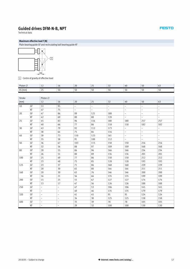
Maximum effective load F [N]
Plain-bearing guide GF and recirculating ball bearing guide KF
1 Centre of gravity of effective load
Piston 12 16 20 25 32 40 50 63
XS [mm] 25 50 50 50 50 50 50 50
Stroke Piston
[mm] 12 16 20 25 32 40 50 63
10 GF 53 95 – – – – – –
KF 47 75 – – – – – –
20 GF 47 86 99 121 188 – – –
KF 42 69 80 88 120 – – –
25 GF 45 83 96 116 180 180 257 257
KF 40 66 77 86 118 118 182 182
30 GF 43 79 92 112 173 – – –
KF 38 64 75 84 116 – – –
40 GF 39 73 110 123 161 – – –
KF 35 58 91 100 112 – – –
50 GF 36 67 103 115 150 150 216 216
KF 32 56 88 97 109 109 168 168
80 GF 28 55 86 96 166 166 234 234
KF 26 51 80 89 134 134 201 201
100 GF 25 49 77 86 150 150 212 212
KF 23 48 75 85 128 128 193 193
125 GF 23 37 71 86 168 168 229 229
KF 20 30 65 80 144 144 211 211
160 GF 20 30 63 76 146 146 200 200
KF 16 21 56 66 135 135 199 199
200 GF 15 25 55 67 127 127 174 174
KF 13 17 47 56 126 126 188 188
250 GF – – 47 53 106 106 145 145
KF – – 40 46 135 135 179 179
320 GF – – 41 45 91 91 124 124
KF – – 34 38 125 125 158 158
400 GF – – 35 39 78 78 105 105
KF – – 29 32 100 100 130 130
Subject to change – 2018/0518 � Internet: www.festo.com/catalog/...
Guided drives DFM-N-B, NPTTechnical data
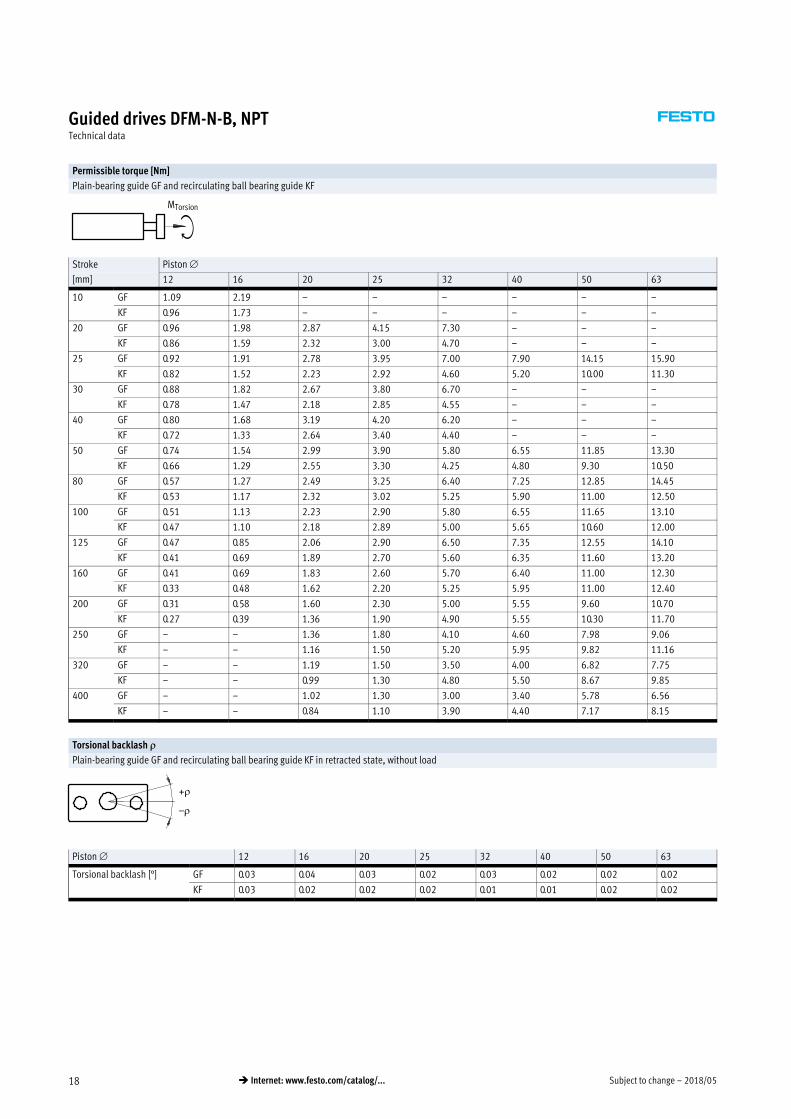
Permissible torque [Nm]
Plain-bearing guide GF and recirculating ball bearing guide KF
MTorsion
Stroke Piston
[mm] 12 16 20 25 32 40 50 63
10 GF 1.09 2.19 – – – – – –
KF 0.96 1.73 – – – – – –
20 GF 0.96 1.98 2.87 4.15 7.30 – – –
KF 0.86 1.59 2.32 3.00 4.70 – – –
25 GF 0.92 1.91 2.78 3.95 7.00 7.90 14.15 15.90
KF 0.82 1.52 2.23 2.92 4.60 5.20 10.00 11.30
30 GF 0.88 1.82 2.67 3.80 6.70 – – –
KF 0.78 1.47 2.18 2.85 4.55 – – –
40 GF 0.80 1.68 3.19 4.20 6.20 – – –
KF 0.72 1.33 2.64 3.40 4.40 – – –
50 GF 0.74 1.54 2.99 3.90 5.80 6.55 11.85 13.30
KF 0.66 1.29 2.55 3.30 4.25 4.80 9.30 10.50
80 GF 0.57 1.27 2.49 3.25 6.40 7.25 12.85 14.45
KF 0.53 1.17 2.32 3.02 5.25 5.90 11.00 12.50
100 GF 0.51 1.13 2.23 2.90 5.80 6.55 11.65 13.10
KF 0.47 1.10 2.18 2.89 5.00 5.65 10.60 12.00
125 GF 0.47 0.85 2.06 2.90 6.50 7.35 12.55 14.10
KF 0.41 0.69 1.89 2.70 5.60 6.35 11.60 13.20
160 GF 0.41 0.69 1.83 2.60 5.70 6.40 11.00 12.30
KF 0.33 0.48 1.62 2.20 5.25 5.95 11.00 12.40
200 GF 0.31 0.58 1.60 2.30 5.00 5.55 9.60 10.70
KF 0.27 0.39 1.36 1.90 4.90 5.55 10.30 11.70
250 GF – – 1.36 1.80 4.10 4.60 7.98 9.06
KF – – 1.16 1.50 5.20 5.95 9.82 11.16
320 GF – – 1.19 1.50 3.50 4.00 6.82 7.75
KF – – 0.99 1.30 4.80 5.50 8.67 9.85
400 GF – – 1.02 1.30 3.00 3.40 5.78 6.56
KF – – 0.84 1.10 3.90 4.40 7.17 8.15
Torsional backlash �
Plain-bearing guide GF and recirculating ball bearing guide KF in retracted state, without load
+�
–�
Piston 12 16 20 25 32 40 50 63
Torsional backlash [°] GF 0.03 0.04 0.03 0.02 0.03 0.02 0.02 0.02
KF 0.03 0.02 0.02 0.02 0.01 0.01 0.02 0.02

2018/05 – Subject to change 19� Internet: www.festo.com/catalog/...
Guided drives DFM-N-B, NPTTechnical data
Deflection of piston rod – Plain-bearing guide GF
Mean deflection f1 due to bearing backlash as a function of stroke l
DFM-N-GF with 2 bearings per guide rod
f = f1 + f2
f = Total deflection of piston rod
f1 = Deflection due to bearing backlash
(with production tolerance ±0.01 mm)
f2 = Deflection due to lateral force
Deflection f2 due to lateral force F as a function of stroke with plain-bearing guide GF
Stroke 50 mm
f2 [m
m]
F [N]
f2 [m
m]
F [N]
f2 [m
m]
F [N]
Stroke 100 mm
f2 [m
m]
F [N]
f2 [m
m]
F [N]
f2 [m
m]
F [N]

Subject to change – 2018/0520 � Internet: www.festo.com/catalog/...
Guided drives DFM-N-B, NPTTechnical data
Deflection of piston rod – Plain-bearing guide GF
Mean deflection f1 due to bearing backlash as a function of stroke l
DFM-N-GF with 2 bearings per guide rod
f = f1 + f2
f = Total deflection of piston rod
f1 = Deflection due to bearing backlash
(with production tolerance ±0.01 mm)
f2 = Deflection due to lateral force
Deflection f2 due to lateral force F as a function of stroke with plain-bearing guide GF
Stroke 200 mm
f2 [m
m]
F [N]
f2 [m
m]
F [N]
f2 [m
m]
F [N]
Stroke 400 mm
f2 [m
m]
F [N]
f2 [m
m]
F [N]
2018/05 – Subject to change 21� Internet: www.festo.com/catalog/...
Guided drives DFM-N-B, NPTTechnical data
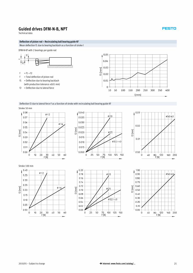
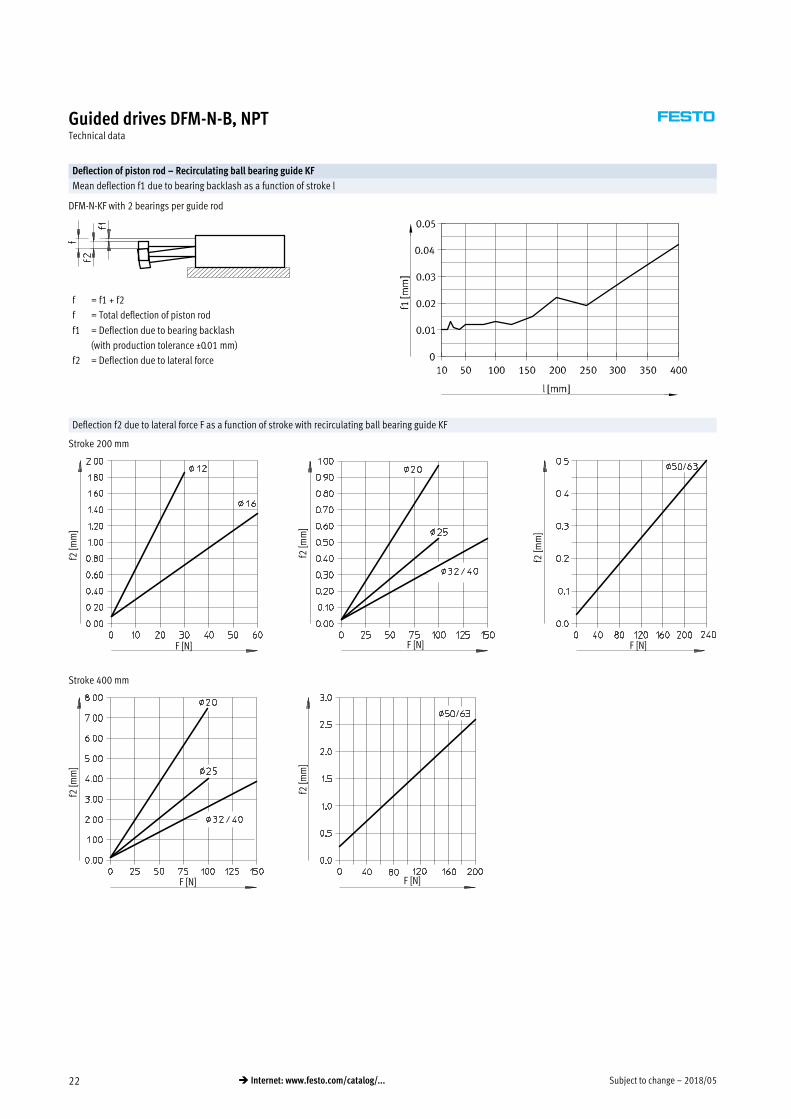
Deflection of piston rod – Recirculating ball bearing guide KF
Mean deflection f1 due to bearing backlash as a function of stroke l
DFM-N-KF with 2 bearings per guide rod
f = f1 + f2
f = Total deflection of piston rod
f1 = Deflection due to bearing backlash
(with production tolerance ±0.01 mm)
f2 = Deflection due to lateral force
Deflection f2 due to lateral force F as a function of stroke with recirculating ball bearing guide KF
Stroke 50 mm
f2 [m
m]
F [N]
f2 [m
m]
F [N]
f2 [m
m]
F [N]
Stroke 100 mm
F [N]
f2 [m
m]
f2 [m
m]
F [N]
f2 [m
m]
F [N]
Subject to change – 2018/0522 � Internet: www.festo.com/catalog/...
Guided drives DFM-N-B, NPTTechnical data
Deflection of piston rod – Recirculating ball bearing guide KF
Mean deflection f1 due to bearing backlash as a function of stroke l
DFM-N-KF with 2 bearings per guide rod
f = f1 + f2
f = Total deflection of piston rod
f1 = Deflection due to bearing backlash
(with production tolerance ±0.01 mm)
f2 = Deflection due to lateral force
Deflection f2 due to lateral force F as a function of stroke with recirculating ball bearing guide KF
Stroke 200 mm
f2 [m
m]
F [N]
f2 [m
m]
F [N] F [N]
f2 [m
m]
Stroke 400 mm
f2 [m
m]
F [N]
f2 [m
m]
F [N]

2018/05 – Subject to change 23� Internet: www.festo.com/catalog/...
Guided drives DFM-N-B, NPTTechnical data
Used as a lifting cylinder
F = Longitudinal force [N]
l = Lever arm [mm]
Permissible load with plain-bearing guide GF
Stroke 40 … 400 mm Stroke 250 … 400 mm
F [N
]
l [mm] l [mm]
F [N
]
Permissible load with recirculating ball bearing guide KF
Stroke 40 … 100 mm Stroke 125 … 200 mm
F [N
]
l [mm]
F [N
]
l [mm]
Stroke 250 … 400 mm Stroke 200 … 400 mm
l [mm]
F [N
]
l [mm]
F [N
]

Subject to change – 2018/0524 � Internet: www.festo.com/catalog/...
Guided drives DFM-N-B, NPTTechnical data
Permissible load m as a function of permissible speed v
Horizontal operation, cushioning YSRW
DFM-N-20-…-B-YSRW DFM-N-25-…-B-YSRW
v [m/s]
m [k
g]
v [m/s]
m [k
g]
DFM-N-32-…-B-YSRW DFM-N-40-…-B-YSRW
v [m/s]
m [k
g]
v [m/s]
m [k
g]
DFM-N-50-…-B-YSRW DFM-N-63-…-B-YSRW
v [m/s]
m [k
g]
25 mm stroke
100 mm stroke
200 mm stroke
400 mm strokev [m/s]
m [k
g]

2018/05 – Subject to change 25� Internet: www.festo.com/catalog/...
Guided drives DFM-N-B, NPTTechnical data
Permissible load m as a function of permissible speed v
Vertical operation, cushioning YSRW
DFM-N-20-…-B-YSRW DFM-N-25-…-B-YSRW
v [m/s]
m [k
g]
v [m/s]
m [k
g]DFM-N-32-…-B-YSRW DFM-N-40-…-B-YSRW
m [k
g]
v [m/s]
m [k
g]
v [m/s]
DFM-N-50-…-B-YSRW DFM-N-63-…-B-YSRW
m [k
g]
v [m/s]
25 mm stroke
100 mm stroke
200 mm stroke
400 mm stroke
m [k
g]
v [m/s]

Subject to change – 2018/0526 � Internet: www.festo.com/catalog/...
Guided drives DFM-N-B, NPTTechnical data
Dimensions Download CAD data � www.festo.com
12, 16 mm
1 Mounting slot for proximity
sensor SME-/SMT-8
2 Mounting slot for proximity
sensor:
12: SME-/SMT-10
16: SME-/SMT-8
3 Supply port optionally at side
or top
4 Mounting thread
5 Centring holes
6 PPV cushioning
B1 B2 B3 B4 B5 B6 B7 B8 B9 B10 B11 B12 B13 B14 B17 B22 D1
[mm] ±0.021) ±0.021)
12 60 58 44.2 4.5 51 20.5 19 20 20 9.5 41 8.5 19.5 21 25 – M5
16 67 65 45 4.5 58 22 23 23.5 20 10.5 46 9.5 21.3 24.4 28 22.5 M5
D2
D3
D4 D5
D6
D7
D8
D11
EE2) H1 H2 H3 H4 H5 H6 H7
[mm] H7 H7 GF KF H7
12 8 9 M4 5 M4 10h8 8h6 4.3 – M5 28 26 24 4 20 14 4
16 7.5 9 M5 5 M4 12h8 10h6 4.3 3.3 M5 32 30 26.5 4 24 16 7.4
H8 H9 H12 L3 L4 L5 L6 L8 L10 L12 L21 L22 T1 T2 T3 T4 T5 ß1
[mm]
12 20 14 10 10 13 14.8 11.2 21 34 5 – – 10 9.4 2.1 8 1.2 10
16 20 16 10 10 12 9.8 9.3 22 34 5 9.8 9.3 12 4.6 2.1 10 1.2 10
1) Tolerance between centring holes
2) Suitable for 10-32 UNF
2018/05 – Subject to change 27� Internet: www.festo.com/catalog/...
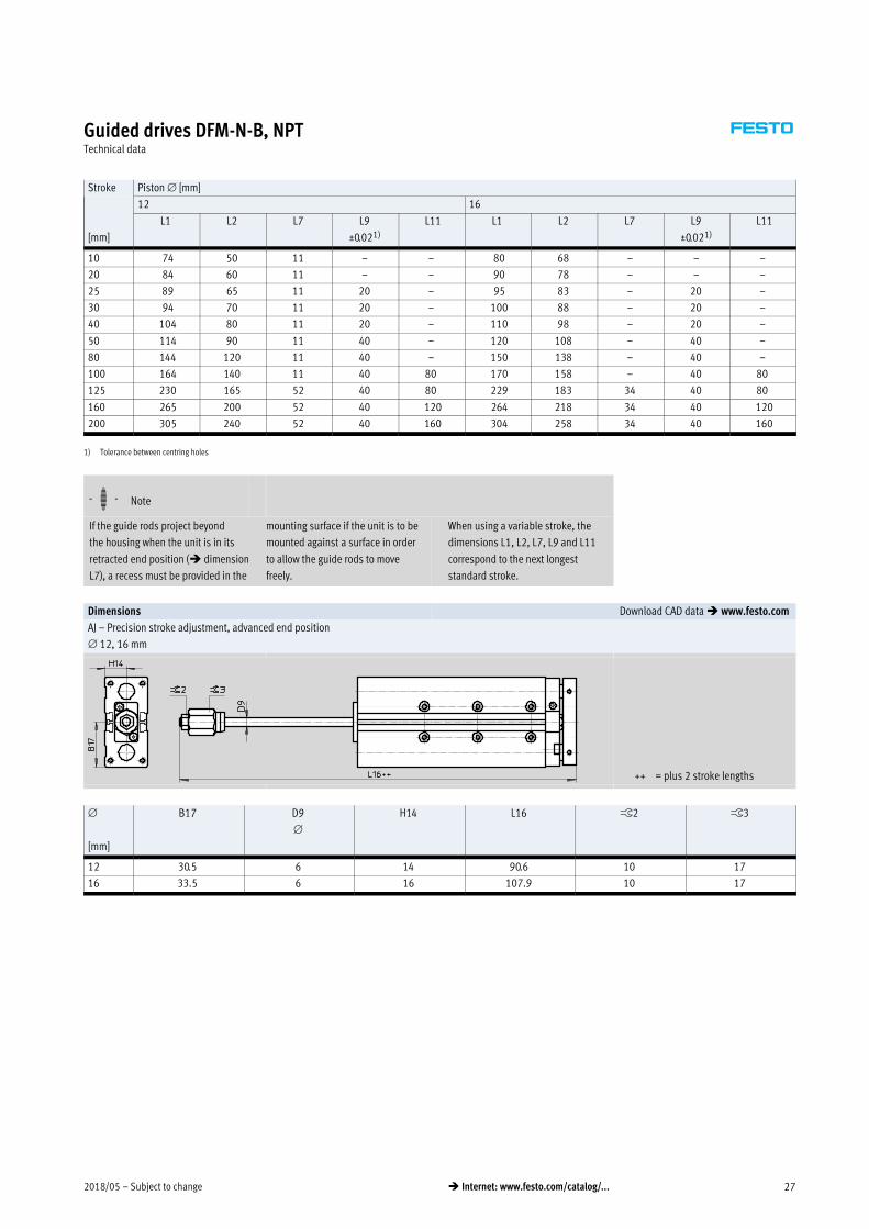
Guided drives DFM-N-B, NPTTechnical data
Stroke Piston [mm]
[mm]
12 16
L1 L2 L7 L9
±0.021)
L11 L1 L2 L7 L9
±0.021)
L11
10 74 50 11 – – 80 68 – – –
20 84 60 11 – – 90 78 – – –
25 89 65 11 20 – 95 83 – 20 –
30 94 70 11 20 – 100 88 – 20 –
40 104 80 11 20 – 110 98 – 20 –
50 114 90 11 40 – 120 108 – 40 –
80 144 120 11 40 – 150 138 – 40 –
100 164 140 11 40 80 170 158 – 40 80
125 230 165 52 40 80 229 183 34 40 80
160 265 200 52 40 120 264 218 34 40 120
200 305 240 52 40 160 304 258 34 40 160
1) Tolerance between centring holes
-H- Note
If the guide rods project beyond
the housing when the unit is in its
retracted end position (� dimension
L7), a recess must be provided in the
mounting surface if the unit is to be
mounted against a surface in order
to allow the guide rods to move
freely.
When using a variable stroke, the
dimensions L1, L2, L7, L9 and L11
correspond to the next longest
standard stroke.
Dimensions Download CAD data � www.festo.com
AJ – Precision stroke adjustment, advanced end position
12, 16 mm
++ = plus 2 stroke lengths
[mm]
B17 D9
H14 L16 ß2 ß3
12 30.5 6 14 90.6 10 17
16 33.5 6 16 107.9 10 17
Subject to change – 2018/0528 � Internet: www.festo.com/catalog/...
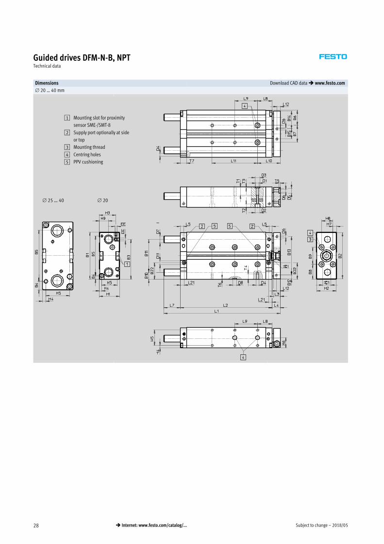
Guided drives DFM-N-B, NPTTechnical data
Dimensions Download CAD data � www.festo.com
20 … 40 mm
1 Mounting slot for proximity
sensor SME-/SMT-8
2 Supply port optionally at side
or top
3 Mounting thread
4 Centring holes
5 PPV cushioning
20 25 … 40
2018/05 – Subject to change 29� Internet: www.festo.com/catalog/...
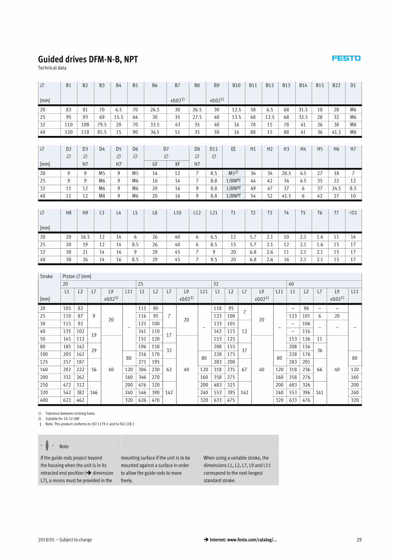
Guided drives DFM-N-B, NPTTechnical data
B1 B2 B3 B4 B5 B6 B7 B8 B9 B10 B11 B12 B13 B14 B15 B22 D1
[mm] ±0.021) ±0.021)
20 83 81 70 6.5 70 26.5 30 26.5 30 12.5 58 6.5 68 31.5 18 28 M6
25 95 93 69 15.5 64 30 35 27.5 40 13.5 68 12.5 68 32.5 28 32 M6
32 110 108 79.5 20 70 33.5 43 35 40 16 78 15 78 41 26 38 M8
40 120 118 85.5 15 90 34.5 51 35 50 16 88 15 88 41 36 41.5 M8
D2
D3
D4 D5
D6
D7
D8
D11
EE H1 H2 H3 H4 H5 H6 H7
[mm] H7 H7 GF KF H7
20 9 9 M5 9 M5 14 12 7 8.5 M52) 36 34 28.5 4.5 27 18 7
25 9 9 M6 9 M6 16 14 7 8.8 1/8NPT 44 42 34 4.5 35 22 12
32 11 12 M6 9 M6 20 16 9 8.8 1/8NPT 49 47 37 6 37 24.5 8.5
40 11 12 M8 9 M6 20 16 9 8.8 1/8NPT 54 52 41.5 6 42 27 10
H8 H9 L3 L4 L5 L8 L10 L12 L21 T1 T2 T3 T4 T5 T6 T7 ß1
[mm]
20 20 16.5 12 14 6 26 40 6 6.5 12 5.7 2.1 10 2.1 1.6 11 14
25 20 19 12 14 8.5 26 40 6 8.5 15 5.7 2.1 12 2.1 1.6 15 17
32 30 21 14 16 9 29 45 7 9 20 6.8 2.6 11 2.1 2.1 15 17
40 30 26 14 16 8.5 29 45 7 9.5 20 6.8 2.6 16 2.1 2.1 15 17
Stroke Piston [mm]
[mm]
20 25 32 40
L1 L2 L7 L9
±0.021)
L11 L1 L2 L7 L9
±0.021)
L11 L1 L2 L7 L9
±0.021)
L11 L1 L2 L7 L9
±0.021)
L11
20 105 82
920
–
111 90
720
–
118 957
20
–
– 96 – –
–
25 110 87 116 95 123 100 123 101 6 20
30 115 92 121 100 133 105
12
– 106– –
40 135 10219
141 11017
143 115 – 116
50 145 112
40
151 120
40
153 125
40
153 126 11
40
80 185 14229
196 15032
208 15537
208 15636
100 205 16280
216 17080
228 17580
228 17680
125 257 187
56
271 195
62
283 200
67
283 201
66160 292 222 120 306 230 120 318 235 120 318 236 120
200 332 262 160 346 270 160 358 275 160 358 276 160
250 472 312
146
200 476 320
142
200 483 325
142
200 483 326
141
200
320 542 382 240 546 390 240 553 395 240 553 396 240
400 622 462 320 626 470 320 633 475 320 633 476 320
1) Tolerance between centring holes
2) Suitable for 10-32 UNF
-H- Note: This product conforms to ISO 1179-1 and to ISO 228-1
-H- Note
If the guide rods project beyond
the housing when the unit is in its
retracted end position (� dimension
L7), a recess must be provided in the
mounting surface if the unit is to be
mounted against a surface in order
to allow the guide rods to move
freely.
When using a variable stroke, the
dimensions L1, L2, L7, L9 and L11
correspond to the next longest
standard stroke.
Subject to change – 2018/0530 � Internet: www.festo.com/catalog/...
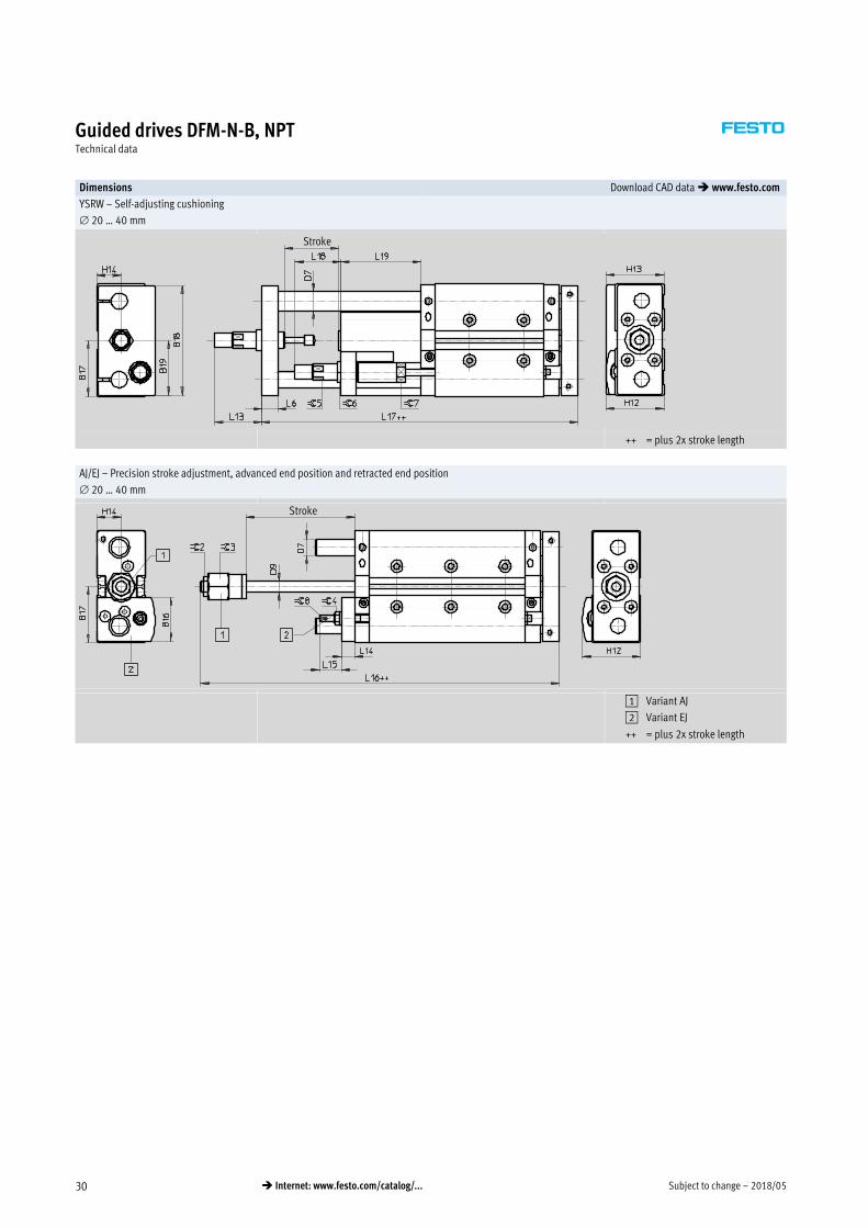
Guided drives DFM-N-B, NPTTechnical data
Dimensions Download CAD data � www.festo.com
YSRW – Self-adjusting cushioning
20 … 40 mm
Stroke
++ = plus 2x stroke length
AJ/EJ – Precision stroke adjustment, advanced end position and retracted end position
20 … 40 mm
Stroke
1 Variant AJ
2 Variant EJ
++ = plus 2x stroke length

2018/05 – Subject to change 31� Internet: www.festo.com/catalog/...
Guided drives DFM-N-B, NPTTechnical data
B16 B17 B18 B19 D7
D9
H12 H13 H14 L6 L13 L14
[mm] GF KF
20 32.5 41.5 81 40.5 14 12 8 43 43 18 12 36.5 10
25 38.6 47.5 90 45 16 14 10 49.5 50.5 22 14 43 12
32 43.4 55 105 52.5 20 16 12 56.5 56 24.5 16 52 12
40 46.2 60 116 58 20 16 12 62.5 63.5 27 16 72 12
L15 L16 L17 L18 L19 ß2 ß3 ß4 ß5 ß6 ß7 ß8
[mm]
20 16 110 153.5 34 59 13 19 8 11 15 13 2.5
25 23.5 119.5 176.5 37.5 71 17 24 13 13 17 16 4
32 18.5 129.5 190.5 48.5 76 17 30 13 15 17 19 4
40 18.5 132 209.5 55.5 95 17 30 13 20 22 27 4

Subject to change – 2018/0532 � Internet: www.festo.com/catalog/...
Guided drives DFM-N-B, NPTTechnical data
Dimensions Download CAD data � www.festo.com
50 … 63 mm
1 Mounting slot for proximity
sensors
2 Supply port optionally at side
or top
3 Mounting thread
4 Centring holes
5 PPV cushioning

2018/05 – Subject to change 33� Internet: www.festo.com/catalog/...
Guided drives DFM-N-B, NPTTechnical data
B1 B2 B3 B4 B5 B6 B7 B8 B9 B10 B11 B12 B13 B14 B15 B20 B21
[mm] ±0.021) ±0.021) ±0.021)
50 148 146 104.5 19 110 42 64 44 60 19 110 18 110 52 42 40 68
63 162 160 116.5 9 144 41 80 41 80 18.5 125 17.5 125 51 58 39.5 83
B22 D1 D2
D3
D6
D7
D11
EE2) H1 H2 H3 H4 H5 H6 H7 H8
[mm] H7 GF KF
50 52.5 M8 11 12 M8 25 20 8.8 1/4NPT 64 62 48.5 7 50 32 12 40
63 53.5 M10 15 12 M8 25 20 8.8 1/4NPT 78 76 54.5 9 60 39 19 40
H9 L3 L4 L5 L8 L10 L12 L21 T1 T2 T3 T4 T5 T6 T7 T8 ß1 ß2
[mm]
50 29 16 18 11.5 32 50 8 11.5 20 6.8 2.6 16 2.6 2.6 21 16 24 19
63 32 16 18 10.5 32 50 8 10.5 24 9 2.6 20 2.6 2.6 21 16 24 19
Stroke Piston [mm]
[mm]
50 63
L1 L2 L7 L9
±0.021)
L11 L1 L2 L7 L9
±0.021)
L11
25 137 113 6 20
–
137 114 5 20–
50 177 138 21
40
177 139 20
40
80 227 16841
227 16940 80
100 247 18880
247 189
125 293 213
62
293 214
61
120
160 328 248 120 328 249 160
200 368 288 160 368 289 200
250 495 338
139
200 495 339
138
240
320 565 408 240 565 409320
400 645 488 320 645 489
1) Tolerance between centring holes
2) Suitable for 10-32 UNF
-H- Note: This product conforms to ISO 1179-1 and to ISO 228-1
-H- Note
Since the guide rods project beyond
the housing when the unit is in its
retracted end position (� dimension
L7), a recess must be provided in the
mounting surface if the unit is to be
mounted against a surface in order to
allow the guide rods to move freely.
When using a variable stroke, the
dimensions L1, L2, L7, L9 and L11
correspond to the next longest
standard stroke.
Subject to change – 2018/0534 � Internet: www.festo.com/catalog/...
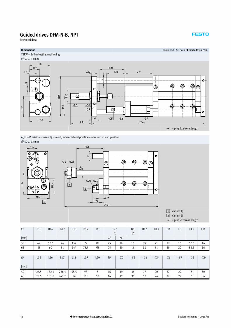
Guided drives DFM-N-B, NPTTechnical data
Dimensions Download CAD data � www.festo.com
YSRW – Self-adjusting cushioning
50 … 63 mm
++ = plus 2x stroke length
AJ/EJ – Precision stroke adjustment, advanced end position and retracted end position
50 … 63 mm
1 Variant AJ
2 Variant EJ
++ = plus 2x stroke length
B15 B16 B17 B18 B19 D6 D7
D9
H12 H13 H14 L6 L13 L14
[mm] GF KF
50 42 57.6 74 157 72 M8 25 20 16 74 71 32 16 67.6 16
63 58 60 81 144 78.5 M8 25 20 16 81 81 39 20 83.3 16
L15 L16 L17 L18 L19 L20 T9 ß2 ß3 ß4 ß5 ß6 ß7 ß8 ß9
[mm]
50 24.5 152.1 226.4 58.5 93 8 16 19 36 17 20 27 22 5 30
63 23.5 151.8 249.2 74 110 10 16 19 36 17 24 32 27 5 36
2018/05 – Subject to change 35� Internet: www.festo.com/catalog/...
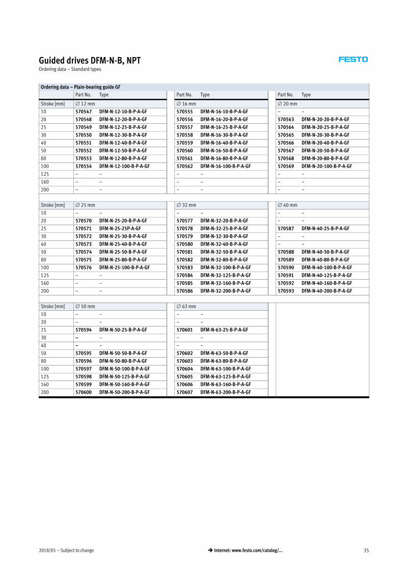
Guided drives DFM-N-B, NPTOrdering data – Standard types
Ordering data – Plain-bearing guide GF
Part No. Type Part No. Type Part No. Type
Stroke [mm] 12 mm 16 mm 20 mm
10 570547 DFM-N-12-10-B-P-A-GF 570555 DFM-N-16-10-B-P-A-GF – –
20 570548 DFM-N-12-20-B-P-A-GF 570556 DFM-N-16-20-B-P-A-GF 570563 DFM-N-20-20-B-P-A-GF
25 570549 DFM-N-12-25-B-P-A-GF 570557 DFM-N-16-25-B-P-A-GF 570564 DFM-N-20-25-B-P-A-GF
30 570550 DFM-N-12-30-B-P-A-GF 570558 DFM-N-16-30-B-P-A-GF 570565 DFM-N-20-30-B-P-A-GF
40 570551 DFM-N-12-40-B-P-A-GF 570559 DFM-N-16-40-B-P-A-GF 570566 DFM-N-20-40-B-P-A-GF
50 570552 DFM-N-12-50-B-P-A-GF 570560 DFM-N-16-50-B-P-A-GF 570567 DFM-N-20-50-B-P-A-GF
80 570553 DFM-N-12-80-B-P-A-GF 570561 DFM-N-16-80-B-P-A-GF 570568 DFM-N-20-80-B-P-A-GF
100 570554 DFM-N-12-100-B-P-A-GF 570562 DFM-N-16-100-B-P-A-GF 570569 DFM-N-20-100-B-P-A-GF
125 – – – – – –
160 – – – – – –
200 – – – – – –
Stroke [mm] 25 mm 32 mm 40 mm
10 – – – – – –
20 570570 DFM-N-25-20-B-P-A-GF 570577 DFM-N-32-20-B-P-A-GF – –
25 570571 DFM-N-25-25P-A-GF 570578 DFM-N-32-25-B-P-A-GF 570587 DFM-N-40-25-B-P-A-GF
30 570572 DFM-N-25-30-B-P-A-GF 570579 DFM-N-32-30-B-P-A-GF – –
40 570573 DFM-N-25-40-B-P-A-GF 570580 DFM-N-32-40-B-P-A-GF – –
50 570574 DFM-N-25-50-B-P-A-GF 570581 DFM-N-32-50-B-P-A-GF 570588 DFM-N-40-50-B-P-A-GF
80 570575 DFM-N-25-80-B-P-A-GF 570582 DFM-N-32-80-B-P-A-GF 570589 DFM-N-40-80-B-P-A-GF
100 570576 DFM-N-25-100-B-P-A-GF 570583 DFM-N-32-100-B-P-A-GF 570590 DFM-N-40-100-B-P-A-GF
125 – – 570584 DFM-N-32-125-B-P-A-GF 570591 DFM-N-40-125-B-P-A-GF
160 – – 570585 DFM-N-32-160-B-P-A-GF 570592 DFM-N-40-160-B-P-A-GF
200 – – 570586 DFM-N-32-200-B-P-A-GF 570593 DFM-N-40-200-B-P-A-GF
Stroke [mm] 50 mm 63 mm
10 – – – –
20 – – – –
25 570594 DFM-N-50-25-B-P-A-GF 570601 DFM-N-63-25-B-P-A-GF
30 – – – –
40 – – – –
50 570595 DFM-N-50-50-B-P-A-GF 570602 DFM-N-63-50-B-P-A-GF
80 570596 DFM-N-50-80-B-P-A-GF 570603 DFM-N-63-80-B-P-A-GF
100 570597 DFM-N-50-100-B-P-A-GF 570604 DFM-N-63-100-B-P-A-GF
125 570598 DFM-N-50-125-B-P-A-GF 570605 DFM-N-63-125-B-P-A-GF
160 570599 DFM-N-50-160-B-P-A-GF 570606 DFM-N-63-160-B-P-A-GF
200 570600 DFM-N-50-200-B-P-A-GF 570607 DFM-N-63-200-B-P-A-GF
Subject to change – 2018/0536 � Internet: www.festo.com/catalog/...
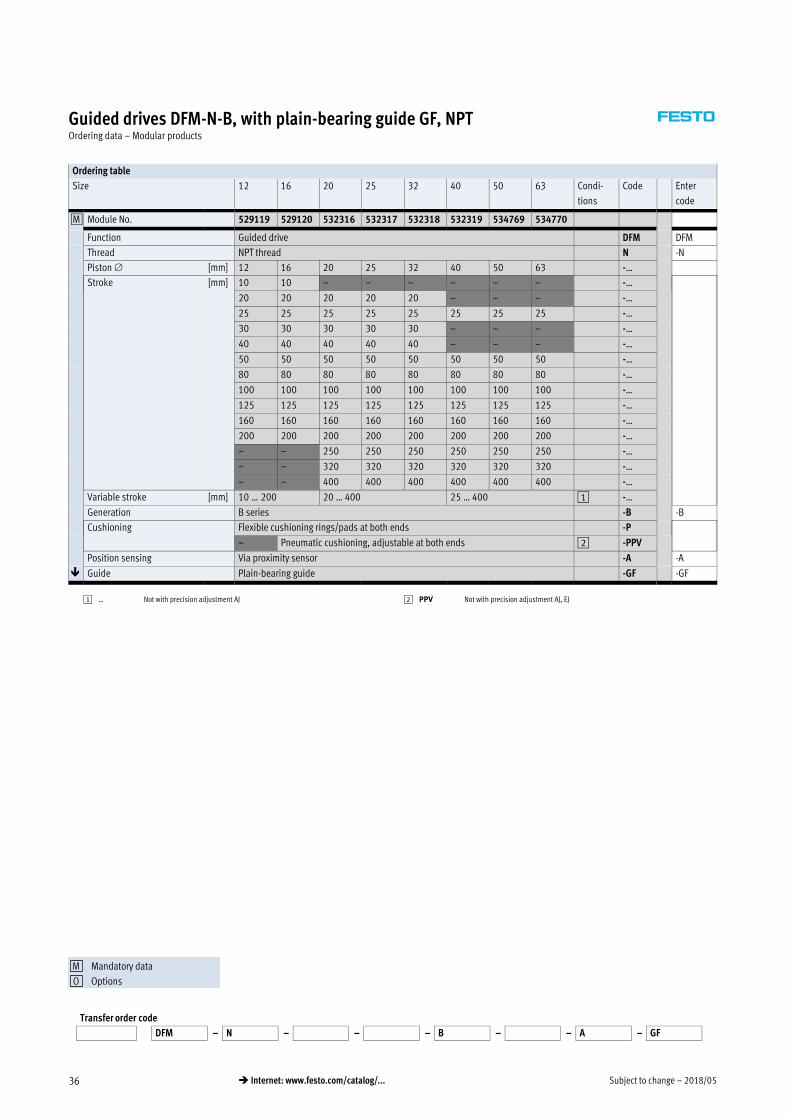
Guided drives DFM-N-B, with plain-bearing guide GF, NPTOrdering data – Modular products
Ordering table
Size 12 16 20 25 32 40 50 63 Condi
tions
Code Enter
code
0M Module No. 529119 529120 532316 532317 532318 532319 534769 534770
Function Guided drive DFM DFM
Thread NPT thread N -N
Piston [mm] 12 16 20 25 32 40 50 63 -…
Stroke [mm] 10 10 – – – – – – -…
20 20 20 20 20 – – – -…
25 25 25 25 25 25 25 25 -…
30 30 30 30 30 – – – -…
40 40 40 40 40 – – – -…
50 50 50 50 50 50 50 50 -…
80 80 80 80 80 80 80 80 -…
100 100 100 100 100 100 100 100 -…
125 125 125 125 125 125 125 125 -…
160 160 160 160 160 160 160 160 -…
200 200 200 200 200 200 200 200 -…
– – 250 250 250 250 250 250 -…
– – 320 320 320 320 320 320 -…
– – 400 400 400 400 400 400 -…
Variable stroke [mm] 10 … 200 20 … 400 25 … 400 1 -…
Generation B series -B -B
Cushioning Flexible cushioning rings/pads at both ends -P
– Pneumatic cushioning, adjustable at both ends 2 -PPV
Position sensing Via proximity sensor -A -A
� Guide Plain-bearing guide -GF -GF
1 … Not with precision adjustment AJ 2 PPV Not with precision adjustment AJ, EJ
Transfer order code
DFM – N – – – B – – A – GF
Mandatory data
Options
M
O

2018/05 – Subject to change 37� Internet: www.festo.com/catalog/...
Guided drives DFM-N-B, with plain-bearing guide GF, NPTOrdering data – Modular products
Ordering table
Size 12 16 20 25 32 40 50 63 Condi
tions
Code Enter
code
0O Temperature resistance Heat-resistant seals up to max. 120 °C 3 S6
Precision adjustment advanced Precision adjustment into the end positions, advanced -AJ
Precision adjustment retracted – – Precision adjustment into the end positions, retracted -EJ
Accessories Supplied separately ZUB- ZUB-
Slot cover for sensor slot 1 … 10 …S
Proximity sensor With cable, 2.5 m 1 … 10 …G
Contactless with
cable, 2.5 m
1 … 10 …I
3 S6 Not with precision adjustment AJ, EJ
Transfer order code
– – – ZUB –
Mandatory data
Options
M
O

Subject to change – 2018/0538 � Internet: www.festo.com/catalog/...
Guided drives DFM-B, with recirculating ball bearing guide KF, NPTOrdering data – Modular products
Ordering table
Size 12 16 20 25 32 40 50 63 Condi
tions
Code Enter
code
0M Module No. 529119 529120 532316 532317 532318 532319 534769 534770
Function Guided drive DFM DFM
Thread NPT thread N -N
Piston [mm] 12 16 20 25 32 40 50 63 -…
Stroke [mm] 10 10 – – – – – – -…
20 20 20 20 20 – – – -…
25 25 25 25 25 25 25 25 -…
30 30 30 30 30 – – – -…
40 40 40 40 40 – – – -…
50 50 50 50 50 50 50 50 -…
80 80 80 80 80 80 80 80 -…
100 100 100 100 100 100 100 100 -…
125 125 125 125 125 125 125 125 -…
160 160 160 160 160 160 160 160 -…
200 200 200 200 200 200 200 200 -…
– – 250 250 250 250 250 250 -…
– – 320 320 320 320 320 320 -…
– – 400 400 400 400 400 400 -…
Variable stroke [mm] 10 … 200 20 … 400 25 … 400 1 -…
Generation B series -B -B
Cushioning Flexible cushioning rings/pads at both ends -P
– Pneumatic cushioning, adjustable at both ends 2 -PPV
– – Shock absorber, self-adjusting, progressive 3 -YSRW
Position sensing Via proximity sensor -A -A
� Guide Recirculating ball bearing guide -KF -KF
1 … Not with precision adjustment AJ, cushioning YSRW
2 PPV Not with precision adjustment AJ, EJ
3 YSRW Not with precision adjustment AJ, EJ, since already integrated
Transfer order code
DFM – N – – – B – – A – KF
Mandatory data
Options
M
O

2018/05 – Subject to change 39� Internet: www.festo.com/catalog/...
Guided drives DFM-B, with recirculating ball bearing guide KF, NPTOrdering data – Modular products
Ordering table
Size 12 16 20 25 32 40 50 63 Condi
tions
Code Enter
code
0O Precision adjustment advanced Precision adjustment into the end positions, advanced -AJ
Precision adjustment retracted – – Precision adjustment into the end positions, retracted -EJ
Accessories Supplied separately ZUB- ZUB-
Slot cover for sensor slot 1 … 10 …S
Proximity sensor With cable, 2.5 m 1 … 10 …G
Contactless with
cable, 2.5 m
1 … 10 …I
Transfer order code
– – ZUB –
Mandatory data
Options
M
O

Subject to change – 2018/0540 � Internet: www.festo.com/catalog/...
Guided drives DFM-N-B, NPTAccessories
Centring sleeve ZBH
Material:
High-alloy steel
Dimensions and ordering data (repeat order)
B1
–0.2
D1
h7
D2
CRC1) Weight
[g]
Part No. Type PU2)
2.4 5 3.2 2 1 189652 ZBH-5 10
3 7 5.3 2 1 186717 ZBH-7 10
4 9 6.4 2 1 150927 ZBH-9 10
5 12 10.3 2 1 189653 ZBH-12 10
1) Corrosion resistance class 2 to Festo standard 940 070
Components subject to moderate corrosion stress. Externally visible parts with primarily decorative surface requirements which are in direct contact with a normal industrial environment or media such as coolants or
lubricating agents
2) Packaging unit
Centring sleeves included in the scope of delivery
DFM-N-B Piston
[mm]
Centring sleeves
For housing For yoke plate
12 2x ZBH-5, 2x ZBH-9 2x ZBH-5
16 2x ZBH-5, 2x ZBH-9 2x ZBH-5
20 2x ZBH-7, 2x ZBH-9 2x ZBH-9
25 2x ZBH-7, 2x ZBH-9 2x ZBH-9
32 2x ZBH-9, 2x ZBH-12 2x ZBH-9
40 2x ZBH-9, 2x ZBH-12 2x ZBH-9
50 2x ZBH-12 2x ZBH-12
63 2x ZBH-12 2x ZBH-12
Ordering data – Slot cover for T-slot
Assembly Length Part No. Type
Insertable from
above
2x 0.5 m 151680 ABP-5-S
2018/05 – Subject to change 41� Internet: www.festo.com/catalog/...
Guided drives DFM-N-B, NPTAccessories
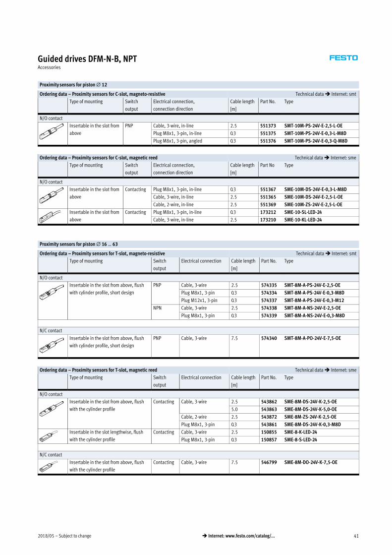
Proximity sensors for piston � 12
Ordering data – Proximity sensors for C-slot, magneto-resistive Technical data � Internet: smt
Type of mounting Switch
output
Electrical connection,
connection direction
Cable length Part No. Type
[m]
N/O contact
Insertable in the slot from
above
PNP Cable, 3-wire, in-line 2.5 551373 SMT-10M-PS-24V-E-2,5-L-OE
Plug M8x1, 3-pin, in-line 0.3 551375 SMT-10M-PS-24V-E-0,3-L-M8D
Plug M8x1, 3-pin, angled 0.3 551376 SMT-10M-PS-24V-E-0,3-Q-M8D
Ordering data – Proximity sensors for C-slot, magnetic reed Technical data � Internet: sme
Type of mounting Switch
output
Electrical connection,
connection direction
Cable length Part No Type
[m]
N/O contact
Insertable in the slot from
above
Contacting Plug M8x1, 3-pin, in-line 0.3 551367 SME-10M-DS-24V-E-0,3-L-M8D
Cable, 3-wire, in-line 2.5 551365 SME-10M-DS-24V-E-2,5-L-OE
Cable, 2-wire, in-line 2.5 551369 SME-10M-ZS-24V-E-2,5-L-OE
Insertable in the slot from
above
Contacting Plug M8x1, 3-pin, in-line 0.3 173212 SME-10-SL-LED-24
Cable, 3-wire, in-line 2.5 173210 SME-10-KL-LED-24
Proximity sensors for piston � 16 … 63
Ordering data – Proximity sensors for T-slot, magneto-resistive Technical data � Internet: smt
Type of mounting Switch
output
Electrical connection Cable length Part No. Type
[m]
N/O contact
Insertable in the slot from above, flush
with cylinder profile, short design
PNP Cable, 3-wire 2.5 574335 SMT-8M-A-PS-24V-E-2,5-OE
Plug M8x1, 3-pin 0.3 574334 SMT-8M-A-PS-24V-E-0,3-M8D
Plug M12x1, 3-pin 0.3 574337 SMT-8M-A-PS-24V-E-0,3-M12
NPN Cable, 3-wire 2.5 574338 SMT-8M-A-NS-24V-E-2,5-OE
Plug M8x1, 3-pin 0.3 574339 SMT-8M-A-NS-24V-E-0,3-M8D
N/C contact
Insertable in the slot from above, flush
with cylinder profile, short design
PNP Cable, 3-wire 7.5 574340 SMT-8M-A-PO-24V-E-7,5-OE
Ordering data – Proximity sensors for T-slot, magnetic reed Technical data � Internet: sme
Type of mounting Switch
output
Electrical connection Cable length Part No. Type
[m]
N/O contact
Insertable in the slot from above, flush
with the cylinder profile
Contacting Cable, 3-wire 2.5 543862 SME-8M-DS-24V-K-2,5-OE
5.0 543863 SME-8M-DS-24V-K-5,0-OE
Cable, 2-wire 2.5 543872 SME-8M-ZS-24V-K-2,5-OE
Plug M8x1, 3-pin 0.3 543861 SME-8M-DS-24V-K-0,3-M8D
Insertable in the slot lengthwise, flush
with the cylinder profile
Contacting Cable, 3-wire 2.5 150855 SME-8-K-LED-24
Plug M8x1, 3-pin 0.3 150857 SME-8-S-LED-24
N/C contact
Insertable in the slot from above, flush
with the cylinder profile
Contacting Cable, 3-wire 7.5 546799 SME-8M-DO-24V-K-7,5-OE

Subject to change – 2018/0542 � Internet: www.festo.com/catalog/...
Guided drives DFM-N-B, NPTAccessories
Ordering data – Connecting cables Technical data � Internet: nebu
Electrical connection, left Electrical connection, right Cable length Part No. Type
[m]
Straight socket, M8x1, 3-pin Cable, open end, 3-wire 2.5 541333 NEBU-M8G3-K-2.5-LE3
5 541334 NEBU-M8G3-K-5-LE3
Straight socket, M12x1, 5-pin Cable, open end, 3-wire 2.5 541363 NEBU-M12G5-K-2.5-LE3
5 541364 NEBU-M12G5-K-5-LE3
Angled socket, M8x1, 3-pin Cable, open end, 3-wire 2.5 541338 NEBU-M8W3-K-2.5-LE3
5 541341 NEBU-M8W3-K-5-LE3
Angled socket, M12x1, 5-pin Cable, open end, 3-wire 2.5 541367 NEBU-M12W5-K-2.5-LE3
5 541370 NEBU-M12W5-K-5-LE3
Ordering data – One-way flow control valves Technical data � Internet: grla
Connection Material Part No. Type
Thread For tubing O.D. [inch]
M51) 1/8 Plastic design2) 564839 GRLA-10-32-UNF-QB-1/8-U
5/32 Metal design3) 564840 GRLA-10-32-UNF-QB-5/32-U
1/4 564842 GRLA-10-32-UNF-QB-1/4-U
1/8NPT 5/32 534656 GRLA-1/8-QB-5/32-U
1/4 534658 GRLA-1/8-QB-1/4-U
5/16 534659 GRLA-1/8-QB-5/16-U
1/4NPT 1/4 534661 GRLA-1/4-QB-1/4-U
5/16 534662 GRLA-1/4-QB-5/16-U
3/8 190947 GRLA-1/4-NPT-QS-3/8-U
1) Suitable for 10-32 UNF
2) Operating pressure range –0.95 … +8 bar
3) Operating pressure range 1 … 9 bar

2018/05 – Subject to change 43� Internet: www.festo.com/catalog/...
Guided drives DFM-N-B, NPTAccessories
Adapter kit
DHAA, HAPB
Material:
Wrought aluminium alloy
Free of copper and PTFE
RoHS-compliant
-H- Note
The kit includes the individual
mounting interface as well as the
necessary mounting material.
Permissible drive/drive combinations with adapter kit Download CAD data � www.festo.com
Combination 1 Drive 2 Drive Adapter kit
Size Size CRC1) Part No. Type
DGC/DFM DGC DFM DHAA
1
2
25 12, 16, 20
2
562152 DHAA-D-L-25-G7-12
20, 25 32 562153 DHAA-D-L-32-G7-20
25, 32, 40 40 562154 DHAA-D-L-40-G7-25
DGPL, DGE/DFM DG… DFM HAPB
1
2
25 12, 16
2
192690 HAPB-12/16
322) 20, 25 192691 HAPB-20/25
40 32, 40 192692 HAPB-32/40
EGC/DFM EGC DFM DHAA
1
2
80 12, 16, 202
562152 DHAA-D-L-25-G7-12
120 25, 32, 40 562154 DHAA-D-L-40-G7-25
1) Corrosion resistance class CRC 2 to Festo standard FN 940070
Moderate corrosion stress. Indoor applications in which condensation may occur. External visible parts with primarily decorative requirements for the surface and which are in direct contact with the ambient atmo
sphere typical for industrial applications.
2) Omly for DGPL

Festo - Your Partner in Automation
www.festo.com
Connect with us
www.festo.com/socialmedia
1 Festo Inc. 2 Festo Pneumatic 3 Festo Corporation 4 Regional Service Center
5300 Explorer DriveMississauga, ON L4W 5G4Canada
Av. Ceylán 3,Col. Tequesquináhuac54020 Tlalnepantla, Estado de México
1377 Motor ParkwaySuite 310Islandia, NY 11749
7777 Columbia RoadMason, OH 45040
Festo Customer Interaction CenterTel: 1 877 463 3786Fax: 1 877 393 3786Email: [email protected]
Multinational Contact Center01 800 337 8669
Festo Customer Interaction Center1 800 993 37861 800 963 3786
Subj
ect t
o ch
ange


![Guided drives DFM/DFM-B · Guided drives DFM/DFM-B Product range overview Function Version Type Piston Stroke Variable stroke [mm] [mm] [mm] Double-acting DFM basic version with recirculating](https://img.pdfslide.us/doc/110x75/60075e4355302d48df775d82/guided-drives-dfmdfm-b-guided-drives-dfmdfm-b-product-range-overview-function.jpg)