Embed Size (px)
Citation preview
Government of Nepal Ministry of Urban Development
Department of Urban Developmentand Building Construction
Babarmahal, Kathmandu
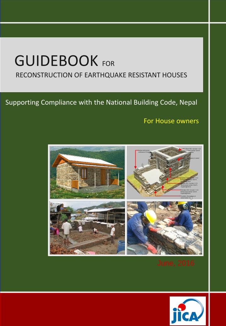
GUIDEBOOK FOR
RECONSTRUCTION OF EARTHQUAKE RESISTANT HOUSES
Supporting Compliance with the National Building Code, Nepal
June, 2016
For House owners
0
Roof Band: RCC: Concrete 1:1.5:3
Reinforcement mainbar 12mm*4,
Foop6mm@150mm
Linte l Band: RCC: Concrete 1:1.5:3
Reinforcement mainbar 12mm*4,
Foop 6mm@150mm
Vertica l reinforcement:
re inforcement 12mm rebar
Si ll Band: RCC: Concrete 1:1.5:3
Reinforcement mainbar 12mm*2,
Foop6mm@150mm
Pl inth Band: RCC: Concrete 1:1.5:3
Reinforcement mainbar 12mm*4,
Foop6mm@150mm
Foundation: Stone masonry in
cement mortar 1 :4
Wall : Stone masonry in cement
mortar 1 :4

1
1
GUIDEBOOK FOR RECONSTRUCTION OF
EARTHQUAKE RESISTANT HOUSES
Supporting Compliance with the National Building Code, Nepal
Japan International Co-operation Agency

1

Part 1.Housing reconstruction
2
Earthquake 2015
1.1 Housing reconstruction1.2 Design catalogue1.3 Earthquake1.4 Effects of earthquake on buildings1.5 Earthquake resistant design1.6 Advantage of cement mortar
Part2. The earthquake resistant house
2.1 Design of house2.2 Construction
2.2.1 Preparation of Construction2.2.2 Proper Construction process
Appendix: Models of house Design
Stone Masonry in Cement mortar 1-storey Brick Masonry in Cement mortar 1-storey Stone Masonry in Cement mortar 1-storey (option) Brick Masonry in Cement mortar 1-storey (option) Stone Masonry in Cement mortar 2-storey Brick Masonry in Cement mortar 2-storey
contents

1.1 Housing reconstruction
3
The April 25th 2015 and May 12th 2015 earthquakes in Nepalcaused widespread damage to housing in the affecteddistricts, as well as loss of life of almost 9,000 people. TheGovernment of Nepal figures indicate that 602,257 houseswere fully damaged, and 285,099 houses were partiallydamaged.
The large-scale destruction of housing resulted primarilyfrom the seismic vulnerability of un-reinforced masonryhouses that predominate throughout the country. Mosthouses (85.9% of all housing construction) are low strengthmasonry stone or brick masonry with mud mortar, withoutseismic-resilient features.Figures show the number of houses damaged in 31 districts.
62.8%23.1%
2.4%
8.7% 0.8% 2.2%
Damage of each Building type
Fully collapsedLow strength masonry
Partially damagedLow strength masonry
Fully collapsed or Beyond repairsCement based masonry
Partially damagedCement based masonry
Fully collapsed or Beyond repairsReinforced Concrete frame
Partially damagedReinforced Concrete frame

4
The Government of Nepal Post Disaster Needs Assessment(PDNA) set out principles for housing and human settlementsrecovery and reconstruction as follows:
1. Encourage the participation of communities by empoweringthem to take control of reconstruction of their houses andensuring facilitation of Owner Driven Reconstruction.
2. A comprehensive view of housing reconstruction should includeholistic habitat development, with basic services and communityinfrastructure. The principle of build back better (BBB) shouldtranslate into a concept of safer settlements.
3. Reconstruction should be seen as a vehicle to build long-termcommunity resilience by reducing vulnerabilities andstrengthening community capacities to mitigate future disastersthrough improved construction practices for the majority of thebuilding stock in the country.
4. Strengthen the local economy through reconstruction andprocesses that work to the benefit of the poor and marginalisedsections who are mostly in the informal sector. Reconstructionshould provide an opportunity for the poor to upgrade theirliving conditions.
5. Ensure sustainable and environment-friendly reconstructionprocesses, taking note of climate change, natural resourcemanagement and scientific risk assessments.
6. Ensure that rehabilitation is equitable and inclusive.
Heavy Damaged house by 25th April,2015

7
1.2 Design Catalogue forReconstruction of earthquake resistant houses
Design catalogue for reconstruction of earthquake resistanthouses has been produced by the Department of UrbanDevelopment and Building Construction (DUDBC) tosupport rural households in the reconstruction of theirhouses.The objective of this document is to provide ruralhouseholds with clear guidance regarding earthquakeresistant construction techniques and to support them tohave house designs in compliance with the NationalBuilding Code of Nepal.
Designs included in the Design Catalogue for Reconstructionof Rural Housing can be selected and used as is, theprototype designs, or can be adapted based on theparameters as defined in the National Building Code ofNepal, the flexible designs. Once a design has been selectedthis can be used by the household as part of the buildingpermit application process.

8
List of Model Houses in design catalogue Vol.1
GROUND FLOOR PLANFLOOR AREA: 39.69sqm

1.3 Earthquakes
An earthquake is a sudden and violent motion of the earthcaused by plate tectonics which lasts for a short time, andwithin a very limited region. Most earthquakes last for lessthan a minute. The larger earthquakes are followed by aseries of after shocks which also may be dangerous.
Nepal is located in a seismic area From time to timeearthquake occur which affect inadequately constructedhouses, causing major damage and in many case partial ortotal collapse.
As the Indian subcontinent pushes against Eurasia, pressure is released in the form of earthquakes. The constant crashing of the two plates forms the Himalayan mountain range.
Source: USGS; Google Earth
9

10
Gable wall collapseIn case of gable wall the triangular of wall has no restraint. Hence, whenthe force is in perpendicular direction it shakes excessively. Under suchpull and push a crack develops. In heavy shaking it can also collapse.
1.4 Effects of Earthquake on Buildings
During an earthquake, a building is shaking in all possibledirections. The shaking loosens the joints of differentcomponents of building that leads to subsequent damage orcollapse.
Typical failure pattern of masonry structure
Separation of wallsSeparation of walls at corners and T-Junctions takes place due to poorconnection between the walls.
Delamination of wallDelamination of wall is vertical separation of internal stone and externalstone through middle of wall thickness, this occurs due to mainly to theabsence of bonding elements and weak mortar filling in stone masonrywall.

11
Earthquake resistant design
Eg:.Technology for Earthquake Resistant Building Construction (Charikot, Dorakha)
Earthquake-resistant structures are designed to withstandearthquakes. while no structure can be entirely immune todamage from earthquakes.To construct earthquake resistant building no. of factors suchas site selection, shape of house, foundation, Plinth, walls,opening, vertical reinforcement, horizontal Band, roof,materials should be considered. The details of the seismicelements at different level of the buildings are clearly shownin the figure below.
11Technology for Earthquake Resistant Building Construction
(Stone in Cement Mortar)
Roof band:Rcc:Concrete 1:1.5:3 Reinforcement mainbar 12mm *4,Stirrups 6mm@150mm
Wall:Stone masonry in cement mortar 1:4
Stich Band Rcc:Concrete 1:1.5:3Reinforcement mainbar 8mm *2,Stirrups 6mm@150mm
Sill Band Rcc:Concrete 1:1.5:3Reinforcement mainbar 12mm *4,Stirrups 6mm@150mm
Lintel Band Rcc:Concrete 1:1.5:3Reinforcement mainbar 12mm *4,Stirrups 6mm@150mm
Plinth Band Rcc:Concrete 1:1.5:3Reinforcement mainbar 12mm *4,Stirrups 6mm@150mm
Foundation Stone masonry in cement mortar 1:4
Vertical reinforcement:Reinforcement 12mm rebar

12
Earthquake 2015
Seismic horizontal bandA continuous band, also called ‘ring beam’ is a RC band at different levels in all walls of the building for tying walls together to enhance box action. It improves horizontal bending resistance thereby preventing out-of-plane collapse of walls. It also helps to prevent shrinkage, temperature and settlement cracks.
The earthquake resistant house
Components of building The pictures shows the main components of building.
Earthquake happen!!!
without band with band
Effectiveness Seismic Band
Lintel band
Stitch band
Roof band
Sill band
Plinth band
Seismic Horizontal wooden band

13
1.6 Advantage of cement mortarMortar is a paste prepared by adding required quantity of water to amixture of binding material like cement and fine aggregate like sand.
Cement mortar helps to carry the weight placed on the wall and sealthe joints where it has a high degree of impermeability and is moreprone to shrinkage than others mortar.
Advantages of cement mortar over other mortars: It gives strength to masonry. It is an excellent binding material. It is easily workable. It offers good resistance to moisture It possess good plasticity. It hardens early and starts gaining strength in around 10 hours.
Cement mortar Mud mortar
Bonding Strength
Compressive Strength

14
Earthquake 2015
Part 2:The earthquake resistant house
2.1 Design of house2.2 Construction
2.2.1 Preparation of Construction2.2.2 Appropriate Construction process
15
Earthquake resistant house
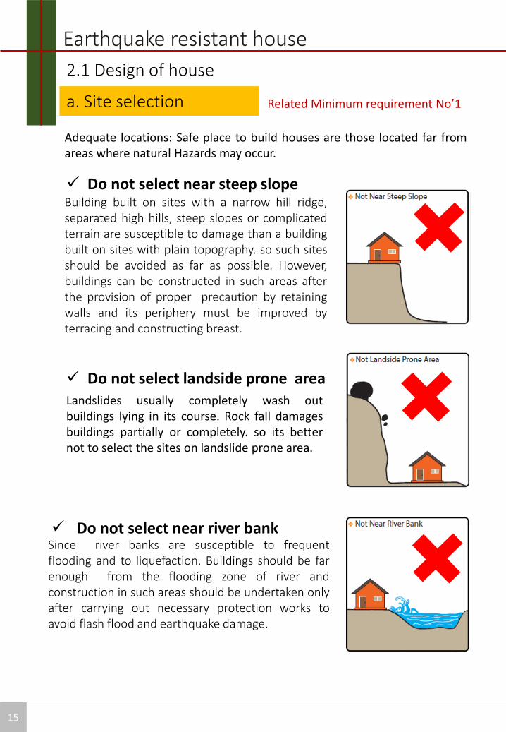
a. Site selection
Adequate locations: Safe place to build houses are those located far fromareas where natural Hazards may occur.
Building built on sites with a narrow hill ridge,separated high hills, steep slopes or complicatedterrain are susceptible to damage than a buildingbuilt on sites with plain topography. so such sitesshould be avoided as far as possible. However,buildings can be constructed in such areas afterthe provision of proper precaution by retainingwalls and its periphery must be improved byterracing and constructing breast.
Do not select landside prone area Landslides usually completely wash outbuildings lying in its course. Rock fall damagesbuildings partially or completely. so its betternot to select the sites on landslide prone area.
Do not select near steep slope
Do not select near river bankSince river banks are susceptible to frequentflooding and to liquefaction. Buildings should be farenough from the flooding zone of river andconstruction in such areas should be undertaken onlyafter carrying out necessary protection works toavoid flash flood and earthquake damage.
Related Minimum requirement No’1
2.1 Design of house

16
Site selection
In a back filled area, the bearing capacity offoundation sub soil is low and settlement offoundation may occur. Also, foundation may beexposed due to easy scouring of backfilled soil .Ifa building is to be constructed on a filled ground,the foundation should be deep enough so as torest on firm soil and not on filled up soil.
Do not select filled or soft ground
Do not select Rock fall Area
Do not select Geological fault or Ruptured Area
Do not select Liquefaction susceptible Area

b.Shape of house
17
To make earthquake resistant house successfully, design must have agood shape and an adequate distribution of walls.
The building, as a whole or its individual blocks, shall be plannedsymmetrical as far as possible.
Regularity
Symmetry
Simple rectangular shapes behave better in an earthquake than shapeswith projections. Torsional effects of ground motion are pronounced inlong narrow rectangular blocks. The length of a block shall not begreater than three times its width of the building.If longer lengths are required two separate blocks with sufficientseparation between should be provided.
According to National Building Code, Nepal, the minimum requirement that should be considered are as follows:
Related Minimum requirement No’2
Number of storey:
It shouldn’t be more than 2 storey + attic incase of the stone andbrick masonry with cement mortar
Incase of stone/brick masonry in mud mortar with wooden bandthe total number of storey should be limited to one storey whereasif R.C band is used instead of wooden band then one plus atticfloor can be constructed.
Earthquake resistant house

18
The building shouldnot be too long ortoo tall
Span of wallThe clear span of the wall shouldn’t be
more than 12 times thickness of the walland not more than 4.5 m.
Size of RoomEach room should not exceed 13.5 sq. m.
Height of wallFloor height shall not be more than 3.0m.Incase of attic floor, maximum height fromfloor level to ridge level shall be 1.8 m andmaximum height from floor level to eavelevel shall be 1.0m.
Earthquake resistant house
b.Shape of House
2.1 Design of house

C. Opening of wall
19
2.1 Design of House
Openings are the voids in walls to make them weak. so, their sizes andlocations are to be carefully decided while Construction. Some of rulesfor size and location of openings in masonry buildings are shown in nextpage. Following are the guidelines on the size and position of opening:
The total length of openingsIt should not be more than 50% of total length of the walls in case thebuilding is of single storey. But it should not be more than 42% atground floor when the building is 2 storied.
Distance of opening from the end of a wallIt should be more than ¼ of the height of the opening but not less than0.6 m.
The horizontal distance between two openingsIt should not be less than half of the height of the shorter opening, butnot less than 0.6 m.
The vertical distance between two openingsIf there are two openings in the height of a wall, then vertical distancebetween the two openings should not be less than 600 mm or 50% ofthe width of the smaller opening.] When the openings do not comply with requirements above points,
they should either be boxed around in reinforced concrete orreinforcing bars provided at the jambs through the masonry asshown in figure below
Related Minimum requirement No’8

20
Large sizes and inappropriate locations of opening are another cause ofsevere damage of masonry buildings.
Openings are the voids in walls to make them weak. so, their sizes andlocations are to be carefully decided while Construction. Some of rules forsize and location of openings in masonry buildings are shown in next page.Following are the guidelines on the size and position of opening:
The total length of openingsIt shouldn’t exceed 30% of the length of the wall between consecutivecross-walls in single storey mud masonry whereas incase of cementmasonry construction, it shouldn’t exceed 50 % in single storeyconstruction and 42% in two storey construction.
Distance of opening from the end of a wallOpenings are to be located away from inside corners by a clear distanceequal to at least ¼ of the height of the opening, but not less than 0.6m.
The horizontal distance between two openingsIt should not be less than half of the height of the shorter opening, but notless than 0.6 m.
The vertical distance between two openingsIf there are two openings in the height of a wall, then vertical distancebetween the two openings should not be less than 600 mm or 50% of thewidth of the smaller opening.
When the openings do not comply with requirements above points,they should either be boxed around in reinforced concrete orreinforcing bars provided at the jambs through the masonry as shownin figure below
C. Opening of wallRelated Minimum requirement No’8
2.1 Design of House

21
gf]6:
rf} ! + rf} @ <)=# nDafO{ ! Ps tNnfsf] nflu,)=@% nDafO{ ! Ps tNnf / a'O{unsf] nflu
rf} ^ + rf} & <)=# nDafO{ @ Ps tNnfsf] nflu,)=@% nDafO{ @ Ps tNnf / a'O{unsf] nflu
rf} $ >=)=% rf} @ t/ ^)) ld=ld eGbf sd
rf} % >=)=@% rf} ! t/ $%) ld=ld eGbf sd
Brick/ Stone masonry with mud mortar:
gf]6:rf} ! + rf} @ + rf} # <=)=% nDafO{ ! Ps tNnfsf] nflu,)=$@ nDafO{ ! b'O{ tNnfsf] nflu
rf} ^ + rf} & <=)=% nDafO{ @ Ps tNnfsf] nflu,)=$@ nDafO{ @ b'O{ tNnfsf] nflu
rf} $ >=)=% p@ t/ ^)) ld=ld eGbf sd
rf} *>=)=@% p@ t/ ^)) ld=ld eGbf sd
rf} %>=)=@% p ! t/ ^)) ld=ld eGbf sd
rf} #>=-)=% rf} @ ,)=% rf} ( / ^)) ld=ld dWosf] clwstd
rf}%rf}$ rf}$ rf}* rf}% rf}$
rf}*rf}&
rf}^
rf}#
rf}!
rf}(
p !
p #
p @
p @
p !
Brick/ Stone masonry with cement mortar:
Earthquake resistant house
2.1 Design of house

22
Laying masonryMasonry should not be laid staggered or straggled in order to avoidcontinuous vertical joints. At corners or wall junctions, through verticaljoints should be avoided by properly laying the masonry. It should beinterlocked.
Mortar MixtureMortar joints should not be more than 20mm and less than 10mm inthickness. The ratio recommend 1:6(Cement: Sand).
Through-stoneThrough-stone of a length equal to the full wall thickness should be used inevery 600 mm lift at not more than 1.2 m apart horizontally.
MASONRY TYPE MASONRY TYPE
One Two Two plus Attic
Stone 350-450 450 450
Brick 230 350 350
2.1 Design of house
d.Wall specificationRelated Minimum requirement No’5
Thickness of wall
Key Technical Points• The pressure acting on stones should be vertical.• Dressed stones are preferable than natural round shaped stones.• Broken or small stones should not be used.• Through stone should be laid in every 600mm lift and not more than
1.2m apart horizontally.• Wet stone should be used to avoid sucking moisture from mortar.• Stone should be cleaned no to loss bonding strength with mortar.• Mortar should be packed and chipped in properly without void space• Mortar joint should not be in one continuous vertical line.• The plumb bob should be used to check verticality.
Through stone

e.Seismic horizontal band:
23
Related Minimum requirement No’4,No’7 and No’8
Earthquake resistant house
2.1 Design of house
A continuous band, also called ‘ring beam’ is a RC band atdifferent levels in all walls of the building for tying walls togetherto enhance box action. It improves horizontal bending resistancethereby preventing out-of-plane collapse of walls. It also helps toprevent shrinkage, temperature and settlement cracks.
Stone in cement Mortar with R.C. band
Stone in mud Mortar with wooden band

24
Plinth bandThis band is provided where soil is soft or uneven in their properties. It mayalso serve as a damp-proof course.
Sill bandThis band is provided just below the window openings through all walls at thebottom .it becomes critical if the floor height is high.
Lintel bandA lintel band shall be provided through all walls at the top level of opening. thus the top-level of all the openings shall be made equal as far as practicable. it must be provided in all stories of the building as per table.
Roof bandThis band shall be provided at the eave-level of trussed roofs and also justbelow the joists on all such floors which consist of joists and coveringelements (flexible floors), so as to integrate them properly at their ends andfix them into the walls
Earthquake resistant house
tNnfsf] ;+Vof 808Lsf] Aof;
! tNn] !@ ld=ld
@ tNn] !^ ld=ld

25
Materials used in building construction is also one of the factoraffecting the quality of building . So quality of construction materialsused in construction has to be ensured for assuring the final quality ofconstruction. The required quality of materials should be decidedbeforehand the construction is started; generally it is decided duringplanning and designing phase. Depending upon the construction type,structural element and location of site the quality of materialsrequired should be differs.The very commonly used construction materials are shown below inpictures.
Boulder stone (River round stone)should not be used. Need treatment ofshape.
Earthquake resistant house
2.2 Construction
2.2.2 Preparation of Construction
Materials

26
Quality Check!
Stone Brick
GOOD!BAD!

21
2.2 Construction
a.Mixture of concrete
2.2.2 Appropriate Construction Process:
Related Minimum requirement No’10
Cement concrete is a mixture of cement ,sand and stone aggregates in aspecified proportions. Mixing may be done by mixer machine or by hand ,Preferable is mixing by machine as it gives uniform quality andhomogeneous concrete mix. Procedure for mixing concrete manually hasbeen explained in the following diagrams.

22
2.2 Construction
a.Mixture of concrete
2.2.2 Appropriate Construction Process:
Related Minimum requirement No’10

23
l;dG6sf] u0'f:t/
/fd|f]!g/fd|f]! g/fd|f]!
kfgLsf] dfqfdf sdL kfgLsf] clws dfqf
df]6f{/sf] ld>0f !M^ -l;d]G6 ! M afn'jf ^ dfqf_
2.2 Construction
a.Mixture of Mortar
2.2.2 Appropriate Construction Process:
Related Minimum requirement No’10
Cement Mortar is a paste prepared by adding required quantity of water to amixture of binding material like cement and fine aggregate like sand. For thepreparation of good mortar there should be quality cement, sand and waterwith appropriate proportions. Procedure to mix the mortar has beenexplained in the following diagrams.

24
Mixture of Mortar
an agfpg] tl/sf;'s]sf] an hfFRg] tl/sf
The soil for preparation of mud mortar should be free from organicmaterials. It shall also be free from pebbles and other hard materialswhich could upset the mortar thickness. The sand content in the mudshall not be more than 30 % in order to achieve a proper cohesiveness.Dry mud shall be thoroughly kneaded with water in order to prepare thedense paste.
Field Testa. Dry strength testFive or Six small balls of soil of approximately 2 cm in diameter are made.Once they are dry (after 48 hours), each ball is crushed between theforefinger and the thumb. If they are strong enough that none of thembreaks, the soil has enough clay to be used in the adobe construction,provided that some control over the mortar micro-fissures caused by thedrying process is exercised, as shown in figure below. If some of the ballsbreak, the soil is not considered to be adequate, because it does not haveenough clay and should be discarded.
Mud mortar

31
Foundation is a bottom-most part of the building whichtransfer the weight of the building to the ground. It plays vitalrole in overall stability of the structure. Foundation for aparticular structure depends on type of structure andfoundation sub soil. The foundation trench should be ofuniform width and its bed should be on same level throughoutthe flat area.
2.2 Construction
c. Foundation
2.2.2 Appropriate Construction Process:
Related Minimum requirement No’3

Foundation
Foundation for masonry Building For load bearing wall construction, strip footing of
masonry, plain concrete or RC is commonly used. RC strip footing is most effective for seismic and
settlement consideration in soft as well as firm soils. Masonry footings are most frequently used.
The depth of footing in the soil should go below the zone of deepfreezing in cold regions and below the level of shrinkage crack in clay soil.It is the most common strip foundation, which can be constructed incement or mud mortar. This type of footing is generally made of steps,the width at the bottom being more and the width at the top of thefooting is equal to the width of the wall above. The footing wall may beof brick or stone depending upon the availability of it and the mortar alsomud or the cement.
The minimum size of foundation for masonry footing in different types offoundation sub soil and different no. of stories should be as shown below
in table.
32
Types of Masonry Storey Soft Medium Hard
Brick 2-Storey 900 650 450
1-Storey 650 550 450
Stone 2-Storey - 800 600
1-Storey 800 600 600

v
$ld
tof/ e'O{ ;tx +300-Go"gtd_(Floor finish level)
tof/ hldg ;tx+±00 (finished ground level)
!=@ld=-Go"gtd_
rf} s
&%)ld
=ld
Go"gtd
d'Vo hldg ;tx
(Original ground level)
s s
pp!=@ld=-Go"gtd_
hldg dflysf] ;tx
(Superstructure level)
! — tNnf (g/d df6f])@ — tNnf (dWod df6f])
le/fnf] hldgdf hu agfpg] tl/sfsM @ ld jf ! ld6/ h'g a9L x'G5
pM #)) ld=ld= eGbf abL gxf];¥
uM clwstd 9fn @)o
vMc8¥ofpg] 6]jf kvf{n g/fVbf ! ld6/
eGbf abL gxf];¥.
#%)
80
0ld
=ld
(Go"gtd
)
%*)
^%)
!!%
#%#%
#)) -!@))
!%)
@#)
^)
!))
@$)
!!%
15
0
125
!%)
#)) -!@))
^)
!))
@$)
@$)
$% $%
%*)
#%)
!!%!!%
!!% !!%
())
#%)
! — tNnf (g/d df6f]) @ — tNnf (g/d df6f])
()) ld
=ld
(Go"gtd
)
30
0-1
20
0
*!)
Foundation Detail for Mud Mortar
@)o
*))
^)
!))
@%)
*))
-()) ld
=ld
(Go"gtd
)
#%)
$%)
&))
!@%
%)%)
27
2.2 Construction
c. Foundation
2.2.2 Proper Construction Process:

P
P la la
lala
65
0m
m
Dff]6fO{
;txsf]rf}8fO{
P = !/@ O{6fsf] nDafO{
la = !/$ O{6fsf] nDafO{
uf/f]sf] k|sf/ tNnf g/d dWod s8f
O{§f ! — tNnf &%) ^%) %%)
9'FËf
@ — tNnf - *)) ^))
! — tNnf *)) ^)) ^))
df6f]sf] k|sf/ cg'?k uf/f]af6 lgld{t husf] nflu rflxg] Go"gtd
;txsf] rf}8fO{ -ld=ld_
Dff]6fO{
#))
#))
!%)
!%)ld=ld
#))
#))
!%)
%)ld=ldX #*ld=ld
&%ld=ldX #*ld=ld
Dff]6fO{
P = ;txsf] rf}8fO{– uf/f]sf] rf}8fO{/^
O{6fsf] uf/f]df Dff6f] d;nf
9'FËfsf] uf/f]df Dff6f] d;nf
28
Foundation
Foundation Detail for Mud Mortar

35
The first important step in construction of a foundation is the layout .It isan essential procedure before the start of work. Clean the ground from allorganic or any odd elements. Then tightened the ropes using trestlesmade by wood poles nailed to a transversal stick and embed it to theground, as shown in the figure. Trestles are placed at external part ofbuild. Check the angle of 90{at the corners making triangle of 3-4-5 lengthsides} as shown here. Use chalk or gypsum powder to mark.
1. Layout plan
2. Excavation
It is important that foundation to be leveled below the ground level, onnatural soil at a depth not less than 1.0 m. If thickness of the shallowlandfill is greater than 1.0 m the trench should be over excavated until itreach the natural soil and refilled with simple concrete.
2.2 Construction
d. Construction Sequence
2.2.2 Proper Construction Process:

36
3. Laying Brick Bedding
The excavated area is then filled by a layer of brick.
4. Placing lean concrete
The layer of brick is covered by lean concrete
5. Construction of Foundation with installation of vertical Rebar
Reinforcement bars are placed and fixed into the foundation
Construction Sequence

37
After the reinforcement a layer of concrete is placed over lean concrete.
6. Construction of plinth band
7. Construction of Masonry wall and RC bands
8. Construction of Corner and transverse bands
Masonry wall is constructed above plinth band and openings are made and RCbands are placed over , middle and under masonry wall.
After the completion of the opening, the construction of the masonry wall isstopped to construct the corner and transverse band.
2.2 Construction
d. Construction Sequence

38
After the construction of wall , roof is placed over it.
11. Installation of roof
9. Construction of lintel band:
9. Construction of lintel band:
After completion of lintel band, masonry wall is constructed and above that roof band is constructed and above that timber truss is made.
A continuous lintel band is constructed through walls at the top level of opening.
Construction Sequence

39
Treatment of shape Mixing mortar
Though Stone Laying properly
Bar bending Fook 135degree
Seismic band Seismic band
40
Earthquake 2015
Part-3 Standard Design

41

42

Earthquake 2015
43

44

45

46

47

48