Embed Size (px)
Citation preview
High Voltage Cables52–145 kV
Handling and OperatingInstructions
HANDLING AND OPERATING INSTRUCTIONS HV Power Cables 52 ─ 145 kV
1 (24)
R&D Technical customer service
01.10.2010
© REKA Cables LTD. 2010-10-01. Rights for changes reserved. GtU HV52145a20101001a (en)
HANDLING AND OPERATING INSTRUCTIONS
DRYREX High voltage cables 52…145 kV
Contents
Scope of application..............................................................................................................................................3
General....................................................................................................................................................................3
Professional skills, tools and working practices ......................................................................................................3
Checking the product...............................................................................................................................................3
High voltage cable technical information .................................................................................................................4
Handling instructions............................................................................................................................................5
Packaging and how to handle cable drums.............................................................................................................5 Cable drum condition ....................................................................................................................................5 Free space with the outermost cable layer ...................................................................................................5 How to fix the cable end to the drum.............................................................................................................5 Cable coils .....................................................................................................................................................5 Low storage temperature ..............................................................................................................................5 Instructions for handling cable drums............................................................................................................5 Transporting the cable drum .........................................................................................................................6 Loading and unloading cable drums .............................................................................................................6 Rolling the cable drum...................................................................................................................................7 Unwinding and rewinding the cable from and onto the drum........................................................................7
Lowest allowed temperatures..................................................................................................................................8 During transportation .....................................................................................................................................8 When handling and installing ........................................................................................................................9
The minimum allowed bending radius .....................................................................................................................9 Repeated bending during installation pulling ................................................................................................9 One one-off even bending to the final position..............................................................................................9 When rewinding the cable ...........................................................................................................................10
Maximum tractions allowed ...................................................................................................................................10 Maximum traction with the pulling-head......................................................................................................11 Maximum traction with the pulling-stocking.................................................................................................11
Implementing installation pulling............................................................................................................................11 Managing pulling strains..............................................................................................................................11 Cable rolls and drivers.................................................................................................................................13 Maximum allowed side wall pressure..........................................................................................................13 Safety during installation pulling..................................................................................................................14
Installation formation..............................................................................................................................................14 Symmetrical trefoil installation.....................................................................................................................14 Symmetrical installation in flat formation (planar installation) .....................................................................15

HANDLING AND OPERATING INSTRUCTIONS HV Power Cables 52 ─ 145 kV
2 (24)
R&D Technical customer service
01.10.2010
© REKA Cables LTD. 2010-10-01. Rights for changes reserved. GtU HV52145a20101001a (en)
Installation in the surrounding air ................................................................................................................15
Space required for installation ...............................................................................................................................17 Cable trenches ............................................................................................................................................17 Joints and terminations ...............................................................................................................................18 Filling sand ..................................................................................................................................................18 Protective pipes for cables ..........................................................................................................................18
Protecting the cable ends ......................................................................................................................................19
Operating instructions ........................................................................................................................................19
Cable current carrying capacity .............................................................................................................................19 Basic assumptions of the load current values.............................................................................................20 Temperature monitoring using optical fibre (optional feature) ....................................................................20 Loading factors ............................................................................................................................................20 Loading factors relating to the ground installations.....................................................................................21 Correction factors for the surrounding air....................................................................................................22
Tests after installation.........................................................................................................................................23 The voltage test for the insulation ...............................................................................................................23 The oversheath voltage test ........................................................................................................................23 Measuring the optical fibre attenuation .......................................................................................................24

HANDLING AND OPERATING INSTRUCTIONS HV Power Cables 52 ─ 145 kV
3 (24)
R&D Technical customer service
01.10.2010
© REKA Cables LTD. 2010-10-01. Rights for changes reserved. GtU HV52145a20101001a (en)
HANDLING AND OPERATING INSTRUCTIONS
DRYREX High voltage cables 52…145 kV
Scope of application These handling and operating instructions relate to aluminium and copper power cables of rated voltages 52 kV ≤ Um ≤ 145 kV, manufactured by REKA Cables LTD, which are intended for fixed installation in the high voltage network. In addition to these handling and operation instructions those product-specific instructions and limits which REKA Cables LTD has published for the high voltage cable product as technical information or as product-specific specifications must be complied with.
These handling and operation instructions do not present general technical basic requirements for the cable systems nor country-specific authority regulations which must be taken into account when planning high voltage cable connections or when putting them to practice.
These handling and operation instructions do not give instructions for dimensioning the cable system nor specifying the electricity network. These issues are the planner's responsibility. The earthing arrangements for the cable system (at least from both ends – solid bonding, from one end only – single point bonding, or alternating – cross-bonding) must be taken into account at the system planning stage, and it will have an effect on the high voltage cable operating characteristics as well as on the selection and installation of the accessories. Other issues which are the responsibility of the planner are the solutions regarding the installation format, fixing and support structure of the cables and their appropriate selection, the possible use of thermally stable filling soil, use of warning tapes and warning coverings, protection of cables with gouges or protective plates etc.
These handling and operation instructions do not include the detailed installation instructions and dimensions of the cable joints and terminations; the manufacturer of the selected cable accessory must supply them according to the type of an accessory.
These handling and operation instructions do not include submarine cables nor installation or use of these products in other such special conditions, nor the aerial installation of cables on poles, or other similar solutions.
These handling and operation instructions do not release the customer/installer/user from their responsibilities.
General
Professional skills, tools and working practices Only professional and professionally trained persons are allowed to perform the cable installation work. Only tools and equipment suitable for the working practice and intended for cable installation can be used in cable installation work. The applicable working practices must be professional, intended for high voltage cables installation technique and they must follow the good installation practice. The limits given to the cable in question, as well as these operating instructions, must be taken into account when handling and installing cables.
These handling and operating instructions do not repeat those industrial safety requirements which must be taken into account according to the authority regulations when planning the work and in different stages of implementing the installation work.
Checking the product When receiving the product it must be checked immediately that the cable type and make match the delivery documents and the product order and that the product is in good condition. The testing values measured during the manufacture are presented in the testing protocols of the production batch. When starting the installation procedure, make sure that the correct products are being installed. Do not start the installation with wrong cable type or if the product is found to have defects or damages.

HANDLING AND OPERATING INSTRUCTIONS HV Power Cables 52 ─ 145 kV
4 (24)
R&D Technical customer service
01.10.2010
© REKA Cables LTD. 2010-10-01. Rights for changes reserved. GtU HV52145a20101001a (en)
High voltage cable technical information The product-specific technical information and the limits regarding the handling and use for the delivery are explained in the customer contract information. The particulars notified as nominal values are always directive theoretical values, so the tolerances caused by the production must also be taken into account. For example, to ensure the sufficient compatibility when selecting cable accessories, it is important to also take into account the actual results for the cable diameter or oversheath thickness measured for the cable during manufacturing. These are presented in the testing protocols of the production batch.
It is the responsibility of the customer who ordered the cable to inform the persons responsible for the cable installation and use about the product-specific technical information and the limits regarding the handling and use. In these handling and operating instructions the product-specific limits are primary values in comparison to the general values.

HANDLING AND OPERATING INSTRUCTIONS HV Power Cables 52 ─ 145 kV
5 (24)
R&D Technical customer service
01.10.2010
© REKA Cables LTD. 2010-10-01. Rights for changes reserved. GtU HV52145a20101001a (en)
Handling instructions Care must be taken when handling the products, and the correct rotation direction of the cable drums must also be taken into account. The industrial safety hazards which can be caused by the large sizes and bulks of the packaging, mostly the cable drums, must also be taken into account. In addition to the correct lifting and transfer methods it is required that the lifting mechanisms and equipment are sufficiently strong to carry the overall volume, and that during transportation cable drums are fastened against any unexpected movement of the load. General instructions about handling cable drums can be found in the REKA Cables LTD Drum Handling Guide (see http://www.reka.fi). For high voltage cables the large dimensions and typically large bulks of the cables and their delivery drums must be especially taken into account.
Packaging and how to handle cable drums
Cable drum condition
Take care not to damage the cable drum when handling it. It is advisable to check the exterior condition of cable drum regularly during storage and when starting the installation of the cable from the drum. The possible protective boards used for extra protection for the cable drum must not be removed until the cable is transported to the installation position ready to be installed.
Free space with the outermost cable layer
With a full drum the distance between the outermost cable layer and the earth, or the protective boards used as extra protection, must be sufficient. We recommend free space of one cable diameter or at least 5cm between the surface of outermost cable layer and the protective boarding.
How to fix the cable end to the drum
Cable ends must be attached firmly to the drum during transportation and storage. The fixing of the inner end of the cable threaded out from the flange has an effect to the free width required when handling the drums.
Cable coils
Shorter lengths of small diameter cables can be transported and stored as coils in horizontal position. Cable coils must be protected from mechanical stress, blows and direct sunlight.
The cable coil diameter must not be smaller than the smallest bending radius given for its handling and installation allows. However, high voltage cables generally have such large dimensions that it is not possible to coil them, and this is why we recommend cable drums as packaging even for smaller sized cables.
Low storage temperature
When cables are stored in lower temperatures than the lowest temperature allowed for handling, installation or transportation, cables must not be subjected to any kind of mechanical stress such as collisions, blows, bending and twisting. The cable must be allowed to warm up sufficiently before handling or transportation in order not to go below the lowest temperature limits. For larger cables the required time for the temperature to normalise can be 24 – 36 hours.
Instructions for handling cable drums
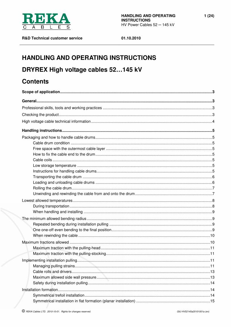
Cable drums must be stored with the barrel axis in a horizontal position, and in such a way that the drum flanges do not touch the cable in another drum. High voltage cable drums must not be stacked on top of one another.
HANDLING AND OPERATING INSTRUCTIONS HV Power Cables 52 ─ 145 kV
6 (24)
R&D Technical customer service
01.10.2010
© REKA Cables LTD. 2010-10-01. Rights for changes reserved. GtU HV52145a20101001a (en)
STORAGE VIEWED FROM ABOVE.
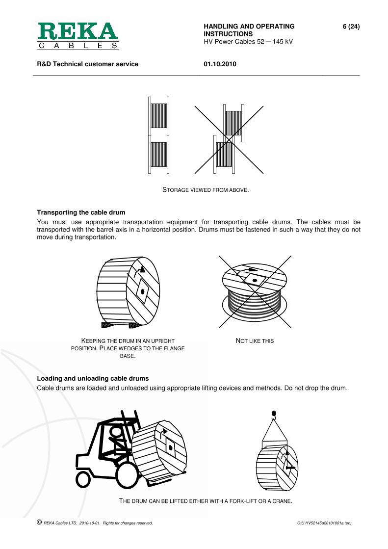
Transporting the cable drum
You must use appropriate transportation equipment for transporting cable drums. The cables must be transported with the barrel axis in a horizontal position. Drums must be fastened in such a way that they do not move during transportation.
KEEPING THE DRUM IN AN UPRIGHT
POSITION. PLACE WEDGES TO THE FLANGE
BASE.
NOT LIKE THIS
Loading and unloading cable drums
Cable drums are loaded and unloaded using appropriate lifting devices and methods. Do not drop the drum.
THE DRUM CAN BE LIFTED EITHER WITH A FORK-LIFT OR A CRANE.
HANDLING AND OPERATING INSTRUCTIONS HV Power Cables 52 ─ 145 kV
7 (24)
R&D Technical customer service
01.10.2010
© REKA Cables LTD. 2010-10-01. Rights for changes reserved. GtU HV52145a20101001a (en)
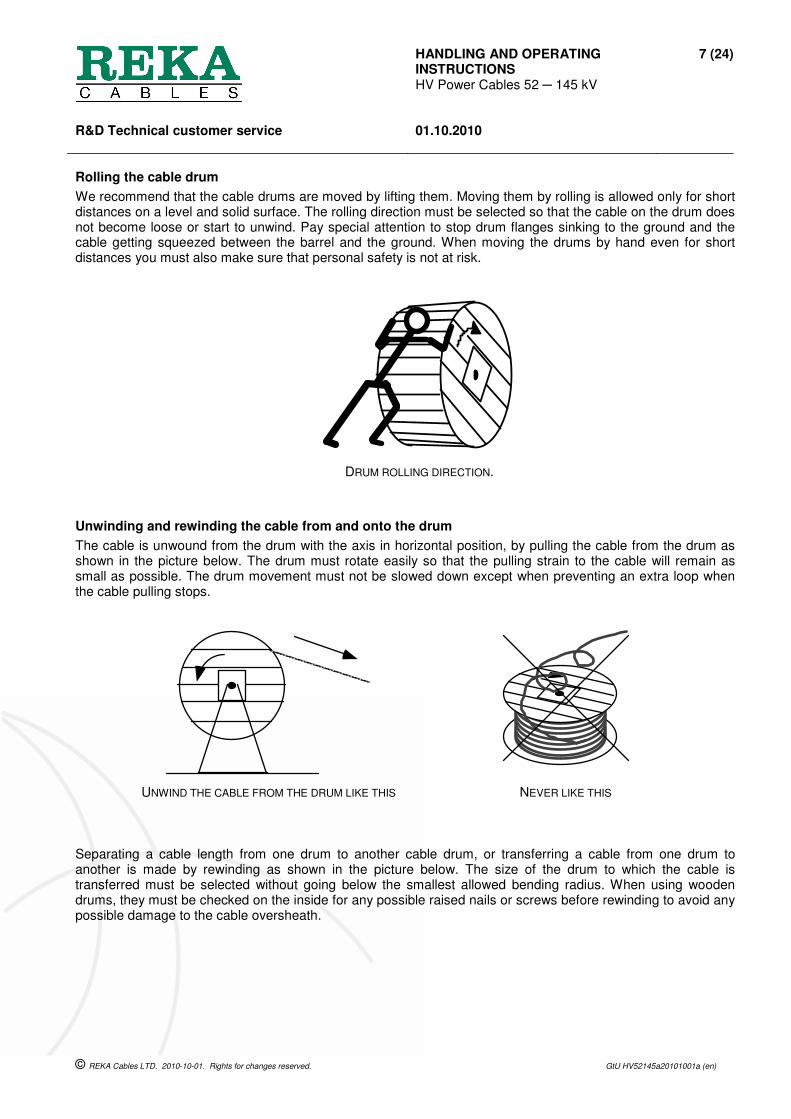
Rolling the cable drum
We recommend that the cable drums are moved by lifting them. Moving them by rolling is allowed only for short distances on a level and solid surface. The rolling direction must be selected so that the cable on the drum does not become loose or start to unwind. Pay special attention to stop drum flanges sinking to the ground and the cable getting squeezed between the barrel and the ground. When moving the drums by hand even for short distances you must also make sure that personal safety is not at risk.
DRUM ROLLING DIRECTION.
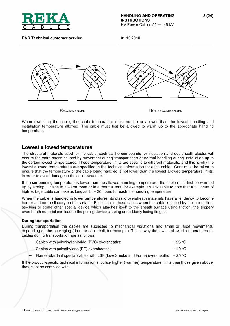
Unwinding and rewinding the cable from and onto the drum
The cable is unwound from the drum with the axis in horizontal position, by pulling the cable from the drum as shown in the picture below. The drum must rotate easily so that the pulling strain to the cable will remain as small as possible. The drum movement must not be slowed down except when preventing an extra loop when the cable pulling stops.
UNWIND THE CABLE FROM THE DRUM LIKE THIS NEVER LIKE THIS
Separating a cable length from one drum to another cable drum, or transferring a cable from one drum to another is made by rewinding as shown in the picture below. The size of the drum to which the cable is transferred must be selected without going below the smallest allowed bending radius. When using wooden drums, they must be checked on the inside for any possible raised nails or screws before rewinding to avoid any possible damage to the cable oversheath.
HANDLING AND OPERATING INSTRUCTIONS HV Power Cables 52 ─ 145 kV
8 (24)
R&D Technical customer service
01.10.2010
© REKA Cables LTD. 2010-10-01. Rights for changes reserved. GtU HV52145a20101001a (en)
RECOMMENDED NOT RECOMMENDED
When rewinding the cable, the cable temperature must not be any lower than the lowest handling and installation temperature allowed. The cable must first be allowed to warm up to the appropriate handling temperature.
Lowest allowed temperatures The structural materials used for the cable, such as the compounds for insulation and oversheath plastic, will endure the extra stress caused by movement during transportation or normal handling during installation up to the certain lowest temperatures. These temperature limits are specific to different materials, and this is why the lowest allowed temperatures are specified in the technical information for each cable. Care must be taken to ensure that the temperature of the cable being handled is not lower than the lowest allowed temperature limits, in order to avoid damage to the cable structure.
If the surrounding temperature is lower than the allowed handling temperature, the cable must first be warmed up by storing it inside in a warm room or in a thermal tent, for example. It’s advisable to note that a full drum of high voltage cable can take as long as 24 – 36 hours to reach the handling temperature.
When the cable is handled in lower temperatures, its plastic oversheath materials have a tendency to become harder and more slippery on the surface. Especially in those cases when the cable is pulled by using a pulling-stocking or some other special device which attaches itself to the sheath surface using friction, the slippery oversheath material can lead to the pulling device slipping or suddenly losing its grip.
During transportation
During transportation the cables are subjected to mechanical vibrations and small or large movements, depending on the packaging (drum or cable coil, for example). This is why the lowest allowed temperatures for cables during transportation are as follows:
─ Cables with polyvinyl chloride (PVC) oversheaths: – 25 °C
─ Cables with polyethylene (PE) oversheaths: – 40 °C
─ Flame retardant special cables with LSF (Low Smoke and Fume) oversheaths: – 25 °C
If the product-specific technical information stipulate higher (warmer) temperature limits than those given above, they must be complied with.

HANDLING AND OPERATING INSTRUCTIONS HV Power Cables 52 ─ 145 kV
9 (24)
R&D Technical customer service
01.10.2010
© REKA Cables LTD. 2010-10-01. Rights for changes reserved. GtU HV52145a20101001a (en)
When handling and installing
During handling and installation work cables are subjected to bending, tractions and abrasion of the oversheath, as well as other similar normal strains. This is why the cable temperature as a whole, or where a part of the cable is subjected to handling and the mechanical strain caused by handling, the temperature must not be below the following temperature limits:
─ Cables with polyvinyl chloride (PVC) oversheaths: – 15 °C
─ Cables with polyethylene (PE) oversheaths: – 20 °C
─ Flame retardant cables with special LSF (Low Smoke and Fume) oversheaths: – 15 °C
If the product-specific technical information stipulate higher (warmer) temperature limits than those given above, they must be complied with.
The minimum allowed bending radius The bending during the cable handling and installation cause tensile stress on the outer edge of the bending and compression stress on the inner edge of the bending to the cable components. As fixed installation cables the DRYREX high voltage cables tolerate the repeated bending during installation up to the lowest handling and installation temperature given in the product's technical information. However, as fixed installation cables they are not intended for applications where repeated bending takes place during use.
EXAMPLE. The bending radius is the measurement shown in the picture [ r ].
Repeated bending during installation pulling
During the installation pulling and installation handling the bending is allowed up to the minimum following bending radii:
─ Single-core high-voltage cables: 20 x D, where D = the outer diameter of the cable
One one-off even bending to the final position
When the high voltage cable is bent with a one even one-off bending to its final position, the minimum allowed bending radius level is 70% from the value which was allowed for the cable for the previous repeated bending. It is not, however, allowed to go below the minimum values for the bending radii given in the cable technical information.
r
HANDLING AND OPERATING INSTRUCTIONS HV Power Cables 52 ─ 145 kV
10 (24)
R&D Technical customer service
01.10.2010
© REKA Cables LTD. 2010-10-01. Rights for changes reserved. GtU HV52145a20101001a (en)
When working in cold conditions, it is also recommended that the cable part to be bent should be allowed to warm up to the minimum temperature of +5 °C, using a thermal tent, for example. The heating must never be performed by directing hot or spot-like heating, or a gas flame, to the cable or to a cable part.
When rewinding the cable
When rewinding the cable lengths after unpacking from the factory packaging on the cable coil or other cable drums, the following minimum bending radii are allowed, and they must be taken into account when forming the cable coil diameter or when selecting a suitable cable drum for rewinding:
─ Single-core high-voltage cables: 15 x D, where D = the outer diameter of the cable
When required, the diameter of the selected cable drum must be increased with sufficiently thick boarding, for example, in such a way that the bending radius of the lowest cable tier is not too small. When attaching the boarding it must be ensured that there are no raised nails or screws which could penetrate the cable oversheath.
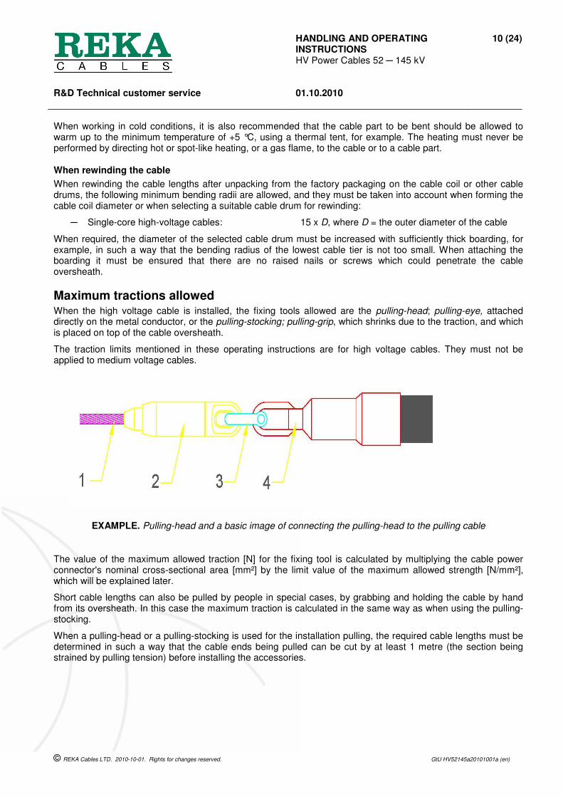
Maximum tractions allowed When the high voltage cable is installed, the fixing tools allowed are the pulling-head; pulling-eye, attached directly on the metal conductor, or the pulling-stocking; pulling-grip, which shrinks due to the traction, and which is placed on top of the cable oversheath.
The traction limits mentioned in these operating instructions are for high voltage cables. They must not be applied to medium voltage cables.
EXAMPLE. Pulling-head and a basic image of connecting the pulling-head to the pulling cable
The value of the maximum allowed traction [N] for the fixing tool is calculated by multiplying the cable power connector's nominal cross-sectional area [mm²] by the limit value of the maximum allowed strength [N/mm²], which will be explained later.
Short cable lengths can also be pulled by people in special cases, by grabbing and holding the cable by hand from its oversheath. In this case the maximum traction is calculated in the same way as when using the pulling-stocking.
When a pulling-head or a pulling-stocking is used for the installation pulling, the required cable lengths must be determined in such a way that the cable ends being pulled can be cut by at least 1 metre (the section being strained by pulling tension) before installing the accessories.

HANDLING AND OPERATING INSTRUCTIONS HV Power Cables 52 ─ 145 kV
11 (24)
R&D Technical customer service
01.10.2010
© REKA Cables LTD. 2010-10-01. Rights for changes reserved. GtU HV52145a20101001a (en)
Maximum traction with the pulling-head
When using the pulling-head attached directly to the conductor, the following maximum tractions are allowed:
a) high voltage cables with aluminium conductors:
─ The nominal cross-section area [A] of the Al-conductor is maximum 800 mm²: F = A x 70 N/mm²
─ The nominal cross-section area [A] of the Al-conductor is more than 800 mm²: F = A x 50 N/mm²
─ However, the maximum traction with the pulling-head must not exceed the value: 50000 N
b) high voltage cables with copper conductors:
─ The nominal cross-section area [A] of the Cu-conductor is maximum 1,200 mm²: F = A x 90 N/mm²
─ However, the maximum traction with the pulling-head must not exceed the value: 50,000 N
When calculating the upper limit for the traction, the cross-section area of the metallic screen or the metal sheath is not taken into account.
Example: When using a pulling-head, the theoretical traction value for the high voltage cable HXCHBMK-W 110 kV 1x630/70 would be F = 630 mm² x 90 N/mm² = 56700 N, but the maximum is determined by the upper limit 50000 N.
Maximum traction with the pulling-stocking
When using a contracting pulling-stocking attached to the top of the cable oversheath the following maximum tractions are allowed:
c) high voltage cables with aluminium conductors:
─ when the [A] of the Al-conductor is ≤ 1200 mm²: F = A x 15 N/mm²
d) high voltage cables with copper conductors:
─ when the [A] of the Cu-conductor is ≤ 1200 mm²: F = A x 20 N/mm²
However, the maximum traction with a pulling-stocking must not exceed the value: 8500 N
Example: The maximum allowed traction for the high voltage cable AHXCHBMK-W 110 kV 1x500/35, when using a pulling-stocking is F = 500 mm x 15 N/mm = 7500 N and similarly for the high voltage cable HXCHBMK 132 kV 1x1200/95 maximum 8500 N, because the limit 8500 N must not be exceeded.
Implementing installation pulling Only equipment which is sufficiently strong and safe can be used for the cable installation pulling. Care must also be taken to ensure that the strains the cable is subjected to do not exceed the limits set in the technical information. When required, cable installation tools which are intended to ease the cable motion and to reduce strain, must be used.
The cable lengths must be determined sufficient for installation pulling, and the installation pulling must be implemented in such a way that the cable ends being pulled can be cut by at least 1 metre (the section being strained by pulling tension) before the preparation work required for installing the accessories.
There must be a radio or telephone connection between the people performing the installation pulling and those supervising it, so that required instructions can be given during the pulling, or the pulling can be ordered to stop.
Managing pulling strains
During the installation work the pulling strains the cable is subjected to must be kept as low as possible. A freely rotating joint must be used between the pulling wire and the pulling-head, which allows the cable or the wire to rotate independently. During the cable pulling a measuring device (a traction meter) or a mechanical fuse which breaks due to the limit force (force indicator gauge) must be used to monitor that the maximum allowed traction for the cable is not exceeded. When using mechanical cable pulling, the pulling machine user must be connected with the traction monitoring to ensure that the allowed limit values are not exceeded.

HANDLING AND OPERATING INSTRUCTIONS HV Power Cables 52 ─ 145 kV
12 (24)
R&D Technical customer service
01.10.2010
© REKA Cables LTD. 2010-10-01. Rights for changes reserved. GtU HV52145a20101001a (en)
EXAMPLE. Basic image of a cable pulling arrangement
The motion of the cable being unwound from the drum must be monitored and directed to ensure that the cable moves along the correct route. The cable drum must turn on its axis as easily as possible to make sure that the cable is subjected to as little pulling strain as possible. The cable drum movement must be monitored and, if required, braked in such a way that if pulling slows down or stops, the cable drum does not carry on turning and cause unnecessary or tight bends or loops.
EXAMPLE. Basic image of managing the cable drum rotation
The friction of the outer surface of the cable oversheath during the installation pulling into cable protection pipes, or through feed-throughs, can be reduced by spreading lubricant on the surface. However, the lubricant must
CABLE DRUM 2. DRIVER 3. CABLE ROLL (straight) 4. CABLE WINCH (motor driven rollers) 5. CABLE ROLLS (corner) 6. CABLE PULLING MACHINE
HANDLING AND OPERATING INSTRUCTIONS HV Power Cables 52 ─ 145 kV
13 (24)
R&D Technical customer service
01.10.2010
© REKA Cables LTD. 2010-10-01. Rights for changes reserved. GtU HV52145a20101001a (en)
not be harmful to the oversheath material or the user. We recommend only water-soluble lubricants specially manufactured for cable pulling.
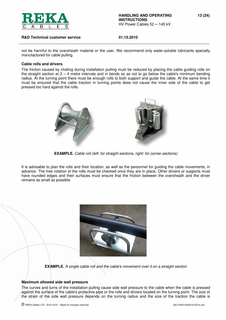
Cable rolls and drivers
The friction caused by chafing during installation pulling must be reduced by placing the cable guiding rolls on the straight section at 2 – 4 metre intervals and in bends so as not to go below the cable's minimum bending radius. At the turning point there must be enough rolls to both support and guide the cable. At the same time it must be ensured that the cable traction in turning points does not cause the inner side of the cable to get pressed too hard against the rolls.
EXAMPLE. Cable roll (left: for straight sections, right: for corner sections)
It is advisable to plan the rolls and their location, as well as the personnel for guiding the cable movements, in advance. The free rotation of the rolls must be checked once they are in place. Other drivers or supports must have rounded edges and their surfaces must ensure that the friction between the oversheath and the driver remains as small as possible.
EXAMPLE. A single cable roll and the cable's movement over it on a straight section
Maximum allowed side wall pressure
The curves and turns of the installation pulling cause side wall pressure to the cable when the cable is pressed against the surface of the cable's protective pipe or the rolls and drivers located on the turning point. The size of the strain of the side wall pressure depends on the turning radius and the size of the traction the cable is

HANDLING AND OPERATING INSTRUCTIONS HV Power Cables 52 ─ 145 kV
14 (24)
R&D Technical customer service
01.10.2010
© REKA Cables LTD. 2010-10-01. Rights for changes reserved. GtU HV52145a20101001a (en)
subjected to after the turn. The side wall pressure must be kept as small as possible by keeping the installation route as straight as possible, the radius of turning points as big as possible, and the size of the change of direction in the turning point as small as possible.
The side wall pressure is calculated case-specifically:
a) in the turns and bends against the cable rolls
─ using the formula: PSWP = T x d / r ≤ 5000 N
b) in the turns inside the plastic protective pipes or against the guiding grooves
─ using the formula: PSWP = T / r ≤ 22,000 N
where PSWP = sidewall pressure as the turning point radius [N/m]
T = cable's traction after the turn [N]
d = distance between the cable rolls [m]
r = the radius of the turn or the bend [m]
The limit values of the sidewall pressure may restrict the allowed traction for the cable and they must be taken into account.
Example: The minimum allowed bending radius for the high voltage cable AHXCHBMK-W 110 kV 1x300/70 during installation pulling is 1,46 metres. Is it possible to pull the cable with a maximum traction of 21000 N through four cable rolls which are 0,4 metres apart with a minimum bending radius of 1,46 metres? The sidewall pressure calculated according to the case a) is PSWP = 21000 N x 0,4 m / 1,46 m = 5753 N which exceeds the limit value 5000 N and therefore is not allowed. The distance between the rolls should be made shorter and the amount of rolls in the turn should be increased; the traction should be decreased or the turning radius increased.
Safety during installation pulling
The safety of the installation personnel during pulling should be noted especially, in order to ensure that the cable motion or the movement caused by the release from traction does not cause any harm to the installers. During motorised pulling the cable motion must not be touched by hand to try and prevent the movement, or in such a way that the person is at risk of being squeezed or caught.
When the installation pulling is finished, care must be taken to ensure that the cable ends do not remain open and that they are not left at the bottom of the excavation or under water, even if protected.
Installation formation The DRYREX high voltage cables intended for fixed installation can be installed as surface installations surrounded by air (for example on cable racks, cable channels or similar), or dug into the ground according to what the published technical information for the cable mentions about the product applicability.
The cable installation formations must be planned and realised as symmetrical trefoil installations or as planar installations (in flat formation).
When installing cables, care must be taken to ensure that the planned installation formation and its symmetry remains according to the plan for the whole length, even during the filling of the cable trench and afterwards. With the trefoil installation, where the cables are meant to touch each other, the installation formation can be retained more easily by using a suitable bonding tape at regular intervals to keep the cables in place.
Symmetrical trefoil installation
The phase leads of the three-phase current circuit formed by the three single-core cables are placed in such a way that the distance of one conductor centre (conductor axis) to another is equal. REKA Cables LTD declares the electrical values for trefoil installation in the installation format where the single-core cables touch each other. In this case the relative distance between conductor axes is a value which is equal to the outer diameter of a single-core cable. The values given in the product technical information are theoretical guidance values for planning and they are not deemed to be binding.

HANDLING AND OPERATING INSTRUCTIONS HV Power Cables 52 ─ 145 kV
15 (24)
R&D Technical customer service
01.10.2010
© REKA Cables LTD. 2010-10-01. Rights for changes reserved. GtU HV52145a20101001a (en)
EXAMPLE. Basic image of symmetrical trefoil installations
With the symmetric trefoil installation where the relative distance between conductors is larger, the user must calculate new values corresponding with the applied installation formations and distances, as far as the changes in the distance between cables effect them.
Asymmetrical trefoil installation leads to uneven loads on the individual phase leads, and the values calculated according to the symmetrical trefoil installation are not valid.
Symmetrical installation in flat formation (planar installation)
The phase leads of the three-phase current circuit formed by three single-core cables are placed in such a way that the conductors are on the same level and at equal distances from each other. REKA Cables LTD declares the electrical values for the planar installation in the installation format where the distance between the single-core cables is equal to the outer diameter of a single-core cable. In this case the relative distance between the conductor axels of adjacent cables equals two single-core cable outer diameters. The values given in the product technical information are theoretical guidance values for planning and they are not deemed to be binding.
EXAMPLE. Basic image of symmetrical installation in flat formation.
We do not recommend a shorter free space than the outer diameter of one cable for planar installation. With the symmetric installation in flat formation where the relative distance between conductors is different to the distance given in the technical information, the user must calculate new values corresponding with the applied installation formations and distances, as far as the changes in the distance between cables effect them.
Asymmetrical planar installation leads to uneven loads on the phase leads, and the values calculated according to the symmetrical installation in flat formation are not valid.
Installation in the surrounding air
The cables which are installed on cable racks, for example, so that they are surrounded by air, must be protected from direct sunlight, unless the heat effect caused by this has been especially taken into account when determining the current carrying capacity of the cable connection and the cable selected for installation.

HANDLING AND OPERATING INSTRUCTIONS HV Power Cables 52 ─ 145 kV
16 (24)
R&D Technical customer service
01.10.2010
© REKA Cables LTD. 2010-10-01. Rights for changes reserved. GtU HV52145a20101001a (en)
EXAMPLE. Basic image of high voltage cable installation on cable racks
The cables must be attached at 0,5 - 1.5 metre intervals in order to retain the installation formation. The clamps must be designed for cable installation and they must be suitable for the diameter of the selected cable. If the cable installation is expected to hold out against dynamic short-circuit forces, the clamps must be selected and installed in such regular intervals that the sufficient strength requirement is achieved. Determining the strength of the fastening requires that the clamps' dimensions, strengths and installation distances are known.
EXAMPLE. Cable clamps suitable for fastening
Suitable elastic softening which allows for normal heat expansion movement of a cable must be used between the cable clamps and the cable oversheath. Clamps must be tightened in such a way that the cable stays in place and the elastic softening allows for the required heat expansion movement without excessive tightening damaging a cable which is operating at its maximum operating temperature.
HANDLING AND OPERATING INSTRUCTIONS HV Power Cables 52 ─ 145 kV
17 (24)
R&D Technical customer service
01.10.2010
© REKA Cables LTD. 2010-10-01. Rights for changes reserved. GtU HV52145a20101001a (en)
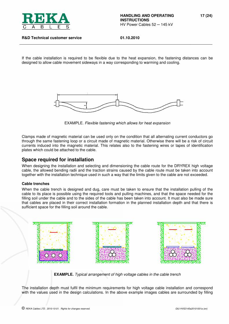
If the cable installation is required to be flexible due to the heat expansion, the fastening distances can be designed to allow cable movement sideways in a way corresponding to warming and cooling.
EXAMPLE. Flexible fastening which allows for heat expansion
Clamps made of magnetic material can be used only on the condition that all alternating current conductors go through the same fastening loop or a circuit made of magnetic material. Otherwise there will be a risk of circuit currents induced into the magnetic material. This relates also to the fastening wires or tapes of identification plates which could be attached to the cable.
Space required for installation When designing the installation and selecting and dimensioning the cable route for the DRYREX high voltage cable, the allowed bending radii and the traction strains caused by the cable route must be taken into account together with the installation technique used in such a way that the limits given to the cable are not exceeded.
Cable trenches
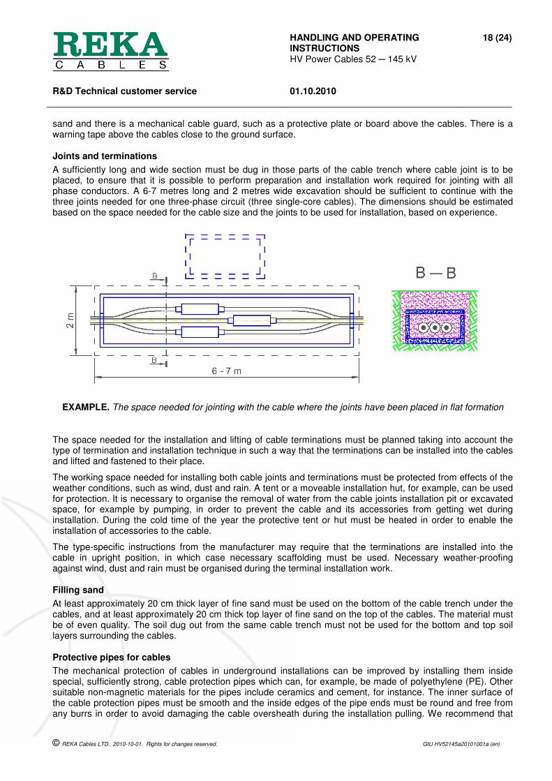
When the cable trench is designed and dug, care must be taken to ensure that the installation pulling of the cable to its place is possible using the required tools and pulling machines, and that the space needed for the filling soil under the cable and to the sides of the cable has been taken into account. It must also be made sure that cables are placed in their correct installation formation in the planned installation depth and that there is sufficient space for the filling soil around the cable.
EXAMPLE. Typical arrangement of high voltage cables in the cable trench
The installation depth must fulfil the minimum requirements for high voltage cable installation and correspond with the values used in the design calculations. In the above example images cables are surrounded by filling
HANDLING AND OPERATING INSTRUCTIONS HV Power Cables 52 ─ 145 kV
18 (24)
R&D Technical customer service
01.10.2010
© REKA Cables LTD. 2010-10-01. Rights for changes reserved. GtU HV52145a20101001a (en)
sand and there is a mechanical cable guard, such as a protective plate or board above the cables. There is a warning tape above the cables close to the ground surface.
Joints and terminations
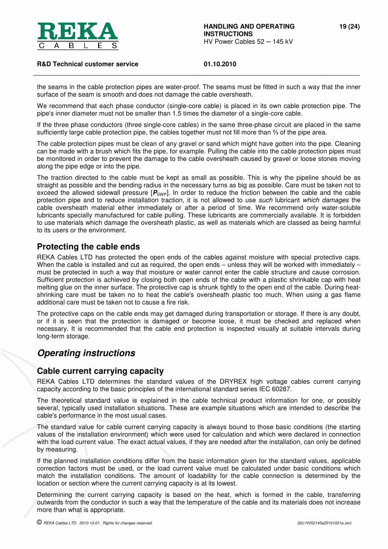
A sufficiently long and wide section must be dug in those parts of the cable trench where cable joint is to be placed, to ensure that it is possible to perform preparation and installation work required for jointing with all phase conductors. A 6-7 metres long and 2 metres wide excavation should be sufficient to continue with the three joints needed for one three-phase circuit (three single-core cables). The dimensions should be estimated based on the space needed for the cable size and the joints to be used for installation, based on experience.
EXAMPLE. The space needed for jointing with the cable where the joints have been placed in flat formation
The space needed for the installation and lifting of cable terminations must be planned taking into account the type of termination and installation technique in such a way that the terminations can be installed into the cables and lifted and fastened to their place.
The working space needed for installing both cable joints and terminations must be protected from effects of the weather conditions, such as wind, dust and rain. A tent or a moveable installation hut, for example, can be used for protection. It is necessary to organise the removal of water from the cable joints installation pit or excavated space, for example by pumping, in order to prevent the cable and its accessories from getting wet during installation. During the cold time of the year the protective tent or hut must be heated in order to enable the installation of accessories to the cable.
The type-specific instructions from the manufacturer may require that the terminations are installed into the cable in upright position, in which case necessary scaffolding must be used. Necessary weather-proofing against wind, dust and rain must be organised during the terminal installation work.
Filling sand
At least approximately 20 cm thick layer of fine sand must be used on the bottom of the cable trench under the cables, and at least approximately 20 cm thick top layer of fine sand on the top of the cables. The material must be of even quality. The soil dug out from the same cable trench must not be used for the bottom and top soil layers surrounding the cables.
Protective pipes for cables
The mechanical protection of cables in underground installations can be improved by installing them inside special, sufficiently strong, cable protection pipes which can, for example, be made of polyethylene (PE). Other suitable non-magnetic materials for the pipes include ceramics and cement, for instance. The inner surface of the cable protection pipes must be smooth and the inside edges of the pipe ends must be round and free from any burrs in order to avoid damaging the cable oversheath during the installation pulling. We recommend that
HANDLING AND OPERATING INSTRUCTIONS HV Power Cables 52 ─ 145 kV
19 (24)
R&D Technical customer service
01.10.2010
© REKA Cables LTD. 2010-10-01. Rights for changes reserved. GtU HV52145a20101001a (en)
the seams in the cable protection pipes are water-proof. The seams must be fitted in such a way that the inner surface of the seam is smooth and does not damage the cable oversheath.
We recommend that each phase conductor (single-core cable) is placed in its own cable protection pipe. The pipe's inner diameter must not be smaller than 1.5 times the diameter of a single-core cable.
If the three phase conductors (three single-core cables) in the same three-phase circuit are placed in the same sufficiently large cable protection pipe, the cables together must not fill more than ⅔ of the pipe area.
The cable protection pipes must be clean of any gravel or sand which might have gotten into the pipe. Cleaning can be made with a brush which fits the pipe, for example. Pulling the cable into the cable protection pipes must be monitored in order to prevent the damage to the cable oversheath caused by gravel or loose stones moving along the pipe edge or into the pipe.
The traction directed to the cable must be kept as small as possible. This is why the pipeline should be as straight as possible and the bending radius in the necessary turns as big as possible. Care must be taken not to exceed the allowed sidewall pressure [PSWP]. In order to reduce the friction between the cable and the cable protection pipe and to reduce installation traction, it is not allowed to use such lubricant which damages the cable oversheath material either immediately or after a period of time. We recommend only water-soluble lubricants specially manufactured for cable pulling. These lubricants are commercially available. It is forbidden to use materials which damage the oversheath plastic, as well as materials which are classed as being harmful to its users or the environment.
Protecting the cable ends REKA Cables LTD has protected the open ends of the cables against moisture with special protective caps. When the cable is installed and cut as required, the open ends – unless they will be worked with immediately – must be protected in such a way that moisture or water cannot enter the cable structure and cause corrosion. Sufficient protection is achieved by closing both open ends of the cable with a plastic shrinkable cap with heat melting glue on the inner surface. The protective cap is shrunk tightly to the open end of the cable. During heat-shrinking care must be taken no to heat the cable's oversheath plastic too much. When using a gas flame additional care must be taken not to cause a fire risk.
The protective caps on the cable ends may get damaged during transportation or storage. If there is any doubt, or if it is seen that the protection is damaged or become loose, it must be checked and replaced when necessary. It is recommended that the cable end protection is inspected visually at suitable intervals during long-term storage.
Operating instructions
Cable current carrying capacity REKA Cables LTD determines the standard values of the DRYREX high voltage cables current carrying capacity according to the basic principles of the international standard series IEC 60287.
The theoretical standard value is explained in the cable technical product information for one, or possibly several, typically used installation situations. These are example situations which are intended to describe the cable's performance in the most usual cases.
The standard value for cable current carrying capacity is always bound to those basic conditions (the starting values of the installation environment) which were used for calculation and which were declared in connection with the load current value. The exact actual values, if they are needed after the installation, can only be defined by measuring.
If the planned installation conditions differ from the basic information given for the standard values, applicable correction factors must be used, or the load current value must be calculated under basic conditions which match the installation conditions. The amount of loadability for the cable connection is determined by the location or section where the current carrying capacity is at its lowest.
Determining the current carrying capacity is based on the heat, which is formed in the cable, transferring outwards from the conductor in such a way that the temperature of the cable and its materials does not increase more than what is appropriate.
HANDLING AND OPERATING INSTRUCTIONS HV Power Cables 52 ─ 145 kV
20 (24)
R&D Technical customer service
01.10.2010
© REKA Cables LTD. 2010-10-01. Rights for changes reserved. GtU HV52145a20101001a (en)
Basic assumptions of the load current values
The DRYREX high voltage cable technical product information or technical specifications explain in which basic condition the standard value of the current carrying capacity is calculated, typically when:
─ three single-core cables are installed directly into the ground,
─ the soil temperature is +15 °C,
─ the soil heat resistivity is 1,0 K.m/W,
─ the installation depth is 1,0 metres,
─ when the installation formation is a symmetrical trefoil installation with cables touching each other,
─ and when the installation formation is a symmetrical installation in flat formation, the free space between cables equalling one diameter,
─ the cable's metallic screen circuit is closed (connected together and earthed at least in both ends of the connection), and
─ primarily when the operational temperature of the conductor is +65 °C to avoid the risk of the ground drying out and the strong increase of the soil heat resistivity which slows down heat transfer, as well as,
─ secondarily, when the operational temperature of the conductor is +90 °C, and presuming that there is no risk of the ground drying out, the responsibility of which belongs to the cable user, or when
─ one cable group is installed in free-flowing surrounding air with the temperature of +25 °C and when the cable conductor's operational temperature is +90 °C,
─ the continuous loading of the cable is applied (100 % load factor) according to the international standard series IEC 60287.
The current carrying capacity values for the cables are theoretical and they are based on the cable structure and dimensions, as well as the basic assumptions listed above. Calculations assume that the electrical network frequency is 50 Hz.
It is only possible to determine the more exact calculatory maximum value for the practical loadability, if the cable installation environment parameter values are known for the whole route, and when they remain stable. This kind of accuracy is not usually possible, which is why it is advisable to use an appropriate backup tolerance to the maximum current carrying capacity value when selecting the cable size, in order to avoid any surprises caused by the overheating of the cable connection or a single location (hot-spot).
Temperature monitoring using optical fibre (optional feature)
A specially ordered optical fibre used for measuring the cable temperature can be located to the DRYREX high voltage cable metallic screen, and it can be connected to special commercially available monitoring equipment. This arrangement enables the monitoring of the cable connection temperature in such a way as not to exceed the maximum allowed temperature for the cable, and the controlled loadability matching the maximum allowed temperature can be used.
It is, however, advisable to note that when the operational temperature for the cable is increased, the losses created in the cable are also increased. Therefore, selecting the nominal cross-sectional area to keep the cable continuously on the maximum load can become uneconomical over a longer period.
Loading factors
Determining the current carrying capacity of a high voltage cable in installation conditions which differ from the basic assumptions listed above and used for calculations, can be made using correction factors. The current carrying capacity value according to the above mentioned basic assumptions must be multiplied with the loading factors according to the relevant installation conditions parameters (see the tables below).

HANDLING AND OPERATING INSTRUCTIONS HV Power Cables 52 ─ 145 kV
21 (24)
R&D Technical customer service
01.10.2010
© REKA Cables LTD. 2010-10-01. Rights for changes reserved. GtU HV52145a20101001a (en)
Loading factors relating to the ground installations
CORRECTION FACTORS FOR DIFFERENT INSTALLATION DEPTHS
Installation depth [ metres ] 0,50 – 0,70 0,71 – 0,90 0,91 – 1,10 1,11 – 1.30 1,31 – 1,50
Correction factor 1,05 1,02 1,00 0,97 0,95
CORRECTION FACTORS FOR THE DIFFERENT SOIL HEAT RESISTIVITIES
Soil heat resistivity [ K.m/W ] 0,7 1,0 1,2 1,5 2,0 2,5 3,0
Correction factor 1,10 1,00 0,92 0,85 0,75 0,69 0,63
EXAMPLES OF DIFFERENT SOIL MATERIAL HEAT RESISTIVITIES
Dry sand (moisture content 0%) [K.m/W] : 3,0
Dry gravel and clay [K.m/W] : 1,5
Medium dry gravel and sand (moisture content 10%)
[K.m/W] : 1,2
Medium dry and damp gravel [K.m/W] : 1,0
Damp clay and sand (moisture content 25%) [K.m/W] : 0,7
CORRECTION FACTORS FOR DIFFERENT SOIL TEMPERATURES
The conductor Soil temperature
temperature –5°C 0°C +5°C +10°C +15°C +20°C +25°C +30°C +35°C +40°C +45°C
+90°C 1,13 1,10 1,06 1,03 1,00 0,96 0,93 0,89 0,86 0,82 0,77
+80°C 1,14 1,11 1,07 1,04 1,00 0,96 0,92 0,88 0,83 0,78 0,73
+70°C 1,17 1,13 1,09 1,04 1,00 0,95 0,90 0,85 0,80 0,73 0,67
+65°C 1,18 1,14 1,10 1,05 1,00 0,95 0,89 0,84 0,77 0,71 0,63
HANDLING AND OPERATING INSTRUCTIONS HV Power Cables 52 ─ 145 kV
22 (24)
R&D Technical customer service
01.10.2010
© REKA Cables LTD. 2010-10-01. Rights for changes reserved. GtU HV52145a20101001a (en)
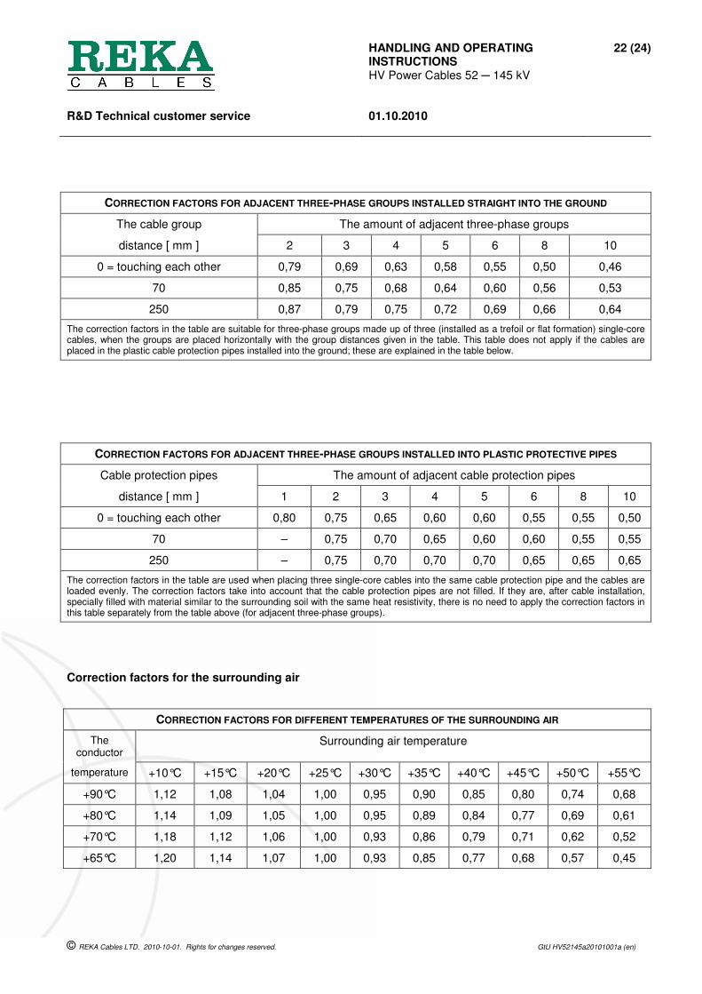
CORRECTION FACTORS FOR ADJACENT THREE-PHASE GROUPS INSTALLED STRAIGHT INTO THE GROUND
The cable group The amount of adjacent three-phase groups
distance [ mm ] 2 3 4 5 6 8 10
0 = touching each other 0,79 0,69 0,63 0,58 0,55 0,50 0,46
70 0,85 0,75 0,68 0,64 0,60 0,56 0,53
250 0,87 0,79 0,75 0,72 0,69 0,66 0,64
The correction factors in the table are suitable for three-phase groups made up of three (installed as a trefoil or flat formation) single-core cables, when the groups are placed horizontally with the group distances given in the table. This table does not apply if the cables are placed in the plastic cable protection pipes installed into the ground; these are explained in the table below.
CORRECTION FACTORS FOR ADJACENT THREE-PHASE GROUPS INSTALLED INTO PLASTIC PROTECTIVE PIPES
Cable protection pipes The amount of adjacent cable protection pipes
distance [ mm ] 1 2 3 4 5 6 8 10
0 = touching each other 0,80 0,75 0,65 0,60 0,60 0,55 0,55 0,50
70 – 0,75 0,70 0,65 0,60 0,60 0,55 0,55
250 – 0,75 0,70 0,70 0,70 0,65 0,65 0,65
The correction factors in the table are used when placing three single-core cables into the same cable protection pipe and the cables are loaded evenly. The correction factors take into account that the cable protection pipes are not filled. If they are, after cable installation, specially filled with material similar to the surrounding soil with the same heat resistivity, there is no need to apply the correction factors in this table separately from the table above (for adjacent three-phase groups).
Correction factors for the surrounding air
CORRECTION FACTORS FOR DIFFERENT TEMPERATURES OF THE SURROUNDING AIR
The conductor
Surrounding air temperature
temperature +10°C +15°C +20°C +25°C +30°C +35°C +40°C +45°C +50°C +55°C
+90°C 1,12 1,08 1,04 1,00 0,95 0,90 0,85 0,80 0,74 0,68
+80°C 1,14 1,09 1,05 1,00 0,95 0,89 0,84 0,77 0,69 0,61
+70°C 1,18 1,12 1,06 1,00 0,93 0,86 0,79 0,71 0,62 0,52
+65°C 1,20 1,14 1,07 1,00 0,93 0,85 0,77 0,68 0,57 0,45

HANDLING AND OPERATING INSTRUCTIONS HV Power Cables 52 ─ 145 kV
23 (24)
R&D Technical customer service
01.10.2010
© REKA Cables LTD. 2010-10-01. Rights for changes reserved. GtU HV52145a20101001a (en)
Tests after installation The testing after installation with voltage tests means testing both the cable and its accessories together. REKA Cables LTD has tested all supplied cable lengths with high voltage testing in the factory. If the user wishes, for special reasons, to test the installed cable and the assembly of the accessories connected to it, it can be done for the cable as mentioned hereafter.
The voltage test for the insulation
The condition of the cable insulation was tested at the factory using partial discharge measurement and the high-voltage test. The condition of the cable insulation can also be verified with the alternating voltage test (a.c.-voltage test) performed after the cable system installation, according to the international standard IEC 60840:2004 section 15.2 as follows:
Sinusoidal a.c.-voltage (frequency 20…300 Hz) is connected to the cable for one hour. There must not be any breakdown during testing. The value of the a.c.-test voltage is determined based on the cable's nominal voltage level Um according to the IEC 60840:2004 table 4 as follows:
The maximum allowed operating voltage for the
cable, Um
[ kV ]
Test-voltage (a.c.) in the 1 hour insulation
voltage-test
[ kV ]
52 52
72,5 72
123 128
145 132
Alternatively the a.c.-voltage test for insulation can be made by connecting the nominal voltage U0 to the cable without an extra load for 24 hours. There must not be any discharge during testing.
CAUTION. An old-fashioned direct current test (d.c.-voltage test of insulation) for the insulation system is not recommended, because it can cause damage to the cable accessories connected to the cable system due to the effect of the direct voltage component on the interface between them. For this same reason the direct voltage test has been removed from the international standard IEC 60840 testing methods.
The charge accumulated in the cable insulation during the alternating voltage test for insulation can be discharged by earthing both the connector and the metallic screen, or by connecting them to each other for at least one hour.
The oversheath voltage test
If there is a special reason to suspect that the cable oversheath might have been damaged during the installation, but it is not possible to pinpoint the damage visually, the cable oversheath can be tested with the direct voltage test (d.c.-voltage test) using the method according to the standard IEC 60840:2004, section 15.1. However, reliable oversheath d.c.-voltage testing requires either exceptionally good conductivity from the soil into which the cable is installed, or alternatively connectivity from the surface of the cable oversheath using, for example, a specially made semiconducting surface layer.
The value of the d.c.-test-voltage for the cable oversheath d.c.-voltage test is determined based on the nominal value of the sheath thickness, 4 kV per millimetre of thickness. However, the upper limit for the d.c.-test-voltage is maximum 10 kV (d.c.). For the oversheath d.c.-voltage test the test-voltage is connected between the cable metallic screen and the soil surrounding the cable for 1 minute. There must not be any breakdown during testing.
In order to perform the oversheath d.c.-voltage test, all metallic layers of the metallic screen (such as copper wires and any metallic laminate acting as the moisture barrier) must be connected to each other.
HANDLING AND OPERATING INSTRUCTIONS HV Power Cables 52 ─ 145 kV
24 (24)
R&D Technical customer service
01.10.2010
© REKA Cables LTD. 2010-10-01. Rights for changes reserved. GtU HV52145a20101001a (en)
We recommend that the oversheath d.c.-voltage test is performed for each pulling length separately, immediately after the cable trench has been prefilled and before the accessories, such as cable joints, have been installed.
When performing the oversheath d.c.-voltage test, it must be noted that if a conducting surface layer (optional feature) is used for the cable oversheath to be tested, it must be peeled off for a distance of 50 – 100 mm from both ends of the cable so that there is no test-voltage flashover from the oversheath surface to the metallic screen at the cable cutting points. The cable ends must also be left raised at least 50 cm from the ground. For industrial safety reasons it must be ensured that the cable and its surroundings are free from any people during the voltage-test.
There must be a break of minimum 5 minutes immediately after the test-voltage is switched off, during which the cable's metallic screen is connected to earth in order to discharge the charge accumulated to the oversheath during d.c.-testing.
If any damages which have broken the oversheath are found or measured, they must be checked and repaired before using the cable system. The appropriate repair method used in cable technique must be selected according to the requirements of installation conditions. Additional information may be requested from the manufacturer.
Measuring the optical fibre attenuation
As the final production inspection for cables which (optionally) have optical fibres for temperature measuring, REKA Cables LTD has also measured the condition of the optical fibres, in order to ensure that the optical fibres in the completed cable have not, at the time of delivery, exceeded the maximum attenuation values declared in the product technical information.
Careless handling during the high voltage cable transportation and installation, or exceeding the pulling force values or sidewall pressure values, can cause mechanical strain to the optical fibres, which can lead to damages to optical fibres, or they may exceed their maximum attenuation limit values.
After the cable installation the condition of optical fibres can be measured with reliable measuring equipment which is designed for measuring the specific optical fibre type in the cable. The measuring personnel must be skilled and the measuring work accurate in order to achieve a reliable measuring results.

Reka Cables Ltd.Niinistönkatu 8-12P.O.Box 12, FI-05801 HyvinkääFinland
Tel. +358 207 200 20Fax +358 207 200 300
www.rekacables.com