Embed Size (px)
Citation preview

Lighting Division
Guide to
Reliable Planning with LED Lighting
Terminology, Definitions and Measurement Methods:Bases for Comparison
2
Reliable Planning with LED Lighting
Published by:ZVEI - Zentralverband Elektrotechnik undElektronikindustrie e. V.(ZVEI - German Electrical and Electronic Manufacturers’ Association)Lighting Division
Lyoner Straße 960528 Frankfurt am Main, GermanyPhone: +49 69 6302-293Fax: +49 69 6302-400E-mail: [email protected] www.zvei.org
Responsible:Dr. Jürgen WaldorfManaging Director Lighting Division
Edited by:Team of authors, SSL Nomenclature Working Group Technology Steering Committee
November 2013
Despite the greatest possible care being taken in the preparation of this guide, the ZVEI can accept no liability for the content. All rights are reserved, especially the right of storage, reproduction, dissemination and translation.

3
As someone in a position of responsibility,
either in a ZVEI member company or an inte-
rested professional group, you will know from
your own daily work that the lighting industry
is currently experiencing what is probably the
most fundamental technological change since
the invention of electric lighting. That change
presents companies – and also increasingly
their customers –with a whole range of new
technological and economic challenges and
opportunities.
The standards by which light sources are
measured used to be uniform; norms and a
nomenclature developed over many years en-
sured that lighting manufacturers' communi-
cations to the market were clear and compre-
hensible.
The switch to generating light using exclusi-
vely electronics-based semiconductor light
sources – with the resulting new scope for
control and regulation – is proceeding at an
unprecedented speed. The development of
new electrical and lighting norms and stan-
dards can barely keep pace with it; nor can
the process of communicating them to the
market.
This development has the potential for con-
fusing or distracting the industry's most
important partner: the consumer. If this state
of affairs continues for much longer, the qua-
lity of lighting solutions will ultimately suffer
and consumer confidence in the new techno-
logy will disappear.
The ZVEI has thus taken the initiative and
published this guide in an attempt to help
create a new, uniform language for manufac-
turers and those who use their products.
In the preparation of this brochure, account
was taken of the latest technological stan-
dards.
The success of the guide hinges crucially on
widespread use.On behalf of the management
of the ZVEI Lighting Division, I ask you to sup-
port the valuable work done and take account
of the nomenclature in product quality assu-
rance and documentation as well as in your
communications.
Manfred Diez
Lighting Division Chairman
Introduction

4
Table of Contents
Introduction by the Chairman of the Lighting Division 3
I LED Lighting – Revolution in the World of Lighting 5
II EU Regulations 6
III LED Luminaire Performance Standards – Status Quo 6
IV Rated Values and their Use 8
1 Rated Luminaire Input Power P (in W) 8
2 Rated Luminaire Luminous Flux Fv (in lm) 9
3 LED Luminaire Efficacy ηv (in lm/W) 9
4 Luminous Intensity Distribution of Luminaires 9
5 Colour Quality 10
5a Correlated Colour Temperature CCT (in K) 11
5b Colour Rendering Index CRI 11
5c Colour Tolerance 12
6 Rated Ambient Temperature for Luminaires 13
7 Longevity Criteria for LED Lighting Products 13
7.1 LED Luminaire Longevity Criteria 14
7a Rated Life (Lx) 14
7b Taking Account of Lumen Loss (By) 15
7c Taking Account of Abrupt Failure (Cz) 16
8 ZVEI Recommendations 16
V Notes on Lighting Planning 17
VI Appendix: Definitions of Quality Criteria
Performance Requirements 19
VII References 22
5
LED technology is a major driver of change in
the global lighting industry. For applications
such as design, scenography and ambient
lighting, LEDs make it possible to create milli-
ons of colours and dynamic effects that cannot
be realised with conventional light sources.
Diminutive dimensions and low heat radiati-
on are further characteristics promoting their
widespread use. Easy to control with analogue
or digital signals, LEDs are often programma-
ble light sources and thus offer endless scope
for creative solutions. Last but not least, they
have a long service life, they are energy-effici-
ent and they assure lower maintenance costs.
The LED applications market is growing fast.
Today, a large number of new market partici-
pants with no background in lighting techno-
logy are marketing products that fail to live up
to their technical specifications and thus cause
uncertainty. To promote the continued growth
and acceptance of LED technology, standard
definitions and rating procedures are there-
fore needed so that specifications can be seen
in a relative fashion and application-based
comparisons made.
All those involved – manufacturers, lighting
planners and designers, procurement agents
and users – need to know what is meant by
different specifications and what can be ex-
pected for a particular application.
By formulating key terms and describing me-
thods of measurement, this guide sets out to
provide market partners with a standard voca-
bulary and guidance on the parameters used.
It is absolutely essential to use a uniform set
of standardised – and thus comparable – qua-
lity criteria when assessing technical specifi-
cations.
I LED Lighting – Revolution in the World of Lighting
6
II EU Regulations
III LED Luminaire Performance Standards – Status Quo
It is a general rule in the EU that electrical
equipment may only be placed on the market
if the basic requirements of the relevant Euro-
pean directives (transposed into national law)
are observed.
Light sources (lamps, modules) and lumi-
naires for lighting purposes are thus governed
by the EU Low Voltage Directive, the EMC Di-
rective and the ErP Directive (possibly others
as well). Accordingly, the products need to
satisfy and document the safety, EMC, EMF,
ecodesign and other requirements contained
therein (see, for example, current EU Regula-
tion 1194/2012). This guide does not look at
those requirements.
The regulations cited above refer to the 'state
of the art', which is essentially defined by the
relevant standards listed in the Official Jour-
nal of the EU.
The International Electrotechnical Commissi-
on (IEC) is currently working on performance
standards for LED luminaires created on the
basis of PAS (Publicly Available Specifica-
tions). The IEC and EN norms are expected to
be published in 2014. The IEC/PAS documents
on LED product performance define quality
criteria and agree general conditions for mea-
surement.
In this way, all those who are active in this
field have a basis for comparative assessment,
which is vital for fair competition. This guide
is based on the following standards for LED
luminaires and LED modules reflecting the
current advanced state of design.
LED luminaire performance standards
(under preparation):
• IEC 62722-1; Luminaire performance –
Part 1: General requirements
• Luminaire performance – Part 2-1: Parti-
cular requirements for LED luminaires
LED module performance standards
(under preparation):
• IEC 62717; LED modules for general
lighting – Performance requirements
LED luminaire performance requirements are
directly connected with the stipulations con-
tained in the standard for LED modules; the
latter norm must thus also be considered
when assessing LED lighting systems.
7
The ZVEI Lighting Division has set up a wor-
king group to create and document a stan-
dard nomenclature. Its mission is to identify
and define key parameters for describing LED
luminaires in the context of LED lighting.
This guide has been prepared by the working
group and approved by the management and
advisory committee of the ZVEI Lighting Divi-
sion. The information contained in this guide
could be considered when the selected LED
luminaire data is used and published.
A data resource based on standard parameters
is absolutely essential for manufacturers to be
able to generate confidence and guarantee re-
liability in an environment of fair competition –
especially in the fast-growing LED market seg-
ment. It helps give all market partners security
for realising LED lighting systems.
The following have been identified as major
parameters:
1 rated input power
2 rated luminous flux
3 luminaire efficacy
4 luminous intensity distribution
5 colour quality
5a correlated colour temperature
5b colour rendering index
5c colour tolerance
6 rated ambient temperature
7 longevity criteria (rated life in h
of the LED luminaire and the associa-
ted rated lumen maintenance)
As well as other individual product details, the
working group recommends that photometric
data should be included in the technical infor-
mation provided about a luminaire (see also
documentation obligations under current EU
Regulation 1194/2012). At the same time,
care needs to be taken to ensure that under-
lying data (e.g. temperature, lumenloss …) is
comparable.
To be able to perform a technical comparison
between 'conventional' and 'LED' luminaires,
it is also advisable to look at the lighting
design results for the same application.
The individual technical parameters are de-
scribed in detail below.

8
Definitions of thermal, electrical and pho-
tometric characteristics have been set out in
international standards to characterise light
sources and luminaires.
Certain thermal, electrical and photome-
tric data are published with a rated value –
a quantitative value for a given light source
or luminaire characteristic under specified
operating conditions. The relevant values and
conditions are set out in standards or defined
by manufacturers or responsible vendors. This
is vital if rated values are to be comparable.
Many manufacturers' documents contain no-
minal values, which are approximations of
(more precise) rated values.
To take account of possible differences in ma-
nufacturers' product designs or differences in
components and tolerances in manufacturing
processes, the rated value should be published
with upper and lower thresholds. This should
help to ensure reliable operating conditions
and optimal information about the relevant
characteristics of light sources and luminaires.
Typical examples of rated values are lamp
voltage and lamp current. A typical examp-
le of a nominal value is the wattage on the
packaging of conventional lamps.
The connection between the different values
can be explained by taking a conventional
high-pressure discharge lamp HCI-T 35 W
(IEC nomenclature: MT-35) as an example:
• The nominal input power of the lamp is
35 W – practically the name of the lamp.
• The rated input power of the lamp, how-
ever, is 39 W – the power for which the
lamp was designed.
• The measured input power of the lamp
may be 38 W – actual tolerances are
shown in the lamp specification sheets.
1 Rated Luminaire Input Power P (in W)
Rated input power is the effective power of the
luminaire in terms of rated voltage. It is used
for planning the energy consumption of the
luminaire and includes the power consumed
by all components (including control gear)
incorporated in the luminaire and required for
its operation.
Input power is measured at the rated ambient
temperature tq after thermal stabilisation.
Effective power is measured at 100% of the
light output (defined operating point). In the
case of dimmable luminaires, dimmed set-
tings are not taken into account at present.
The electrical input power of the LED lumi-
naire as a whole is declared in Watts (W).
For luminaires with constant luminous flux
technology, effective power at rated life Lx (see
7a) needs to be additionally declared.
IV Rated Values and their Use

9
2 Rated Luminaire
Luminous Flux Fv (in lm)
The rated luminous flux of a luminaire is the
total power radiated in all directions within
the visible spectrum; it always refers to the
initial luminous flux emitted by the semicon-
ductor light sources in the luminaire under
defined operating conditions.
The initial luminous flux values measured for
luminaires must be no more than ten percent
lower than the rated luminous flux of the
reference luminaire for which the data is
published.
Unless stated otherwise, the luminous flux va-
lue given for the luminaire as a whole is based
on an ambient temperature of 25 °C.
It is not customary for luminaire luminous flux
to be measured and published for luminaires
with traditional light sources (non-LED). In
such cases, the lamp luminous flux (of the
lamps used) is normally multiplied by the
luminaire light output ratio (LOR). In LED
technology, the separate declaration of lumi-
naire light output ratios is less common.
3LEDLuminaireEfficacyηv
(in lm/W)
Luminaire efficacy is the quotient of radiant
luminous flux and electrical power consumed.
The measured initial luminous flux is divided
by the measured initial input power of the
same LED luminaire. Luminaire efficacy is
expressed as lumens per Watt (lm/W).
Note: Luminaire efficacy is occasionally used
to rate energy efficiency. For an assessment of
energy efficiency, it is generally not enough to
consider this parameter alone because it also
includes stray light that does not help illumi-
nated the target area. This applies particularly
in the case of narrow beam luminaires and
streetlights.
4 Luminous Intensity Distribution
of Luminaires
The spatial distribution of the luminous inten-
sity of a light source is indicated by intensity
distribution curves. Fig. 1 shows the luminous
intensity distribution of an interior luminaire
and Fig. 2 that of a streetlight.
Fig. 1: Example of the luminous intensity distribution of an interior luminaire

10
Sections through the vertical axis are repre-
sented by intensity distribution curves (IDCs)
for C planes plotted on polar coordinates.
They are based on luminous intensity values
in standard luminaire operating conditions
(e.g. normal position of use, ambient tempe-
rature 25 °C). The values are expressed as cd
(candela).
Depending on the shape and symmetry of the
luminous intensity distributed by a luminaire,
a distinction is made between narrow angle,
wide angle, symmetrical and asymmetrical in-
tensity distribution. In the case of luminaires,
a distinction is also made between direct and
indirect radiation. Intensity distribution cur-
ves are created using a goniophotometer and
disclosed in lighting design documents.
5 Colour Quality
The colour quality of white light is defined by
the following characteristics:
a light colour, expressed as a correlated
colour temperature
b colour rendering, expressed as a colour
rendering index
c colour tolerance, expressed in
MacAdam ellipses
Fig. 2: Example of the luminous intensity distribution of a streetlight

11
5a Correlated Colour Temperature CCT
(in K)
The light colour of white light is defined by
correlated colour temperature Tcp expressed
in K (Kelvin). Temperatures are described as
warm white up to 3,300 K, neutralwhite from
3,300 K to 5,300 K and daylight white over
5,300 K (Fig. 3). Correlated colour tempera-
tures should be declared rounded to 100 K
(recommendation). In a typical design assign-
ment, care should be taken to ensure that only
light sources with similar colour temperatures
(100 K tolerance) are used.
5b Colour Rendering Index CRI
Despite identical light colour, light sources can
have different colour rendering characteristics
because of the different spectral composition
of their beam. The general colour rendering
index, Ra, was introduced to provide a bench-
mark for identifying the colour rendering
characteristics of a light source objectively. It
indicates how closely the perceived colour of
an object matches its appearance under a par-
ticular reference light source.
According to EN 12464-1, sources with a
colour rendering index below 80 should not
be used for work areas in which people spend
a significant length of time.
To identify the light colour and colour ren-
dering characteristics of light sources clearly
in addition to manufacturers' descriptions, a
manufacturer-neutral three-digit colour code
has been introduced internationally (see Table
1). The code number 840, for instance, deno-
tes a colour rendering index of 80 to 89 and a
colour temperature of 4,000 K, which is within
the neutral-white light colour range.
Fig. 3: CIE chromaticity diagram
Fig. 4: Example of good colour rendering Fig. 5: Example of poor colour rendering
12
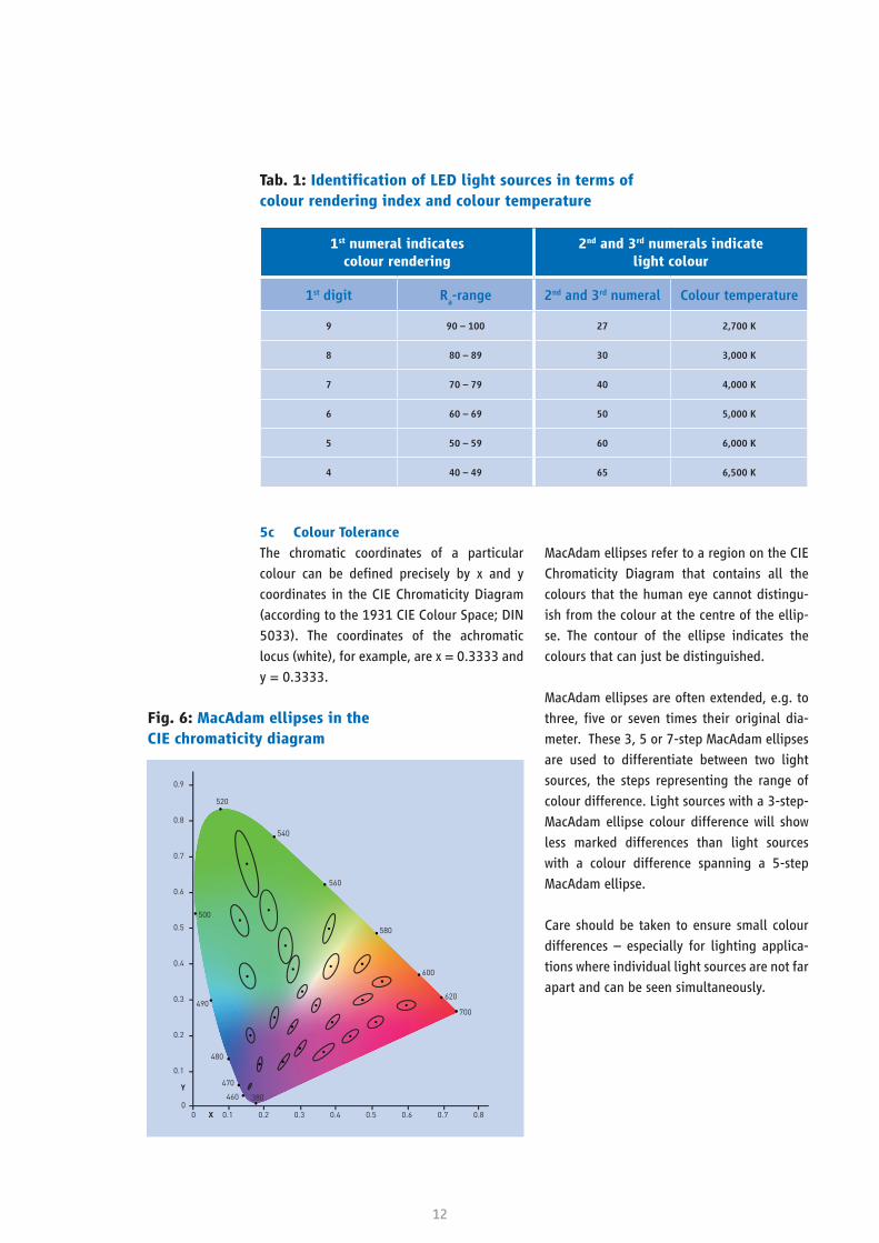
5c Colour Tolerance
The chromatic coordinates of a particular
colour can be defined precisely by x and y
coordinates in the CIE Chromaticity Diagram
(according to the 1931 CIE Colour Space; DIN
5033). The coordinates of the achromatic
locus (white), for example, are x = 0.3333 and
y = 0.3333.
MacAdam ellipses refer to a region on the CIE
Chromaticity Diagram that contains all the
colours that the human eye cannot distingu-
ish from the colour at the centre of the ellip-
se. The contour of the ellipse indicates the
colours that can just be distinguished.
MacAdam ellipses are often extended, e.g. to
three, five or seven times their original dia-
meter. These 3, 5 or 7-step MacAdam ellipses
are used to differentiate between two light
sources, the steps representing the range of
colour difference. Light sources with a 3-step-
MacAdam ellipse colour difference will show
less marked differences than light sources
with a colour difference spanning a 5-step
MacAdam ellipse.
Care should be taken to ensure small colour
differences – especially for lighting applica-
tions where individual light sources are not far
apart and can be seen simultaneously.
Fig. 6: MacAdam ellipses in the CIE chromaticity diagram
Tab. 1:IdentificationofLEDlightsourcesintermsof colour rendering index and colour temperature
1st numeral indicatescolour rendering
2nd and 3rd numerals indicate light colour
1st digit Ra-range 2nd and 3rd numeral Colour temperature
9 90 – 100 27 2,700 K
8 80 – 89 30 3,000 K
7 70 – 79 40 4,000 K
6 60 – 69 50 5,000 K
5 50 – 59 60 6,000 K
4 40 – 49 65 6,500 K

13
6 Rated Ambient Temperature for
Luminaires
Luminaire performance is influenced by ambi-
ent temperature.
The rated ambient temperature ta is the high-
est sustained temperature in which the lumi-
naire may be operated under normal operating
conditions (the value may be briefly exceeded
in operation by 10 K). Where ta = 25 °C, no
declaration is required on the luminaire; any
other rated ambient temperature value needs
to be declared (same rule applies to tq).
Temperature tq (quality) is a new parameter
indicating the highest rated ambient tempe-
rature permitted for a defined performance
(incl. life expectancy, lighting characteristics).
More than one tq value can be declared for
different performance characteristics.
7 Longevity Criteria for
LED Lighting Products
LED lifespans are not measured only to the
point of abrupt failure: up to a certain point,
the majority of LEDs do not actually fail at all;
their luminosity decreases over time (light de-
gradation). The lifespan of LEDs, modules and
luminaires is thus limited by the failure of the
relevant electronics or by the luminous flux
falling below a predefined minimum level.
Fig. 7 shows the two longevity criteria, abrupt
failure and light degradation, as defined in
current IEC draft standards:
In the case of LEDs, the two parameters essen-
tially depend on the permissible current and
the temperature inside the LED. LED manufac-
turers need to declare the relevant informati-
on so that module or luminaire manufactur-
ers can determine the life expectancy of their
products.
In the case of LED modules, light degrada-
tion and abrupt failure are also influenced
by the electrical interconnection of the LEDs,
the temperature at the tc or t
p point and other
characteristics of the module. Temperature
at the tc point (marking on housing or PCB)
is the maximum temperature permitted for
safety under normal operating conditions.
The tp point temperature is the temperature at
which the performance parameters are esti-
mated. The temperatures at tc and t
p points can
differ. Module manufacturers must therefore
make this information available to luminaire
manufacturers so that the latter may determi-
ne the life expectancy of their products.
This guide presents comparable quality crite-
ria that facilitate the assessment of technical
claims for LED luminaires. LED modules and
individual LEDs are not considered in greater
depth below.
Fig. 7: LED luminaire longevity criteria
LED luminaires
Light degradation
(LxB
y)
Abruptfailure(L
0C
z)

14
7a Rated Life (Lx) (useful life)
The light degradation of LED luminaires is in-
dicated by rated or useful life Lx, where lumi-
nous flux declines to a percentage x of initial
luminous flux.
Typical values of 'x'are 70 (L70
) or 80 percent
(L80
) for a given rated or useful life.
7.1 Longevity Criteria for LED Luminaires
In the case of LED luminaires, degradation
and abrupt failure depend additionally on the
electrical operating data of the LEDs or modu-
les in the luminaires, the ambient temperature
for the application and other characteristics of
the LED luminaires. Luminaire manufacturers
must declare the relevant information so that
the user or designer of a lighting installation
can determine when the installation requires
maintenance.
Fig. 8 shows the original state, degradation
and abrupt failure of a luminaire (terminology
from current draft standard):
Fig. 8: Failure state of a luminaire (original state, degradation and abrupt failure)
new
LED luminaire 100 %
gradual LxB
y
Light degradation ofLED luminaire
abrupt L0C
z
Abrupt failure of LED luminaire
or
15
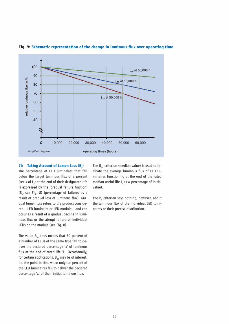
7b Taking Account of Lumen Loss (By)
The percentage of LED luminaires that fall
below the target luminous flux of x percent
(see x of Lx) at the end of their designated life
is expressed by the 'gradual failure fraction'
(By, see Fig. 8) (percentage of failures as a
result of gradual loss of luminous flux). Gra-
dual lumen loss refers to the product conside-
red – LED luminaire or LED module – and can
occur as a result of a gradual decline in lumi-
nous flux or the abrupt failure of individual
LEDs on the module (see Fig. 8).
The value B50
thus means that 50 percent of
a number of LEDs of the same type fail to de-
liver the declared percentage 'x' of luminous
flux at the end of rated life 'L'. Occasionally,
for certain applications, B10
may be of interest,
i.e. the point in time when only ten percent of
the LED luminaires fail to deliver the declared
percentage 'x' of their initial luminous flux.
The B50
criterion (median value) is used to in-
dicate the average luminous flux of LED lu-
minaires functioning at the end of the rated
median useful life Lx (x = percentage of initial
value).
The By criterion says nothing, however, about
the luminous flux of the individual LED lumi-
naires or their precise distribution.
Fig. 9:Schematicrepresentationofthechangeinluminousfluxoveroperatingtime
rela
tive
lum
inou
s fla
x in
%
operating times (hours)simplified diagram
at 60,000 h
at 50,000 h
at 50,000 h
10,000 20,000 30,000 40,000 50,000 60,000

16
7c Taking Account of
Abrupt Failures (Cz)
The percentage of LED luminaires that have
failed completely by the end of rated life 'Lx'is
expressed by 'Cz' (abrupt failure fraction, also
known as 'catastrophic failure rate', see Fig.
8). LED luminaires with only isolated LED fai-
lures and LED luminaires where only individu-
al LED modules fail among several do not fall
into the category of abrupt failure. The value
C3, for example, means that three percent of
a number of LED luminaires of the same type
failed abruptly within the rated life and thus
no longer deliver any light.
The failure of control gear or other luminaire
components is not considered by this crite-
rion. Studies and standardisation work have
been initiated to develop an approach that
includes such components.
8 ZVEI Recommendations
The ZVEI recommends that the parameters
described in this guide should be adopted and
declared as indicated.
There are two approaches to declaring the
lifespan of LED luminaires, both of which are
legitimate.
1 Based on IEC lifetime metrics:
• Declaration of useful life in hours to the
limit Lx B
y and, irrespective of that, decla-
ration of a second lifespan L0C
z for defi-
ned z values (e.g. 5 or 10 percent) iden-
tifying the point by which 'z' percent of
the luminaires have failed abruptly.
• Useful life 'Lx'where x = 80 percent (L80
)
and an ambient temperature of 25 °C
should be declared as typical variables.
• For the variable By, y = 50 percent (B
50) is
assumed unless otherwise stated.
2 From the viewpoint of lighting designers:
Declaration of a single defined useful life
in hours Lx B
y C
z (e.g. 50,000 hours) with
the declared luminous flux percentage 'x',
the gradual lumen loss 'y' (in percent –
declaration can be omitted where By =
B50) and the percentage 'z' of luminaires
that have failed abruptly (Cz) by the end of
their rated life 'Lx‘.
17
Maintenance factors are an important consi-
deration in the planning of lighting installa-
tions. For compliance with the DIN EN 12464
series of standards, for example, the planner
needs to establish and document how much
the luminous flux of a lighting installation will
decrease by a certain point in time and recom-
mend appropriate maintenance action.
The following maintenance factors are defi-
ned by CIE in the publications CIE 97 (Indoor
lighting) and CIE 154 (Outdoor lighting):
• MF: Maintenance Factor
• LLMF: Lamp Lumen Maintenance Factor
• LSF: Lamp Survival Factor
• LMF: Luminaire Maintenance Factor
• RMF: Room Maintenance Factor
• SMF: Surface Maintenance Factor
The maintenance factor MF of the lighting ins-
tallation is the product of the individual main-
tenance factors.
Indoor lighting:
MF = (LLMF × LSF) × LMF × RMF
Outdoor lighting:
MF = (LLMF × LSF) × LMF (× SMF)*
LLMF is obtained from manufacturers' light
degradation curves for the relevant observa-
tion period.
LSF is obtained from the number of LED light
sources that have failed abruptly over the
time (in hours) up to the observation point.
Lamp survival factor:
For lighting designs incorporating LED lumi-
naires, LLMF and LSF form a basis for rating
LED sources and can be determined for dif-
ferent luminous flux classes on the basis of
operating times (in hours). This method aligns
to the declaration of LLMF and LSF for conven-
tional lamps.
The relevant luminous flux class of an LED
luminaire is indicated by its useful life Lx
assuming a given 'reduction in luminous flux'.
'Lx'is expressed as follows: L
x–nn,nnn hours.
Examples:
L70
–50,000 hours; L80
–50,000 hours.
The following example shows how a manu-
facturer could present maintenance factors in
tabular form (lamp lumen maintenance factor
(LLWF) and lamp survival factor (LSF)):
V Notes on Lighting Planning
* SMF is used where appropriate, e.g. as surface maintenance factor of an illuminated surface or for pedestrian subways.
LSF(i h)
= 1 − Z(cz (i h)
)
100

18
In this example of tabular representation of
maintenance factors LLMF and LSF, the first
column shows the rated life of the LEDs (Lx –
ii,iii h). As a general rule, rated life is among
the specifications found in manufacturers'
product data sheets (examples: L90
– 25,000 h;
L80
– 50,000 h; L70
– 50,000 h).
Lamp lumen maintenance factors (LLMF) and
lamp survival factors (LSF) for the relevant
rated lifespans of LED luminaires are also
declared by luminaire manufacturers. Unless
otherwise stated, the values are specified for
an ambient temperature of 25 °C.
If this table is designed for B50
lumen loss, the
lamp lumen maintenance factor (LLMF) after
a rated life of ii,iii h reaches x/100, where x
is taken directly from the declared value Lx.
For other By rates of lumen loss, lamp lumen
maintenance factors (LLMF) differ.
The lamp survival factor (LSF), which expres-
ses the abrupt failure of an LED luminaire
(excluding control gear), may be negligible for
planning in many cases. Where a large num-
ber (> 100) of luminaires is considered, in-
dividual failures are statistically insignificant
although this may affect the appearance of
the installation. However, even where LSF = 1,
individual LED luminaires may have failed.
This approach is not appropriate for lumi-
naires with LED replacement lamps.
The advantage of tabular or graphic represen-
tation is that the planner can easily identify
the lumen loss at any specified point in time.
The method cannot be used for warranty state-
ments.
Rated life Operating time in 1,000 h
Parameters 1 5 10 15 20 25 30 35 40 45 50 55 60 65 70 75 80 85 90 95 100 …
L90
ii.iii h LLMF
LSF
L80
ii.iii h LLMF
LSF
L70
ii.iii h LLMF
LSF
L60
ii.iii h LLMF
LSF
L50
ii.iii h LLMF
LSF
Tab. 2: Maintenance factors of LED light sources and LED modules: LLMF and LSF
19
VI Appendix:Definitionsof Quality Criteria Performance Requirements
Term Definition Standard Remarks
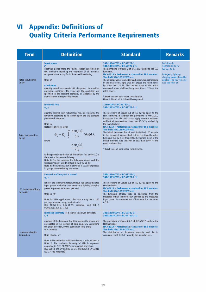
Rated input power (in W)
input powerPelectrical power from the mains supply consumed by the luminaire including the operation of all electrical components necessary for its intended functioning
Unit: W
rated valuequantity value for a characteristic of a product for specified operating conditions. The value and the conditions are specified in the relevant standard, or assigned by the manufacturer or responsible vendor
34D/1080/CDV > IEC 62722-1;34D/1093/CDV > IEC 62722-2-1:The provisions of Clause 7 of IEC 62717 apply to the LED luminaire.IEC 62717 – Performance standard for LED modules: The draft 34A/1659/CDV text:The initial power consumed by each individual LED module in the measured sample shall not exceed the rated power by more than 10 %. The sample mean of the initial consumed power shall not be greater than xx1) % of the rated power.
1) Exact value of xx is under consideration.Note 1: Note 2 of 1.1 should be regarded.
Definition in34D/1080/CDV forIEC 62722-1.
Emergency lighting charging power should be deleted – Ad-hoc remarks (see also item 3).
Rated luminous flux (in lm)
luminousfluxφ
V, φ
quantity derived from radiant flux, Fe, by evaluating the radiation according to its action upon the CIE standard photometric observer
Unit: lmNote: For photopic vision
where
is the spectral distribution of the radiant flux and V(λ ) is the spectral luminous efficiency.Note 2: For the values of Km (photopic vision) and K’m (scotopic vision), see IEC 60050-845, 845-01-56.Note 3: The luminous flux of LED dies is usually expressed in groups into which they are sorted.
1080/CDV > IEC 62722-1;34D/1093/CDV > IEC 62722-2-1:
The provisions of Clause 8.1 of IEC 62717 apply to the LED luminaire. In addition the provisions in Annex A.1, Paragraph 2 of IEC 61722-2-1 apply where a declared ambient air temperature other than 25 °C is advised by the manufacturer.IEC 62717 – Performance standard for LED modules: The draft 34A/1659/CDV text:The initial luminous flux of each individual LED module in the measured sample shall not be less than the rated luminous flux by more than 10%.The sample mean of the initial luminous flux shall not be less than xx1) % of the rated luminous flux.
1) Exact value of xx is under consideration.
LED luminaire efficacy (in lm/W)
Luminaireefficacy(ofasource)η
V, η
ratio of the luminaires total luminous flux versus its rated input power, excluding any emergency lighting charging power, expressed as lumens per watt
Unit: lm .W-1
Note:For LED applications, the source may be a LED package, module, lamp, luminaire etc.[IEC 60050-845, 845-01-55, modified] and [CIE S 017/E:2011 ILV, 17-730]
34D/1080/CDV > IEC 62722-1;34D/1093/CDV > IEC 62722-2-1:
The provisions of Clause 8.1 of IEC 62717 apply to the LED luminaire. IEC 62717 – Performance standard for LED modules: The draft 34A/1659/CDV text:The luminaire efficacy shall be calculated from the measured initial luminous flux divided by the measured input power. For measurement of luminous flux see Annex A.3.2.
Luminous intensity distribution
luminous intensity (of a source, in a given direction)IV; I
quotient of the luminous flux dFV leaving the source and propagated in the element of solid angle dΩ containing the given direction, by the element of solid angleIV = dFV/dΩ
Unit: cd = lm. sr-1
Note 1: The definition holds strictly only a point of source.Note 2: The luminous intensity of LED is expressed according to CIE 127:2007 measurement procedure.[IEC 60050-845:1987, 845-01-31] and [CIE S 017/E:2011 ILV, 17-739 modified]
34D/1080/CDV > IEC 62722-1;34D/1093/CDV > IEC 62722-2-1:
The provisions of Clause 8.2.3 of IEC 62717 apply to the LED luminaire. IEC 62717 – Performance standard for LED modules: The draft 34A/1659/CDV text:The distribution of luminous intensity shall be in accordance with that declared by the manufacturer.
Fv = K
m ∫
∞
0
d Fe (λ)
d λ V(λ)d λ
d Fe (λ)
d λ
20
Term Definition Standard Remarks
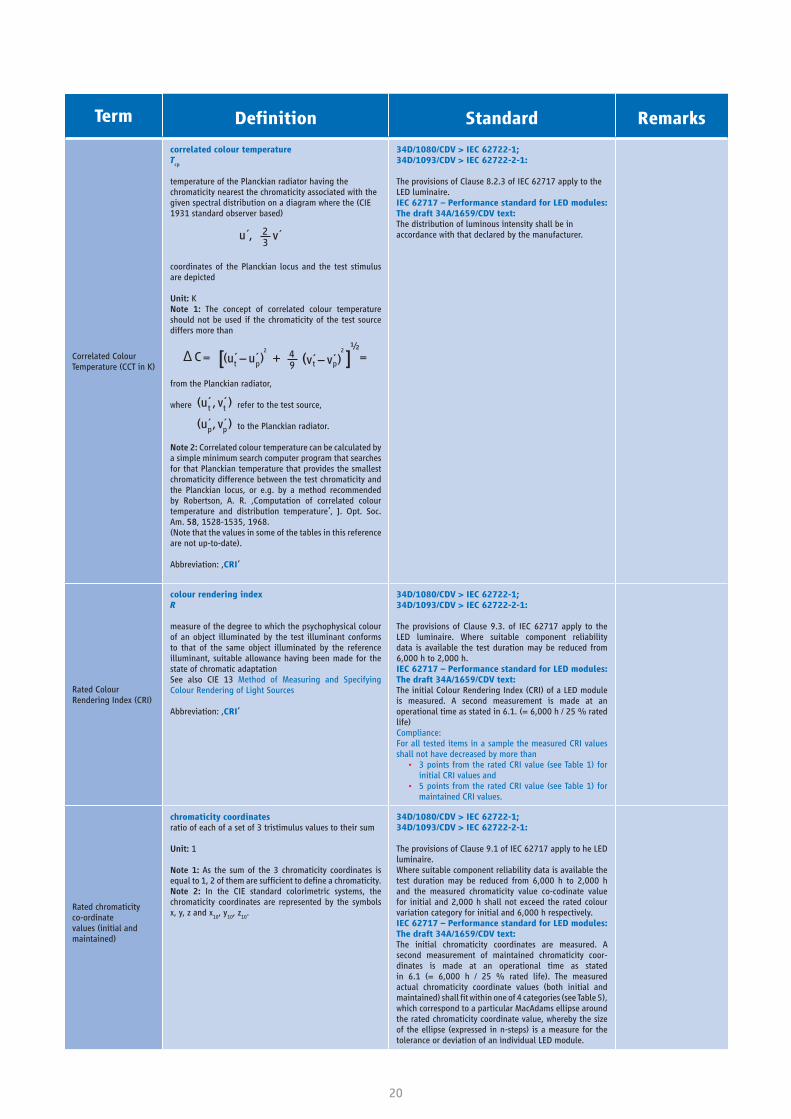
Correlated Colour Temperature (CCT in K)
correlated colour temperatureT
cp
temperature of the Planckian radiator having the chromaticity nearest the chromaticity associated with the given spectral distribution on a diagram where the (CIE 1931 standard observer based)
coordinates of the Planckian locus and the test stimulus are depicted
Unit: KNote 1: The concept of correlated colour temperature should not be used if the chromaticity of the test source differs more than
from the Planckian radiator,
where refer to the test source,
to the Planckian radiator.
Note 2: Correlated colour temperature can be calculated by a simple minimum search computer program that searches for that Planckian temperature that provides the smallest chromaticity difference between the test chromaticity and the Planckian locus, or e.g. by a method recommended by Robertson, A. R. ‚Computation of correlated colour temperature and distribution temperature‘, J. Opt. Soc. Am. 58, 1528-1535, 1968.(Note that the values in some of the tables in this reference are not up-to-date).
Abbreviation: ‚CRI‘
34D/1080/CDV > IEC 62722-1;34D/1093/CDV > IEC 62722-2-1:
The provisions of Clause 8.2.3 of IEC 62717 apply to the LED luminaire. IEC 62717 – Performance standard for LED modules: The draft 34A/1659/CDV text:The distribution of luminous intensity shall be in accordance with that declared by the manufacturer.
Rated Colour Rendering Index (CRI)
colour rendering index R
measure of the degree to which the psychophysical colour of an object illuminated by the test illuminant conforms to that of the same object illuminated by the reference illuminant, suitable allowance having been made for the state of chromatic adaptationSee also CIE 13 Method of Measuring and Specifying Colour Rendering of Light Sources
Abbreviation: ‚CRI‘
34D/1080/CDV > IEC 62722-1;34D/1093/CDV > IEC 62722-2-1:
The provisions of Clause 9.3. of IEC 62717 apply to the LED luminaire. Where suitable component reliability data is available the test duration may be reduced from 6,000 h to 2,000 h.IEC 62717 – Performance standard for LED modules: The draft 34A/1659/CDV text:The initial Colour Rendering Index (CRI) of a LED module is measured. A second measurement is made at an operational time as stated in 6.1. (= 6,000 h / 25 % rated life)Compliance:For all tested items in a sample the measured CRI values shall not have decreased by more than
• 3 points from the rated CRI value (see Table 1) for initial CRI values and
• 5 points from the rated CRI value (see Table 1) for maintained CRI values.
Rated chromaticityco-ordinate values (initial and maintained)
chromaticity coordinatesratio of each of a set of 3 tristimulus values to their sum
Unit: 1
Note 1: As the sum of the 3 chromaticity coordinates is equal to 1, 2 of them are sufficient to define a chromaticity.Note 2: In the CIE standard colorimetric systems, the chromaticity coordinates are represented by the symbols x, y, z and x
10, y
10, z
10.
34D/1080/CDV > IEC 62722-1;34D/1093/CDV > IEC 62722-2-1:
The provisions of Clause 9.1 of IEC 62717 apply to he LED luminaire. Where suitable component reliability data is available the test duration may be reduced from 6,000 h to 2,000 h and the measured chromaticity value co-codinate value for initial and 2,000 h shall not exceed the rated colour variation category for initial and 6,000 h respectively.IEC 62717 – Performance standard for LED modules: The draft 34A/1659/CDV text:The initial chromaticity coordinates are measured. A second measurement of maintained chromaticity coor- dinates is made at an operational time as stated in 6.1 (= 6,000 h / 25 % rated life). The measured actual chromaticity coordinate values (both initial and maintained) shall fit within one of 4 categories (see Table 5), which correspond to a particular MacAdams ellipse around the rated chromaticity coordinate value, whereby the size of the ellipse (expressed in n-steps) is a measure for the tolerance or deviation of an individual LED module.
u´, 23
v´
∆ C =t p(u´ − u´ )
2 ½+ 4
9 t p(v´ − v´ )2
=
t t(u´ , v´ )
p p(u´ , v´ )

21
Term Definition Standard Remarks
Maintained luminous flux
luminousfluxmaintenancefactorlumen maintenance factorf
LLM
ratio of the luminous flux emitted by the light source at a given time in its life to its initial luminous flux emitted, the light source being operated under specified conditions
Unit: This ratio generally expressed in percent.[IEC 60050-845, 845-07-65, modified]ratio of luminous flux of lamp at a given time in the life to the initial luminous flux
Note: Initial luminous flux of lamps is usually declared at 1 h for incandescent and 100 h for discharge lamps.
Abbreviation: ‚LLMF‘
34D/1080/CDV > IEC 62722-1;34D/1093/CDV > IEC 62722-2-1:
The provisions of Clause 10.2 of IEC 62717 apply to the LED luminaire. Where suitable component reliability data is available the test duration may be reduced from 6,000 h to 2,000 h
• the measured flux value at 2 000 h shall not be less than the rated maximum lumen maintenance value related to the rated life the measured lumen maintenance shall correspond with the 2,000 h lumen maintenance rated codes.
For all of the tested items in a sample, the measured values shall be of the same maintenance code as the provided value. All the LED modules in a sample shall pass the test.IEC 62717 – Performance standard for LED modules: The draft 34A/1659/CDV text:See subclause 10.2.
fLLM
is not used in IEC standards (at least LED module) as the shape of the lumen depreciation curve as function of time between LED modules varies among manufacturers and is depending on the specific LED technology used.Specified in IEC is ‘life’, which is the length of time during which a LED module provides more than claimed percentage x of the initial luminous flux, under standard conditions.This definition relates to a lamp: 34/175/CDV
Ambienttemperature (t
q) for a luminaire
temperature, rated ambient performance (rated ambient performance temperature)tq
highest ambient temperature around the luminaire related to a rated performance of the luminaire under normal operating conditions, both as declared by the manufacturer or responsible vendor
Unit: °C
Note 1: tq ≤ t
a For ta, see 1.2.25 of IEC 60598-1.
Note 2: For a given life time, the tq temperature is a fixed
value, not a variable.Note 3 There can be more than one t
q temperature,
depending on the life time claim.ambient temperature around the luminaire related to the performance of the luminaire
34D/1080/CDV > IEC 62722-1; 34D/1093/CDV > IEC 62722-2-1:
GeneralThe provisions of Subclause A.1 of IEC 62717 apply to the LED luminaire.Where a rated ambient performance temperature tq other than 25 °C is advised by the manufacturer a correction factor will need to be established to correct the measured luminous flux value at 25 °C to the luminous flux value at the declared ambient. This shall be done using relative photometry in a temperature controlled cabinet.
Definition from34/175/CDV.
Failure fraction (Fy),
corresponding to the rated life of the LED module in the luminaire
failure fraction at rated lifeF
y
percentage y of a number of LED products of the same type that at their rated life designates the percentage (fraction) of failures
Note 1: This failure fraction expresses the combined effect of all components of a module including mechanical, as far as the light output is concerned. The effect of the LED could either be less light than claimed or no light at all.Note 2: For LED modules normally a failure fraction of 10 % or/and 50 % are being applied, indicated as F
10
and/or F50
.
34D/1080/CDV > IEC 62722-1;34D/1093/CDV > IEC 62722-2-1:
Gradual failure fraction (By)
Percentage y of a number of LED modules of the same type that at their rated live designates the percentage (fraction) of failures. This failure fraction expresses only the gradual light output degradation.
Abrupt failure fraction (Cy)
Percentage y of a number of LED modules of the same type that at their rated live designates the percentage (fraction) of failures. This failure fraction expresses only the abrupt light output degradation.
The recommended metrics for specifying LED luminaire life time is explained in Annex C of IEC 62717 and differs from the pass/fail criterion of the life time test as in 10.2.
22
VII References
The appendix is taken from the following IEC
draft standards:
34D/1080/CDV
34D/1093/CDV
34A/1659/CDV
23
Notes
ZVEI - German Electrical andElectronic Manufacturers‘ AssociationLyoner Straße 960528 Frankfurt am Main, Germany
Phone: +49 69 6302-0Fax: +49 69 6302-317E-mail: [email protected] Ac
know
ledg
emen
ts fo
r ph
otog
raph
s Co
ver:
Kos
tia
Lom
zov,
Fot
olia
www.zvei.org