Embed Size (px)
Citation preview


Guide to Protective Coatings:Inspection and Maintenance
Tom N. Bortak
United States Department of the InteriorBureau of ReclamationTechnical Service Center
September 2002

Acknowledgments
Several Reclam ation em p loyees help ed
p rep are t h is g u id e, a n d th eir con tr ibu tio n is
gr ea tly ap p re ciate d . The se p eo p le ar e Ku rt F.
von Fay, m aterials engineer , w ho set u p
fu n d in g an d s h ow e d g re at p a tie n ce ov er th e
w ri ting interval ; D. Thom as (Tom ) John son,
m ater ials en gine er, for h is corr osion exp ertise
cont r ibu t ion ; Gregory J. Myers and Richard A.
Pep in, m ater ia ls engineer ing techn icians, for
th eir initial rev iew in ferretin g ou t obv iou s
er ror s; an d Rober t Ro od , ed ito r , for h is
nu m erous “I d on ' t u nd ers tand ” com m ents tha t
forced m e into w rit ing a clearer , m ore concise,
an d u n d erst an d able d ocu m en t.
A d eb t o f g ra tit ud e is expressed to N ACE
Inter n ation al, Society of Pro tective Co ating s,
an d U n iver sity of M issou r i-Rolla, C oa tin g
Ins t itu te for prov id ing a l l the courses and
references that m ad e this guid e p ossible.

Preface
In recent years , coat ing techn ology has
ch an ged d ra m at ically . Th e d riv in g for ce
behind the change h as been regu lat ions
affecting the en vironm ent an d p ersonn el
heal th and safety. For exam p le, regu lat ions
re la ted to du s t pa r t icles from abrasive b las ting ,
vo latile org an ic com p ou n d (VOC ) em ission s,
and hazard ous m ater ia ls su ch as lead ,
ch r o m a t e, a n d o t h er h e av y m e t a ls h av e
chan ged .
Before the late 1980s, coating m aterials w ere
m or e tole ra n t o f less th an op tim u m su rfa ce
p rep aratio n con d itio n s b eca u se p ain t
form u lation contained high VOC s to allow the
m ater ial to w et or p en etr ate st eel su rfaces. The
m o s t su cce ssfu l w e r e r ed le ad p r im e r s a n d
v in y l r es in s ; h o w e v e r , r eg u la tio n s h a v e
d isco u raged th e u se of t h ese m ate r ials . Pa in t
m an u factu rers reform u lated their coatings to
com p ly w ith ne w regu lation s. This has led to
th e d ev elop m en t o f a w id e v ar iety of h igh -tech
coatin g m ate r ials th at a re m u ch m or e sen sit ive
to su rface prep ara t ion and envi ronm enta l
ap p lica t ion p ract ices . The Fed era l H ighw ay
A d m in ist ra tio n h as e st im ated th at u p to 80
p ercent of a ll p rem atur e coat ing failu res on
br id ge s tr u ctu res ar e p ar tia lly or com p let ely
caused by d efic ient sur face p rep arat ion or
ap p lication p ractices . Several organizat ions
such as the Am erican Socie ty for Tes t ing an d
M aterials, N A CE Intern ational, and the
Society for Protective Co atings hav e issued
con sen su s st an d ar d s to m in im ize su rfa ce
p rep ara tion a n d ap p lication ina d equ acies.
Th is g u id e is n ot in ten d ed to be a ll
encomp assing; ra ther , it is in tend ed to be an
in t rodu ct ion to spec ific re fe rence standard s
an d test p ro ced u re s r ela ted to su rfa ce
p repara t ion , app lica t ion , tes ting , and
m aintenance of coat ings . Exp lanat ions and
p roced u res of r efe ren ce s ta n d ard s cited w ith in
this gu id e are abbreviated to d evelop a
w orking bas is. The user is encourag ed to read
re fe rence standard s and coa ting m anu a ls fo r a
m or e th or ou gh u n d er stan d in g . Th e g u id e
focu ses o n n ew con st ru ctio n coa tin gs, ex ist in g
infrast ruc ture coat ing m aintenance , and
galvanized coat ings of ferrou s substrates for
m etalw or k item s co ated in th e fie ld . In
general , th is gu id e follow s the Bu reau of
Reclam atio n ’s (Re clam atio n ) coa tin g gu id e
sp ecifications.

vii
Contents
Page
Chapte r I— In tro ducti on and Background . . . . . . . . . . . . . . . . . . . . . . . . . . . . . . . . . . . . . . . . . . . . . . . . 1
1. Standard s . . . . . . . . . . . . . . . . . . . . . . . . . . . . . . . . . . . . . . . . . . . . . . . . . . . . . . . . . . . . . . . . . . . . . . . 1
2. Coating References . . . . . . . . . . . . . . . . . . . . . . . . . . . . . . . . . . . . . . . . . . . . . . . . . . . . . . . . . . . . . . . 1
3. Term inology . . . . . . . . . . . . . . . . . . . . . . . . . . . . . . . . . . . . . . . . . . . . . . . . . . . . . . . . . . . . . . . . . . . . . 1
4. Corrosion . . . . . . . . . . . . . . . . . . . . . . . . . . . . . . . . . . . . . . . . . . . . . . . . . . . . . . . . . . . . . . . . . . . . . . . 1
5. Serv ice Exposure . . . . . . . . . . . . . . . . . . . . . . . . . . . . . . . . . . . . . . . . . . . . . . . . . . . . . . . . . . . . . . . . . 5
Chapter II—M aterials . . . . . . . . . . . . . . . . . . . . . . . . . . . . . . . . . . . . . . . . . . . . . . . . . . . . . . . . . . . . . . . . . . 5
6. Com pon ents o f Coa t ings . . . . . . . . . . . . . . . . . . . . . . . . . . . . . . . . . . . . . . . . . . . . . . . . . . . . . . . . . . . 5
7. Coating Typ es . . . . . . . . . . . . . . . . . . . . . . . . . . . . . . . . . . . . . . . . . . . . . . . . . . . . . . . . . . . . . . . . . . . . 7
8. Gener ic Coa t ings . . . . . . . . . . . . . . . . . . . . . . . . . . . . . . . . . . . . . . . . . . . . . . . . . . . . . . . . . . . . . . . . . 7
Chapter III—Speci f ications . . . . . . . . . . . . . . . . . . . . . . . . . . . . . . . . . . . . . . . . . . . . . . . . . . . . . . . . . . . . . 11
9. Con stru ction Sp ecification Institu te . . . . . . . . . . . . . . . . . . . . . . . . . . . . . . . . . . . . . . . . . . . . . . . . . 11
10. Reclam ation C oat ing Specifications . . . . . . . . . . . . . . . . . . . . . . . . . . . . . . . . . . . . . . . . . . . . . . . . . 11
11. Coating Tabu lations an d Categor ies . . . . . . . . . . . . . . . . . . . . . . . . . . . . . . . . . . . . . . . . . . . . . . . . . 12
12. M an u factu rer 's Prod u ct Data an d Ap p lication She ets . . . . . . . . . . . . . . . . . . . . . . . . . . . . . . . . . . 13
13. A d d e n d u m s a n d M o d ifica tio n s . . . . . . . . . . . . . . . . . . . . . . . . . . . . . . . . . . . . . . . . . . . . . . . . . . . . . 14
Chapter IV—Inspector's Role . . . . . . . . . . . . . . . . . . . . . . . . . . . . . . . . . . . . . . . . . . . . . . . . . . . . . . . . . . . . 15
14. Prim ary Resp onsibili ties . . . . . . . . . . . . . . . . . . . . . . . . . . . . . . . . . . . . . . . . . . . . . . . . . . . . . . . . . . . 15
15. Daily Respo nsibili ties . . . . . . . . . . . . . . . . . . . . . . . . . . . . . . . . . . . . . . . . . . . . . . . . . . . . . . . . . . . . . 15
16. M ater ia l Ap p roval . . . . . . . . . . . . . . . . . . . . . . . . . . . . . . . . . . . . . . . . . . . . . . . . . . . . . . . . . . . . . . . . 16
17. Docum entat ion . . . . . . . . . . . . . . . . . . . . . . . . . . . . . . . . . . . . . . . . . . . . . . . . . . . . . . . . . . . . . . . . . . . 16
18. In st ru m en ts , Ga u ges , an d Tools . . . . . . . . . . . . . . . . . . . . . . . . . . . . . . . . . . . . . . . . . . . . . . . . . . . . 17
19. Su bstrate Insp ect ion . . . . . . . . . . . . . . . . . . . . . . . . . . . . . . . . . . . . . . . . . . . . . . . . . . . . . . . . . . . . . . 17
20. Coating Insp ection Ch ecklist Sheet . . . . . . . . . . . . . . . . . . . . . . . . . . . . . . . . . . . . . . . . . . . . . . . . . . 17
21. Pre coa tin g Con fer en ce . . . . . . . . . . . . . . . . . . . . . . . . . . . . . . . . . . . . . . . . . . . . . . . . . . . . . . . . . . . . 17
Chap te r V—M aterial S to rage, Containers, an d Shelf Life . . . . . . . . . . . . . . . . . . . . . . . . . . . . . . . . . . . 19
22. Storage . . . . . . . . . . . . . . . . . . . . . . . . . . . . . . . . . . . . . . . . . . . . . . . . . . . . . . . . . . . . . . . . . . . . . . . . . . 19
23. Conta iners . . . . . . . . . . . . . . . . . . . . . . . . . . . . . . . . . . . . . . . . . . . . . . . . . . . . . . . . . . . . . . . . . . . . . . . 19
24. Shelf Life . . . . . . . . . . . . . . . . . . . . . . . . . . . . . . . . . . . . . . . . . . . . . . . . . . . . . . . . . . . . . . . . . . . . . . . . 19
Chapter VI—Surface Preparation . . . . . . . . . . . . . . . . . . . . . . . . . . . . . . . . . . . . . . . . . . . . . . . . . . . . . . . . 21
25. Su rface Conta m inan ts . . . . . . . . . . . . . . . . . . . . . . . . . . . . . . . . . . . . . . . . . . . . . . . . . . . . . . . . . . . . . 21
26. P re su r fa ce Tr ea tm e n t . . . . . . . . . . . . . . . . . . . . . . . . . . . . . . . . . . . . . . . . . . . . . . . . . . . . . . . . . . . . . 23
27. Abras ive Blas t Mater ia l . . . . . . . . . . . . . . . . . . . . . . . . . . . . . . . . . . . . . . . . . . . . . . . . . . . . . . . . . . . . 23
28. N ozz le Blast Pressu re . . . . . . . . . . . . . . . . . . . . . . . . . . . . . . . . . . . . . . . . . . . . . . . . . . . . . . . . . . . . . 24
29. Su rface Prep arat ion M ethod s . . . . . . . . . . . . . . . . . . . . . . . . . . . . . . . . . . . . . . . . . . . . . . . . . . . . . . . 25
30. Photographic Inspec tion Standard s . . . . . . . . . . . . . . . . . . . . . . . . . . . . . . . . . . . . . . . . . . . . . . . . . . 27
31. Alternat ive Su rface Prep arat ion M ethod s . . . . . . . . . . . . . . . . . . . . . . . . . . . . . . . . . . . . . . . . . . . . 30

viii
Page
Chapter VII—Environmental Condi tions . . . . . . . . . . . . . . . . . . . . . . . . . . . . . . . . . . . . . . . . . . . . . . . . . 33
32. Environm enta l Factors Affect ing Coa t ings . . . . . . . . . . . . . . . . . . . . . . . . . . . . . . . . . . . . . . . . . . . 33
Chapter VIII—Ap plication and Curing . . . . . . . . . . . . . . . . . . . . . . . . . . . . . . . . . . . . . . . . . . . . . . . . . . . 35
33. Ap p lication Tem p erature an d H u m id ity Restr ic tions . . . . . . . . . . . . . . . . . . . . . . . . . . . . . . . . . . 35
34. Coa t ing Layers . . . . . . . . . . . . . . . . . . . . . . . . . . . . . . . . . . . . . . . . . . . . . . . . . . . . . . . . . . . . . . . . . . . 35
35. M ixin g . . . . . . . . . . . . . . . . . . . . . . . . . . . . . . . . . . . . . . . . . . . . . . . . . . . . . . . . . . . . . . . . . . . . . . . . . . 36
36. Ap p lication M ethod . . . . . . . . . . . . . . . . . . . . . . . . . . . . . . . . . . . . . . . . . . . . . . . . . . . . . . . . . . . . . . 36
37. Ap pl ica t ion Technique . . . . . . . . . . . . . . . . . . . . . . . . . . . . . . . . . . . . . . . . . . . . . . . . . . . . . . . . . . . . 39
38. D ry in g , Reco atin g , an d Cu r in g . . . . . . . . . . . . . . . . . . . . . . . . . . . . . . . . . . . . . . . . . . . . . . . . . . . . . 39
Chapter IX—Field Inspection and Testing . . . . . . . . . . . . . . . . . . . . . . . . . . . . . . . . . . . . . . . . . . . . . . . . 41
39. Su rface Prep aration Tests . . . . . . . . . . . . . . . . . . . . . . . . . . . . . . . . . . . . . . . . . . . . . . . . . . . . . . . . . . 41
40. W et Film Th ickn ess . . . . . . . . . . . . . . . . . . . . . . . . . . . . . . . . . . . . . . . . . . . . . . . . . . . . . . . . . . . . . . . 42
41. H ard ened Painted Su rfaces . . . . . . . . . . . . . . . . . . . . . . . . . . . . . . . . . . . . . . . . . . . . . . . . . . . . . . . . 42
42. Destruct ive Test M ethod s . . . . . . . . . . . . . . . . . . . . . . . . . . . . . . . . . . . . . . . . . . . . . . . . . . . . . . . . . . 45
Chapter X—Maintenance Coatings . . . . . . . . . . . . . . . . . . . . . . . . . . . . . . . . . . . . . . . . . . . . . . . . . . . . . . . 47
43. Defini t ion . . . . . . . . . . . . . . . . . . . . . . . . . . . . . . . . . . . . . . . . . . . . . . . . . . . . . . . . . . . . . . . . . . . . . . . 47
44. Pu rp ose . . . . . . . . . . . . . . . . . . . . . . . . . . . . . . . . . . . . . . . . . . . . . . . . . . . . . . . . . . . . . . . . . . . . . . . . . 47
45. Risk Evalu at ion . . . . . . . . . . . . . . . . . . . . . . . . . . . . . . . . . . . . . . . . . . . . . . . . . . . . . . . . . . . . . . . . . . 47
46. Insp ect ion . . . . . . . . . . . . . . . . . . . . . . . . . . . . . . . . . . . . . . . . . . . . . . . . . . . . . . . . . . . . . . . . . . . . . . . 47
47. Toxic-Based Paints . . . . . . . . . . . . . . . . . . . . . . . . . . . . . . . . . . . . . . . . . . . . . . . . . . . . . . . . . . . . . . . . 49
48. W ork er Pr otection from Toxic-Based Paints . . . . . . . . . . . . . . . . . . . . . . . . . . . . . . . . . . . . . . . . . . 50
49. Lead Exposu re Levels by Remov al M ethod s . . . . . . . . . . . . . . . . . . . . . . . . . . . . . . . . . . . . . . . . . . 50
50. Correct ive A ction . . . . . . . . . . . . . . . . . . . . . . . . . . . . . . . . . . . . . . . . . . . . . . . . . . . . . . . . . . . . . . . . . 51
51. Mater ia l Se lect ion Factors . . . . . . . . . . . . . . . . . . . . . . . . . . . . . . . . . . . . . . . . . . . . . . . . . . . . . . . . . . 52
52. Sch ed u lin g . . . . . . . . . . . . . . . . . . . . . . . . . . . . . . . . . . . . . . . . . . . . . . . . . . . . . . . . . . . . . . . . . . . . . . 52
Chapter XI—Galvanizing . . . . . . . . . . . . . . . . . . . . . . . . . . . . . . . . . . . . . . . . . . . . . . . . . . . . . . . . . . . . . . . 53
53. Galvanizing M ethod s . . . . . . . . . . . . . . . . . . . . . . . . . . . . . . . . . . . . . . . . . . . . . . . . . . . . . . . . . . . . . 53
54. Z in c Cor ros ion an d Ser v ice Life . . . . . . . . . . . . . . . . . . . . . . . . . . . . . . . . . . . . . . . . . . . . . . . . . . . . . 54
55. Z in c C h em i ca l Re actio n s . . . . . . . . . . . . . . . . . . . . . . . . . . . . . . . . . . . . . . . . . . . . . . . . . . . . . . . . . . . 54
56. Con tam inan ts . . . . . . . . . . . . . . . . . . . . . . . . . . . . . . . . . . . . . . . . . . . . . . . . . . . . . . . . . . . . . . . . . . . . 54
57. Su rface Prep arat ion . . . . . . . . . . . . . . . . . . . . . . . . . . . . . . . . . . . . . . . . . . . . . . . . . . . . . . . . . . . . . . . 55
58. Coa t ings . . . . . . . . . . . . . . . . . . . . . . . . . . . . . . . . . . . . . . . . . . . . . . . . . . . . . . . . . . . . . . . . . . . . . . . . 57
Chapte r XII— Coati ng Failures . . . . . . . . . . . . . . . . . . . . . . . . . . . . . . . . . . . . . . . . . . . . . . . . . . . . . . . . . . . 59
59. M ater ia l Select ion . . . . . . . . . . . . . . . . . . . . . . . . . . . . . . . . . . . . . . . . . . . . . . . . . . . . . . . . . . . . . . . . . 59
60. Form u lat ion . . . . . . . . . . . . . . . . . . . . . . . . . . . . . . . . . . . . . . . . . . . . . . . . . . . . . . . . . . . . . . . . . . . . . 59
61. Ad hesion . . . . . . . . . . . . . . . . . . . . . . . . . . . . . . . . . . . . . . . . . . . . . . . . . . . . . . . . . . . . . . . . . . . . . . . . 61
62. Su bstrate . . . . . . . . . . . . . . . . . . . . . . . . . . . . . . . . . . . . . . . . . . . . . . . . . . . . . . . . . . . . . . . . . . . . . . . . 61
63. Ap p lication . . . . . . . . . . . . . . . . . . . . . . . . . . . . . . . . . . . . . . . . . . . . . . . . . . . . . . . . . . . . . . . . . . . . . . 62
64. Des ign . . . . . . . . . . . . . . . . . . . . . . . . . . . . . . . . . . . . . . . . . . . . . . . . . . . . . . . . . . . . . . . . . . . . . . . . . . 63
65. Exterior Forces . . . . . . . . . . . . . . . . . . . . . . . . . . . . . . . . . . . . . . . . . . . . . . . . . . . . . . . . . . . . . . . . . . . 67
Bi b li o grap h y . . . . . . . . . . . . . . . . . . . . . . . . . . . . . . . . . . . . . . . . . . . . . . . . . . . . . . . . . . . . . . . . . . . . . . . . . . 69
ix
Appendices
A Or gan izationa l Sou rces for Stan d ard s and References
B Read ing Sources
C Insp ection Ch ecklist
D Refer en ce Stan d ard s C ited in Gu id e
E Inspection Equ ipm ent
F Exam p le of Insp ection Daily Ch eck Sheet
G Proced u re fo r Det ect in g M ois tu re a n d O il in Com p ressed A ir (A STM D 4285)
H Procedu re for Detecting C hlorid es and Solu ble Sal ts in A brasives by Con d u ctivi ty Method
I Proced u res for Detecting Ch lorid e Ion in W ater
J Procedu res fo r Dete rmin ing Blas t Clean ing Ai r Pressure
K Determ ina t ion of Environm enta l Factors
L Proced u res for Detecting Ch lorid e Salts on P rep ared or Exist ing Su rfaces
M D eter m inin g Su rface P ro file of Blast-Clean ed Steel Usin g Rep lica Tap e
(N AC E RP0287 or ASTM D 4417, M ethod C)
N Proced u res for M ea su r in g W et Film Th ickn ess (A STM D 4414)
O W et Film Thickness Formu las and Exam p le Calcu lat ions
P Proced u res for D ry Film Th ickn ess G au ges (SSPC -PA 2) an d Exa m p le
Q Proced u res for D isco n tin u ity (H olid ay) Tes tin g (N A CE RP 0188)
R Proced u re fo r M ech an ical (P u lloff) A d h es ion Test in g (A STM D 4541; An n ex A 2)
S Proced u re fo r H yd rau lic A d h es ion Test in g (A STM D 4541; An n ex A 3)
T Procedu re fo r Measur ing Dry F ilm Thickness by Des truc t ive Means Wi th Tooke Gauge
(A STM D 4138)
U Procedu res for SSPC-VIS 2 (2000 Revis ion)
V Procedu re to Determ ine the Presence of So lub le Lead and Inso lub le Lead Ch rom ate in Coa t ings
W Procedu re to Determ ine the Presence of Chrom ate in Coa t ings
X D eter m in atio n of Tox ic M etals in H ard en ed Pain t
Figures
Figure Page
1 Com pon ents o f coa t ings . . . . . . . . . . . . . . . . . . . . . . . . . . . . . . . . . . . . . . . . . . . . . . . . . . . . . . . . . 5
Tables
Table Page
1 N u m ber of spot m easu rem ents based on total coated sur face area . . . . . . . . . . . . . . . . . . . 44
2 Typ ical and m axim u m lead exposu re levels in m icrogra m s per cubic meter
by rem oval m ethod . . . . . . . . . . . . . . . . . . . . . . . . . . . . . . . . . . . . . . . . . . . . . . . . . . . . . . . 51
3 Galvanizing m ethod s . . . . . . . . . . . . . . . . . . . . . . . . . . . . . . . . . . . . . . . . . . . . . . . . . . . . . . . . . . 53
4 Form ula tion-re la ted fa ilu res fo r o rgan ic coa t ings . . . . . . . . . . . . . . . . . . . . . . . . . . . . . . . . . . 60
5 Form ula tion-re la ted fa ilu res fo r inorgan ic coa t ings . . . . . . . . . . . . . . . . . . . . . . . . . . . . . . . . 61
6 Ad hesion-related fai lu res . . . . . . . . . . . . . . . . . . . . . . . . . . . . . . . . . . . . . . . . . . . . . . . . . . . . . . 62
7 Su bstrate-related fai lu res . . . . . . . . . . . . . . . . . . . . . . . . . . . . . . . . . . . . . . . . . . . . . . . . . . . . . . 63
8 Ap p lication-related failures . . . . . . . . . . . . . . . . . . . . . . . . . . . . . . . . . . . . . . . . . . . . . . . . . . . . 64
9 Design-related fai lu res . . . . . . . . . . . . . . . . . . . . . . . . . . . . . . . . . . . . . . . . . . . . . . . . . . . . . . . . 66
10 Failures related to exterior forces . . . . . . . . . . . . . . . . . . . . . . . . . . . . . . . . . . . . . . . . . . . . . . . . 67

1
Chapter I
Introduction and Background
Pro tective or ind u strial coating s are th e
p rimary m eans em p loyed by the Bu reau of
Reclam ation (Reclam ation) to control
corros ion . H yd rau lic st ru ctu res ar e t yp ically
cons t ruc ted w ith fe r rous meta ls and a re
sub ject to corrosion. Man y Reclam ation
s truc tures a re 50 years o ld , and some a re
app roach ing 100 years. These st ruc tures a re
exp ected to continu e fun ction ing into th e
foreseeab le fu tu re . P ro tect ive coa t ings
in flu en ce th e life, sa fety , op er at in g efficien cy ,
ap p ear an ce, an d econo m y of th ese stru ctu res.
A coa tin g 's e ffect iven ess d ep en d s o n se lect in g
coating m aterial that correctly m atches th e
in te n d ed se rv ice ex p osu re for th e m eta lw ork .
In the p as t, coat ing m ater ia l se lect ion w as
based on Fed eral, m ilitary, or Reclam ation
form u lations; how ev er, nea rly all these
form ula tions have been w ithd raw n. Tod ay ,
se lect ion i s based on service exp osure type and
th e r esu lts of a ccele ra ted p er for m an ce t es tin g
of com m ercially av ailable p rod u cts.
1. Standards.—Form erly, Reclam ation
p rovid ed narra t ive s tand ard s and d efini t ions
for specifying m ater ia ls, surface pr ep arat ion,
app lica t ion , and inspec tion . H ow ever ,
Reclam ation n ow ad op ts ind u strial stand ard s,
w here ap p licable . The follow ing or gan izat ions
(see app end ix A for add resses , te lep hon e
nu m bers, and w eb si tes) are referenced
thro u gh ou t this guid e:
• A m e rica n So cie ty fo r Te stin g an d
M ate r ials (A STM ).
• N AC E Intern ational (form erly called
N ational Associat ion of Corrosion
En gin ee rs) (N A CE).
• Socie ty fo r Pro tect ive Coa tings
(form erly called Steel Stru ctures
Pain tin g Cou n cil) (SSPC ).
2. Coating References.—Th e co atin g
insp ector is no t exp ected to h av e th e exp ertise
of a coa tin g ch em ical fo rm u lat or or a co atin g
engineer , bu t shou ld be reasonably fam iliar
w ith th e m ate r ials bein g ap p lied . Th is g u id e is
in ten d ed to p rov id ed th e m os t b asic
back gro u n d on gen er ic m at er ial ty p es , su rfa ce
p rep arat ion, app lication, and insp ect ion
m eth od s. The r ead er is en cou rag ed to p u rsu e
rela ted co atin g refe ren ce s lis ted in ap p en d ix B.
3. Terminology.—The w ord “coating ” is a
gen eric term an d inclu d es “p aint.” In th e
m ost general term s, a “coating” is protect ion
agains t corros ion , wh ereas a “pain t” m ay
hav e ad d it ional prop ert ies su ch as color or
u l t rav io le t screen ing p igm ents. The te rms
“coating ” an d “p aint” are u sed interchang e-
ably throu gh ou t this guid e.
O th er ter m s often u sed toge th er a re “ coating s”
an d “linin gs.” In g en eral, w he n d escribing the
interior su rfaces of p ipes or tan ks, the term
“linings” is u sed to iden t ify the inter ior
su rfaces an d “coatings” is u sed to iden tify th e
exter ior su r faces.
4. Corrosion.—The p r imary reason for
coating s teel is to preven t corrosion. Corrosion
of m eta ls is an e lect rochem ical react ion tha t
can be control led by interfer ing w ith on e or
m or e o f th e fo u r req u ired elem en ts of a
corros ion cell: (1) an od e (co rrod in g ar ea );
(2) cath od e (non corrod ing ar ea); (3) electrolyte
(w ater or m oisture in a tm osph ere, im m ersion,
or soil); an d (4) m etallic p ath (betw een tw o
d iffe ren t m eta ls o r w ith in th e sa m e m eta l).
Eliminate an y on e of the four requ ired
elem ents and the corrosion p rocess w ill s top.
The m ost com m on typ es of corrosion
encoun tered on Reclam ation ferrous
m etalw ork ar e:

Guide to Protective Coatings: Inspection and Maintenance
2
(a) Uniform Corrosion.—Corros ion tha t
occu rs m or e o r less u n ifor m ly an d resu lts in
ru st and m etal loss over th e m etal sur face.
(b) Galvanic Corrosion.— Corros ion tha t
occu rs on the m ore active m etal of tw o
d issim ilar m etals that are electr ical ly coup led
to geth er in th e sa m e electroly te (e.g ., w ate r ).
The m ore active m etal w ill corrod e.
(c) Crevice Corrosion.—Crevice corrosion
is a for m of lo calize d cor ros ion th at o ccu rs in
crevices w here the en vironm ent d iffers from
th e su r r ou n d in g bu lk en v ir on m e n t . Th e
d ifferent env ironm ents resul t in corrosion
because of d ifferences in concentrat ion
(e.g ., oxy gen , p H , an d fer r ic ion s). If th er e is
an oxygen concentrat ion d ifference, corrosion
w ill pr oceed at crev ices w h ere th ere is less
o xy g en th a n in th e en v ir on m e n t su r r ou n d in g
the crev ice. Crev ices are form ed w he n tw o
su rfa ces ar e in p ro xim ity to on e a n ot h er , su ch
as w hen tw o m etal surfaces are against one
anoth er , w hen a gasket is against a surface, or
w h en an g le iron s a re p laced back to back .
Cre vice corro sion can occu r u nd er d ep osits
(e .g ., barn acles , d ir t , grease, and s lim e) on a
m etal su rfa ce.
(d) Pitting corrosion.—A form of localized
corros ion w h er e t h e d ep th of p en et ra tio n is
grea ter than the d iam eter of the affected area .
(e) Cavitation corrosion.— The m etal loss
caused by the form ation an d collap se of vap or
bu bb les in a liqu id n ear a m etal su rface. The
app earance of cav ita tion is sim ila r to p i t ting ,
except tha t p i t ted areas are close ly spaced and
the su rface is consid erably rou gh ened .
(f) Erosion-corrosion.— The accelerated
m etal loss from an initial corro sion m echa n ism
associa ted w ith h igh-velocity flow s and
abrasion. Erosion-corrosion is cha racterized
by g roov es, gu llies, w aves, and rou nd ed
r id ges or va lleys and exhibit s a d irect ional
flow pa t te rn .
(g) Dealloying or Selective Leaching.—Th e
select ive rem oval of one of the e lem ents of an
alloy b y either p referen tial attack or com p lete
d isso lu t ion of the mat r ix , fo llow ed by
red ep osit of th e cath od ic con stitu en t. The
elem en t rem ove d is alw ays an od ic to the
m atrix. With d ealloying , there is n o m etal loss,
d im en sion ch an ges, cracks, or gr oov es;
how ever, the affected area m ay be ev iden t
because of a color cha ng e. The affected area
becom es lighter , p orous , and loses it s or ig ina l
m ech an ical p rop er tie s (i.e., it b eco m es br itt le
and loses tensile s t rength ). Tw o comm on
form s of d ealloying ar e:
Dezincification.— The select ive d issolu t ion
of zinc from brass al loys. It is recognized by a
color change (e .g ., from its or iginal yellow
brass co lor to a d i st inc tly red , copp ery
ap p ea ran ce).
Degraphitization.— Th e se le ct iv e
d issolu tion o f iron from som e cast iron s,
u su ally gra y cast iron s. It norm ally p roceeds
un iform ly inw ard f rom the sur face , leav ing a
p orou s m atr ix a lloy that is comp osed m ost ly of
carbon . Degraphi t iza t ion can be recognized by
a change from an or iginal s ilver-gray color to a
d ar k gra y . Th e a ffected m etal ca n be eas ily cu t
or p ierced w ith a k nife.
5. Service Exposure.—Coatings are sp ecified
by ser vice exposu re or th e env ironm en t the
coa t ing w ill be sub ject to . The fo llow ing a re
the basic serv ice exposu res d efined by
Reclam ation:
• A tm os p h er ic
N Ind oors
N Ou tdoors
• Bu r ia l
• Im m ersion
• Com p lete, p ar tia l, or flu ctu atin g
im m ersion cond ition s
• A tm osp he ric exp osu re su bject to
cond en sation , high h u m id ity, sp lash,
or spray
• The follow ing su bexposu re cond it ions
m ay ap p ly to any of the abov e:

Introduction and Background
3
N Direct su nl ight or UV: severa l
coatin gs, su ch as ep ox ies , w ill
d eteriorate by cha lking w hen
exp osed to su nlight.
N Ch em ical resistance: exposu res
m a y in clu d e acid ic o r a lk alin e
concen t ra t ions , ind us t r ia l smog,
acid ra in , sew age, o r sp ecific
chem icals.

5
Chapter II
Materials
Coating form u lat ion is generally based on
organ ic, inorgan ic, p olym er, an d co-p olym er
ch em ist ry . It is n ot th e in ten tio n of t h is
chap ter to d iscu ss coating chem istry b u t,
ra th er , to p rov id e a basic k n ow led ge o f coa tin g
com p onen ts and gen eric coating typ es
specified by Reclam ation.
6. Components of Coatings.—A ll or gan ic
co atin gs co n sis t of th ree basic co m p on en ts:
(1) so lven t, (2) res in , an d (3) p igm en t. N ot all
coating s contain solven t and p igm ented
com p on en ts . Th er e a re solv en t-fr ee (100
p ercent solids) coating s an d clear, p igm en t-
free coating s, bu t n ot resin -free coat ings.
Coa tin g ch em ical fo rm u lat or s co m m on ly
gro u p solvent, resin, and p igm en t com p on en ts
in to two genera l ca tegor ies. The fir s t ca tegory
com bin es t h e so lv en t a n d th e resin to geth er .
Th e solv en t p or tio n is ca lled th e “ v ola tile
veh icle,” an d the r esin p ortion is called th e
“n on volatile veh icle.” The com bination of the
so lven t a n d th e r es in , w h er e t h e r es in is
d issolved in the so lvent , is ca lled the “vehicle .”
The secon d category is the p igm en t. Pigm en ts
are ad d itives th at im p art sp ecific pr op erties to
the coating an d are su bd ivided into tw o
genera l ca tegor ies : (1) color and (2) iner t and
rein for ced . Figu re 1 illu st ra te s th e r ela tio n sh ip
of these com p on en ts.
W hen a coating is ap p lied , the solvent
ev ap or ate s d u r in g th e cu r in g p rocess, lea v in g
only the resin an d the p igm ent comp onen ts on
the subs t ra te . The remaining res in an d
p igm en ts ar e som et im es calle d th e “ coatin g
solid s ,” and they form the p rotect ive f ilm for
co rr osio n p r ote ctio n .
(a) Solvent.—Or gan ic solven ts are form u lated
in to coat ings to perform three essent ia l
fun ction s: (1) dissolve the r esin com p on en t;
(2) cont ro l evapora t ion for film form at ion; and
(3) red u ce the coating v iscosity for ease of
ap p licat ion . Solv en ts w ill also a ffect d ry film
ad h es ion an d d u rab ility coa tin g p rop er tie s. In
genera l, r esins tha t a re less so lub le wi ll r equ i re
either m ore solven ts or stron ger solven ts to
d issolve th e resin s.
The te rms “so lven ts” and “ th inners” a re
often used in terchangeab ly , bu t the re are
d ist in ct ion s w ith in an d betw een th e tw o te rm s.
The term “solvent” can im p ly tw o d ifferen t
u sa ges : (1) th e solv en t o r so lven t b len d s in
the coating form u lation a t p red eterm ined
So lv en t
(Volatile)
Resin
(No nv olatile)
Color
Pigm en ts
In e rt a n d
Reinforced
Veh icle P ig m e n t
C oa tin g
Figure 1.—Components of coatings.

Guide to Protective Coatings: Inspection and Maintenance
6
con cen tr a tio n lev els ; or (2) clean in g so lven ts in
st ron g con cen tr a tio n st ren g th for clea n in g
bru sh es, r olle rs, h ose s, a n d oth er eq u ip m en t.
The u sage of the ter m “th inn er” (a thin n er is a
solven t) is m ost often associated w ith the
coating ap p licator ad d ing a th inn er to a
coatin g con ta in er (n or m ally ab ou t 1 p in t
thin ne r to 1 gallon of coating ) to red u ce the
v isco sity for ea se of a p p licat ion . Ad d in g
thinn er to a coating in the f ield is often called
“fie ld th in n in g .”
Th e m an u fact u rer ’s p rod u ct d ata sh ee t w ill
specify a th inner and a m axim um am oun t tobe
u sed for each coating typ e. Use of a thinner
not recom m end ed by the m anu facturer can
cause nu m erou s app lication p roblems or
p rem atur e fai lu res such as separat ion of
comp onen ts , coagulat ion, too fast or too s low
d rying, changes in flow character is t ics, or
liftin g of p rev iou s co ats . Th e fo llow in g
com m on th inners ar e u sed w ith th e associated
gen eric coatin g ty p es:
Thinners Coat ings
M ineral sp irits O ils an d alkyd s
Ar om atics (ben zene,
xylol, tolu ole)
Co al tar ep oxies,
alkyd s, chlorina ted
rubbers
Keton es (MEK,
M IBK)
Vinyls, ep oxies,
u rethan es
A lcoh ols (isop rop yl) Ph en olics , inor gan ic
zin cs
W ater Acryl ics, som e
in or gan ic zin cs
Solvents prod u ce vapors tha t a re heavier than
air and w ill collect in tank b ottom s or confined
area s. Th e k eton es h av e th e lo w es t fla sh p oin t
of the or gan ic solven ts; how ever, any solven t
in the r ight com binat ion w ith a ir can crea te an
explosive com binat ion.
Fed er al, Stat e, co u n ty , city , an d loca l air
qu al ity control dis t r ic ts regulate the am ou nt of
v ola ti le organ ic solv en ts (VO C) in coatin gs. A s
the coating cures, VOC s evap orate into the
a tm os p h er e a n d rea ct w ith su n ligh t a n d air
p ollu tants to form ozone, a know n h u m an
h ea lth h azard . In resp on se , coa tin g
m an u fact u rer ’s h av e r efo rm u lat ed th eir
p rod u cts w ith low er solvent content to m eet
cu rre n t VO C r egu lations.
Reclam at ion specifica t ions requ i re the coa t ings
to m eet the VOC regu lat ions “in-the-can” or
“as-m an u fact u red ” befo re fie ld th in n in g . Field
thin nin g of a coating tha t w ill exceed the
regu la te d VO C m axim u m is n ot p erm itte d .
Reclam ation sp ecifies coating s based on the
cu rr en t En v iro n m en ta l Pr ot ect ion A gen cy
(EPA) VO C lim its.
(b) Resin.— The resin (frequ ently called
b in d er ) is th e film for m in g com p on en t o f a
coat ing . Res ins are typica lly a h igh m olecu lar
w eigh t solid po lymer tha t fo rm s la rge
rep eatin g m olecu les in th e cu red film . The
p rim ary p u rp ose of the resin is to w et the
p igm ent p art icles and bind the p igm ent
p art icles together a nd to the su bstrate (hen ce,
the term “bind er”). The resin im p arts m ost of
the coating p rop ert ies . The var ious typ es of
res ins form u la ted in a coat ing w ill d isp lay
d ist inct p rop ert ies. These p rop ert ies are:
• M e ch a n ism a n d t im e o f cu r in g
• Per form ance in se rv ice exposu re type
• Per form ance on subs t rate type
• Com pat ib ility wi th o ther coa t ings
• Flexibility an d tou gh n ess
• Ext er ior w ea th er in g
• Ad hesion
N o single res in can achieve a high d egree of
su cces s in m ee tin g th e a bov e co atin g
p rop ert ies w ith w ide v ariat ions associated
w ith ea ch p rop er ty . Th er efo re, g en er ic coa tin g
types a re generally classified by the p r im ary
resin ty p e u se d in th e coatin g form u la tion .
Typ ical resin s ar e acry lics, alky d s, and ep oxy
p olym ers.
(c) Pigment.— Pigm ents a re inso lub le and a re
the heavier so lid p or t ion of a coat ing tha t
ty p ica lly se tt les t o th e bott om of th e con ta in er .
P igm en ts ar e a d d itiv es to th e co atin g
form u lat ion th at im p art specific prop ert ies to

Materials
7
ach ieve t h e d esired film p ro p ert ies. Th e
fo llow ing p roper t ies a re accorded by
p igm ents, and a brief d escription is prov ided
fo r e ach .
Color.—N atu ral ea r th p igm en ts (kaolin
clay, m agn esiu m sil icate, calciu m carbona te)
p rov id e color stab ility from u ltrav iolet (UV)
su nlight d eterioration. N atu ral earth p igm en ts
are m or e U V s ta b le th an sy n th et ic or gan ic
p igm en ts.
Opacity.—Titan ium oxide h ides th e
subs t ra te or previous coat ing color and
pro tect s the b ind er from UV sunl igh t
d e te rio ra tio n .
Wet paint.—Silica and ta lc control
v isco sity , w et film lev elin g , an d se tt lin g bu t
prov ide lit tle h id ing (opac ity ) pow er .
Weather and moisture resistance.—
A lu m in u m lea fs an d m icaceo u s ir on ox id e
(M IO ) incre as e b ar rie r t h ickn ess an d for ce
m ois tu re to de tour a roun d these p late -like
ad d itive s.
Corrosion resistance.—Pigm en ts ad d ed to
inh ibi tive (pr im er) coatings im p ed e corrosion
of ferrou s substrates . Past form u lat ions
in clu d ed ch rom ate an d lead p igm en ts , bu t
they are seld om u sed tod ay because of
en vir on m en tal an d h ealth con cern s. The
fo llow ing chromate and lead p igm ents a re
rar ely u sed in cu rre n t coating form u lations:
• Red lead
• W hi te lead
• Basic lead silico-chrom ate
• Stron tium chrom ate
• Zinc chrom ate
Th e fo llow in g ar e a ccep ta b le a lte rn ativ e
inh ibitive p igm en ts:
• Bariu m m etabor ate
• Calciu m p ho sp ho silicate
• Z in c ox id e
• Zinc p ho sp ha te
• Zinc m olybd ate
• Zinc p ho sp ho silicate
Mildew resistance.—M ild e w c id e s p r ev en t
m ild ew grow th on the d ry f ilm coa t ing .
Skid or slip resistance.— A lu m in u m oxid e
o r m i n er al a gg re ga te is a d d e d in th e
form u lation or ap p lied to the w et film to
ach iev e n on slip su rface s. A lu m in u m ox id e is
the b etter choice because m ineral agg rega te
m a y b e cr u sh e d u n d e r w e ig h t, p r o vid in g
m o istu r e a cce ss to th e su b str ate , a n d
p rom ot ing fur ther coating d egrad at ion and
co rr osio n .
7. Coating Types.—The follow ing are th ree
ba sic typ es of coatings:
(a) Barrier.— A coating th at form s a
bar rier betw een the m etal sur face an d the
electroly te an d electr ica lly iso la te s t h e m eta l.
Exam p les are ep oxies an d coal tar ep oxies.
(b) Inhibitive.—P ig m e n t in a co atin g
p r im er tha t is slight ly so lu ble in w ater tha t
for m s a ch em ical in h ib ito r an d effectiv ely
in ter feres w ith the e lect ro ly te . Exam p les are
red lead and chrom ate p rim ers (no long er
accep ta b le).
(c) Galvanic.—Zinc-r ich p r im er coa t ings
tha t p rov ide g alvan ic or catho d ic p rotection to
fer ro u s m etal (z in c sacrifices itse lf to p ro tect
the fe r rous meta l). Ga lvan ic coa t ings a re
effectiv e o n ly if ap p lied d irect ly to bare m etal.
8. Generic Coatings.—Th e fo llow in g gen er ic
coatin gs a n d gen er al d escr ip tio n s a re t yp ically
specified by Reclam ation:
(a) Acrylics.— In w ate r -bor n e a cry lic
coating s, the r esin is d ispersed in w ater to
for m a w at er em u lsion . W at er -bo rn e a cry lics
are sp ecified for atm osp h eric expo su res as a
p r im er or top coat and have excellent color and
gloss retention. Acrylics cure by coalescence.
(b) Alkyds.—Alkyd s are norm ally na tu ra l
oils (soya, tu ng , styrenate) that h ave been
chem ically m od ified to im p rove cu re rate,
ch em ical r es ista n ce, an d h ar d n ess. Ph en olic-
m od ified a lkyd s are specified as a pr imer , and
silicone alkyd s are specified as the topcoat for
atm osph eric service exposu res . They are not

Guide to Protective Coatings: Inspection and Maintenance
8
su i tab le fo r a lka line (concre te o r m asonry)
su rface s o r en v iron m en ts . A lkyd s cu re b y air
oxid ation of d ry ing o ils.
(c) Bituminous.—Bitum inou s coa t ings a re
h ea v y-bo d ied m at er ials a p p lied w ith a cu tb ack
solven t. They h ave go od m oistu re barr ier
re sist an ce a n d fair to goo d ch em ical r es ista n ce
bu t are not res is tant to so lvents . Com m ercia l
bitum inou s pr od u cts are sp ecified on a l im ited
basis by Reclam ation for protect ion of
alum inu m su rfaces in contact w ith
cem en tit iou s m ate r ial o r stee l an d cop p er cab le
w eld connec tions . Bitum inou s coa t ings cure
b y so lv en t e va p o ra tio n .
(d) Epoxy, Amine.— Am ine epoxies a re
tw o-com p onen t coatings that are catalyzed
(hard en ed ) by an am ine cur ing ag en t to
p rod u ce a hard , t ight ly bond ed , chem ical
resis ta n t (a lkali, acid , an d so lv en t) p rod u ct , bu t
t h ey a re m o is tu r e a n d t em p e r a tu r e se n sit iv e
d u ring ap p lication. They are sp ecified for
bur ia l and im m ersion se rv ice exposu res, bu t
th ey w ill fa d e an d ch alk in d irect su n lig h t.
Am ine ep oxies cu re by chem ical reaction.
(e) Epoxy, Polyamide.— Polyam ide ep oxies
are tw o com p onen t coatings that are catalyzed
by a p oly am id e cu rin g ag en t to p ro d u ce
su p erior r esistance to w ater an d salt solution s,
bu t they do n ot provide the chem ical
resistance of the am ine ep oxy. Polyam ides
h av e a grea te r flexib ility th an th e a m in e
epoxies . They are sp ecified for bu r ia l and
im m er sio n se rv ice e xp os u res , bu t th ey w ill
fad e a n d ch alk in d irect su n ligh t. Poly am id e
ep oxies cu re by chem ical reaction.
(f) Epoxy, Coal Tar.— Coal t a r epoxies a re
ge n era lly a n am ine o r p olya m id e ep oxy
m od ified w ith coal tar pi tch r esin to p rod u ce a
high-bu ild film tha t has good chem ical
resistance and excellent w ater resistance. They
have a tend ency to becom e br it t le w ith age and
d ela m in ate betw ee n coa ts or ben ea th rep air
p atches . They are sp ecified for bu r ia l and
im m er sio n se rv ice e xp os u res , bu t th ey w ill
fad e and chalk in d irect su nl ight . Coal ta r
ep oxies cu re by chem ical reaction.
(g) Epoxy, Fusion-Bonded.— Fusion-
bon d ed ep oxies (com m only called p ow d er
coating s) are com p lete coating s in p ow d er
form . The re a re tw o ap p lication m eth od s,
flu idized -bed an d electrostatic. In the
flu id ized -bed m ethod , the meta l it ems a re
p r eh e ate d to a fu s io n te m p e r atu r e a n d
im m er sed in th e p ow d er -ep ox y so lu tio n . In
the electrostat ic meth od , the ep oxy p ow d er
p ar t icles are charged w ith h igh vol tage , and
the meta l it em i s then sprayed . Afte r spray ing ,
the i tem is placed in an oven to cure a t abou t
350 to 650 d egrees Fahren hei t (F). Fusion-
bond ed epoxies are specified for bu r ia l and
im m er sio n se rv ice e xp os u res , bu t th ey w ill
fad e and cha lk in d irect sun ligh t and a re
bri t t le . A n ew m aterial is fu sion-bon d ed
nylon. This mater ia l is sup erior to the fu sion-
bon d ed ep oxy an d w ill be incorp orated into
Reclam atio n 's sp ecifica tio n . Po w d er coa tin gs
cu re b y fu sio n (h ea t).
(h) Inorganic Zinc Primers.— In or gan ic
z incs a re p r im ers tha t incorpora te a h igh
load ing (p ou nd s per gal lon) of m etallic z inc for
p igm enta t ion (hence, the term “zinc-r ich”) and
are e ith er so lven t o r w ate r based . Dep en d in g
on th e solv en t a n d res in s u sed , th e co atin g
m ay be a zinc-rich ep oxy o r u reth an e. Th ese
coating s are exclusively p rim ers because th ey
p rovid e galvan ic or cathod ic p rotection to steel
sub strate. Inorg anic z incs are sp ecified for
atm osp h eric and im m ersion serv ice exp osu res,
bu t th ey can be top coated to ex ten d th eir
service life . Su itable topcoat m ater ia l select ion
is requ ired to p rev en t ou t-gassing from the
in or gan ic zin c th at p rod u ces sm all p in h ole s in
th e top coat. Reclam atio n sp ecifie s in or gan ic
zinc coatings only to fraying su rfaces or heated
tre ated m etalw or k (A STM A 325 or A STM
A 490). Ap p lica t ion requ ires sp ecia l sk ills and
kn ow ledge. Inor gan ic zincs cure by either
reaction to w ater (solven t redu cible) or
rea ctio n to car bon d iox id e (w ate r red u cib le).
(i) Organic Zinc Primers.— O rg an ic zin cs
are p r im er s th at in corp or ate a h igh loa d in g
(p ou nd s per gal lon) of m etallic z inc for
p igm en tation w ith a w ide v ariety of solven ts
a n d r esin s. D ep e n d in g on th e so lv en t a n d

Materials
9
re sin s u sed , th e co at in g m ay be a zin c-rich
alkyd , d rying oil , ep oxy, or m oistu re-cu red
u reth an e. Th ese co atin gs a re e xclu siv ely
p r im er s b eca u se th ey p rov id e g alvan ic
p rotection to steel substr ate or th ey ar e u sed to
rep air da m aged galvan ized coatings on steel
sub strates . Org anic z incs are sp ecified for
at m osp h er ic, bu ria l, an d im m er sion serv ice
exp osu res bu t are n orm ally top coated to
ex ten d th e ser v ice life of th e co atin g . Su ita b le
top coat m aterial selection is requ ired to
p rev en t o u t-gass in g from th e organ ic z in c.
O u t-gassing p rod u ces sm all p inh oles in th e
top coat . The w ay org an ic zincs cure d ep end s
on th e coating typ e.
(j) Polyurethane.—Technica lly ,
p olyu rethan e is a subclass of u rethan e. A tw o-
com pon ent po lyure thane is crea ted by
chem ically com bining a p olyisoyanate and a
p olyol to p rod u ce an isocyan ate that has a tw o-
m o d e cu r e m e ch a n ism o f so lv en t e va p o ra tio n
an d chem ical reaction. Reclam ation specifies
p olyu reth an es fo r to p coatin g com p atib le (i.e .,
sa m e m an u fact u rer ) am in e a n d p oly am id e
epoxies to p ro tect agains t d i rect sun ligh t
or U V a n d to p rov id e sp ecific co lors.
Poly u reth an es ar e sp ecified for at m os p h er ic
an d p ar tia l or flu ctu at in g im m er sion serv ice
exp osu res.
(k) Urethane.—Urethane coa t ings vary
w id ely in for m u lat ion s for sp ecific ser v ice
en v iron m en ts an d ap p lica tion requ irem en ts .
Reclam ation sp ecifies sing le-com p on en t,
m oisture-cu red u rethan es. They cure f rom
m oistu re in the atm osp her e and can be ap p lied
to d am p sur faces that d o no t hav e free
m ois tu re p resen t . These u re thanes a re
form u la ted w ith var ious p igm enta t ions and
are sp ecified in sev er al com bin atio n s to s u it
th e inten d ed serv ice exp osu re. These
u reth an es ar e sp ecified for at m os p h er ic, bu r ial,
an d im m ersion exp osu res.

11
Chapter III
Specifications
Reclam ation constru ction jobs are ad vert ised
to con t ractors to per form the requ i red w ork ,
an d con tr acto r se lect ion is m ad e b y a b id
p rocess . The m ost com m on bid typ es are low
p r ice , n egotia te d , fixe d cost , an d so le so u rce .
O n ce Recla m ation accep ts a con tr actor ’s b id , a
contra ct exists betw een Reclam ation an d the
contractor. The contract is often called a
sp ecification. The sp ecification can be d efined
as a w ri tten, d etailed , techn ical d escr ipt ion of
w o rk to be p er fo rm e d , d e scr ib in g th e
m ate r ia ls, q u an tities, a n d m od e of
co n str u ctio n .
Sp ecifications are d ivided into m any d ivis ions
to descr ibe the var ious job requi remen ts and
m a y in clu d e ge n er al jo b d e scr ip t io n ,
su bm ittals, p re-existin g con d ition s,
envi ronm enta l requi remen ts , and techn ica l
arch itectu ral, civil, e lect r ical, m ech an ical,
coatin g , an d ca th od ic p rote ct ion d iscip lin es.
Each d iv ision i s somet im es ca lled a techn ica l
p a r ag ra p h o r se ctio n .
9. Construction Specification Institute.—Reclam atio n h as ch an ged fro m a n arra tiv e
p aragrap h form at to the Con struct ion
Sp ecification Inst itute (CSI) form at for
sp ecifications. CSI form at style is m ore concise
an d u ses im p er at ive lan gu ag e. Refe re n ce
stand ard s are specified to descr ibe qu al ity of
m ater ia ls , w ork m od e, test m ethod s , and
accep tance criteria tha t are a recognized
ind u stry pract ice, thu s redu cing th e need for
len g th y ver b iag e. Th e m os t com m on re fer en ce
s tand ards u sed in the coa t ings ind us t ry a re
ASTM, N ACE, and SSPC.
CSI specifications are d ivided into 16 d ivis ions
for a l l the bu ild ing t rad es , and each d ivis ion
m ay be fu r th er d iv id ed in to sp ecia lity se ct ion s.
F in ishes are Division 9 , and p ain t and
p ro tectiv e co at in gs a re Section 09900. Each
sectio n is su bd iv id ed in to th e fo llow in g basic
p arts:
Part 1 : Genera l .—Includ es cost,
referen ces, su bm itta ls, q u ality assu ran ce ,
d elive ry , stora ge, ha n d lin g, an d restr ictions.
Part 2: Prod uct .—Includ es requ irem en ts
for m aterials to be u sed
Part 3 : Execut ion.—Inclu d es m od e of
const ruct ion , tes t m ethod s , acceptance cr ite r ia ,
and repai r
10. Reclamation Coating Specifications.—The Techn ical Service Cen ter (TSC) in D env er
m ain ta in s C SI gu id elin e coatin g sp ecification s.
The g u ideline coating sp ecification s are th e
bas is for specific p roject requi rem ents and are
base d on h ist or ica l Re cla m ation st ru ctu res.
Th e g u id elin e sp ecifica tio n s co n ta in
instru ction al notes an d footnotes to aid the
sp ecification w riter in p rep aring the
sp ecificat ion s to m ee t sp ecific p ro ject
req u irem en ts . Th e g u id elin e co atin g
sp ecification s are av ailab le on Reclam ation ’s
in tr an et w ebsit e: <h tt p :/ / in tr a .u sb r .gov >.
Reclam ation u ses the follow ing sp eciality
sections for coating s and haz ard ou s based -
p aints:
Sect io n 09902.—C oa tin gs fo r n ew m etallic
su bst ra te s th at in clu d e: stee l, cas t o r d u ctile
iron; galvan ized , a lu m inu m ; brass; bron ze; or
copp er
Sect io n 09908.—M aintenance coat ings for
p revious ly coated m eta llic subs t ra tes tha t
inclu d e: s teel, cast or d u ctile iron; galvan ized,
alum inu m ; brass; bron ze; or copp er
Sect io n 09980.—Coat ings for concre te and
m asonr y su bstrates
Sect io n 13283.— H a n d lin g an d d isp o sin g
of p ain t con ta in in g h eav y m eta ls ( i.e .,
ch rom ate , lead , et c. . .)

Guide to Protective Coatings: Inspection and Maintenance
12
(a) Part 1: General.—P ar t 1 in clu d e s th e
follow ing gen eral outl ine:
• Cost prov is ions for e ither lum p sum or
bid i tem
• References fo r ind us t r ia l s tand ards
u sed in the sp ecification section
• Su bm ittals are req u ired to en su re th e
contractor is sup p lying the sp ecified
m ate r ials . Th e fo llow in g su bm itta ls
are e ssen tia l:
" M a n u fa ctu r er ’s p r o d u ct d a ta an d
ap p lication sheets
" M anu factu rer’s cer t ification of
com p lian ce, s ta tin g th at m ate r ials
w er e m an u factu re d in acco rd an ce
w ith qu ality assu ran ce and qu ality
p ro gra m s to in clu d e b at ch
nu m bers , qu ant i ty , and color
" P u r ch a se or d e rs, e n su r in g th a t th e
contractor u sing ap p roved
m at er ials t o in clu d e b at ch
nu m bers , qu ant i ty , and color
• Q u ality as su ra n ce
• D eliv er y , sto rage, a n d h an d lin g
• En v iro n m en ta l re str iction s for su rfa ce
p rep arat ion an d ap p lication
(b) Part 2: Products.— P ar t 2 in clu d e s th e
follow ing m aterial requ irem ents ou tline:
• Ab rasives
• M IO
• Coat ings
(c) Part 3: Execution.— P ar t 3 in clu d e s th e
follow ing ou tline requ irem en ts to com p lete
w ork :
• Prot ect ion an d rep air of e xist in g
su rfaces
• Em bed d ed m etalw ork in concrete
• Su rface pr ep arat ion m ethod s
• A p p lica tio n eq u ip m e n t
• Coa ting ap p lication requ irem en ts
• In sp ect ion m eth od s an d acce p ta n ce
cr ite r ia
• Rep air of d am aged an d n on accep ta b le
coated areas
• Coating tab u lat ions an d categories (see
follow ing sect ion)
• Colo r sch ed u le
11. Coating Tabulations and Categories.—The form at of the coat ing tabu la t ions and
ca tegor ies in the CSI specifica t ions w ill be
sim ila r to th e old n arra tiv e p aragrap h form at.
The coa t ing tabu la tions and ca tegor ies change
ov er tim e becau se of low er VO C r egu lations,
lead- and chrom ate-free requirem ents, new
coating techn ology d evelopm ents, and other
factors. The follow ing section s d escribe th e
tab u lations an d categor ies.
(a) Coating Tabulations.— Th e co atin g
tabu lat ions are based on Reclam ation’s
h i sto r ica l exper ience w ith coa t ing m etalw ork
item s, se rv ice e xp os u re, a n d m ate r ials u sed in
d a m s a n d w a t er co n v ey an ce p ro je cts. Th e
tabu lation s are in th e follow ing tab le form at:
• I tem s to be coated are iden tif ied .
• Coa ting m aterials are id en tified in the
first colum n b y an alph an u m eric label
for a man ufacture r ’s b rand nam e or a
Fed eral/ m ilitary sp ecification n u m ber .
Sev er al eq u ivalen t co atin g m ate r ials
m ay be lis ted w ith in the sam e m ater ia l
o p tio n n u m b e r. M o r e th a n on e
coating m aterial op tion m ay be l is ted
in the tabu lation . For sm all jobs, the
color m ay be sp ecified in th is co lu m n .
• N u m ber of coats (p rim er,
inter m ed iate, an d top coat), thickn ess

Specifications
13
of e ach ap p lied coa t, an d to ta l d ry film
thickn ess (DFT) of the coating system
are id en tified in th e seco n d colu m n .
• Sur face p repara t ion m ethods a re
id en tified by let te r or alp h an u m er ic
labe l in the th ird co lum n and a re
d efined in th e execut ion p ar t for
surface pr ep arat ion.
• Ins t ruc t ional notes , if specified , a re
located at either tab le front or en d .
(b) Coating Categories.—Th e co atin g
categories spe cify, by a lph an u m eric labels, the
m anu factu rer’s brand nam e or the Fed eral or
m ilita ry sp ecifica tio n n u m ber of t h e co atin g
m a t er ia l liste d in th e ta bu la tio n s. Th e
categories are su bd ivided accord ing to th e
follow ing th ree esse n tial ch ara cteristics:
Compos i t ion.—Lis t the gener ic chem ical
coat ing n am e
Phy si cal cha ract eris t ics .—W eight p er
gal lon, VOC content , m inim u m ap p lication
tem p er atu re, cu r in g tim es at sp ecific
tem p er at u re an d h u m id ity , etc.
Performance requi rement s .— A ccelerated
A STM te st in g an d accep ta n ce cr ite r ia
12. Manufacturer's Product Data and
Application Sheets.—Reclam ation
sp ecification s requ ire the su bm ittal of the
coating m an u factu rer’s p rod u ct da ta
(somet imes ca lled techn ica l d a ta) and
ap p licat ion sh ee ts . Th ese sh ee ts sp ecify
the m anu facturer ’s ins t ruc t ions and
reco m m en d atio n s. Th e m an u fact u rer 's
ins t ruc t ions and recom m end at ions have
becom e sp ecification requ irem en ts, u nless the
sp ecificat ion s a re m or e r es tr ictiv e. P ro d u ct
d ata and ap p lication sheets shou ld be kep t for
fu tu re refe rence to ver ify the mate r ia l type
ap p lied . The pr od u ct d ata and ap p lication
sheets vary in content an d form at from
m anu factu rer to m anu factu re . Som e
m a n u f actu r er s co m b in e p ro d u ct d a ta an d
ap p lication into on e sheet. H ow ever , the
sheets p rov ide u seful inform ation for th e
sp ecific m ate r ial.
(a) Product Data Sheet.— The fo llow ing a re
the m ost com m on item s on th e p rod u ct da ta
sh eets:
• Gener ic chem ical coat ing n am e
(acrylic, alkyd , ep oxy, p olyur ethan e)
• Typ ical u ses, such as on br id ges,
p ipes , o r w ater t anks
• Serv ice ex p osu re for at m osp h er ic,
bu r ial, im m er sio n (fre sh w ate r or sa lt
w at er ), an d ch em ical r es ista n ce
• Color an d gloss availabili ty
• Ph ysica l or tech n ical p ro p er ties , su ch
as weigh t per ga llon , so lid s by
volu m e, VOC content , pigm ent
ad d itiv es , flash p oin t, an d serv ice
tem p er at u re re sist an ce
• Recom m en d ed d ry or w et film
th ickn ess
• Theoret ical coverage rate per gal lon
• M ix r a tio (if m u ltico m p on en t system ),
p ot life, an d in d u ctio n or sw ea t-in tim e
(elap sed tim e interv al to allow the
chem ical reaction to begin for
m ul t icom pon ent mate r ia ls before
a p p lica tio n )
• D ry , re coat, cu r in g , an d fu ll cu re t im e
p eriod s at tem p eratu re an d hu m idity
ran ges
• Perform an ce test results (accelerated
ASTM tes ts tha t m ay or may n o t be
listed )
• Shelf life
• Safety precau t ions
• Sh ip p in g d ata
• W arr an ty an d lim itation s of liabili ty
(b) Application Sheet.—The follow ing ar e the
m ost com m on item s on th e ap p lication sheet:

Guide to Protective Coatings: Inspection and Maintenance
14
• Su bst ra te ty p es th at a re co m p atib le
w ith th e coatin g m ate r ia l (e .g .,
a lu m in u m , con cret e, g alvan ize d , ste el,
cast iron , or existin g coated su rfaces)
• Su rface p rep aratio n m eth od , nor m ally
listed as a m in im u m
• Thinn er p rod u ct nam e an d am ou nt to
be ad d ed
• Pot-life-tim e of m u lticom p on en t
coating m ater ia l a t var ious
tem p eratu re an d hu m idity ran ges
• Lo w e r a n d u p p e r te m p e r atu r e a n d
h u m id ity ra n ge re str ictio n s d u r in g
a p p lica tio n
• M o st m a n u fa ctu r er ’s sta te th a t th e
coating is to be ap p lied only w hen the
su bs tr at e te m p er atu re is 5 d eg re es F,
m i n im u m , a bo v e th e d ew p o in t
• Drying, recoat , and cu r ing t imes a t
va riou s tem p eratu re an d hu m idity
ran ges
• Ap pl ica t ion m ethod: b rush , ro lle r ,
conv en tiona l airless sp ray , or airless
sp ray . M ay in clu d e sp ecific
equ ipm en t at re com m en d ed p ressu res,
h os e d iam eter siz es , sp ray gu n , noz zle
tip sizes , etc.
13. Addendums and Modifications.—Sp ecifications ar e som etim es cha ng ed to al ter
d esig n s, co rrect er rors, o r red ress om iss ion s.
The follow ing tw o gen eral m etho d s are u sed to
rev ise spe cifications: (1) ad d en d u m s (also
called a m en d m en ts) are w ritten p age inser ts
tha t change p ar t (s ) o f the spec ifica t ion before
b id d ing occur ; and (2) m odi fica t ions a re
w ritten p age inser ts that m od ify p art(s) of the
sp ecification after th e con tr act is a w ard ed .
M o d ifica tio n s ca n in cu r co st a d ju s tm e n t s to th e
contr act an d are often called chan ge o rd ers.

15
Chapter IV
Inspector's Role
The coating insp ector ensu res th at: (1) the
w or k is accom p lish ed in a t im ely m an n er in
accord ance w ith the sp ecifications; (2) w ork
activ itie s a re d ocu m en ted ; an d (3) w or k is
p erform ed safely. The coating insp ector at the
jobsite is eithe r th e contra cting officer’s or th e
field en gineer’s rep resentat ive.
The insp ector shou ld n ot ver bally cha ng e the
req u irem en ts or req u ire m or e r ig id
requi rem ents on the con t ractor than w ere
or ig in ally sp ecified . Th e in sp ect or sh ou ld
contact his su p erv isor for reso lution if the
specifica t ions are inad equate . Contrac tors may
reques t a var iant from specifica t ions tha t m ay
or m ay not be s ignificant . Regardless of
v ar ian t s ign ifican ce, th e in sp ect or sh ou ld
inform his sup ervisor of an y requ ested
changes. If a coating ap p licator is not
follow ing th e specifications, the inspector
sh ou ld n ot con fron t t h e ap p lica to r . In st ead , h e
sho u ld a sk th e coating contra ctor su p erv isor to
d et er m in e w h y th e sp ecifica tio n s a re n ot bein g
follow ed . In som e cases, a d evia t ion m ay have
been al low ed or the coating contractor
sup ervisor m ay need to correct his own
w or ker ’s p ra ctices .
14. Primary Responsibilities.—Th e fo llow in g
are p r im ary resp on sib ilit ie s of th e in sp ector :
• Ver ify in w r itin g th at co atin g w or k is
being p erform ed in accord an ce w ith
the specifications
• M on itor w ork activity on a d aily basis,
inclu d ing d eviations from the
specifications
• Rep ort an d record d eficien cies to the
fie ld engineer for resolu t ion
• En su re w or k is con d u cte d in a s afe
m an ner
15. Daily Responsibilities.—Th e fo llow in g is
a p artial list of d aily in sp ection resp on sibilities:
(a) Preparatory.—
• En su re sp ecifica tio n s co n ta in all
a d d e n d u m s a n d m o d i fica tio n s
• Ensure a ll specifica t ion sub m it ta l
requ irem ents are m et
(b) Presurface Preparation.—
• Ensure wea ther cond it ions a re
cond u cive to blast ing op erat ions
• Determ ine p reblast surface cond it ion
for rus t grad e
• Ensur e that the surface is free of
irreg u larities (w eld sp atter , slag bu rrs,
sharp ed ges, p i ts , lam inations, or other
objectiona ble irreg u larities)
• Ensu re that ab rasives m eet
specifica t ion requ i rem ents and a re
w ithin contam ination lim its
• Ensur e the air comp ressor is free of
m oisture an d oil contam inat ion
(c) Postsurface Preparation.—
• Ensur e the surface pr ep arat ion
m ethod m eets specifications
requ irem en ts
• En su re t h e su rface (an ch or ) p rofile
m ee ts sp ecifica tio n s r eq u irem en ts
• Ensur e the surface is free of
conta m inan ts an d m eets cleanliness
sp ecification s requ irem en ts

Guide to Protective Coatings: Inspection and Maintenance
16
(d) Precoating Application.—
• Ensure a ll coa t ing m ater ia ls a re
ap p roved
• Ch eck storage ar ea for pro p er
en viron m en tal and safety
requ irem en ts
• Ensur e environm ental cond it ions
(am bien t an d su rface tem p era tu res,
hu m idity, and d ew p oint) m eet
sp ecification s requ irem en ts
• Ensu re m ixing an d thinn ing m eet
m an u factu rer’s requ irem en ts
(e) Coating Application.—
• Ensu re ap p lication m ethod s m eet
m an u factu rer’s requ irem en ts
• Ensure in term ed ia te coat and topcoat
ap p licat ion s a re w ith in reco at t im e
interv al for tem p eratu re an d hu m idity
r an g es a n d th a t th e y m e e t th e
sp ecification s or th e m an u factu rer ’s
requ irem en ts
• C h eck am b ie n t te m p e r atu r e a n d
hu m id ity d u ring curing p er iod
(f) Postcoating Application.—
• Ensu re th e d ry film thickness m eets
sp ecification requ irem en ts
• Inspect d ry f ilm for h olid ay (pinh ole)
d efects
• Ensure tha t d efect ive , d am aged , and
d eficient areas are rep aired to m eet
sp ecification r equ irem en ts.
For a m ore com p rehen sive l is t of
resp on sibilities, see ap p en d ix C.
16. Material Approval.—Con tractor
su bm itted coa tin g m ate r ials ar e n or m ally
review ed by th e Reclam ation office that ei ther
p rep ared or issu ed the sp ecifications. The
resp on sible rev iew ing office is listed in the
req u ired su bm itta l n u m ber (RSN ) ta b le in
Section 01330 (Su bm itta ls) of th e CSI
sp ecifications.
Th e co atin g in sp ect or is n ot u su ally
resp on sib le fo r ap p rov in g or d isa p p rov in g
contra ctor su bm itted m aterial. H ow ever , the
insp ector shou ld t rack cont rac tor and
Reclam at ion correspon d ence to ensure tha t
o n ly ap p r o v ed m a te ria ls a re u se d o n th e
jobsite.
If the TSC in the Den ver Office is the
resp on sib le sp ecifica tio n rev iew in g office , it
w ill p rovid e a contractor su bm it ta l w ith on e of
th e follow ing r esp on ses:
A pprov ed .—Ind ica tes mate r ia l can be
p u rchased and ap p lied .
Co ndit io na ll y approv ed .—Ind icates the
m at er ial se lectio n is accep ta b le an d th e
m a t er ia l m a y b e p u r ch a se d ; h o w e v er , th e
su bm itta l is in com p let e o r is m iss in g
d ocum entat ion. Resubm it ta l of incom p lete or
m iss in g d ocu m en ta tion is r equ ired .
Con d itio n al ap p rov al d oe s n ot im p ly
accep tance for m ater ia l ap p lication.
N ot approv ed .—Ind icates the selected
m a t er ia l is n o t a p p r ov ed fo r a p p lica tio n .
The insp ector shou ld check batch nu m bers on
m aterial containers against the ap p rova l let ter
batch n u m bers for m aterials tha t arrive o n th e
jobs ite . Conta iners w ith ba tch n u m bers tha t
d o not correspond to the ap p roved m ater ia l
b atch n u m b er s sh o u ld b e re m o v ed fr om t h e
jobsite.
17. Documentation.—Th e in sp ect or sh ou ld
acqu ire th e follow ing d ocu m en ts:
• Sp ecifications th at includ e ad d end u m s
a n d m o d i fica tio n s
• The m anu facturer ’s prod u ct da ta ,
ap p lication , an d M aterial Safety Data
Sh eet (M SD S)

Inspector's Role
17
• Referen ce stand ard s referred to in th e
sp ecifica tio n s th at r ela te to th e fie ld
insp ect ion
• Refer en ce s ta n d ard s a re d iscu ssed in
m or e d et a il for th e p er tin en t
in sp ect ion m eth od in oth er ch ap te rs.
Ap pen d ix D lis ts refe rence standard s
cited in this docu m ent
18. Instruments, Gauges, and Tools.—Th e
insp ector shou ld a cqu ire the equ ipm en t,
in st ru m en ts , an d in st ru ctio n al m an u als
n ecessary to p erform th e in sp ect ion w ork .
Sp are b att er ies sh ou ld be a v ailab le if e lect ron ic
instru m ents are used . The types of
in st ru m en ts w ill be d iscu ssed in th e fo llow in g
cha p ter s an d ar e listed in a p p en d ix E.
(a) Conflicts.—At t im es, the re a re
d isa gr ee m e n ts b etw e en th e co n tr acto r a n d th e
insp ector over ins t rum ent readings such as
su rface an ch or p rofiles o r d ry film th ick n esses.
Th er e m ay be r ea son ab le exp lan at ion s for su ch
d iscrepanc ies. These d i screpanc ies should be
investigated to av oid futu re conflicts and to
d evelop a w ork ing relationsh ip w ith the
contractor . The follow ing ar e som e
p ossibilities for instr u m en t d isagree m en ts:
• The two p ar t ies are not us ing the same
typ e of instru m en t sets:
" On e ins t rum ent may be
m alfu n ctio n in g
" On e instru m ent m ay be ou t of
calibrat ion
• The two p ar t ies are u s ing the sam e
typ e of instr u m en ts bu t:
" They ar e u sing d ifferen t
p roced u res
" They are taking read ings a t
d iffe re n t lo ca tio n s
" On e instru m ent m ay be ou t of
calibrat ion
19. Substrate Inspection.—The insp ector
should inspec ted the subs t rate sur face before
su rface prep aration . Ferrou s su bstrates w ith
localized ru st or m ill scale are m ore p ron e to
p rem atu re co atin g failu re. Ru st an d m ill sca le
areas shou ld be insp ected m ore thorou ghly for
clea n lin es s a fte r su r face p rep aratio n . If m ill
scale is noted and abrasive blasting is not
sp ecified , notify the field en gine er b ecau se
ab ra siv e b las tin g is req u ire d . For m ain ten an ce
coating w ork w her e overcoating is sp ecified ,
the ex is ting coat ing m ater ia l should be
insp ected for loose coatings by scrap ing w ith a
sh arp en ed p u tty kn ife. O v er coatin g loo se ly
ad h er in g ex ist in g coa tin g w ill re su lt in
p rem atu re failure.
For item s co ated in a s h op , th e co atin gs sh ou ld
be insp ected an d id ent ified for d am age and
faile d coa tin g ar ea s th at w ill re qu ire r ep air
either before or after installa t ion.
20. Coating Inspection Checklist Sheet.—Reclam ation sp ecification coat ing tabu lat ions
(see cha p ter III, su bsection 11) id en tify th e
item s to be coated , coatin g m ater ials, the D FTs,
an d th e su rface p rep ara tion m eth od s;
how ever , the inspector may w ish to expan d on
th e co atin g ta bu lat ion s b y crea tin g a co atin g
in sp ect ion ch eck list u n iqu e to t h e job . Sin ce
sp ecifica tio n coa tin g ta bu lat ion s ca n id en tify
sev er al item s to b e co ated w ith in a s in g le
tabu lat ion, an inspect ion sheet can p rovid e for
the in d ividu al coating op eration s an d for the
com ple ted inspect ion fo r a sing le it em to be
coated , such as a p ipe line in ter ior or a radia l
ga te . The checklis t can become a p erm eant
record of the job . A check lis t exam ple app ears
in ap p en d ix F.
21. Precoating Conference.—Reclam ation
coating specifications d o no t requ ire a
p recoatin g con feren ce w ith th e con tr actor .
H ow ever , a m eeting w ith the con tractor to
d iscuss coa t ing- rela ted is sues w ould be
helpful . A p recoating conference w ill a llow
the con tractor to kn ow w ha t is exp ected an d to
ou tlin e t h e w or k p rog ram . Th is m ee tin g
sh ou ld es ta b lish a w or k in g rela tio n sh ip
be tw een th e con tra ctor a n d Reclam ation . The
follow ing are p ossib le items for d iscu ssion a t
the mee t ing :

Guide to Protective Coatings: Inspection and Maintenance
18
• The contractor’s job-specific w orker
health an d safety p lan (a su bm itted
w ri tten p lan is required for lead or
other hazard ous m ater ia l rem oval and
d isp os al)
• The insp ector’s access and safety
• Th e co n tr acto r’s p r o p ose d o p er atio n ,
inclu d ing equ ipm ent an d p ersonn el
• The con t ractor ’s work ing hours
• Th e m ate r ial s to rage a rea , inclu d in g
tem p eratu re, ven tilation, and security
• The ap p roved surface pr ep arat ion
m eth od s, ab rasiv es, coatin g m ater ials,
ap p lication m ethod s, and curing t im es
• The m ethod of d u s t collect ion and
d isp osal of u sed abrasives
• U nfav orab le w eath er related to
p rep ared surfaces , ap p lied coatings, or
cu r in g
• The p lan for coat ing inaccessib le areas
• Insp ect ion m ethod s and the nu m ber of
m easu rem en ts
• The ty p es of insp ection instru m en ts to
be u sed
• The NA CE/ SSPC re fe rence standard s
tha t are spec ified , the v isua l s tand ards
to be m et , an d th e a ccep ta n ce cr ite r ia

19
Chapter V
Material Storage, Containers, and Shelf Life
Coat ing m ater ia ls a rr ive on the jobs ite before
ap p lica tion beg in s, a n d th ey requ ire st orage.
M anu factu rers recom m end specific provis ions
for st orage to p rev en t coatin g d ete r ioration .
Coa tin g m ate r ials m u st be u sed w ith in a
sp ecified tim e from m an u factu re or sh ipm en t.
22. Storage.—Coat ing m ater ia ls shou ld be
s tored in a covered , w ell-vent i la ted area aw ay
from sp arks, fla m es, a n d d irect su n lig h t.
Man y coa t ings requ ire a lim ited temp era ture
range for p roper s torage . Cold s torage m ay
requ ire a coat ing to be excessively thinn ed for
ap p lica t ion , resul ting in low solid s content and
a less-than -intend ed DFT. At or below
freezing tem p eratu res, coating s (su ch as w ater
based m ater ia ls ) can d egrad e to the p oint tha t
they a re un usab le . Mate r ia ls in co ld s to rage
should be m oved to a hea ted a rea before
ap p lica t ion . At h igh tem p era tures , a m ater ia l
such as solven t-based coating m ay gel or
becom e flam m able or exp los ive . The storage
site should be m onitored u sing a h igh/ low
thermom eter .
Coa t ing m ater ia ls shou ld be sto red together by
the sam e batch or lot nu m bers . Tw o-
com p onen t coating system s shou ld be stored
close together bu t be d is t ingu ishable from one
anoth er . For storage of several m onth s or
longer , containers shou ld be inv erted on a
m onthly bas is to avoid excessive se tt ling an d
for ea se of fu tu re m ixin g . Th e o ld es t co atin g
m aterials sho u ld b e u sed first .
Solvents an d thinn ers shou ld be stored
separately from coating m ater ia ls. Sep arat ion
of so lven ts and th inners is a sa fe ty concern
because m an y of these m aterials hav e low er
flash p oint tem p era tu res th an m ost coating s,
and they pose a po ten t ia l fire hazard .
Contrac tors wi ll often s tore coat ing m ater ia l a t
the jobs ite in t ra ile r s. Tra ile r s w ith no hea t ing ,
coolin g , or ven tila tion sy stem s a re u n su ita b le
for storage b ecause they becom e cold in w inter
an d hot in su m m er an d hav e limited
vent ila t ion . Coa ting m ater ia ls shou ld be
st ored in clim ate con tr olled en v iron m en ts .
The follow ing are gen erally accep ted
reg u lations for stor ing coa ting m ater ials:
Indoor storage.—N o m or e th an 25 gallon s
outs id e of app roved cabinets in a s ingle area .
Outdoor storage.— N o m or e th an 1,100
gallon s o f m ate r ia ls g rou p ed to geth er . N o
m ore th an 60 gallon s in ind ivid u al contain ers.
For fu r ther inform ation on the s torage of
flam m able an d com bu stible liqu ids, refer to
the m anu factu rer ' s M SDS and “Reclam ation
Safety an d H ealth Sta n d ard s.”
23. Containers.—Con ta in er s v ary lar gely in
volu m e an d com m on ly ran ge from 1 qu art to
55 gallons. Because of app lication eq u ipm ent
lim itat ions, the m ost com m on containers on a
job sit e w ill b e ei th er 1-g allon or 5-g allon p ails .
Single com p onen t m ater ia ls are shipp ed in on e
co n ta in e r, a n d tw o or m o r e co m p o n e n t
m ater ials are ship p ed in sep ara te con taine rs,
each of wh ich h as the capacity to hold the to ta l
com bined volu m e.
An y containers that are d am aged , leaking, or
u nlabeled sh ou ld be r ejected and rem oved
from the job si te.
24. Shelf Life.—Shelf life is th e len g th of t im e
afte r m an u fact u re t h at a coa tin g m ate r ial w ill
rem ain u sable w hen stored in an u nop ened
con ta in er , acco rd in g to th e m an u factu rer .
M an u fact u rer s n or m ally sp ecify th e sh elf life
of a coat ing on the conta iner or u se a specia l
code or bar cod e that specifies the date of
m anu factu re or the expirat ion d ate . For
specia l cod es or bar cod es , the insp ector may
n eed to ca ll th e m an u factu rer to read th e cod e.
In gen eral, m ost coat ings h ave a shelf life of
betw een 6 and 12 m onths a t an opt imal
tem p eratu re, bu t this w ill vary w ith

Guide to Protective Coatings: Inspection and Maintenance
20
m an u fact u rer an d m ate r ial t yp e. Sh elf life is
no ted on the m an u factu rer’s p rod u ct da ta
sheet . The insp ector shou ld check the d ate of
m an u factu re or th e exp iration d ate to
d eterm ine that the exp irat ion d ate has n ot been
reached . Coating m aterials that h ave exceeded
the sh elf l ife sho u ld b e rem ove d from the
job site. C on sequ en ces of e xceed in g th e sh elf
life includ e gelling, od or, cha ng es in viscosity,
form at ion of lu m p s, p igm ent set t lem ent , and
color or l iqu id separat ion.

21
Chapter VI
Surface Preparation
The serv ice life of a coating d ep en d s on th e
d egree of surface prep ara t ion achieved as
m u ch as it dep end s on m ater ia l se lect ion and
ap p licat ion . A ll coa tin g sy stem s w ill
even tu ally fail ; how ever, pr em atu re failures
ar e o ften th e r esu lt o f inad eq u at e su rfa ce
p repara t ion . Even su rface prep ara t ions tha t
ach ieve an accep tab le marg in o f clean liness bu t
leave contam inan ts on th e su rface w ill tend to
lessen th e coating serv ice life. Thu s,
cleanl iness of the subs t ra te is an essent ia l and
integral com p onen t of a coating system .
25. Surface Contaminants .—Su rfa ce
contam inat ion is one of the m ost com m on
cau ses of coating failur es. To achieve th e
m axim u m se rv ice life of a coa tin g sy stem , it is
essen tia l to rem ov e su rface con ta m in an ts .
(a) Types o f Surface Contaminants.—Th e
follow ing ar e the m ost com m on typ es of
surface contam inan ts and the consequen ces of
not rem oving th em :
Rust.—Ru st is th e co rr os ion byp ro d u ct
(ferrou s oxid e) of s teel and m ay be loose or
m ay ad h ere rela tiv ely tig h tly to th e su bst ra te .
Rust is porou s and m ay inclu d e m oistu re,
oxygen, and solu ble sa lt s . Rust wi ll expand u p
to e ight t im es the volum e of the base m eta l
consu m ed and fu rther corrod e the steel
su bstrate, thu s d islodg ing an y coating ap p lied
ove r it .
Mill scale.— M ill sca le is a h ea v y ox id e
layer form ed d u r ing h ot fabr ica t ion or heat
tr ea tm en t o f m et als a n d is a b lu ish colo r . M ill
scale wil l even tu ally brea k loose from the steel
su bst ra te , tak in g th e co atin g w ith it. Steel is
an od ic to m ill sca le (s te el h as a low er electr ical-
ch em ical p ot en tia l d iffer en ce t h an m ill sca le);
ther efore, steel w ill corro d e (sacrifice itself) to
p rotect the m ill scale.
Grease and o il.—Grea se an d oil p rev en t a
coating from ad her ing to the su bstrate.
Dirt and dust.—D ir t a n d d u st o n th e
su rface prev en t the a p p lication of a sm ooth
u n ifo rm f ilm a n d w e ak en th e ad h e sio n of th e
coating to the su bstrate.
Soluble salts.—Solu ble salts dep osited on a
su rface can rem ain on th e sur face, even after
ab rasiv e clean ing. Solu ble salts w ill in crease
m o istu r e p e rm e a tio n th r ou g h th e co atin g
(osm otic blistering) an d can accelerate th e
corros ion ra te u n d er th e co atin g film
(u n d erfilm corr osion or u n d ercu tting ). Th e
m o s t co m m o n so lu b le sa lts e n co u n te re d in th e
coat ing ind u s t ry are chlor id es , su l fa tes, and
m etallic sa lts . Th e ch lor id e io n is th e m os t
aggr essive.
Water.—W a te r w i ll p r ev en t a d h e sio n an d
m ay e ither p rod uce flash rus t ing before
coating ap p lication or i t m ay accelerate
u n d erfilm corrosio n after coatin g ap p lica tion .
M ois tu re in th e liq u id or fro zen sta te w ill
p rev en t ad he sion of the coating to th e
sub strate and can d isrup t cu r ing reactions of
coating s. M oistu re con tam ination can cau se
several typ es of fai lu re.
Chalk.— Ch alk is the r esidu e left after the
d ete r ioration of th e coatin g’s o rgan ic b in d er .
Ch alk resu lts from exp osu re of the coating to
d irect su n ligh t o r ar tificia l U V lig h t. A ll
coa t ings cha lk to som e degree , bu t epoxies a re
m ore p ron e to cha lk. Ov ercoating chalked
surfaces wi ll resul t in p oor adh es ion and m ay
resul t in d elam inat ion (separat ion of one
coa t ing layer from another coa t ing layer )
failure.
Deteriorated coatings.—Old , loose,
d e ter iora ted coatings tha t a re overcoated m ay
p e el, d e la m in a te , o r lift fr om t h e su b str ate an d
take the n ew coating w ith th em .
(b) Compressed Air Contaminants.—A ir
com p ressors contam inated w ith m ois ture and
oil can resu lt in ad h esion -related failu res. Th e

Guide to Protective Coatings: Inspection and Maintenance
22
fo llow ing are tw o com m on op era t ions tha t
tran sfer oil and w ater con tam inan ts from the
com p ressed air sup p ly to the sub strate:
• Ab rasive su rface pr ep arat ion
o p er atio n s
• Blow ing d ow n th e p rep ared su bstrate
a ft er su r fa ce p r ep a r a tio n to r em o v e
d u st b efo re ap p l yin g th e co atin g
A ir com p resso rs sh ou ld be e qu ip p ed w ith in -
lin e m ois tu re a n d oil sep arato rs (t rap s) on all
lines . The insp ector shou ld hav e the contractor
ch eck th e a ir su p p ly for con ta m in an ts in
accord an ce with A TM D 4285. (See
ap p en d ix G for th is p roced u re.) It is
recom m end ed tha t the com pressed a ir lines be
checked on ce every 4 h ou rs or after th e
com p resso r h as b ee n tu rn ed off.
(c) Flash Rusting.— Flash ru st ing (som etim es
called flash ba ck ru sting o r ru st bloom ing) is a
light oxidat ion (corrosion) of the ferrou s
su rface after su rface p rep aration h as been
com p let ed . Flash ru st in g d ev elo p s o n fre sh ly
p rep ared su rfaces in th e p rese n ce of m oist u re.
A fte r th e m ois tu re d r ies off, an y resu ltin g
cor ro sion is called flash ru stin g an d can occu r
w ith in m i n u te s a fte r su r fa ce p re p ar atio n . Th e
follow ing tw o circu m stan ces are th e m ost
com m on m oistu re sou rces resu ltin g in flash
rus t ing :
• Con d en sa tio n is occu rr in g
• W at er is u sed in th e su rfa ce
p rep arat ion m ethod
Con d ensation is the form ation of liquid w ater
from w ater vapor in the su rroun d ing a i r a t
certain am bient tem p eratu res an d hu m idity
ranges . Cond ensat ion can occu r u s ing an y
su rface p rep aratio n m eth od beca u se it is
w eather d ep end ent . Su rface pr ep arat ion
m e t h od s th a t e m p lo y w a t er ar e w a t er je ttin g
an d w et ab rasiv e b las t clean in g . Flash ru st in g
can be m in im ize d w h en u sin g w ate r jet tin g
an d w et abr asive blast clean ing b y th e
follow ing m eth od s:
Using an inhibitive agent.— In h ib itiv e
agen t o r w ash p r im er , nor m ally a p h os p h ate , is
injected into the w ater or blast st ream or
ap p lied after cleaning. Reclam ation d oes not
p ro h ibit th e u se of in h ibitor s, bu t th e su rfa ce
should be thoroughly wate r w ashed before
coat ing because heavy inhibit ive res id u es can
ad versely affect coat ing ad hesion.
Using hot forced (blown) air.— D r y o ff th e
w etted su rface im m ed iately after clean ing w ith
h ot air b low ers.
Using high-pressure, water-jet vacuum
cleaning method.— H igh-wate r p ressure
tran sfers enorm ou s ener gy to the su rface, thu s
elevating th e su rface tem p eratu re to ev ap orate
an y m oistu re, an d the v acuu m rem oves
evapora ted and liqu id m ois tu re aw ay .
To prevent flash ru s t ing , it is a genera l
in d u str ial p ra ctice n ot to p ro ceed w ith su rfa ce
p rep aration u nless the steel sub strate
tem p erature is 5 d egrees F, m inim u m , above
th e d ew p oin t. (See ch ap te r VII,
“En v iron m en ta l C on d ition s” .)
Su rface p rep aration st an d ard s N A CE 1/ SSPC-
SP-5, N A CE 2/ SSPC-SP10, N A CE 3/ SSPC-SP-
6, N A CE 4/ SSPC -SP-7, N A CE 8/ SSPC -SP14,
SSPC-SP15, and SSPC-SP11 p rovid e for
reclean ing o r re blasting to rem ov e flash
rus t ing . The sur face p repara t ion s tand ards
SSPC -SP2, SSPC -SP3, an d N A CE 5/ SSPC -SP12
d o no t spec ifica lly add ress flash rus t ing bu t
req u ire t h at th e su rface be r ecle an ed accor d in g
to clean liness requ i rem ents o f the standard
u sed i f ru st form s on the su rface. Reclam ation
specifica t ions requ i re tha t any sur face w here
flash ru s t or corros ion byp rod u cts have
form ed be reclean ed .
If flash ru st in g is su sp ect ed an d is n ot v isib ly
no ticeable, a goo d d etection m etho d is to
insp ect the surface w ith a br ight f lashl ight or
sp otligh t. The ligh t shou ld b e held p arallel to
the sur face and shined across it . Rust bloom s
w ill a p p e ar as d a r ke n in g on th e su r fa ce an d
ha ve a r ed d ish or l igh t brow n tint.

Surface Preparation
23
26. Presurface Treatment.—Prior to actual
su rfa ce p re p ar at ion s, all st ee l su rfa ce
im p erfection s are to be corr ected . This is a
Reclam atio n sp ecifica tio n req u irem en t. W eld
sp atter , slag, bu rrs, p oro sity, sh arp ed ges, p its,
lam in atio n s (sliv er s), crev ices , or ob ject ion ab le
irr eg u lar ities n ee d to be r ep air ed . Surfa ce
d ep ressions, such as p its or crevices, can be a
collect ion p oint for excessive coat ing m ater ia l
tha t m ay not fu lly cure . Project ions such as
w eld s lag , s lag bu rrs , or sharp ed ges tha t m ay
st ick ou t th rou gh th e co atin g can resu lt in
p inp oin t cor rosion . Al l these ir regu lar it ies a re
to be repa ired by w eld ing , scrapp ing ,
gr ind ing, or o th er sp ecified m ean s.
27. Abrasive Blast Material.—Th e a br a siv e
b las t m ate r ial is im p or ta n t b eca u se it
d ete rm in es t h e su rface p rofile p rod u ced .
Th ere are tw o gen eral categor ie s of a brasiv es:
m etall ic and non m etall ic . M etall ic abrasives
are used p r im ar ily to b las t clean s tee l and
for ged or cas t ir on w h er e a su r face p rofile is
se ld om cr it ica l on th e fin ish ed p rod u ct .
N onm etallic abrasives , d epend ing on the type
u sed , can p rod u ce t h e d es ired su rface p rofile
an d clea n lin es s o n h ard , d en se fer rou s m etals
or on sof t m etals (a lum inu m , brass , bron ze, or
cop p er) w ithou t d am aging or altering th e
m etal su rfa ce.
Reclam atio n sp ecifie s SSPC-A B 1, “A brasiv e
Sp ecifica tio n N o. 1, M in er al an d Slag
A brasiv es,” C lass A , ei th er Ty p e I or II.
Reclam atio n sp ecifica tio n s d o n ot p er m it
abras ive m ater ia ls conta in ing toxic heavy
m etals su ch as a rsen ic or so lub le salts in excess
of 0.04 p ercent. Ab rasive m aterial is not to
con ta in m or e th an 1 p er cen t s ilica, b y volu m e
becau se silica san d p articles cau se silicosis.
Reclam atio n d oe s n ot sp ecify m etallic
abrasiv es . M etallic ab rasiv es ar e n ot field
ap p licable because of high costs and inability
to recycle . H ow ever , Reclam ation w ill a llow a
con tr act v ar ian ce, if r eq u es ted , to u se m etallic
abrasives for shop surface pr ep arat ion,
prov ided tha t the m etallic abrasive is a d ry ,
clean , an gu lar steel grit .
(a) Nonmetallic Abrasives.—There are th ree
basic typ es of n on m etallic abrasiv es:
(1) n atu rally occu rr in g ; (2) b yp rod u ct s; an d
(3) m anu factu red . The follow ing sect ions
prov ide a b r ie f d escr ip t ion of the typ ica l usage
and the degree of d us t ing p rodu ced by
n on m etallic ab rasiv es d u r in g b las tin g
op era tions.
Naturally occurring.—
• Nonsilica or heavy mineral sands
(magnetite, olivene rutile,
straurolite).— Th ese san d s a re t yp ically
to u gh , d en se , rou n d -sh ap ed m ate r ia ls.
Th ey ar e e ffect ive fo r b las t clean in g
new steel bu t are not recom m end ed
for m aintenan ce coating w ork. Degree
of d u st ing d u ring blast ing op erat ions
is m ed iu m .
• Flint, garnet, novaculite (siliceous
rock), and zircon.—These are d ense,
tou gh , an gu lar or cu bic abr asives tha t,
because of their high costs , are u sed
p r im a r ily in sp e cia l cle an in g
ap p licat ion s. Th e d eg ree of d u st in g
d u r in g b las tin g op er atio n s is m ed iu m
for flint an d garn et and low for
n o v acu lite an d z ir co n .
Byproduct.—
• Slags (coal, copper, nickel).—Slag
abrasives are genera lly a g lassy ,
hom ogeneou s m ixture of var iou s
oxid es that are sharp ly ang u lar or
cu bic and are efficient for b last
cleaning new , ru sted , or p ainted
surfaces . These abrasives are not
recy cled . Th e d eg ree of d u st in g
d u ring blast ing op erat ions is high for
coa l and n icke l and low for copp er .
• Agricultural products (corncobs, peach
pits, walnut shells).— These a re
genera lly regarded as tough bu t
lightw eight abras ives used in sp ecia l
clean ing ap p l ica t ions fo r removing

Guide to Protective Coatings: Inspection and Maintenance
24
p aint , fine scale, and other
contam inan ts w ithou t altering the
m etal su bst ra te or d istor tin g th in
m e t als. Th e d eg re e o f d u stin g d u r in g
blast ing op erat ions is low .
Manufactured.—
• Synthetic (aluminum oxide, glass
beads, silicon carbide).—The se
abr asives can be p rod u ced w ith
sp ecific prop ert ies for va rying d egrees
of hard ne ss and tou gh ne ss and w ith
sp ecific shap es. H igh cost restricts the
u se of these abras ives to specia l
clean ing a p p lications, an d th ey m u st
be recy cled to b e econ om ical. The
m ain ad v an ta ges of u sin g sy n th et ic
abr asives are fast cu tting cap ability
a n d n o n ru s tin g of th e su b str ate . Th e
d eg ree of d u st in g d u r in g b las tin g
op erat ions is low .
(b) Sampling and Testing.—Ab rasive sam p les
sho u ld b e retained for fu tu re referen ce in th e
event of coa t ing p rob lem s . Sam ples can be
tested an d the resu lts retained to either
confirm or r eject abr asives as a p ossible cau se
of failu re. Different ab rasives u sed on the
sam e m etalw ork can p rod u ce differen t
ap p earances. Test ing sh ou ld be cond u cted on
th e ab ra siv es b efo re u se to en su r e th a t th e
m ate r ia l d oes n ot con ta in con ta m in an ts .
(c) Sam pling.— The inspec tor shou ld record
the m anu factu rer’s brand nam e, batch or lot
n u m b e rs , a n d a b r a siv e ty p e . A b r a siv e
m ater ia l should be s to red in a d ry
env ironm ent an d be clean, u niform in textu re,
an d m oisture free. It is recom m en d ed tha t a
sm all sam p le of each abr asive batch or lot
n u m ber be k ep t for futu re r eferen ce in case
chan ges occu r in the su rface p rofile.
(d) Testing.— Solub le sa lt concen t ra t ions a re
typ ically low for m ined m ineral abrasives
(SSPC-A B1, ty p e I) an d sla g abrasiv es (SSP C-
A B1, typ e II) th at a re a ir coo led or qu en ch ed in
p u r ified w ater . H ow ever , s lag abras ives m ay
be qu enched in seaw ater , brackish w ater , or
o ther sa lt -contam inated w ater and,
con sequ en tly , hav e a h igh er so lu b le sa lt
con ten t. A brasiv es w ith h igh so lu b le sa lt
conten t shou ld n ot be u sed becau se the salts
can con ta m in ate th e su bst ra te d u r in g b las tin g
op erations and , thu s, cause coating fai lu re.
M ineral and s lag abrasives shou ld be tes ted for
the p resen ce of solub le salts by a con d u ctivity
m eter . Co n d u ctiv ity is th e io n ic p rop er ty of a
flu id or so lid tha t perm its the passage of an
ele ctr ic cu rren t. Solu b le sa lts d issolv ed in
w ater can be m easu red by a cond u ctivity
m e t er . C on d u ctiv ity m e te rs m e a su r e th e
cond u ctance of all salts (ch lorid es, sulfates,
ferrou s, etc.) in d issolution bu t cann ot d etect a
“sp ecific” sa lt ion (e.g ., th e ch lor id e ion ).
Reclam at ion specifies tha t m inera l and s lag
abrasiv es a re to be in acco rd an ce w ith SSPC-
A B1, an d the stan d ard ’s cond u ctivity
req u irem en t is n ot to excee d 1,000
m icros iem en s. Th e ch lor id e-sp ecific ion in
abrasiv es can be te st ed u sin g a tit ra tion k it .
(See ap p en d ix H for te st p roced u res .) Tes tin g
for to xic m eta ls r equ ires la borato ry m eth od s.
Cer t ifica t ion or analys is of abras ive m ater ia l
con ten t is ava ilab le from the man ufacture r .
Althou gh w ater is not consid ered an a brasive,
it is used as a surface pr ep arat ion m ed iu m for
p revious ly coated m eta lw ork. Water m ay
contain a n excessive am ou nt o f solub le salts
that , if left as resid u e on th e p rep ared sur face,
can cause th e coating to blister . The w ater
used in w ater je t ting op era tions shou ld be
tested for high chlorid e ion levels. (See
ap p en d ix I for p roced u res.)
28. Nozzle Blast Pressure.—Reclam ation
d oe s n ot req u ire ch eck in g th e b las t n oz zle
p ressu re . Ind u s t ry prac tice recom m end s tha t
the blast ing p ressur e be m aintained betw een
90 a n d 100 p ou n d s p er sq u are in ch (p si) .
Redu ced p ressures can resu lt in a sha llow
su rface p rofile d ep th an d a d im inished blast
ra te efficiency. Excessive p ressu res can
in crease th e su rface p rofile d ep th .
Con sequ ently, the p rim e coat ma y n ot cover
the peaks of the p rofile and p inhole fa ilu re
m ay resul t. The cr it ica l p oin t of p ressu re is a t
the blast nozzle, w her e p ressur e w ill be low er
th an at th e a ir com p resso r beca u se of h os e lin e
p ressu re losses.

Surface Preparation
25
If th e n oz zle b las t p res su re is su sp ect , it is
r eco m m e n d ed t h at th e in sp e cto r r eq u e st th e
coating sup ervisor to check the p ressur e. (See
ap p en d ix J for th e p roced u re.)
29. Surface Preparation Methods.—Th e
follow in g ar e th e fiv e b as ic typ es of su rfa ce
p r ep a r atio n :
• Degreasing .
• H and and pow er too l clean ing .
• Abras ive (w et o r d ry) clean ing .
• Water je t ting or p ressure clean ing .
• Chem ica l s tr ipp ing .
Ther e are sev eral stand ard s d escribing the
above m ethod s; how ever , Reclam at ion h as
ad op ted SSPC an d join t N A CE/ SSPC su rfa ce
p rep aratio n stan d ard s. Th e in sp ect or sh ou ld
ensure tha t the app licab le standard s a re
av aila b le on th e jobsite . After su rfa ce
p rep aration , clean line ss shall be based on the
sp ecifie d st an d ard 's clean in g requ irem en ts .
Visu al stan d ard s b y SSPC an d join t
N A CE/ SSPC ar e a su p p lem en t to a id in
d et er m in in g clea n lin es s b u t a re n ot th e sole
con firm at ion re qu ire m en t. Su rfa ce
p rep aratio n stan d ard req u irem en ts sh all
govern w here surface prep ara t ion and v isu al
st an d ard s con flict . Th e follow in g are th e SSPC
and joint N AC E/ SSPC su rface pr ep arat ion
st an d ard s, in in creasin g ord er of clean lin ess .
An abbreviated su m m ation is provid ed for
each su rface prep aration stand ard an d the
correspon d ing visua l stand ard to be u sed .
(a) SSPC-SP1: Solvent C leaning.— So lv en t
clean ing is used to rem ove grea se, oil, d irt ,
d raw ing an d cutt ing com p ou nd s, and other
contam inants by solven t w iping, w ater
w ashing, cleaning com p oun d s , and s team
cleaning. This procedu re is a prerequ is ite for
al l other su rface p rep aration m ethod s excep t
N A C E 5/ SSP C -SP 12 (w a te r je ttin g ) a n d
N A CE 6/ SSPC -SP13 (con crete su rfaces). Th e
reason for so lvent c leaning is tha t
con taminants le ft on the sur face can be
im p acte d in to th e su bst ra te su r face d u r in g
p rep aration u sing other m ethod s (l is ted
below ), resul ting in p oor adh es ion and
p rem atu re failure.
(b) SSPC-SP2: Hand Tool Cleaning.—H a n d
tools are u sed to rem ov e loose m ill scale, loose
ru st , loose coat ings, w eld flu x, w eld s lag, or
w eld spa t te r by brush ing , sand ing , ch ipp ing ,
or scrapp ing. Tightly ad her ing ru st , m ill scale,
and p aint are a llow ed to rem ain. The use of
h an d tools is gene rally confined to sm all are as,
sm all r ep air areas, o r sm all in access ib le areas.
The v isua l s tand ard i s d e term ined by
com p ar ison to SSPC -VIS 3 refe re n ce
p h otog rap h s.
(c) SSPC-SP3: Power Tool Cleaning.—Pow er
tools are u sed to rem ov e loose m ill scale, loose
ru st , loose coat ings, w eld flu x, w eld s lag, or
w eld sp atter . Tigh tly ad her ing ru st , m ill scale,
an d coating are al low ed to rem ain if they
cann ot be rem ove d by lift ing w ith a d u ll p u tty
kn i fe . The requ i rem ents o f th is method a re
sim ilar to SSPC-SP2, excep t that , w ith p ow er
tools , la rger areas can be cleaned m ore
efficiently. The visua l stand ard is d eterm ined
by com p ar ison to SSPC -VIS 3 refe re n ce
p h otog rap h s.
(d) SSPC-SP15: Commercial Grade Power
Tool Cleaning.— Pow er tools are u sed to
rem ov e all grease, oil, dirt, d u st, m ill scale, ru st
coat ings , oxid es , corros ion byp rod u cts , and
other foreign m atter that are vis ible w ithou t
m agni fica t ion , excep t tha t rand om s ta ins a re
a llow ed on 33 percen t o f each 9-inch square
area . Stain s m ay con sis t o f ligh t sh ad ow s, ligh t
streaks, and m ild d iscoloration cau sed by r u st,
m ill sca le , an d p rev iou s a p p lied coatin gs.
Sligh t residu es of rust an d p aint are allow ed to
rem ain a t th e bo ttom of corr osion p its,
p rov id ed th at t h e or ig in al su bst ra te w as p it te d .
Th is st an d ar d re qu ire s a m in im u m su rfa ce
p rofile of not less than 1 m il be retained or
p rod u ced . Cu rrent ly , there is no v isu al
re fe rence photograph s fo r th is standard .
(e) NACE 4 /SSPC-SP7: Brushoff Blast
Cleaning.—Brush-off b las t clean ing em ploys
abr asive blasting to rem ove all grea se, oil, d irt ,
d u st , loo se m ill sca le, loos e r u st , an d loo se
coatin gs t h at a re v isib le w ith ou t m agn ifica tion .
Tig h tly ad h er in g ru st , m ill sca le, an d coa tin gs
are al low ed to rem ain if they can not b e

Guide to Protective Coatings: Inspection and Maintenance
26
rem ov ed by lift in g w ith a d u ll p u tt y kn ife .
Th e v isu al s ta n d ar d is SSPC -VIS 1 refe re n ce
p h otog rap h s.
(f) NACE 8/SSPC-SP14: Industrial Blast
Cleaning.— Ind us t r ia l b las t clean ing em ploys
abrasive blast ing to rem ove al l visible grease,
oil, d ir t , and d u st that are vis ible w ithou t
m agn ificat ion . Traces of t igh tly ad h er in g m ill
scale, ru st, an d coating resid u e are allow ed to
remain on 10 percen t o f each 9 inch square
area , p rov id ed th at t h e d ist r ibu tion is e v en .
Traces of ru s t , m ill sca le , and coat ings are
allow ed to rem ain if they can not b e rem oved
by liftin g w ith a d u ll p u tty k n ife. Sh ad ow s,
st rea ks, an d d isco lor atio n cau sed by ru st , m ill
sca le , and prev ious ly app lied coa tings a re
accep table. The visua l stand ard is d eterm ined
by com p ar ison to SSPC -VIS1 refer en ce
p h otog rap h s.
(g) SSPC-SP8: Pickling.—Picklin g rem ov es all
m ill scale and ru st that are vis ible w ithou t
m agn ification, by chem ical reaction (acid b ath )
or e lectrolysis (anod ic electr ical curren t) or
both . Acceptan ce cri teria are to be established
betw een contr acting p arties.
(h) NACE 3 /SSPC-SP6: Commercial Blast
Cleaning.—Com m ercia l b las t clean ing em ploys
abr asive blasting to rem ove all grea se, oil, d irt ,
d u st , m ill scale, ru st , coatings, oxid e, corrosion
byprod uc ts, and o ther fo re ign m at te r tha t a re
vis ible w ithou t m agn ification, excep t for
rand om staining. Staining m ay consis t of
ligh t shadow s , s ligh t s treaks, o r m inor s treaks
cau sed by ru st , m ill sca le, o r p rev iou sly
ap p lied coa tin gs. A t lea st t w o-th ird s o f each
9-in ch -sq u are a rea sh all be fre e o f all v isib le
resid u e, and only the ab ove-m entioned
staining m ay be p resent in th e rem aind er of
the a rea . The v isua l s tand ard i s d e term ined by
com p ar ison to SSPC -VIS 1 refe re n ce
p h otog rap h s.
(i) NACE 2/SSPC-SP10: Near-white metal blast
cleaning.— N ea r-w h ite m etal b las t clean in g
em p loys abrasive blast ing to rem ove al l grease,
oil, d ir t , d u st , m ill scale, ru st , coating s, oxid e,
corrosion b yp rod u cts, and other foreign m atter
that are v isible w ithou t m agn ification, excep t
for rand om staining. Staining m ay consis t of
ligh t shadow s , s ligh t s treaks, o r m inor s treaks
cau sed by ru st , m ill sca le, o r p rev iou sly
ap p lied coa tin gs. A t least 95 p er cen t o f ea ch 9-
in ch -sq u are a rea sh all be fre e o f all v isib le
res id u e, a n d th e r em ain d er of t h e a rea sh all
h av e on ly th e ab ov e-m en tion ed stain ing . The
visual stand ard is determ ined by com p arison
to SSPC -VIS 1 referen ce p h otog rap h s.
(j) NACE 1/SSPC-SP5: White Metal Blast
Cleaning.—Wh ite m etal b las t clean ing em ploys
abr asive blasting to rem ove all grea se, oil, d irt ,
d u st , m ill scale, ru st , coatings, oxid e, corrosion
byprod uc ts, and o ther fo re ign m at te r tha t a re
v isib le w ith ou t m agn ificat ion . Th e r esu ltin g
b las ted su r face is genera lly a un iform gray-
w hite color. Variat ion in color cau sed by steel
typ e, origina l su rface cond ition, steel
thickness , w eld m etal, m ill or fabr icat ion
m ark s, h eat tr eatm en t, heat-affected zon es,
blasting abr asives, or d ifferen ces in blast
p att er n is accep ta b le. Th e v isu al stan d ard is
d ete rm in ed by com p ar iso n to SSPC-VIS 1
referen ce p h otog rap h s.
(k) NACE 5/SSPC-SP12: Surface Preparation
and Cleaning of Steel and Other Hard Metals
by High- and Ultra-Pressure Water Jetting Prior
to Recoating.—H igh- or ul tra-high w ater jet
b las tin g em p loy s w ate r b las tin g to rem ov e a ll
gr ease, oil, dirt, d u st, m ill scale, ru st coating s,
oxid es, corrosion b yp rod u cts, and other
foreign m atter that are vis ible w ithou t
m agn ificat ion . Rem ov e n on v isib le solu b le
sa lt s to a llow able lim its tha t requi re p hysica l
testing to ver ify. The stand ard d efine s the
fo llow in g fo u r d iffe ren t w ater p ressu res:
(1) low -p ressu re w ater cleaning a t less tha t
5,000 p s i; (2) h igh-p ressu re w ater cleaning a t
5,000 to 10,000 psi; (3) high -pressu re w ater
jet tin g at 10,000 to 25,000 p si; an d (4) u ltr ah igh -
p ressu re w ater je t ting a t grea ter than
25,000 psi . The d egree of cleanliness is d ivid ed
into tw o ca tegor ies : v isib le contam inan ts and
no nv isible con tam inan ts. Visible contam inan ts
are su bd ivid ed into fou r classifications,
d esignated W J-1 thr ou gh W J-4 (WJ-1 is the
clean est) on the b asis of allow able visible ru st,
coating s, m ill scale, and foreign m atter
v er ified w ith ou t m agn ificat ion . N on v isib le
contam inants are su bd ivid ed into three
clas sifica tio n s, d es ign ated SC-1, SC -2, an d SC-3

Surface Preparation
27
(SC-1 is th e cle an es t) o n th e b asis of a llow able
solu ble chlor ide ions, iron-solu ble salts , or
su lfat e io n s. Th e v isib le a n d n on v isib le
a llow able con taminant leve ls a re spec ified by
the d esignation W J-x/ SC-x; “x” ind icates the
specified d efin i tion n u m ber . The v isual
stan d ard w ill be d eterm ined by com p arison to
SSPC -VIS 4/ N A CE 7 referen ce p h otog rap h s.
Reclam atio n sp ecifie s W J-2/ SC-2 for all
im m ersion serv ice exp osu res.
W ate r jet tin g can n ot p rod u ce a su rface p rofile
w ithou t the ad d ition of abrasives into the jet
flow and , therefore, is not specified for
su rfaces w ithou t a sur face p rofile, e .g. , new
con st ru ctio n stee l. Recla m atio n sp ecifie s th is
stand ard only for pr eviou sly coated sur faces
that h ave an exist ing sur face p rofile.
Th is is a n excelle n t m eth od for rem ov in g old
p aint and contam inants u sing only p ressur ized
w ater . Water je t ting equ ipm ent can be
v a cu u m s h ro u d e d t o p r e v en t sp r a y a n d h a v e
in- line f ilte rs to separa te out o ld p a in t and
contaminants . Som e man ufacture rs are
exp erim en ting w ith injecting abr asives into the
w ate r -jet st rea m th at w ou ld be ca p ab le o f
p rod u cing a su rface p rofile.
30. Photographic Inspection Standards.—The inspec tor shou ld inspec t the sur face before
an d after sur face p rep aration to eva luate
clean line ss. SSPC an d N A CE/ SSPC stand ard
visual reference ph otograp hs are a
sup plementa l a id to eva lua t ing c lean liness bu t
ar e n ot in ten d ed as a su bstit u te for su rfa ce
clean line ss requ irem en ts d efine d in the
surface pr ep arat ion s tand ard u sed. The reason
for in sp ect in g th e su rfa ce b efo re su rfa ce
p rep arat ion is that d ifferent d egrad at ions on
th e sam e s teel su r face (e.g ., hea v y m ill sca le
w ith l igh t and heav ily ru sted areas) w ill have a
d ifferent app earance after us ing the sam e
su rface p rep aration m ethod . Thu s, s teel
surfaces tha t a re acceptably clean w ill app ear
d ifferen t , d ep end ing on the ini t ial steel
cond it ion an d the sur face p rep arat ion m ethod
em p loy ed . Below ar e th e v isu al r efe re n ce
s tand ard s for abras ive b las t cleaning, han d and
p ow er tool cleaning, w ater je t cleaning, and
w et ab rasiv e b las t clean in g .
Th is is a n excelle n t m eth od for rem ov in g old
p aint and contam inants u sing only p ressur ized
w ater . Water je t ting equ ipm ent can be
v a cu u m s h ro u d e d t o p r e v en t sp r a y a n d h a v e
in- line f ilte rs to separa te out o ld p a in t and
contaminants . Som e man ufacture rs are
exp erim en ting w ith injecting abr asives into the
w ate r -jet st rea m th at w ou ld be ca p ab le o f
p rod u cing a su rface p rofile.
(a) SSPC-VIS 1: Visual Standard for Abrasive
Blast C leaned Steel.— This guid e show s a series
of ph otograp hs of un p ainted carbon steel
before and after abrasive blast c leaning. Below
is an abb rev iated exp lanation of the
p roced u res to follo w befo re a n d aft er clea n in g
the s tee l. The procedu res are fo llow ed by an
exam p le.
1. Befor e a bra siv e b las t clea n in g , m at ch
the existing su rface con d ition w ith the
“initial con d ition ” sh ow n in on e of the
p hotograp hic s tand ard s . In i tia l
cond it ions (o r rus t g rad es) a re
ph otograph s A, B, C , and D and a re
d efin ed in se ct ion 4.1 o f th e st an d ard .
Var ious a reas o f the sur face to be
cleaned m ay m atch on e or m ore in i tia l
cond ition p h otog rap h s.
2. From th e sp ecifica tio n s, d et er m in e
the specified surface pr ep arat ion
stand ard . The surface pr ep arat ion
stan d ard w ill b e on e of th e fo llow in g:
N ACE 1/ SSPC-SP5, N ACE 2/ SSPC-
SP10, N AC E 3/ SSPC-SP6, or N AC E
4/ SSPC -SP7.
3. From tab le 1 in the v isua l s tand ard ,
select the specified surface pr ep arat ion
stan d ard an d the initial cond ition to
ob ta in th e co rrect p h ot og rap h ic
d e sig n atio n .
4. Ev alu at e th e fin ish ed b las t su rfa ce
against the selected p hotog rap h in step
3 ab ov e to d eter m in e if th e su rfa ce
m ee ts t h e sp ecified su rfa ce
p rep arat ion requ irem ents for
clean lin ess.

Guide to Protective Coatings: Inspection and Maintenance
28
Example: A steel trashr ack has been
d e liv er ed t o th e jo bsite u n co ate d a n d
stor ed ou tsid e w itho u t p ro tection . The
t rashrack is show ing ev id ence of un iform
corrosio n an d n o p it tin g before coatin g .
The specified surface pr ep arat ion m ethod
is N A CE 2/ SSPC -SP10.
Step 1: Th e exist in g su rfa ce
ap p earan ce m ost closely rep resen ts
ru st g rad e “B.”
Step 2: Tab le 1 sh ow s th at for su rfa ce
p repara t ion N ACE 2/ SSPC-SP10 and
ru st gr ad e “B,” th e fin ished blast
su rface sho u ld corr esp on d to
p h ot og rap h B SP10.
Step 3: Evalu ate th e fin ished blast
su rface ag ain st p h ot og rap h B SP 10
to d eterm ine if the su rface m eets
N A CE 2/ SSPC -SP10 cleanliness
req u irem en ts.
(b) SSPC-VIS 3: Visual Standard for Power-
and Hand-Tool Cleaned Steel.— Th is g u id e
show s a series of p hotog rap hs of un p ainted
an d p ainted carbon steel before an d after
han d - and p ow er-tool cleaning. Below is an
abb rev iated exp lanation of the p roced u res to
follow befor e an d after clean ing th e stee l. Th e
p roced u res are follow ed by an exam p le.
1. Before hand - o r pow er-tool clean ing ,
m atch th e exis t ing su rface cond it ion
tha t m ost closely rep resen ts the
ap p earance w ith the “ini tia l cond it ion”
sh ow n in on e o f th e p h ot og rap h ic
stan d ard s. Initial cond ition s (or ru st
grad es) A, B, C, and D are for
u ncoated surfaces ; cond it ions E, F , and
G a re for p rev iou sly p ainte d su rfaces.
Ini t ia l cond it ions are d efined in section
4.1 of the s tand ard . Variou s areas of
th e su rfa ce to b e clea n ed m ay m at ch
one or m ore ini t ia l cond it ion
p h otog rap h s.
2. From the sp ecification s, d eterm ine th e
specified surface pr ep arat ion
stand ard . The surface pr ep arat ion
stan d ard w ill b e on e of th e fo llow in g:
SSPC -SP2, SSPC -SP3, o r SSPC -SP11.
3. Reclam ation allow s the con tractor to
chose the typ e of han d or p ow er tool
to accom p lish th e w or k . Det er m in e
th e ty p e of to ol to be u se d fr om t h e
contractor . The follow ing d esigna t ion
cod es are u sed in the stan d ard to
id en tify v ariou s ha n d an d p ow er too ls:
SP 2: H a n d w ir e b ru s h .
SP 3/ P W D : P ow e r w i re br u sh .
(Reclam at ion d oes no t perm it ro ta ry
p ow er w ire bru shing because the tool
h as th e ten d en cy to bu rn ish or p olish
the m eta l sur face , thu s removing any
exis tin g su rface p rofile .)
SP3/ SD: Po w er san d in g d isc.
SP3/ N G: Pow er need le gun .
SP11: Pow er rotary flap p een or
n ee d le g u n (to p ro d u ce a su rfa ce
p rofile ).
SP11/ R: Pow er tool using n onw oven
d isk s (to re sto re exis tin g su rfa ce
p rofile ).
4. From tab le 1 in the v isua l s tand ard ,
select the specified surface pr ep arat ion
stan d ard an d the initial cond ition to
ob ta in th e co rrect p h ot og rap h ic
d e sig n atio n .
5. Evaluate th e finished han d or p ow er
tool su rface against the selected
p ho togr ap h in step 4 above to
d e te rm i n e if th e su r fa ce m e ets th e
specified surface pr ep arat ion
req u irem en ts for clean lin ess.
Example: An existing coated rad ial gate
requi res spot repai rs. The coat ing h as
d et er ior ated or p ee led off in sm all
loca lized a reas, and rus t is ev id en t bu t
there is no visible pit t ing . The sp ecified
su rface p rep aratio n m eth od is SSPC -SP11,
a n d th e co n tr acto r u s ed a n e ed le gu n .

Surface Preparation
29
Step 1: Th e exist in g su rfa ce
ap p earan ce m ost closely rep resen ts
ru st g rad e “C .”
Step 2: Select pow er tool d esigna t ion
SP11 because a need le gu n p ow er tool
w as u sed to p rep are the su rface.
Step 3: From table 1, the f inished
su r fa ce p h oto gr ap h t h at co rr esp o n d s
to ru st g ra d e “ C” a n d su rfa ce
p rep arat ion SSPC-SP11, and the tool
u sed is C SP11.
Step 4: Ev alu at e th e fin ish ed su rfa ce
aga inst p ho togr ap h C SP11 to
d e te rmine if t he su r face mee ts SSPC-
SP11 clean lin ess req u irem en ts.
(c) NACE 7/SSPC-VIS 4: Guide and visual
reference photographs for steel cleaned by
water jetting.—This gu id e show s a ser ies of
p hotograp hs of un p ainted an d p ainted carbon
st eel before an d after w ate r jet clean in g .
Below is an abb rev iated exp lanation of the
p roced u res to follo w befo re a n d aft er clea n in g
the s tee l. The procedu res are fo llow ed by an
exam p le.
1. Before w ater jet clean ing, m atch th e
existin g su rface cond ition th at m ost
closely rep resen ts the ap p earan ce w ith
the “init ia l cond it ion” sh ow n in one of
the ph otograph ic s tand ard s . In i tia l
cond it ions (or rus t grad es) B and C
(in i tia l cond it ion p hotograp hs A an d B
are not inclu d ed in th e gu id e) are for
un coa ted su r faces. Cond i tions E, F, G ,
an d H are for pr eviou sly p ainted
su rfaces. Ini t ial cond itions are d efined
in section 4.1 of the s tand ard . Variou s
areas of the surface to be cleaned m ay
m atch on e or m ore ini t ia l cond it ion
p h otog rap h s.
2. From the sp ecification s, d eterm ine th e
sp ecified d eg ree of cle an in g
d esig n ated by on e th e fo llow in g: W J-
1, W J-2, W J-3, or W J-4. A p os sib le
sur face p repara t ion m ethod cou ld be
N A CE 5/ SSP C-SP12 W J-2/ SC -3; th e
sp ecified d eg ree of cle an in g is W J-2.
N o t e: The d esignation SC-3 in the
abov e e xa m p le d en ot es accep ta b le
d eg ree of cle an in g for allo w able
no nv isible solu ble salt contam inan ts
afte r w ate r jet clea n in g . Th e g u id e
d oe s n ot at tem p t to s h ow n on v isib le
con ta m in an ts by p h ot og rap h ic
illu st ra tio n . Ph ysica l te st in g is
requ ired to determ ine com p liance for
n on v isu al con ta m in an ts an d is
d iscu s se d in su b se ctio n 28, “ Te stin g
for Ch lor id es o n Prep ared Su rfaces.”
3. Th e gu id e sh o w s p h oto gr ap h s of th e
follow ing fou r d egr ees for flash
ru sting : (1) no ru sting , (2) light,
(3) m ed ium , and (4) heav y. These
d e g re es o f fla sh r u stin g ar e th e
d eg ree s o f ru st in g allo w ed to rem ain
on th e su rface after w ate r jet clean in g .
The degrees o f flash rus t ing a re
d en oted in th e gu id e by th e fo llow in g:
(1) no le t te r des igna t ion fo r no rus t ing ,
(2) L for light , (3) M for m ed iu m , and
(4) H for heavy . For exam ple , if ligh t
flash ru sting is allow ed by th e
sp ecificat ion s, a p os sib le su rfa ce
p repa ra t ion w ou ld be NA CE 5/ SSPC-
SP12 W J-2/ SC-3 L, w he re L is the
a llow able am oun t of flash ru s t ing , and
it is den oted in the guide p hotograp hs
as W J-2 L.
4. From tab le 1 in the v isua l s tand ard ,
select the d egree of cleaning, den oted
by W J-1, -2, -3, or -4, corresp on d ing to
the in itial con d ition to obtain the
correct ph otograp hic d esigna t ion.
5. If th e sp ecifica tio n s a llow flash ru st in g
to rem ain on th e su rface , u se ta b le 2 in
th e visu a l sta n d a rd t o o bta in th e
corr ect p h oto gr ap h ic d esign ation . The
gu id e show s ph otograp hs for the four
d egrees o f rusting p aired on ly w ith the
in i tia l cond it ions C and D.
6. Evaluate th e finished w ater jet ted
su rface against the selected

Guide to Protective Coatings: Inspection and Maintenance
30
p ho togr ap h in step 4 and 5 above to
d e te rm i n e if th e su r fa ce m e ets th e
sp ecified su rface prep aration requ irem en ts
for clean lin ess.
Example: The coat ing on the inter ior
surface of an exis t ing s tee l p ip e has
d eter iora ted , and extens ive ru s t ing an d
p ittin g is ev id en t. Th e sp ecified su rfa ce
p repa ra t ion m e thod is NA CE 5/ SSPC-
SP12, WJ-2/ SC-2 L.
Step 1: Th e exist in g su rfa ce
ap p earan ce m ost closely rep resen ts
ru st g rad e “D .”
Step 2: From table 1, the f inished
su r fa ce p h oto gr ap h t h at co rr esp o n d s
to rust grad e “D” an d d egree of
clea n in g W J-2 is D W J-2.
Step 3: From ta b le 2, th e a llow able
ligh t flash ru sting to rem ain on the
fin ish ed su rface is p h ot og rap h D W J-2
L, co rr esp o n d i n g to ru s t g r ad e “ D ”
an d lig h t flash ru st in g “L.”
Step 4: Evaluate th e finished w ater
je t ted surface agains t ph otograph D
W J-2 to d eterm ine if the su rface m eets
N A CE 2/ SSPC -SP10 cleanliness
requi rem ents and agains t ph otograph
D W J-2 L for allo w able r em ain in g
su rface flash ru st.
N o t e: In the above examp le , if ligh t
flash ru sting is no t allow ed by th e
sp ecificat ion s (i.e., th e su rfa ce
p repa ra t ion m e thod is NA CE 5/ SSPC-
SP12 W J-2/ SC-2), sele ctio n an d
ev alu atio n of p h ot og rap h D W J-2 L in
steps 3 and 4 are exclu d ed .
31. Alternative Surface Preparation
Methods.—Ther e are altern atives to
trad it ional abrasive blast c leaning m ethod s
th at m ay red u ce su rface p rep ara tion costs,
d u s t, o r fo u lin g o f m a ch in e r y b y sm a ll a b ra siv e
p articles. These altern ative m eth od s, u n less
ot h er w ise n ot ed , assu m e a n exis tin g su rfa ce
(anchor) pr ofile on th e sub strate surface does
exist . If a su rface p rofile d oes not exist , or n ew
m ater ia l requi res a d eeper p rofile , t radi t ional
abrasiv e b last clean in g m u st be em p loyed .
Th e fo llow in g sectio n s p rov id e a lte rn ativ e
cleaning m ethod s w ith an abbr eviated
d e scr ip t io n .
(a) Sponge Abrasive Blasting.— This m ethod
follow s th e tra d ition al abr asive b last m eth od s,
excep t tha t the abrasive par t icles a re
en cap su lated in a sp on ge m ater ial. Th e
sp ong e m aterial p reven ts abrasive pa rt icles
from brea king u p an d d iffusing on im p act,
thus redu cing the am oun t o f d us t . Spon ge
blast ing creates abou t 10 to 20 p ercent of
the du s t tha t wou ld be crea ted by
n on en cap su lated ab ra sive m ater ials. Th e
m etho d d oes create a su rface pro file, an d the
su rface clean lin ess can be com p ared to SSPC-
VIS 1.
(b) Soda B icarbonate Blasting.— This m ethod
p rop els larg e crystals of sod a bicarbon ate
(bak in g so d a) by p res su r ize d air or w ate r . It is
u s ed m o stly as a str ip p e r fo r cle an in g
con ta m in an ts an d for th in coa tin gs. Th er e is
n o s u rface clea n lin es s s ta n d ard for th is
m ethod ; how ever, cleanliness can be sp ecified
to m eet th e req u irem en ts of a consen su s
su rface p rep aratio n (e.g ., N A CE 3/ SSPC -SP6).
(c) Ice Blasting.— Th is m eth od p ro p els ice
p ar ticles by p re ssu riz ed air . On im p act , th e ice
exerts a shee r force across the su bstrate
su rface , re m ov in g con ta m in an ts an d th in
coating s. If d ry ice is u sed , i t sho u ld n ot be
u sed in confined spaces becau se of carbon
d ioxid e b u ild u p . Th er e is n o su rfa ce
cleanliness stand ard for this m ethod ; how ever,
clean line ss can be sp ecified to m eet the
re qu ire m en ts o f a co n sen su s su rfa ce
p rep aratio n (e.g ., N A CE 3/ SSPC -SP6).
(d) Chemical Strippers.—Chem ica l s tr ipp ers
can be classified into tw o generic comp osit ion
typ es: (1) bond breakers and (2) caust ic . Bond
brea ker st r ip p er s w or k by brea k in g th e p ain t's
m o le cu la r b on d s b etw e en p a in t la ye rs a n d
betw een the pa in t and the subs t ra te so tha t
p ain t w ill cr in k le u p an d be ea sily rem ov ed .
Bond break er str ip p ers can contain tolu ene,
m e t h yle n e ch lo rid e , o r m e th y l e th y l k eto n e
th at r em ov es p ain ts in a r ela tiv ely sh or t t im e

Surface Preparation
31
bu t m ay be con sid ered h azard ou s t o w orkers.
Less h azard ou s b on d brea ker s co n ta in N -
m ethyl-pryr rolid one (N M P) or d ibasic ester
(DBE) com p ou n d s, bu t th ese rem ov e p aint less
q u ick ly . Bo n d b r e ak e r s tr ip p e rs w ill r em o v e
all co atin gs e xcep t o il-b ase d , in organ ic, an d
m etallic coa t ings . Caus t ic s tr ipp ers w ork by
softening the ent i re p a in t sys tem ra ther than
break ing m olecu la r bonds . Caus t ic s tr ipp ers
can con ta in so d iu m , calciu m , an d m agn es iu m
hy d roxid e. Cau stic strip p ers are r estricted to
oil-based p aints bu t w ill not w ork on oil-based
p ain ts th at a re p igm en ted w ith alu m in u m
flak es . Th is is b eca u se h yd rog en gas is
gen er ated w h en cau st ic com p ou n d s co m e in
contact w ith alum inu m , thu s p rev en ting th e
cau st ic st r ip p er fro m p en et ra tin g th e p ain t
system .
Ch em ical s t r ip p ers are com m only u sed for
sm all areas w her e p ow er is not av ailable,
abrasive and w ater je t blast ing is not
econom ically feasible , hose d is tance is too
great to achieve necessary air p ressure for
b las tin g op er atio n s, o r w h er e a cces sib ility is
lim ited. Ch em ical strip p ers are a lso used to
m in im ize air bor n e p ain t p ar ticle s fo r or gan ic
p ain ts or h eav y-m eta l base d p ain ts (e.g ., lea d ).
In genera l, chem ica l s tr ipp ers m ay be messy ,
m a y re q u ir e r ep e t it iv e ap p lica tio n s t o r em o v e
all fore ign m at ter from the subs t ra te , and m ay
leave a resid u e on th e sub strate that requ ires
so lven t clea n in g . Th er e is n o su rfa ce
cleanliness stand ard for this m ethod ; how ever,
clean line ss can be sp ecified to the
re qu ire m en ts o f a co n sen su s su rfa ce
p rep aratio n (e.g ., N A CE 3/ SSPC -SP6).

33
Chapter VII
Environmental Conditions
Cold w eath er, high h u m idity, w ater, fog, frost,
m i st, r ain , ice , a n d sn o w a re so m e of th e
en viron m en tal factors d etrim en tal to the
per form ance of coa t ings . Coa tings should be
ap p lied u nd er opt im u m environm enta l
con d itio n s, bu t th e w ea th er can ab ru p tly
ch an ge. Th e p rev ailin g en v iron m en ta l ru le-o f-
th u m b is t h at e v ap oration sh ou ld be occu rr in g .
Com m on sense , the man ufacture r ’s
instru ction s, an d ind u stry p ractices ap p ear to
be the m ost com m only follow ed gu idelines
reg ard in g en v iron m en ta l con d itio n s d u r in g
coatin g ap p lica tion an d th e cu r in g p er iod .
Failu re to conform w ith envi ronm enta l
restr ic tions resul ts in a v ar iety of ap p lication
failu res.
32. Environmental Factors Affecting
Coatings.—Th e fo llow in g ar e fiv e
en v iron m en ta l fact or s th at r eq u ire m on ito r in g
d ur ing coa t ing ap p l ica t ion and the cure
p eriod . (See app end ix K for tes t p rocedu res on
th e factors b elow .)
(a) Ambient Temperature.—D u r in g th e
ap p lication of coat ings, Reclam ation
sp ecificat ion s r eq u ire th at th e a ir a n d su rfa ce
temp era ture be 50 d egrees F or h igher and
w ith in the m anu facture r ’s up per t emp era ture
lim it or accord in g to th e m an u factu re’s
in st ru ctio n s, w h ich ev er is th e m or e r es tr ictiv e
requi rem ent . Excep t ions a re m ad e for coa t ings
form u la te d for co ld w eath er ap p lica tion s.
Am bient (a i r ) tem p erature is im p ortant for
successfu l film form ation an d curing. Som e
ep ox y coa tin gs a p p lied belo w 50 d eg ree s F w ill
n ot cu re, a n d cu r in g w ill not p rocee d ev en if
tem p eratu res exceed 50 d egrees F at a later
tim e.
A gen er al ru le-o f-th u m b in th e co atin g
ind u stry is to ap p ly coatings at am bient
tem p er atu re s b etw een 40 an d 95 d eg re es F,
d ep en d in g on th e co atin g m ate r ial.
(b) Surface Substrate Temperature.—
Reclam at ion specifica t ions requi re tha t
coa t ings be app lied w hen temp era tures a re
50 d egrees F or h igher an d w ithin th e
m an u factu rer’s u p p er lim it or accord ing to
the man ufacture r ’s ins t ruct ions . The more
rest r ict iv e requ irem en t w ill b e follow ed .
In gener al , ind u stry p ractice requires
su rface tem p er atu re b etw ee n ab ou t 40
an d 125 d egrees F.
(c) Relative Humidity.—Reclam ation d oes not
sp ecify lim its for rela tiv e h u m id ity ; ra th er , it
sp ecifies that th e coating be ap p lied w ithin th e
m an u factu rer ’s r ecom m en d ed h u m id ity ran ge.
Gen er al in d u st ry p ractice req u ires a m axim u m
relative hu m idity of abou t 80 to 85 p ercent,
excep t fo r those coa t ings tha t a re less moistu re
sens it ive or are mois tu re cu red . H ow ever , as
a gen eral ru le-of-thu m b, the closer to th e
op tim u m relative h u m idity, the m ore likely to
ach iev e th e d esig n ed se rv ice life .
(d) Dew Point.—Th e d ew p oin t d et er m in es if
m ois tu re w ill fo rm on the fe r rous subs t ra tes by
con d en sa tion or if m oist u re w ill ev ap orate .
M oisture w ill form on ferrou s su bstrate
su rfaces w he n th e d ew p oint is higher tha n th e
sur face tem pera ture . Conversely , m ois tu re
w ill not for m w h en th e su rface tem p er atu re is
h ighe r th an th e d ew p oint. Dew p oint is a
fun ction of am bient tem p eratu re, sub strate
tem p eratu re, an d relat ive h u m idity. All three
of these env ironm enta l cond it ions m us t be
kn ow n to d eterm ine th e d ew p oint.
Reclam ation sp ecification s requ ire that th e
fer rou s su bst ra te tem p er atu re b e a m in im u m
of 5 d egrees F higher th an the d ew p oint w hen
coa t ings a re app lied . The coa t ing indu s try
im p ose s t h e sa m e d ew p oin t r est r ict ion .
Reclam ation specifications requ ire su rfaces
th a t a re n ot th o ro u g h ly d r y to be h ea te d o r th e
environm ent cont ro lled by d ehu m id ify ing an d
heating equ ipm ent to d rive off m oistu re.

Guide to Protective Coatings: Inspection and Maintenance
34
M oisture cond en sation w ill begin w he n th e
su bstrate tem p eratu re is less than the d ew
p oint . To allow for p ossible instru m entat ion
error or var ia t ion, a m inim u m safety m argin of
5 d e g re es F su b str ate te m p e r atu r e a bo v e th e
d ew poin t is regarded as a genera l ind us t ry
requ irem en t.
(e) Wind.— Reclam at ion d oes no t spec ify a
m axim u m w in d velo city res tr ictio n in coa tin g
ap p lication s. W ind becom es a factor w he n it
overcom es the sp raying op eration an d carries
coating p art icles aw ay from the intend ed
sur face . Th is p rob lem is know n as a irborne
ov er sp ray . A irbor n e o v er sp ray m ay resu lt in
prem ature d ry ing of the coa t ing before
reaching the in tend ed surface , a low er DFT a t
th e sp ra y a p p lication p oin t, a h igh er D FT
d o w n w in d , o r sp r a y b ein g ca rr ie d to ad ja ce n t
veh icles, hom es, or oth er su rfaces not intend ed
to be coated. Com m on sen se shou ld be u sed
to av oid airbo rn e ov ersp ray p rob lem s.

35
Chapter VIII
Application and Curing
Coating ap p lication is next in imp ortan ce after
su rface p rep ara tion, an d accou n ts for m ost
failu re s. A coa tin g is n ot a fin ish ed p ro d u ct
u ntil it ha s been su ccessfu lly ap p lied to the
stee l su bst ra te an d cu red . Co atin g
p erform ance is a ffected d u r ing ap p lica t ion and
cu r ing by tem p era ture , re la t ive hu m id ity , and
d ew p oint . (See chap ter VII, “Environm enta l
Cond it ions .”) Mixing, num ber of coats and
th ickn ess, and ap p lication tech n iqu e w ill also
affect coating p erform an ce. N ot obser ving the
env ironm ental restr ict ions or im p rop er
ap p lication tech n iqu es can resu lt in d efects,
p rem atu re failure, or red u ced serv ice life.
33. Application Temperature and Humidity
Restrictions.—Environm enta l cond it ions a re
not a lw ays cont ro llable . Weather m ay
abr u p tly cha ng e, an d cond ition s m ay v iolate
the m an u factu rer’s tem p eratu re an d hu m idity
rest r ict ions . Unless cond it ions can be
controlled by d ehu m id ifying, heat ing, or a
com bin atio n of b ot h , field ap p licat ion sh ou ld
p roceed on ly d u r in g fav orab le w eath er .
Coa ting in h igh h u m idity ar eas, su ch as th e
in te r io rs o f vau l t s o r p ipes , should be
p er for m ed on ly w h en th e e n v iron m en t is
con tr olled by d eh u m id ify in g , h eatin g , or both .
Reclam ation sp ecification s p rov ide th e
follow ing tem p eratu re an d hu m idity
restr iction s, u n less th e m an u factu rer ’s
instru ction s are m ore string en t:
• A ir an d su bst ra te tem p er atu res sh all
be a bov e 50 d eg ree s F d u r in g
a p p lica tio n an d c u rin g an d w ith in th e
m anu facture r ’s up per t emp era ture
lim it.
• Su rfaces shal l be a m inim u m of
5 d eg ree s F a bov e th e d ew p oin t
tem p er atu re a t th e t im e o f coa tin g
a p p lica tio n .
• Relative h u m idity sh all be w ithin th e
m an u factur er’s lim its.
34. Coating Layers.—Reclam atio n ty p ically
sp ecifie s th e n u m ber of co ats to be a p p lied in
the coa t ing tabu la tions . The fo llow ing te rms
p rov id e a d escription of the coat ing lay ers:
(a) Stripe Coat.—Stripe coats are ap p lied
to p rep are d bar e m etal ed ges, bolth ead s,
w e ld s , co rn e rs, a n d sim i la r e d g es b efo re th e
pr im e coa t is app lied . St r ipe coat s a re
n ece ssary beca u se , as th e co atin g d r ies , ten sile
forces are created at the ed ges, forcing th e
coating to p u ll aw ay from the ed ge in b oth
d irections, resulting in a th inn er coating at th e
ed ge. St r ip coats p rovide an ad d it ional
th ickness bui ld u p to prevent th in , DFT a t
ed ges.
(b) Prime Coat.— Prim e coats are ap p lied
ov er th e e n tir e su r face to be co ated , inclu d in g
str ip e coated ar eas. The p rim e coat mu st cover
th e p eak s of th e su rface p ro file. Th e
con sequ en ce o f n ot cov er in g th e p ea ks is
p inp oin t rus t ing .
(c) Intermediate Coat.— Interm ed iate
coats ar e a p p lied ov er th e p r im er to p rov id e
ad d ition al p rote ct ion or to se al th e p r im er .
M u ltip le inter m ed iate coats can b e ap p lied to
bu ild u p th e film th ickn ess.
(d) Topcoat.— Top coats or finishe d coats
are ap p lied over the p rim er or in term ed iate
coat for color aesthetics or to p rotect the
u nd er lin ing coat ing m ater ia l from sun light and
U V light.
(e) Base Coat.—“Base coat” is a term often
u sed to d escr ibe a self-p r im ing m ater ia l
ap p lied in m u ltip le coats. The ter m , “base
coats ,” is u se d in st ead of “p r im er ,”
“in te rm ed iat e,” an d “t op coat” beca u se all
Guide to Protective Coatings: Inspection and Maintenance
36
thr ee coats are of the sam e m aterial. Base coats
a re no t norm ally cons id ered sun l igh t o r UV
resistant.
35. Mixing.—Before a p p licat ion , th e co atin g
m a t er ia ls r eq u ir e m i xin g to m a k e th e p ain t
hom ogeneous and u ni form . Liqu id s and
p igm ents of different d ensit ies m ay sep arate,
se tt le, o r for m a s k in w ith in th e sh ip p in g
container. M ixing is to be p erform ed
accord ing to th e m an u factur er’s instru ction s.
Coat ings are e ither s ingle-comp onen t or
m u ltip le-co m p on en t. M os t m u ltip le-
com p on en t coatin gs a re tw o-com p on en t.
Epo xies are an exam p le of a two -com p onen t
coatin g . Th ey con ta in a resin an d a h ard en er .
The com p onen ts of a m u ltiple-com p onen t
coatin g can be in eq u al p rop or tio n s (e .g., 1:1)
or u nequ al p rop ort ions (e.g ., 1:4). Prop ort ions
are d eterm ined by vo lum e. Com p on en ts m u st
be sh ipp ed in sep ara te con taine rs. Regard less
of the p rop ort ion volu m e for m u ltiple-
com p on en t m ate r ials , th e m an u fact u rer w ill
ship on e container large en ou gh to ho ld a ll the
com pon ents fo r m ix ing .
The follow ing a re com m on m ixin g m eth od s:
• M an u ally p ad d lin g (the m ost
in efficien t m eth od ).
• Mechanica lly ag ita ting or pad d ling .
• Shaking .
• Boxing ( requi res pou r ing the m ater ia l
from the original ship p ing container
in to an em p ty con ta in er an d rep ea tin g
th e p rocess sev era l tim es). It is m ost
often u sed for sing le-com p on en t,
m oistu re-cur ed m ater ials.
If th e m an u factur er r ecom m en d s th inn ers,
they are ad d ed in the r ecom m en d ed am ou nts
d u ring m ixing. After m ixing, som e m u ltiple-
com p on en t m ate r ials req u ire a 10- to 30-
m inu te ind u ct ion p er iod to a llow chem ical
reactions to begin before ap p lication.
36. Application Method.—O n ce th e su rfa ce
su b str ate h as b ee n p ro p er ly p r ep a r ed a n d
env ironm ental cond itions are w ithin sp ecified
to ler an ces , th e a p p licat ion of t h e co atin g
m aterial m ay p roceed. There are severa l
equ ipm en t choices from tran sferring the
coatin g from th e con ta in er to th e su bst ra te .
A p p lica tio n eq u ip m e n t m a y b e d icta te d b y th e
m ate r ia l ty p e an d th e siz e of th e su rface area .
Th e m an u fact u rer ’s in st ru ctio n s w ill nor m ally
p rovid e the p referred ap p lication m ethod for
sm all an d la rge areas.
The follow ing is a descr ip t ion of app lication
equ ipm en t an d m eth od s.
(a) Brush.— There tw o general types of
bru shes: w al l and sash. They come in var iou s
sizes, shap es, and brist le typ es. For steel
sub strates , w al l bru shes are norm ally u sed for
sm all a reas, r ep air areas, a n d crev ices o r gap s.
W all or ov al bru sh es ar e w ell su ited for st r ip e
coating irregu lar su rfaces su ch as ed ges,
corn ers, bolth ead s, an d sim ilar a rea s. Sash
bru shes are bet ter sui ted for coat ing n arrow
are as.
(b) Mitten.— Mit ten or pa in t pad s ho ld m ore
coatin g th an a bru sh , bu t t h ey requ ire a tr ay .
Th is a p p licat ion m eth od is u sed for sm all,
ir regular ly shap ed s tru ctures such as
h an d rails.
(c) Roller.—Rollers cons is t of tw o genera l
p ar ts : cover an d core. The cover is the sect ion
th at a p p lies th e co atin g an d w ill vary in
d iam eter, len gth , fabric typ e, an d fiber len gth
(nap ). Rollers are norm ally u sed for la rge fla t
a reas (hor izon ta l and ver t ica l su r faces) tha t are
too la rge fo r b rush app lica t ion or w here
ov er sp ray can n ot be t ole ra ted . Th ree basic
typ es of rol lers are discu ssed below .
Pipe roller.— Pipe rol lers consists of tw o or
m ore rollers hinged together to conform to a
curv ed sur face such a s a sm all-diam eter p ipe.
Fence roller.—Fence ro lle r s have an ex tra
long n ap so that w hen ap p lying a coating from

Application and Curing
37
one s ide of a hur r icane or w ire fence, the long
n ap w ill cov er b oth sid es.
Pressure roller.— Pressu re rollers feed a
p erforated core w ith a s teady sup p ly of
coa t ing m ater ia l from a p ressur ized tank .
(d) Conventional Spray (applied cold or
hot).—
Equipment.— A n air com p resso r , an oil
and w ater separator , a p ressure tank (pot) or
pu m p, a ir and flu id h oses , and a spray gun a re
ne ed ed . For ho t sp ray , a h eater is ad d ed to
h ea t th e m ater ial to ab ou t 150 to 160 d eg re es F.
Working principle.—Com p ressed air is
in t rod u ced in to the coat ing s t ream at the spray
gu n n oz zle, th u s b rea k in g d ow n th e co atin g
into t iny d rople ts (coat ing a tom izat ion) and
p rop elling the coating to the su rface sub strate.
Advantages.—The conven t ional sp ray
m eth od p rov id es m or e fin ely at om ize d coa tin g
par t icles, r esu l t ing in a sm oother and m ore
u n ifor m film . Lar ge a rea s ca n be co v er ed in a
relatively sh ort t im e. Op erator control of the
sp ray gu n is excellen t. Th e sp ray gu n h as a
high d egree of versatil ity regar d ing d ifferen t
coatin g m ate r ials an d sp ray p att er n s. Str ip in g
can be accomp lished by this meth od .
For h ot sp ray ap p licat ion , th e v isco sity is
low ered to im p rove a p p lication o r to m eet
m inim u m m aterial tem p eratu re.
Disadvantages.— The conven t ional sp ray
m eth od u se s la rge am ou n ts of a ir .
Con sequen t ly , t ransfer effic iency is low
(m at er ial is lo st) b eca u se of b ou n ce b ack
(rebou nd ) an d oversp ray. The rebou nd m akes
it d ifficu lt to co at co rn er s a n d crev ices . Th is
m eth od is n ot gen er ally su ita b le fo r h igh -bu ild
coatin g m ate r ia ls w ith ou t e xcess iv e th in n in g .
Use.—Th is m eth od is u sed on n ea r ly all
Reclam ation s t ru ctu res w here oversp ray is not
a concern. The h ot spr ay m ethod is u sed
d ur ing coo le r wea ther .
(e) High-Volume, Low-Pressure (HVLP)
Spray.—
Equipment.— Th is m e th o d r eq u ir es a h ig h -
v olu m e a ir su p p ly (com p ressed air or tu rb in e
genera tor), a m ater ia l sup p ly sys tem , and an
H VLP sp r a y g u n .
Working principle.—A h igh volu m e o f air
a tomizes the coa t ing m ater ia l a t a low pressure
an d tran sfers the atom ized coating p articles to
the su bstrate by low p ressur e.
Advantages.—The m ethod has a b etter
t ransfer e fficiency (less m ater ia l los t) than h as
th e co n v en tion al sp ra y m eth od , an d bou n ce
ba ck an d ov ersp ra y a re r ed u ced . Th e H VLP
sp ray g u n is m ore controllable than other
sp ray gu ns. The m etho d w ork s w ell w ith
h igh -so lid s co atin g m ate r ial.
Disadvantages.— The coverage or
p rod u ct ion ra te is less than w ith o ther spray
m ethod s , and the m ethod m ay not a tomize
certain coa ting m ater ials.
Uses.—This meth od is l im ited to sm aller
areas or surfaces that contain nu m erou s
recesses.
(f) Airless Spray (Applied Cold or Hot).—
Equipment.— This m eth od req u ires a
p ow er so u rce (e lect r ic m ot or or air
com p ressor), a h yd rau lic p ressu re p u m p , a
high-p ressu re flu id hose , and an a i r less spray
gu n w ith a s afety ex ten sio n tip .
Working principle.—A t om i za tio n of th e
coat ing i s achieved by forcing the m ater ia l
th rou gh a s m all or ifice u sin g h yd rau lic
pressure ra ther than a ir p ressure . The h igh-
pressure pu m p m ul t ip l ies the inp u t p ressure
by a m inim u m factor of 30, su ch th at th e
ou tp u t p ressur e at the sp ray g u n p rod u ces
p ressu res up to about 6,000 p s i. The sp ray gu n
ha s a fixed orifice size an d variou s fixed ang les
to a llow severa l spray fan pat terns and
thicknesses to be ap p lied w ith the same
am ou n t o f m ate r ial.
Advantages.—This meth od p rovid es
grea te r cap acity for ap p ly in g h igh bu ild
coating s, gr eater su rface p en etra tion b ecau se
of high ap p lication p ressures , high coverage or

Guide to Protective Coatings: Inspection and Maintenance
38
prod uc t ion ra tes , the capac ity to a tom ize h igh
viscos ity m ater ia l, redu ced overspray and
bou n ce b ack , an d th e p ot en tia l for red u ced oil
a n d w a te r co n ta m in a tio n .
Disadvantages.— This m ethod d oes not
p rod u ce the f inely atom ized coating p art icles
tha t a re prod u ced by conven t ional sp ray , and
it is n ot su ited for h igh qu ality finishe s. The
opera tor has less cont ro l of the spray gu n than
w ith the convent iona l spray m ethod , and there
is a h igher p oten tial for ap p lication d efects
th an w ith th e con ve n tion al sp ra y m eth od . The
h igh p ressu res ar e cau se for safety con cern s.
Uses.—This method is bes t su ited to la rge
su rface areas w h ere ov ersp ray is n ot a con cern .
It is u se d on n ear ly all Re cla m ation st ru ctu res.
The hot sp ray m ethod is used for ap p lication
d ur ing coo le r wea ther .
(g) Air-Assisted Airless Spray.—Air-assisted
air less spray ap p lica t ion equ ip m ent w as
d eveloped to comb ine som e of the ad van tages
of con ven tional and airless spr ay sy stem s into
one system .
Equipment.— This m eth od req u ires a
h yd rau lic p res su re p u m p (500 to 1,000 p si),
hoses , an a i r com p ressor (10 to 15 p s i), and a
sp r a y g u n .
Working principle.—The atom izat ion of
the coating is sim ilar to th e atom ization of the
airless sp ray er, bu t the p ressu re is low er at th e
orifice of the spr ay gu n w ith this meth od ,
n or m ally at ab ou t 10 p si.
Advantages.—This method prov ides m ore
finely atom ized coating p art icles, a low er
p otential for ap p lication d efects , and better
o p er ato r co n tr ol o f th e sp r a y g u n th a n th e
air less m eth od . A lso , tr an sfe r efficien cy is
be t te r than w ith the convent iona l sprayer .
Disadvantages.— This meth od is not su ited
for high-qu al ity finishes becau se atomizat ion
ap p roaches but d oes not equal a tom izat ion
w ith th e co n v en tio n al sp rayer m eth od . Th is
m e t h od p r od u ce s o ve rsp r a y a n d r eb ou n d .
Uses.—This m ethod is sui table for
m edium to la rge sur face a reas wh ere
o v er sp r a y a n d r eb ou n d a re n ot a co n ce rn .
(h) Electrostatic Spray.—
Equipment.— Th e eq u ip m e n t u s ed in th e
electrostatic sp ray m etho d is sim ilar to
conven tiona l , air less, and air-assisted spr ayer
equipm ent , excep t tha t an e lect rosta tic, h igh-
voltage su p p ly is requ ired.
Working principle.—Atom ized coat ings
are a p p lied to th e su bst ra te by con v en tio n al,
air less , or air -assist ed sp ra y eq u ip m en t, w h ich
is con n ected to an electrost a tic p ow er so u rce .
The coating m aterial is p osit ively charged ,
an d the su bstrate is neg atively charg ed
(conv entional electr ical theor y). Sp rayed ,
p osit ively charged , atom ized coating p art icles
are at tracted to n egatively charg ed sub strate.
Advantages.—The e lect rosta t ic spray
m ethod is cap able of ap p lying coatings to od d
sh a p es a n d a ro u n d co rn e rs, a n d o ve rsp r a y a n d
rebound m ater ia l in confined spaces a re
rea ttracted to th e su bstr ate. This m eth od h as a
h igh tr an sfer efficiency r ate an d p rod u ces a
u n ifo rm f in ish .
Disadvantages.— Th e w in d m a y ca rr y th e
coatin g m ate r ial a w ay , th e m eth od allo w s o n ly
on e thin coat, the cov erag e an d p rod u ction rate
are less th an w ith th e oth er sp ray m eth od s, a
con d u ctiv e co atin g for m u lat ion is u su ally
requ i red , the method is unsu itab le fo r la rge
stru ctu res, an d th is m eth od p resen ts a
po ten t ia l e lect r ica l shock hazard .
Uses.—Th is m eth od is su ited to sm all
areas behind corners , recessed areas, ir regular
a reas, o r a reas tha t cannot be coa ted by
conv en tional-typ e ap p lication equ ipm en t.
(i) Plural Component Spray.—This sp ray
ap p lication m etho d is the m ost com p lex of the
spray equ ipm ent g roup an d should be used by
app lica tors wh o a re t ra ined and cer tified by
the coating m anu factu rer . This app lication
m ethod i s com m only used to app ly two or

Application and Curing
39
m ore com pon ent mate r ia ls (hence, the te rm
“p lu ra l”) such as polyure thanes and p olyu reas
that can hav e an extrem ely short set per iod
(3 to 30 secon d s fo r m ate r ial t o h ard en ).
Equipment.— This m eth od req u ires a
prop or t ion ing p um p, a mix m ani fo ld , a m ixer ,
a spray gu n, mater ia l sup p ly conta iners , and a
solvent p u rge (flu sh) conta iner . Mater ia l can
be app lied by convent iona l, a ir less , o r a ir -
assis ted spray equ ip m ent , bu t sp ecia l spray
g u n s a re re qu ir ed . Th e eq u ip m e n t a n d
m at er ials m ay be h ea ted to d ecr ea se th e cu re
p e rio d a n d a llo w fo r cle an u p .
Working principle.— In d iv id u a l
com p on en ts ar e m ixed th rou gh a m eter in g
sy stem th at in clu d es a p rop or tio n in g p u m p , if
m i x r atio s a re oth e r th a n on e -to -o n e, a n d
d eliv ered at t h e sp ray gu n or a t t h e sp ray tip .
Th is m eth od elim in ate s p rem ixin g in a
p ressu re p ot.
Advantages.—W ith th is m eth od , it is
p ossible to ap p ly high -bu ild , high -viscosity
m ater ia ls in on e pass , e lim inate l im ited p ot
life, an d m ay p rov id e red u ced cur e tim es.
Disadvantages.— This meth od requ ires
p recise prese tt ing of prop or t ioning and
tem p eratu re system s. It requ ires im m ed iate
an d th oro u gh clean ing o f equ ipm en t after u se
to p rev en t m ate r ial fr om se tt in g u p . It is
imp ractical for sm all jobs; i t requ ires trained
op erators fam iliar w ith th e specific equ ipm ent
an d m aterial to be u sed .
Uses.— It is su itable for la rge surfaces tha t
are subject to bu r ia l, im m ers ion, and chem ical
exp os u res req u ir in g th ick barr ier coa tin g
m ate r ial.
37. Application Technique.—Reclam ation
d oes n ot sp ecify the p roced u re or tech niqu e to
ap p ly th e co atin g . Recla m atio n req u ires on ly
tha t the coating be ap p lied in accord an ce w ith
th e m an u factur er’s instru ction s. These
instru ction s are p rov ided in the
m a n u f actu r er ’s a p p lica tio n sh e et. Th e
ap p lication techniqu e used by the ap p licator
w ill v a ry slig h tly w ith th e ty p e of e qu ip m e n t
and m ater ia l. Mos t coa t ing jobs are
accom p lished u sing b ru sh, rol lers , spray ers , or
a com binat ion of these tools ; how ever , spray
equ ipm ent is the m ost com m only u sed
m ethod . Severa l “good p ract ice” t ip s for spray
ap p lications are d iscu ssed below .
(a) Pot Pressures.—The p ressure p ot
shou ld hav e tw o p ressure gau ges: one for pot
p ressu re an d on e for atom ization of the
coating m ater ia l . The pr essure p ot regulator
shou ld p rovid e suffic ient p ressure to m ove
coat ing m ater ia l throu gh the h ose to the spray
gu n. The atom izat ion p ressure regu lator
sh o u ld b e se t h ig h en o u g h to ato m iz e th e
coatin g m ate r ial. A se tt in g th at is to o lo w w ill
cause the m ater ia l to clu m p or p ossibly clog
th e sp r a y g u n .
(b) Air Compressor.— Com p ressed air
shou ld flow at a s tead y rate . Pu lsat ion of
m aterial from the sp ray g u n n orm ally ind icates
an inad equa te a ir sup ply .
(c) Spray Gun Technique.—The spray gu n
shou ld be held p erp end icular to and abou t
18 in ch es aw ay fro m th e su bst ra te . Th is
d is tance may v ary s light ly wi th d ifferent sp ray
app ara tus . Angl ing , t ilt ing , o r ho ld ing the gun
too close or too far aw ay cou ld cau se the
coatin g to sa g or d ry before h it tin g th e su rface .
The spray p at tern shou ld overlap the p revious
p ass by a p p roxim ately 50 p ercent, and the
stroke length o f each p ass shou ld be b etw een
18 to 36 inches. The ap p licator shou ld m ake a
p a ss o f th e sp r a y g u n b y m o v in g th e ar m a n d
bod y, rather tha n r otating th e w rist to fan the
g u n .
38. Drying, Recoating, and Curing.—D r yin g
and cu r ing are not in terchan geable term s as
th ey r elate to coatin gs. SSPC d efin es cu re a s,
“Th e p rocess o f ch an gin g th e p rop er tie s o f a
p aint from its liquid state into a d ry, s table,
solid p rotective film by ch em ical reaction w ith
oxygen, moisture , or chem ical ad d it ives , or by
the app lica t ion of heat or rad ia t ion .”
Accord ing to th i s d efin i tion , coa t ings tha t fo rm
p rotect ive f ilm s w ithou t chem ical reaction d o
n ot cu re, b u t o n ly d ry to for m a film . Dry in g is
th e loss of solve n t or w ater , and th e p rocess
m a y o r m a y n o t fo rm a p r o te ctiv e film . C u r in g
w ill alw ays p rod u ce a p rot ect ive film .

Guide to Protective Coatings: Inspection and Maintenance
40
O nce th e coating ha s been ap p lied , the
in sp ect or can d o lit tle , exce p t to p rot ect n ew ly
coated su rfaces from being d am aged an d no te
tem p er atu re a n d h u m id ity d u r in g th e cu r in g
p er iod to en su re th at p rop er cu re is o b ta in ed .
M an u factu rer’s instr u ction s m ay list a va riety
of t im e per iods for d rying, recoat ing , and
cur ing at v ariou s tem p eratu re an d hu m idity
com bina t ions . These tim e per iods a re
d iscu ssed belo w .
(a) Drying.— D r yin g is th e p er io d w h e n a
coated i tem can be m oved or w hen i t can
accep t t raffic w ith ou t d am agin g th e co atin g
before fu l l cure a t a refe renced tem pera ture
an d h u m id ity . M os t m an u factu re r’s p ro d u ct
d ata sh eets refer to d ryin g tim es a s “ ta ck free,”
“t o t ou ch ,” “ to h an d le,” o r, “ to sta ck” (to s ta ck
item s o n e o n to p of a n ot h er , e.g ., p ip e
stacking), m eaning the t im e betw een
ap p lication an d w hen the sur face is tack free or
d ry en ou gh to to u ch , to h an d le, or to st ack .
Reclam atio n sp ecifica tio n s co n sid er a co atin g
to be d ry “w hen it cann ot be d is tor ted or
rem oved by exer t ing su bs tant ia l, bu t less than
m a x im u m , p r essu r e w i th th e th u m b an d
tu rn ing th e thu m b th rou gh 90 d egrees in th e
p lan e of th e coatin g film .”
(b) Recoating.—This is also referred to as “to
reco at” or “r eco at w in d ow .” Th is is t h e t im e
p er iod w here a previous coat ing can rece ive an
interm ed iate coat or a topcoat at a referenced
temp era ture and hu m id ity . Wh en the recoat
w in d ow h as b ee n excee d ed , th e co atin g
su rfa ce m ay re qu ire fu rt h er su rfa ce
prep ara tion fo r w hich m os t m anu facture r ’s
recom m end abrad ing the su rface or solvent
app lica t ion or bo th . Recoa t w ind ow s vary
w idely, from a few m inu tes to a m on th o r
lon ger , d ep en d in g on th e t yp e o f coa tin g
m ate r ial. If te m p er atu re a n d h u m id ity ar e n ot
sho w n o r are ou tsid e the listed valu es on the
m an u fact u rer ’s in st ru ctio n s, th e co atin g
m an u factu rer sh ou ld be con su lted .
Reclam ation sp ecification s sp ecify the
m anu factu rer’s recom m end ed recoat w ind ow
becau se recoat w ind ow s var y gr eatly w ith
m ate r ia l ty p e.
(c) Curing.— This is the necessary t im e per iod
at a referen ced tem p eratu re an d hu m idity
com bination to allow the coating to com p lete
the chem ical react ion and to achieve st ruc tura l
integrity so th at i t w ill be read y for th e
in tend ed se rv ice exposu re . Excess ive m ois tu re
and low or h igh hu m id ity or tem p era ture can
stop or r etar d th e cu ring p rocess. Mo st
m an u fact u rer ’s in st ru ctio n sh ee ts p rov id e
inform ation for cu re tim e an d cur e tim e to
im m e rsio n .
Cu rren tly , th er e is n o a ll-en com p ass in g
m ethod to de term ine i f a coat ing h as
com p letely cu red .
41
Chapter IX
Field Inspection and Testing
Field in sp ection an d testing is necessary to
en su re co atin g p er for m an ce a n d to ver ify
specifica t ion acceptance . Fie ld insp ect ion and
te st in g ar e p er for m ed in th e fo llow in g coa tin g
areas: (1) su rface prep aration , (2) w et p aint,
(3) hard ened p a in t , and (4) d est ruc tive t es ting .
39. Surface Preparation Tests.—Th e
follow ing tests are perform ed on p rep ared
su rface s b efo re co atin g ap p licat ion s a n d ar e in
ad d ition to the p hotog rap hic stand ard s (see
ch ap te r VI, su bsectio n 29, “P h ot og rap h ic
In sp ect ion Stan d ard s” ).
(a) Testing for Chlorides on Prepared
Surfaces.— Solu b le sa lts , esp ecia lly th e ch lor id e
ion, if left on p rep are d su rfaces, can cau se
coatin gs to b lister . If chlor id e co n ta m in atio n is
suspec ted , Reclam at ion specifica t ions requ i re
test ing to d e term ine the p resence and
con cen tr at ion of ch lor id e ion s a fter th e su rfa ce
p rep aration of p rev iou sly coate d m eta lw ork .
(See ap p en d ix L fo r p roced u res .) If N A CE
5/ SSPC-SP12 sur face p rep aration is sp ecified ,
th e st an d ard requ ires t est in g for so lu b le sa lts.
For im m ersion serv ice exp osu re, the
accep tan ce criteria for chlor id es is 7
m icrog ram s p er sq u are ce n tim eter or less.
(b) Surface Profile and Adhesion.—Su rfa ce
p rofile (or anchor p at tern) is the topograp hy of
the f inished , abrasively blasted sur face. W hen
view ed p erp end icu lar to the sur face p lane,
ja g g ed p e ak s a n d v a lle y s ca n b e o b se rv e d .
Var ious peak he igh ts and va l ley dep ths can be
a ch ie v ed b y t h e ty p e a n d s iz e o f t h e a b ra siv e
m ater ia ls used . Sur face p rofile is classified by
d e p t h an d t extu r e p r o d u ce d . D ep t h is th e
m easu rem ent of the aver age d istance betw een
the p eaks an d the v alleys. Textu re is the
angu lar fin ished app earance of the peaks and
v alleys, r an g in g from jagged to rou n d ed . A
jagged texture w ill norm ally p rod uce bet te r
a d h e sio n .
The p u rp ose of the su rface pro file is to
p rom ote ad he sion of the coating to th e
su bstr at e. A bra siv ely b las tin g a su rfa ce
increases the sur face a rea , thus p rodu cing a
greater area for coating ad hesion. Ad hesion
st ren g th is p r im ar ily ach iev ed by ion ic
b on d in g be tw e en th e co atin g an d t h e
su bstrate. Intercoat ad hesion is achieved
ch iefly by cov ale n t b on d in g . In g en er al, th ick
coatin gs r eq u ire a d ee p er p rofile th an th in
coatin gs. Th er e is an op tim u m su rface p rofile
d ep th for th e sp ecified coa tin g m ate r ial. If a
p rof ile is too shal low , the coating m ay not
ach iev e p rop er ad h es ion . If a su r face p rofile is
to o h igh , th e co atin g m ay n ot cov er th e p rofile
p eak s, resu lting in p inp oin t ru sting . The
m an u factu rer’s pr od u ct d ata sheet
re com m en d s th e su rfa ce p ro file for ea ch
specific coa t ing p r im er .
The p rofile m ay b e m easu red w ith an y of the
fo llow ing:
• Su rface pr ofile com p arator
• Dial sur face p rofile gauge
• Sp rin g m icro m eter an d re p lica
im p ression tape
Reclam ation specifies the sp ring m icrom eter
a n d r ep lica im p r essio n ta p e m e th o d u s in g
N AC E RP 0287, “Stand ard Recom m end ed
Pra ctice fo r Fie ld M ea su re m en t o f Su rfa ce
Profile of Abrasive Blast Cleaned Steel
Su rfaces Using a Rep lica Tap e.” (See
ap p en d ix M for th e p roced u re.)
Som e old er vers ions of Reclam ation
sp ecification s sp ecify ASTM D 4417, “Stand ard
Test Method s for Field M easurem ent of
Su rface Profile of Blast Cleaned Steel,” m ethod
C. Essen tially, N A CE RP 0287 an d A STM D
4417 ar e equ ivale n t, p ro v id ed th at th e co rr ect
m il ran ge rep lica tape is used .

Guide to Protective Coatings: Inspection and Maintenance
42
D u rin g in sp ect ion s, p rot ect ive g lov es sh ou ld
be w orn to avoid contam inating the f inished
p rep ared su rface w ith oil an d sa lt p ersp ira tion .
W here foot traffic is un avoidable, such as
w ithin p ipe interiors, p last ic sl ip cover booties
are recom m end ed .
(c) Dust.— U se clea r ce llop h an e t ap e (o ffice
variety) to determ ine am ou nt of du st from
abras ive b las ting an d o ther sou rces tha t has
no t been blow n o r v acu u m ed off. Press th e
ta p e o n th e su rface , p ee l off, an d v isu ally
observ e the a m ou nt o f du st that sticks to th e
tape. Clean the tes t area w ith acetone or
alcohol to remov e tape ad hesive from
p r ep a r ed s u r fa ce . Th e te st ta p e sh o w in g th e
d u st p a r ticle s ca n be d o cu m e n te d b y a p p ly in g
it to t h e d aily in sp ect ion rep or t o r an ot h er field
rep ort.
40. Wet Film Thickens.—Reclam ation d oes
n ot req u ire testing th e w et film th ickn ess
(WFT). W FT is m easu red in accord an ce w ith
A STM D 4414. (Se e p p e n d ix N f or th e
p roced u re.) H ow ev er , it is a u se fu l
m easu rem en t for th e follow ing p u rp oses:
• To ver ify th at a con sis ten t th ickn ess is
be ing a p p lied . A co n siste n t W FT
sh ou ld d ry into an ev en DFT.
• To pred ict the resul t ing D FT. Som e
m an u factu rer’s instru ctions state a w et
film thickness coating a p p lied at a
cer ta in n u m ber of m ils w ill re su lt in a
p red ete rm in ed D FT. For ex am p le, a
coatin g ap p lied 10 m ils w et w ill re su lt
in a D FT of 8 m ils. H ow ever , if the
m anu factu rer’s instru ctions d o not
state the D FT that w ill result from the
W FT, i t can be calculated . (See
a p p e n d ix O fo r fo rm u la s a n d
exa m p les.)
M easu ring th e W FT on q u ick d ry ing m ater ials,
such as inorgan ic z incs , m ay yie ld less than
accur ate r ead ings.
41. Hardened Painted Surfaces.—On ce a
coa t ing sys tem has d r ied or hardened , bu t
before the recoat w ind ow has exp ired,
Reclam atio n sp ecifica tio n s im p os e tw o cr ite r ia
for accep tan ce. The first is to m eet the
m i n im u m a n d m a xim u m D F T, a n d th e se co n d
is to d etect and rep air an y p inh oles in th e
coating or d am ag ed are as.
(a) Dry Film Thickness.—Th e D FT o f a co atin g
can be m easured w hen the m ater ia l d r ies or
hard ens but before the recoat wind ow has
expired . The thickness is com m only sp ecified
in m ils, a lth ou gh som e m an u factu rer ’s
instru ction sheets w ill a lso use m icrometers (or
m icron s) in th e m et r ic sy stem . Th e fo llow in g
p rov id es conv ersion s of these u n its:
1 m il = 0.001 in ch = 25.4 m icrom eters
1 m icrom eter = 0.000001 m eter = 0.039 m il
Reclam ation specifies that th e har d ened coated
su rface sh all m ee t a m in im u m an d m axim u m
specified thickness . DFT is m easured for
qu ality con tr ol an d sp ecification D FT
accep tance criteria. There are n u m erou s typ es
of DFT gau ges available on the com m ercia l
m ark et. Th ese ga u ges m easu re th e th ickn ess
of a n on con d u ctiv e co atin g on a m agn et ic
con d u ctiv e (fe r rou s) o r n on m agn et ic
cond u ctive (alu m inu m , brass, bron ze, copp er,
et c.) su bst ra te . Th er e a re D FT g au ges av ailab le
th at w ill re ad on ly m agn et ic or n on m agn et ic
su bst ra te s a n d gau ges t h at w ill m easu re both .
Th e in sp ector sh ou ld en su re th at th e co rr ect
su b str ate ga u g e is b ein g u se d a n d th a t th e
gauge range is wi th in the film th ickness to be
m easu red .
SSPC-PA2.—Reclam ation sp ecifies that th e
DFT is to be m easu red in accord an ce w ith
SSPC -PA 2, “M ea su rem en t o f Dry Coa tin g
Thickness w ith M agn etic Gag es,” w ith the
excep t ion of the fo llow ing:
• Section 5 .2.1.—The sp ecified
m in im u m p er cen ta ge th ickn ess is
chan ged from 80 to 90 p ercent.
• Section 5 .2.2.—The sp ecified
m axim u m p er cen ta ge th ickn ess is
chan ged from 120 to 150 p ercent.
DFT gauges.—The types o f DFT gauges a re
d eterm ined by th e specific m agn etic prop ert ies

Field Inspection and Testing
43
of the instru m en t being u sed in m easu ring the
coating th ickness , ra ther than by the read ou t
m od e (an alog or d igital). The stand ard d oes
not cover D FT gau ges u sing an ed d y cur ren t
m eth od .
The follow ing sections d escribe DFT gaug es
w ith in the s tand ard .
• Pul loff gauges .—In gen er al, p u lloff
gau ges u se a p er m an en t m agn et in
contact w ith the coated surface and a
calib ra ted sca le to m ea su re th e fo rce
requ ired to p u ll the m agn et from the
coate d su rface . Th e scale is n on lin ear .
Th e fo llow in g ar e tw o t yp es of p u lloff
gau ges an d their ap p roxim ate
thickn ess range:
" Ban an a gau ge (0 to 200 m ils).
" Pen cil gau ge (0 to 30 m ils).
• Constant pressure probe gauges .—
The g en eral w ork ing p rinciple of the
constan t p ressu re p rob e gau ge is that a
p r o be exe rts a co n sta n t p r essu r e o n th e
coa ted sur face , and e lect ron ic circu i t ry
converts a reference signa l into a
coating th ickness that is d isplayed on
a n an a lo g o r d ig ita l scr ee n .
Terminology and definition.—Th e
p roced u re for d eterm ining the D FT involves
taking a n u m ber of gau ge read ings at ran d om
locations. These readings are called spot
m e a su r em e n t s. It is im p o rta n t to u n d e rsta n d
g au g e re ad in g an d s p o t m e a su r em e n t
te rm in olo gy beca u se w ith ou t co m p reh en d in g
th e m ea n ing o f th e te rm s, th e SSPC -PA 2 DFT
p roced u re cou ld be con d u cted in correct ly .
Defini t ions of “gauge read ing” and “spot
m easurem ent” are p resented b elow :
• Gauge reading.— A single read ing a t
on e p oint.
• Spot measurement.— The average of a t
leas t three gauge read ings taken a t
d iffere n t p oin ts w ith in a 1.5-inch -
d iam eter circu lar a rea .
Outline procedure.— The fo llow ing i s an
abbrev ia te d ou tl in e of SSPC-PA 2 p roced u re.
(See app end ix P fo r ca lib ra t ion and proced ure
for each gau ge type and a DFT proced ure
exam p le.).
1. Take 5 sp ot m easu rem en ts (at least
3 gau ge read ings p er spot
m ea su rem en t) sp aced ran d om ly
w ithin each 100-squ are-foot area for
DFT measu rem ents . The nu m ber of
100- squa re-foot areas wh ere the spot
m easu rem ents are to be taken is based
on th e tot al coated su rface ar ea. Th e
100-sq u are-fo ot ar ea s a re r an d om ly
se lected w ith in th e to ta l coate d area .
Table 8.1 p rovid es the cr i ter ia for
d et er m in in g th e n u m ber of 100-
squ are- foot areas for spot
m easurem ents correspond ing to to tal
coated surface area .
Su rface ar ea s o f irr eg u lar ly or od d ly
sh ap ed stru ctu res, su ch as tr ash racks,
chan nels, and I-beam s, m ay exceed
1,000 squ are feet becau se th ese
st ru ctu ral m em bers a re m an y sid ed .
The insp ector shou ld r ou gh ly calcu late
the area to d eterm ined the total coated
surface area .
2. Calibrate th e DFT instru m en t for the
an ticip ated DFT rang e.
3. M ea su re th e h ar d en ed coa ted su rfa ce
w ith the ca libra ted D FT ins t rum ent a t
the n u m ber o f sp ot m easu rem en ts
ind ica ted in table 1. Disregard
inconsis tent h igh or low readings tha t
can n ot be r ep ea ted . Th e fo llow in g
are th e n u m ber of gau ge r ead ings,
sp ot m easu rem ents, and avera ging p er
100- square- foot a rea :
a . D ete rm i n e th e 5 sp o t m e a su r em e n t
locations requ ired p er 100-squ are-
foot a rea .
b . Take 3 gau ge read ings p er spot
m e a su r em e n t a n d a v er ag e th e
3 read ings. This is a total of
15 gau ge r ea d in gs, m in im u m
(3 gau ge read ings x 5 spot
m ea su rem en t lo catio n s p er 100-
sq u are-fo ot ar ea ).

Guide to Protective Coatings: Inspection and Maintenance
44
Table 1.—Number of spot measurements based on total coated surface area
Total coated surface area Number of 100-square-foot areas for spot measurements
Less than 300 square feet Each 100-square-foot area within the total area.
Greater than 300 square feetbut less than 1,000 square feet
Three (3) 100-square-foot areas within the total area
Equal to and greater than 1,000 square feet
Three (3) 100-square-foot areas for the first 1,000 square feet within thetotal area; plus
One (1) 100-square-foot area for each additional 1,000 square feet ofcoated areas or fraction thereof
c. Av erage the 5 ind ividu al spot
m ea su rem en ts to ob ta in a s in g le
avera ged valu e for the 100-squ are-
foot a rea .
4. Rep eat step s 2 thr ou gh 5 for th e
rem ainin g 100-squ are -foot a rea s.
5. D et er m in e m in im u m an d m axim u m
thickness acceptance cr ite r ia .
6. M inim u m accep tance.
a . An y nu m ber o f ind iv id ua l gauge
readings m ay be less than
90 p ercent of the sp ecified
th ickn ess.
b . N o s ingle averaged spot
m easurem ent in 100-squ are-foot
area m ay be less than 90 p ercent of
th e sp ecifie d th ick n ess ..
W he re av erag e sp ot m easu rem en ts
are less than 90 p ercent of the
specified th ickness , ad d it ional
m easu rem en ts m ay b e taken to
red efine the n oncon form ing area
7. M axim u m accep tance.
a . An y nu m ber o f ind iv id ua l gauge
read ings m ay exceed 150 percent
of the sp ecified th ickn ess.
b . N o s ingle averaged spot
m easu rem en t in a 100-squ are-foot
area sh all exceed 150 p ercent of the
sp ecified th ickn ess.
W he re av erag e sp ot m easu rem en ts
exceed 150 percent of the specified
th ickness , ad d it ional
m easu rem en ts m ay b e taken to
red efine the non conforming area .
(b) Discontinuity (Holiday) Testing.—
Reclam ation sp ecifies that coating s su bject to
bur ia l o r im m ersion se rv ice exposu res be
te st ed for h olid ays (i .e., p in h oles a n d void s).
H olid ays p rov ide a n a ven u e for m oisture to
p enetrate th rou gh the coating to the su bstrate,
leading to genera l corros ion , p it t ing , and
u n d e rfilm c or ro sio n .
There are tw o typ es of hol id ay tes ting: low
voltage and h igh vo ltage. The app lied vo l tage
is based on the coating thickness an d the
coa t ing d ie lect r ic s treng th . Low -voltage
te ster s a re u sed on th in film s (20 m ils an d less),
an d h igh -volt age t es te rs a re u sed on h igh bu ild
film s (20 m ils o r g rea te r ) o r as d e term ined by
th e m an u factu rer to p rev en t coatin g d am age.
U sing v oltages tha t are too h igh or leaving th e
ins t rum ent in one p lace too long m ay dam age
the coating by sp ark ing or bu rn ing th rou gh the
coating . Thin coating s are m ore su sceptible to
vol tage dam age. Tes t ing of coat ings tha t
con ta in electr ically con d u ctiv e p igm en ts s u ch
as alu m inu m flakes , grap hi te , or z inc is not
recom m end ed because an e lect r ic d ischarge
m a y sp a r k th o u g h t h e co a tin g a t co n d u ct iv e
p ar ticle s, d am agin g th e co atin g or in d icat in g
d iscontinu ities w her e non e exist . Su ggested

Field Inspection and Testing
45
voltages at DFT ranges are p rovid ed in table 1
of t h e N A CE RP 0188.
Reclam atio n sp ecifie s th at t es tin g be in
accord an ce w ith N A CE RP 0188, except th at:
• Test in g is n ot req u ired on con d u ctiv e
coatin gs p igm en ted w ith alu m in u m ,
grap h ite , zin c, or ot h er electr ically
cond u ctive p igm en ts.
• U sin g a d et er gen t w et tin g so lu tio n is
not p erm itted (d etergen ts m ay cover
ove r p inh oles after testing, leav ing th e
false im p ression th at no p inholes
ex ist ).
Prev iou s v er sio n s o f Recla m atio n coa tin g
specifications reference ASTM D 5162 for
h olid ay test ing . ASTM D 5162 an d N A CE RP
0188 are essentially equivalent , but th e N AC E
v ersio n is m ore com p lete an d ea sie r to follow .
(See ap p en d ix Q for th is p roced u re.)
42. Destructive Test Methods.—D e st ru c tiv e
test m etho d s are n orm ally u sed to eva luate
ov er coatin g or aid in d et er m in in g a co atin g
failure. The follow ing sections are abbr eviated
d escr ipt ions of the d estruct ive tes ting m ethod s
lis ted in the above Ph ysical Coat ing Insp ect ion
Su rvey m ethod .
(a) Adhesion, Tape Method (ASTM D 3359).—
Th is tes t is con sid er ed su b ject ive a n d sh ou ld
be p erform ed by qu alif ied and exper ienced
p ersonn el . The choise of test m ethod d ep end s
on coating th ickn ess.
Method A.—This m ethod is used on
coatin gs 5 m ils th ick or grea te r . An “X” cu t is
m ad e in th e coating to the su bstrate. Pressu re-
sens it ive tape i s app lied over the “X” cu t and
pu lled of f. Coa ting ad hes ion is assessed by a
com p ar iso n sca le o f 0A (low es t) to 5A
(highest), as descr ibed by w ri tten d efini t ions
prov ided in the s tand ard .
Method B.—This m ethod is pr im ari ly for
laboratory u se, al thou gh i t is often em p loyed
in th e fie ld . The m ethod is not sui table for
coatin gs w ith a th ick n ess greate r th an 5 m ils .
A lat t ice pattern of 6 to 11 evenly spaced
ho rizon tal and ver tical lines are cu t into the
coatin g to th e su bst ra te . Pr es su re-sen sit ive
tape i s app lied over the la t t ice pa t tern and
pu lled of f. Coa ting ad hes ion is assessed by
m aking the best m atch to a com p arison scale of
0B (low est) to 5B (h ighes t) of narra t ive and
p ho togr ap hic d escrip tions p rov ided in the
s tand ard .
(b) Adhesion, Pulloff Method (ASTM D
4541).—This method is more quan t it a tive bu t
requ ires an experienced op erator for
reprod uc ib ility . These teste rs a re
recom m end ed for f lat hor izontal su rfaces
u n less oth erw ise stated in th e ap p en d ix. Th e
stand ard lis ts the follow ing th ree types of
tester s in th e an n ex:
Type I, fixed.—Typ e I testers are restr icted
to labora tory u se.
Type II, fixed alignment.— Type II t es te r s
w ere d eve loped for labora tory use bu t a re
em p loyed in th e field . Typ e II are th e m ost
com m on p u llo ff ad h esio n te st ers fo r fie ld u se .
(See ap p en d ix R for th is p roced u re.)
Type III, self-aligning or hydraulic.—Type
III testers w ere d ev elop ed for labor ator y u se
bu t ar e em p loyed in th e field . (See ap p en d ix S
for p roced u re.)
Dry film thickness by Tooke gauge (ASTM D
4138).—The Tooke gaug e is used for
m easur ing the nu m ber of coats app lied and
DFT if the coa t ing layers can be id en t ified by
color d ifferen ce or by a d ist inctive l ine. (See
ap p en d ix T for th is p roced u re.)

47
Chapter X
Maintenance Coatings
Reclam ation infrastru ctures m ay st i ll be coated
w ith the or ig inal mater ia ls from the in i tia l
in sta llat ion or th ey m ay h av e r ece ived fu ll,
p artial , or sp ot coating rep air in th e
in te rv en in g yea rs. O bv iou sly , an y coa tin g
m ater ia l has a fin i te serv ice life , and
m aintenance coat ings hav e becom e an
im p ortan t com p on en t in m aintaining the
stru ctu ral integ rity of h igh-cap ital-cost
infrastr u ctu res.
43. Definition.—A sim p lified d efini t ion of
m aintenance coat ings is “ the recoat ing of any
exist ing coated su bstrate sur face to p reven t
corrosio n or to m ain ta in ap p earan ce .”
44. Purpose.—Th e b asic p u rp os es of a
coating p rogram to m aintain Reclam ation
structures are to:
• Prevent s igni ficant loss of m eta l
• Preven t s ignificant degr ad at ion of
coat ing m ater ia l
• M ain ta in ae sth et ics or th e a p p ea ra n ce
of stru ctures exp osed to p u blic view
• Id ent i fy by color code
• M inim ize fu tu re rep air costs
45. Risk Evaluation.—Risk ev alu atio n is
p rim ar ily a p ro ject office resp on sibility. Th e
ov er r id in g or u ltim ate con sid er atio n in
ev alu atin g r isk s a ssociat ed w ith coa tin gs is
w hether the coat ing i s m ainta in ing s t ruc tu ra l
in tegr ity or if coa tin g d eg rad atio n is a llow in g
corrosion to p roceed , lead ing to th e p ossibility
of s tru ctura l fa ilu re . There is no s tand ard
m eth od to ev alu ate r isks; h ow ev er, the m ost
bas ic app roach i s to com p are est im ated p ar t ia l
or total m etalw ork rep lacem en t costs w ith the
es tim ated cos ts of a m ain ten an ce co atin g
program . Safe ty to the pu blic and w orkers
m ay also be a m ajor con sid eration , an d th ese
asso ciated costs m ay be d ifficu lt to asse ss. To
p rovid e a basis for r isk evaluat ion, insp ect ion
of the coating an d sub strate is recomm end ed .
46. Inspection.—To d e te rm in e th e co r re ct iv e
action requ ired , s t ructures id ent i fied for
m ain tenance coa t ings w ork shou ld be
insp ected before beginn ing w ork. Pre lim inary
w o rk sh o u ld in clu d e ga th e rin g ba ck g ro u n d
in for m atio n on th e s tr u ctu re, in clu d in g
location , original installation d ate, d im en sions,
d raw in gs, su bst ra te ty p e, an d coatin g h ist ory .
The coating history sh ou ld includ e the
follow ing inform ation, if know n:
• Serv ice exposu re
• Typ e of sub strate
• Su rface (an ch or ) p rofile
• A g e o f co atin g
• Type of exis t ing coat ing m ater ia l or
brand nam e
• D FT
• Id ent i fication an d concentrat ion of
to xic m etals in th e e xist in g coa tin g
(ca d m iu m , ch rom iu m , lead , et c.)
(a) Inspection Schedule.— Id eally , insp ect ion
su rv eys sh ou ld b e cond u cted ev ery 3 to
5 years, d epend ing on the serv ice exposu re
and the s tru cture typ e . The 3- to 5-year
in te rv al is r ea so n able fo r st ru ctu res situ ated in
atm osp her ic service exposu re. For structu res
requ ir ing d ew ater ing, a 5-year inspect ion
interval m ay not be achievable; how ever , som e
d esign ated interval shou ld be ini t iated .
(b) Inspection Types.— The typ e of insp ect ion
su rvey d ep end s m ainly on the t im e al lot ted
an d accessib ility . Exter ior su r face s in

Guide to Protective Coatings: Inspection and Maintenance
48
atm os p h er ic exp os u res ar e r ea d ily acces sib le
for inspect ion. Inter ior insp ect ions of
p enstocks, p iping, scroll cases, and other
w ater-bearing sur faces requ ire a plann ed
outage to dew ater . In te r io r inspec tions a re
consid ered confine d sp ace, an d ap p rop riate
safety requ irem en ts m u st be m et.
There are fou r typ es of inspection: thr ee typ es
ar e coatin g r elated an d on e is stru ctu ra l. Th e
four typ es are:
• Gen eral overview sur vey
• Detailed visual sur vey
• Ph ysical coating insp ection su rvey
• Stru ctural sur vey
For m ost Reclam at ion s t ruc tures , the genera l
overview and d etailed visu al surv ey m ethod s
are suffic ient to id ent i fy coating an d corrosion
d eterior ation tren d s.
General overview survey.— Th is qu a lit at iv e
survey can be accom pl ished in a few hou rs
and is ad equ ate to ascer ta in severe corrosion
cond ition s an d d egra d ed coating s. On ly the
m ajor fea tures o f the st ruc ture o r facility a re
inspected .
1. Visu ally observ e:
• The genera l cond it ion of coa t ing ;
check for defects or deter ioration
• A n y ev id e n ce of r u stin g
2. D et er m in e th e t yp e o f to xic m etal-
based p ain t a n d its con cen tr a tio n , if
p resen t.
3. Rate the cond it ion of the coat ing on
each m ajor s t ructural feature as good ,
fa ir , o r poor .
Detailed visual survey.—The t ime r equ ired
to cond uc t th i s survey var ies from a few hou rs
to abo u t 1 da y, d ep en d ing on the size of the
stru cture. This sem iquan titat ive su rvey
requires a m ore de ta iled d escr ip t ion and
d ocu m enta t ion of the coating cond it ion and
corros ion . M ajor fea tu res an d st ru ctu ral
e lem ents (beam s, connect ions, ed ges, e tc.) of
the stru cture or facil ity are insp ected
separa te ly .
1. O bse rv e a n d d ocu m en t th e fo llow in g
coating cond ition s:
• Defect s: b lis te r ing , cha lk ing ,
cracking, erosion, delam inat ion,
p inh oles , p eeling, un d ercut t ing, or
oth er d efects
• Ap p earance: coat ing or top coat
loss , abrasio n st reaks, r u st st a in in g ,
fading color, w eathering , or oth er
ab n or m al a p p ea ra n ce
2. By ob se rv atio n , d ocu m en t th e fo llow in g
ru st cond ition s:
• Type: u niform ru sted su rface or
p itt in g
" On flat or cur ved sur faces
" At corn ers or ed ges
" Un d er b lis te r s
• Est im ate the amou nt o f rus t by
u sing SSPC -VIS 2. (See ap p en d ix U
for p roced u res.)
• M etal loss: m inim al or significan t.
3. D et er m in e th e typ e o f to xic m etal-
based p ain t a n d its con cen tr a tio n , if
p resen t.
4. Rate each stru ctural com p onen t
separa te ly as good, fa ir , or poor an d
com bin e th e resu lts. U sin g SSPC-VIS 2
to es tim ate th e a m ou n t o f ru st is
p referred m ethod . A w eighting system
or spread sheet can he lp facilit a te by
com bining ind ividu al ra t ings in to an
ov era ll assessm en t, settin g p riorities,
and d eve lop ing quan t it ies fo r a
p relim inary cost estima te.
Physical coating inspection survey.— Th e
tim e requ ired to cond u ct this surv ey is from
1 d ay to severa l d ays , d epend ing on s t ruc ture
size an d access to th e coate d su rface. The

Maintenance Coatings
49
su rvey incorpor ates the observ ations recorded
in th e D et ailed Visu al Su rv ey w ith qu an tit a tiv e
m easu rem ents. This surv ey evalu ates w heth er
an exis t ing coat ing can be sp ot repaired or
ov er coated or if fu ll re m ov al an d reco atin g is
requ ired . For a h igher level of confid en ce, the
su rvey shou ld be cond u cted by a cert if ied
N A CE or SSPC coating sp ecialist .
1. O bse rv e a n d d ocu m en t th e fo llow in g
coating cond ition s:
• Defect s: b lis te r ing , cha lk ing ,
cracking, erosion, delam inat ion,
p inh oles , p eeling, un d ercut t ing, or
oth er d efects
• Ap p earance: coat ing or top coat
loss, abrasion s treaks, rus t st a in ing ,
fading color, w eathering , or oth er
abn orm al app earan ce.
2. O bse rv e a n d d ocu m en t th e fo llow in g
ru st cond ition s:
• Type: u niform ru sted su rface or
p itt in g
" On flat or cur ved sur faces
" At corn ers or ed ges
" Un d er b lis te r s
• Rust rat ing b y SSPC-VIS 2. (See
ap p en d ix U for p roced u re.)
• M eta l loss: m inim al or s igni ficant
3. Per for m th e fo llow in g qu an tit a tiv e
m easu rem en ts:
• Test ad he sion by on e or b oth of the
follow ing m eth od s:
" Pu lloff (A STM D 4541)
" Tap e (A STM D 3359)
• D eter m in e D FT (SSPC -PA 2)
• D ete rm i n e th e p re se n ce an d
con cen tr a tio n of solu b le sa lts , if
p r ese n t
• D ete rm i n e th e ty p e an d
concentrat ion of toxic m etal-based
p a in t, if p r ese n t
• D eter m in e th e d ep th an d fre qu en cy
of corro sion p its
• U se a kn ife to d eterm ine th e length
of u nd ercut t ing corrosion
• U se a To ok e g au g e to d e te rm i n e th e
nu m ber o f coa t ings
• M easu re th e steel w all th ickn ess
w ith an u lt rason ic th ickness gauge
• A p p ly te st p atch es to d et er m in e if
the coating is com p at ible for
ov er coatin g (A STM D 5064)
Structural inspection.—The s tru ctura l
insp ect ion can be cond u cted in conju nct ion
w ith any of the above surv eys . St ruc tura l
m em bers and comp onen ts are insp ected for
sev er e m etal los s, b rok en join ts , d efe ctiv e
w eld s , bent m em bers , or o ther st ruc tura l
d efe cts . N or m ally , insp ect ion s a re b y v isu al
o bse rv a tio n .
47. Toxic-Based Paints.—D u r in g th e
in sp ect ion , sam p les of t h e e xist in g coa tin g
m a t er ia l sh o u ld b e an a ly ze d to d e te rm i n e th e
typ e an d con cen tra tion of toxic m etals. The
com m on toxic m etals in p re -1990s pa in t a re
cad m iu m , chrom iu m , cobalt , and lead;
h ow ev er , ar sen ic, ba riu m , be ry lliu m , m er cu ry ,
silver, seleniu m , van ad ium , or oth er hea vy
m etals m ay be p resen t in ver y low lev els .
The m ost com m on h eavy m etal in p aint u sed
on Reclam atio n p rojects is r ed lea d p r im er . It
w as an excellent corrosion inh ibi ting p r imer on
m eta l sur faces . The use of red lead p r im er has
d ram at ica lly d eclined in the coa t ing indu s try
since the late 1980s, and Reclam ation no long er
sp ecifies red lead p rim er. There is no p roblem
w ith r ed le ad p r im e r as lo n g a s it r em a in s
intact on th e structu re.
Th e p rob lem w ith lea d -based p ain ts is
con ta m in atio n of t h e lo cal en v iron m en t (soil
and w ater ) and exposure to hu m ans . Lead

Guide to Protective Coatings: Inspection and Maintenance
50
exp osu re n or m ally occu rs d u rin g th e su rfa ce
prep ara tion p rocess , a s old coa t ings a re
rem ov ed an d lead p ar ticles b ecom e airborn e.
The envi ronm ent is contam inated by lead
par t icle fa llou t . H um ans a re con tamina ted by
inh aling or ing estin g th e lead p ar ticles. The
m ost ser ious ad verse health effect of lead
exposure i s p erm anent d am age to the cent ra l
ner vou s system .
(a) Testing.— Test in g of e xist in g coa tin g
m a t er ia ls sh o u ld b e p er fo rm e d b e fo re sta rtin g
con tra ct or m ain ten an ce coatin g w or k. The
p u rp ose of test ing i s threefold : (1) to minimize
exp osu re to en viron m en t an d w ork ers; (2) to
red u ce surface p rep aration costs; an d (3) to
d e te rm i n e th e ty p e an d c on ce n tr atio n of a n y
toxic m etals p resen t. Th e follow ing te st
m ethod s are recom m end ed :
Screen testing.— Screen tests w ill ind icate
the p resence of toxic metals bu t w ill not
ind icate the concentrat ion. These tests are not
in tend ed to equa l o r rep lace labora tory
an alysis . Th e fo llow in g tw o co m m on to xic
m etals ca n be d et ect ed by colo r ch an ge u sin g
p rem ixed rea gen ts:
• Lead at concentr ations of 2,000 par ts
p er m illion (pp m ) (0.2 p ercent) or
m or e. (See ap p en d ix V fo r
m an u fact u rer 's in for m atio n an d th is
p roced u re.)
• Chrom ate (a s Cr+6) a t concentrat ions of
3 microgram s or m ore. (See
a p p e n d ix W fo r m a n u fa ctu r e a n d
p roced u re.)
Laboratory testing.—Paint chip sam p les
shou ld be tak en an d p rovid ed to an accred ited
laboratory for analysis to ver ify concentrat ion,
ev en if screen tests w ere n ot p ositive . The
resu lts shou ld be ev aluated by a cert if ied
ind u str ia l hyg ienis t. (See app end ix X for
sam p lin g, lab ora tory testing , estim ated costs,
and w ebsites for accred ited labora tor ies and
in d u st r ial h yg ien ist s b y city an d Sta te ).
48. Worker Protection from Toxic-Based
Paints.—Blasting o p era tions a re th e m ost
l ikely event w her e lead is inhaled or ingested
beca u se th e p ar ticle s a re t oo sm all to be v isib ly
seen. Lead d u st on the skin is not hazard ou s
as long as it is not inh aled or ingested . Prop er
resp i ra to ry p ro tect ion , cons is ting of e ither a ir -
fed respirators , p osit ive p ressure hood s, or
negat ive pr essure H EPA filter-car tr idge h alf or
fu ll faced resp irato rs, sh ou ld be w or n . The
follow ing p rov id es som e com m on sen se
pro tect ion bu t does no t inc lud e a ll necessa ry
req u irem en ts:
• W ear w ork clo th ing d u r ing rem oval
opera t ions and have c lo th ing ind u s t r ia l
w ashed by con t ractor or ow ner .
• W ear respiratory pr otect ion
ap p ropr ia te to concent ra tion level and
exposu re t im e per iod .
• W ash h and s and face before eat ing or
smoking .
• A fter w ork , show er an d chan ge into
street clothing to p reven t
contam inat ing you r vehicle , hom e, and
fam ily .
For com p rehensive requi rem ents for personal
safe ty , see the fo llow ing Cod e of Fed era l
Regu lat ion s (C FR):
• 29 CFR 1910.1018, A rsen ic
• 29 CFR 1910.1027, Cad m iu m
• 29 CFR 1926.55, Ga ses, Vap ors, Fum es,
Du sts, an d M ists
• 29 CFR 1926.62, Lead
49. Lead Exposure Levels by Removal
Methods.—Engineers, m anagers, and w orkers
shou ld be aw are that surface pr ep arat ion
m eth od s w ill g en erate a irborn e lead p ar ticles.
The O ccu p ational Safety an d H ealth
Ad m inist ra t ion (OSH A) m oni tored severa l
types of lead rem oval opera t ions for typica l
an d m axim u m exposu res. The m onitored
resul ts ind ica te h igh exposu re levels , and no
su rface p rep aratio n m eth od w ill not to ta lly
elim in at e a irb or n e lead p ar ticles . Vacu u m
shrou d ed equ ip m ent w ill red u ce the am ou nt

Maintenance Coatings
51
of airbo rn e p articles bu t w ill not elim inate
them . Table 2 p rovid es OSH A resu lts for
typ ica l and m axim um lead exposure leve ls by
rem oval m ethod .
Table 2.—Typical and maximum lead exposure levelsin micrograms per cubic meter by removal method
Removal method Typical
exposureMaximumexposure
Open blast cleaning 17,300 59,000
Blast cleaning incontainment system
25,700 59,000
Welding, cutting, orburning
600 28,000
Hand tool cleaning 45 167
Power tool cleaning 735 20,600
Chemical stripping 11 476
Movement (air, foottraffic, cleanup, etc.) inthe containment system(causes particles tobecome airborne)
500 2,100
50. Corrective Action.—A fte r o n e o f th e
abov e in sp ect io n su rv eys (see ch ap ter X,
su bsection 47(b), “Insp ection Typ es”) has been
com ple ted and eva lua ted , the coa t ing m ay be
in so m e s ta te of d et er ior atio n , th u s r eq u ir in g
cor rect ive act ion . Cor rect ive act ion m ay range
from n o p ain tin g to fu ll r em ov al an d recoatin g .
Th e fo llow in g sectio n s p rov id e a lte rn ativ e
rem ed ial op t ions based on the insp ect ion
assessm en t.
(a) No Painting Required.— The insp ect ion
assessm en t ind icates the follow ing: (1) the
coating is in good to excellent cond it ion;
(2) th e ser v ice e n v iron m en t is m ild ; (3) litt le
corros ion is exp ect ed to p rog res s a t co atin g
film b reaks; (4) m inor d iscoloration is noted
bu t app earance is not an im p or tant factor ; and
(5) no significant m etal loss is noted .
Essent ia lly , this op t ion m eans “d o noth ing for
“ x” n u m b e r y ea rs.” It d o e s n o t m e a n ?d o
n ot h in g for ev er .” It m ea n s th at th e co atin g
m aintenance prog ram is delayed u nt i l som e
tim e in th e fo resee ab le fu tu re w h en coa tin g
d eter iorat ion requ ires a t tent ion or u nt i l som e
tim e w hen coating m aintenan ce is sched u led
w ith oth er m ajor m ain te n an ce p rogram s.
A n ot h er rea so n for n ot p ain tin g is th at fu n d in g
m ay n ot be av ailable for “ x” n u m ber of year s.
(b) Spot Repairs.—Sp ot rep airs are in or d er
w he n th e insp ection assessm en t ind icates the
follo w in g: (1) th e co atin g is d et er ior atin g in
localized areas; (2) the service environm ent
is m ild to corrosive; (3) corro sion is exp ected to
p rog ress at coa ting film br eak s;
(4) d iscolor at ion is n ot ed bu t a p p ea ra n ce
m a y o r m a y n o t b e a n im p o rta n t fa cto r; a n d
(5) m inor m etal loss is noted .
This opt ion i s app ropr ia te for iso la ted and
relat ively sm all areas that d o no t exceed
1 p ercent of the to ta l coated surface area and
are n ot in a h igh ap p ea ran ce a rea . If color is
im p ortant , such as in a pu bl ic area, take color
chip sam p les to th e coating m an u factu rer to
m atch the exis t ing color becau se the or ig inal
coating color m ay h ave fad ed .
Sp ot repairs are a viable op t ion for
at m osp h er ic, bu ria l, an d im m er sion serv ice
exp osu res.
(c) Spot Repairs Plus Full Recoat.—Sp ot
rep airs are in ord er w hen the inspect ion
assessm en t ind icates the follow ing: (1) the
coat ing i s d e ter iora t ing in localized areas tha t
represent be tween 1 and 3 p ercent of the to ta l
a rea and a re expected to de te rio ra te fu r ther ;
(2) the service env ironm en t is m ild to
corrosive, (3) corrosion is expected to p roceed
at co atin g film brea ks, (4) d isco lor atio n is
noted and ap p earance is a factor , and (5) m inor
to m od erate m etal loss is noted .
This op t ion is app ropr ia te fo r coa t ings tha t a re
in re lat ive ly good cond it ion bu t defects and
corros ion ar e n ot icea b le. Th e co atin g sh ou ld
stil l be resi lient , i t can st il l hav e a red u ced
D FT, a n d a d h e sio n sh o u ld b e go od w h e re th e
coating has n ot d eteriorated . W hen
ov er coa tin g an exis tin g p ain t, a t es t p at ch
sho u ld b e ap p lied to d eterm ine com p atibili ty
betw een th e coating m ater ials. The test
p a tches should be evaluated b etween 1 and
3 m on th s after ap p lication . Th e stru ctu re’s

Guide to Protective Coatings: Inspection and Maintenance
52
ap p ea ra n ce m ay be o f ae sth et ic im p or ta n ce
(such as w hen in p u blic v iew ), and a fu ll recoat
w ill pr ov id e a u n iform color an d gloss.
Th e sp ot rep air p lu s fu ll re coat is a v iab le
op tio n for coa tin g st ru ctu res in at m os p h er ic
service exposu res, bu t it is not recom m end ed
for bu rial and im m ersion serv ice exp osu res.
(d) Complete Rem oval and Recoat.—
Com p letely rem oving the o ld coat ing an d
recoating is in ord er w hen the inspect ion
assessm en t ind icates the follow ing: (1) the
coa t ing i s d e ter io ra ting in loca lized and la rge
areas r ep resen ting gr eater th an 3 per cent of the
total area, and it is exp ected to d eteriorate
furth er; (2) the service env ironm en t is m ild to
corro sive; (3) corr osion is expected to p rog ress
at co atin g film brea ks; (4) d isco lor atio n is
n ot ed an d m ay or m ay n ot be a n ap p ea ra n ce
factor ; and (5) m od era te to signi ficant m eta l
loss is noted .
Th is op tio n is con d u cive to co atin gs th at a re in
p oo r con d itio n an d ar e n o lo n ger p rot ect in g
th e su bst ra te . Th is op tio n req u ires fu ll
rem oval of a ll the exis t ing coating m ater ia l and
recoating the en tire su rface.
Com p lete r em ov al an d reco atin g is a v iab le
op tion for at m osp h er ic an d im m er sion serv ice
exp osu res.
51. Material Selection Factors.—There a re
nu m erou s factors to be considered w hen
se lect in g a coatin g to m eet sp ecific con d ition s.
The m ost basic factor is the env ironm en t the
coa tin g w ill be su b jected to (e.g ., atm osp h er ic,
bu rial, or im m ersion su rface exposu re). (See
ch ap te r I, su bsectio n 6, “Serv ice Exp os u res .”)
Coatings sh ou ld be selected for their intend ed
u se (i.e., a co atin g for m u lat ed for at m os p h er ic
service exposu re is not sui table for
imm ersion). The follow ing are som e other
factors to be taken into consid eration w hen
se lect in g a co atin g m ate r ial:
(a) Coating Properties.—
• A bra sion or er os ion re sist an ce
• Ad hesion of pr imer
• A p p ea ra n ce
• C olo r a n d g lo ss r ete n tio n .
• Recoat w ind ow
• Cu re o r d ry tim e
• Flexibility
• M ild ew or fu n gu s r es ista n ce
(b) Suitability to Substrate Type.—
• Ferrous (s teel or iron)
• N onferrou s (alum inu m , brass, bron ze,
or copp er )
• Concrete o r m asonry
• Old coat ings
• W ood
(c) Environmental.—
• Tem p eratu re an d hu m idity extrem es
a n d v a ria tio n s
• C av ita tio n .
• Ch em ical con ta ct
• Tr affic, foo t o r veh icle
52. Scheduling.—Access ib le st ruc tures a re
re la t ive ly easy to sched u le for insp ect ion and
m a in te n an ce co atin g w o r k. H o w e ve r, m a n y
Reclam ation s t ru ctu res such as inter ior of
tu rb ines, p u m p u n its, p en stocks, d raft tu bes,
d ischarge l ines, and other interior w ater
bear ing sur faces are difficul t to access withou t
a sched uled ou tage and m any a reas cannot be
d ew atered in excess of 5 years. Therefore,
p lanned or u np lanned ou tages shou ld be tak en
ad vantage of fo r e ither inspec tion or coa t ings
w ork .
In sched ul ing a p lanned ou tage to per form
m ain ten an ce co atin g w or k , th e r ev en u e lo ss in
e lect r icity o r w ater d e livery needs to be
accou n ted for sin ce r ev en u e lo ss w ill like ly
becom e a sign i fican t factor .

53
Chapter XI
Galvanizing
Galvanizing is the app lication of z inc onto a
stee l su r face . Zin c is an od ic to stee l (i.e., zin c
w ill sacr i fice itself to protect steel from
corrosion) . Reclam ation sp ecifies nu m erou s
st eel m eta lw ork ite m s to be galv an ized .
M etalw ork i tem s m ay ran ge from sm all i tem s
such, as bolt s and nu ts , to la rge items, such as
gates. The follow ing are reason s to coat over
galvan izin g : (1) to for m a b arr ier coa tin g in
bu rial or im m ersion serv ice exp osu res b ecau se
the z inc w ill be rap idly con su m ed ; (2) to
rep air da m aged areas; and (3) to im p rove
aesthetics (color ap p earan ce). Coating ov er
galvan ized su rfaces pr esents u niqu e p roblem s
th at a re ch aracte r ist ic of z in c an d th e co atin g
m aterial selected .
53. Galvanizing Methods.—There are severa l
m ethod s to use w hen ap p lying zinc. Table 3
p rovid es the m ost com m on m ethod s for
galvan izin g an d in clu d es m an u fact u r in g
p rocesses, sp ecifica tio n refe ren ces , zin c coa tin g
th ickn esses, an d ty p ical ap p licatio n s for ea ch
m eth od :
Table 3.—Galvanizing methods
Method Process Specifications Thickness Typical application
Electro-galvanizing
Electrolysis ASTM A 591 Up to 0.14 mil Interior service exposure: appliancepanels, studs, and acoustical ceilingmembers
Zinc plating
Electrolysis ASTM B 633 0.2 to 1.0 mil Interior or exterior service exposure:fasteners and hardware items
Mechanicalplating
Peening ASTM B 695 0.2 to 4.0 mil Interior or exterior service exposure:fasteners and hardware items
Continuousgalvanizing
Hot-dip ASTM A 653 Up to 4.0 mil Interior or exterior service exposure:roofing, gutters, culverts, automobilebodies
Hot-dipgalvanizing
Hot-dip ASTM A 123ASTM A 153
1.4 to 5.0 mil Interior or exterior service exposure:nearly all shapes and sizes, rangingfrom nails, bolts, and nuts to largestructural items
Thermal Spraying
Hot zincspray
AWS C2.2 3.3 to 8.3 mil Interior or exterior service exposure:items that cannot be galvanized byother methods because of their sizeand shape or because galvanizingmust be performed onsite.
Zinc-rich painting
Brush, roller,airless, orconventionalspray
Varies withowner's ormanufacturer’sspecifications
0.6 to 5.0 milper coat
Interior or exterior service exposure:Items that cannot be galvanized byother methods because of their sizeand shape or because galvanizingmust be performed onsite. Aesthetics(color).

Guide to Protective Coatings: Inspection and Maintenance
54
M ost Reclam ation galvan ized m etalw ork i tem s
th at r eq u ire p ain tin g ar e b y th e h ot -d ip
process . Th is method requ i res the meta lw ork
item s to b e im m er sed in a b ath of m olt en zin c
th at cla d s th e m etalw or k su rface in a n ea r ly
pu re z inc layer .
54. Zinc Corrosion and Service Life.—Z in c,
by i tself, d oes not corrod e like s teel. Corrosion
of zinc is achieved by exp osing zinc to oxygen
and m oisture . The resu lt is a w hite corrosion
byprod uc t . Bare ga lvan ized m etalw ork
im m ersed in seaw ater m ay last for 6 m on ths
before be ing consum ed . Bare ga lvaniz ing m ay
last 5 to 10 years in f resh w ater , d ep end ing on
the wate r chem is try . H ow ever , ba re
galv an izin g in an at m osp h er ic ser v ice
expo su re w ill form a p rotective layer betw een
1 an d 2 yea rs a fte r th e in itia l galvan izin g
p rocess, and this protective layer im p ed es
fu r ther corrosion. The service life of
atm osp her ic galvan ized m etalw ork h as been
kn ow n to exceed 50 yea rs.
55. Zinc Chemical Reactions.—Zinc is an
active m etal and w ill react w ith oth er elem en ts
to for m ox id es an d com p ou n d s. Th e fo llow in g
zinc com p ou nd s are form ed on th e galvan ized
su rface:
• Z in c ox id e is for m ed ab ou t 24 to 48
hou rs afte r the ga lvan iz ing p rocess by
the r eaction of zinc w ith oxyge n in the
a ir .
• Z in c h y d r oxid e is fo rm e d b y th e
reaction of the zinc w ith m oisture f rom
rain, d ew , or high cond ensat ion.
• Z in c ca rb on a te is fo rm e d b y th e
rea ctio n of z in c ox id e a n d zin c
hyd roxid e w ith carbon d ioxid e from
free flow ing a ir .
Z in c ox id e (fir st p h ase rea ctio n ) an d zin c
hyd roxid e (second ary ph ase react ion) a re
prod uc ts tha t are wate r so lub le and no t very
d en se. These p rod u cts adh ere v ery loosely to
the subs t ra te sur face . Pa in t d oes no t adh ere
w e ll to zin c o xid e a n d z in c h y d r oxid e , a n d
p ain tin g ov er th ese m ate r ials w ill p rob ab ly
resu lt in p rem atu re coatin g failu re. The first
and second ph ase react ions m ay con t inu e fo r 1
to 2 yea rs a fte r th e g alvan ize d m an u fact u r in g
p rocess is fin ished , d epen d ing on the local
en viro n m en t. Zinc carbon ate (third p h ase
react ion) is a dense , insolu ble m ater ia l tha t
form s the p rotect ive layer . The fina l
ga lvan ized sur face is a du ll m at te g ray .
Zinc oxide, zinc hy d roxid e, an d zinc carb on ate
p r o d u cts d o n o t fo rm u n ifo rm l y o ve r th e
galvan ize d su rface or to a u n ifor m d ep th . A ll
th ree p rod u cts ar e a w h itish colo r an d n ea r ly
im p ossib le to v isu ally d istin gu ish fro m ea ch
ot h er . W ith ou t k n ow in g w h ich zin c
com p ou nd is p resent , coating ov er galvan ized
su rfa ces beco m es p ro b lem at ic.
56. Contaminants.—Con tam inan ts on
galvan ized su rfaces are zinc ash r esid u es
d e p o site d d u r in g th e ga lv a n iz in g p r oce ss a n d
na tura l occur r ing w hi te oxid e sta in tha t fo rm s
d u ring s torage. The follow ing tw o sect ions
p rov id e a m ore d etailed d escription of zinc ash
an d stora ge sta in con tam inan ts.
(a) Zinc Ash.— In th e ga lvan izing p rocess,
p ar t ic les of oxid ized zinc float on the su rface of
th e m olt en bath . W h en th e m etalw or k is
rem oved from the bath , resid u e of oxid ized
zin c p ar ticles can rem ain on th e m eta lw ork . A
thin layer of resid u e can form on th e sur face,
an d th is r esid u e is r efer red to as “ zin c ash .”
(b) Wet Storage Stain.—N ew ly galvan ized
items a re s to red and sh ipp ed . If the sto rage
area o r sh ipp ing con tainer p rev en ts the
circu lat ion of ca rbon d iox id e in fre e flo w in g air
cond ition s, a w hite ru st w ill form on the
ga lvan ized su rface. This is a na tu ral p rocess
tha t is o ften refe r red to as “wh ite s to rage
sta in .” W h ite s to ra ge s ta in re su lts fr om a la ck
of carbon d ioxid e to conver t z inc oxid e and
zinc hy d roxid e to the stable zinc carb on ate
com p ou nd . If left u nchecked and sufficient
m ois tu re i s p resen t , a ll the z inc may be
consu m ed (rare occu rrence), or the z inc m ay
be consu m ed in p a tchy areas , or the resu lt m ay
be r ed u ced zinc th ickn ess.
To preven t w hi te sto rage sta in , m anu facture rs
m ay p erform a p osttreatm ent p rocess. The
Galvanizing
55
follow ing are th e m ost com m on p osttreatm ent
m ethods and the ir e ffect s on p a in t ing :
Apply a coating of oil to form a barrier
from moisture.— Pain ts w ill not a d h ere to oils,
and app ly ing o il w ill r esu l t in ad hes ion fa ilu re
if the oil is not rem oved .
To check for the p resence of oil, p erform a
w ate r bea d te st . Pla ce a d rop of w ate r on th e
su rface. If the w ater b ead s, i t ind icates the
p resen ce o f oil.
Quenching (cooling in a water bath).—
W ater m ay contain gr ease and oils that float on
the w ater su rface and contam inate th e
galvan ize d su rface , re su ltin g in coa tin g
ad hesion fai lu re if the grease and oil are not
rem oved .
Chromate quenching.—Typ ically, pa ints
w ill not ad her e to galvanized sur faces treated
by th is m eth od . Ch rom ate qu en ch in g is b ein g
d isco n tin u e d b eca u se of h u m a n sa fe ty an d
en viro n m en tal concern s.
Phosphate quenching.—A d h e sio n of p a in t
is im p roved by this meth od .
Ther e is no easy field test to d eterm ine th e
ty p e of qu en ch tr eatm en t t h at w as u se d , if an y .
The m ost reliable m etho d is to contact the
galvanizing sh op .
(c) Deposited Contaminants.—Dep osited
contam inan ts are fore ign su bs tances tha t
accu m u late on th e ga lvan ized su rface. The
m ost com m on con tam inants are d ir t , grease ,
o il, and solu ble sa lt s . Chlor id e sa lt s a re
aggr essively d estru ctive to galvan ized
m etalw or k . For p rot ect ion ag ain st ch lor id e
contamina t ion , ga lvan ized it ems should be
p rotected b y containers d u ring t ransp ort or
storage.
57. Surface Preparation.—The m ethod of
sur face p repara t ion of ga lvan ized m etalw ork
b efo re p ain tin g d e p en d s on w h e t h er th e
m etalw ork is new ly galvan ized or w eathered :
• Newly galvanized metalwork.—Th e
su rface is u n d er goin g th e a ctiv e
form at ion of react ive z inc oxid e and
zin c hy d ro xid e com p ou n d s. The
chem ical reaction m ay con tinu e for 1 to
2 years, d ep end ing on local w eather
cond it ions and m etalw ork geom et ry .
• Weathered galvanized metalwork.—
The surface has com p le ted chem ical
con v er sio n fro m zin c ox id e a n d zin c
h y d r o x id e co m p o u n d s to n o n r ea ct iv e
zinc carbon ate.
(a) Newly Galvanized Metalwork.—Zin c is st ill
react ive on n ew ly galvanized m eta lw ork, and
sev er al con ta m in an ts m ay ex ist , su ch as oil
coatin g or p os tt rea tm en t a p p lied at th e p oin t
of ga lvaniz ing . Each sp ecific contam inan t m ay
requ ire a special ized surface pr ep arat ion
m eth od . Th e fo llow in g ste p s a re su rfa ce
p rep aratio n m eth od s fo r rem ov al of sp ecific
conta m inan ts:
Rem oval of white storage stain (white rust),
if present.— A p p ly a 1- t o 2-p er cen t a m m on ia
solution by b ru sh or sp ray . For severe w hite
stor age s ta in , ap p ly 1 p ar t a cet ic or citr ic acid
to 25 p arts of w ater. Thorou gh ly r inse th e area
w here the so lu t ion w as app lied w ith w arm
potab le w ater and a llow the a rea to a ir d ry .
Rem oval of dirt, grease, and oil.—So lv en t
cleaning in accord an ce with SSPC-SP1. W ater-
based em u ls ifie rs and a lka line c leaners have
bee n sh ow n to w or k bes t. En su re t h at a lkalin e
clea n er s h av e a p H of le ss th an 12 beca u se zin c
w ill d issolve in h ighly a lkalin e solu tions.
Ap ply clean ing so lu t ions by d ipp ing ,
sp ray in g , or bru sh in g w ith so ft b r ist le bru sh es.
D ip p i n g a n d sp r a yin g w o r ks b est w h e n th e
cleaning solu tion is at abou t 140 to 185 d egrees
F. Thor ou gh ly rinse the a rea w he re th e
solven t w as ap p lied w ith h ot p otable w ater
and a llow the a rea to a ir d ry .
Rem oval of zinc ash.— Ap p ly a 1- to
2-p ercen t a m m on ia so lu tion by bru sh or sp ray .
Th or ou gh ly r in se th e a rea w h er e t h e a m m on ia
solu tion w as ap p lied w ith w arm p otable w ater
and a llow the a rea to a ir d ry .
Repair of physical defects (high spots and
droplets).— H ig h sp o ts o ccu r w h e n exce ss z in c

Guide to Protective Coatings: Inspection and Maintenance
56
ru n s d ow n th e e d ges of m et alw or k as it is
rem ov ed from th e m olten ta n k. The excess
zin c fo rm s p rotr u sio n s o r ir regu lar ed ges.
H igh sp ots shou ld be g rou nd off w ith a p ow er
tool. Drople ts fo rm a t meta lw ork edges wh ere
zinc dr ains w hen the m etalw ork is rem oved
from the m olten bath. Drop lets can be gr ou nd
d ow n or kn ocked off by p ow er tools. W hen
u sing p ow er tools, d o n ot grin d off the z inc to
less than th e req u ired th ickn ess.
If the z inc on m etalw ork ha s been rem ove d to
bare m etal or thinn ed below the sp ecified
thickness d u ring shipp ing, constru ction,
ha nd ling , or installat ion, the d am aged
galvan ize d ar ea s ca n be r ep aired by coa tin g
w ith a z inc-r ich p r im er .
Removal of zinc oxide and zinc hydroxide
compounds.—Th e r ea ctiv e z in c ox id e a n d zin c
hy d roxide com p ou nd s m ay n ot hav e been
com p let ely rem ov ed d u r in g th e in itia l clea n in g
p rocess , and there is no s im p le fie ld d etect ion
m ethod . To avoid p rem atu re coating fai lu re,
the coating ind u stry recom m en d s one of the
fina l sur face p repara t ion m ethods be
em p loyed to remove reac tive z inc oxid e and
zinc hy d roxid e com p ou nd s; ho w ever , the
coating m an u factu rer sho u ld be consu lted
before ap p lying the p r imer becau se som e of
the m etho d s m ay n ot be com p atible w ith the
z inc-r ich p r im er :
Phosphate treatment.— A p p ly a p ho sp ha te
con ta in in g so lu tio n to for m a n on rea ctiv e z in c
p ho sp ha te layer on the su rface and inh ibit the
for m atio n of z in c ox id es . Th e t rea tm en t w ill
s light ly e tch th e surface, p rod u cing an anchor
p rofile for th e co atin g p r im er . Ap p licat ion is
by im m ersion , spr ay , or soft br istle bru sh . The
solu t ion i s le ft on for about 3 to 6 m inu tes and
r in sed off w ith p ot ab le w ate r . Co lor atio n is
retu rn ed to the galvan ized su rface after
w ash ing so tha t any m issed a reas wi ll be
v isib le an d can be r et re at ed . Allow th e su rfa ce
to air d ry before coa t ing .
For new cons t ruc t ion m etalw ork it ems tha t a re
specified to be coated , p hosp hate quen ching a t
the ga lvanizing p lant w ill prod u ce high er
qu ality an d at less cost than ap p lication in the
field .
Zinc-rich p rim er sh ou ld n ot be ap p lied to
p ho sp ha te treated su rfaces. The p ho sp ha te
w ill fo rm a n in su la te d b ar rie r b etw e en th e zin c
p ain t p ar ticles a n d th e zin c g alv an ized m eta l.
To be e ffectiv e, z in c-rich p rim er s r eq u ire d ire ct
con ta ct b etw ee n th e z in c p ar ticle s in th e p ain t
an d th e zin c m eta l on th e galv an ized su rface .
Wash primers.—W a sh p r im e r s a re co atin g
m ate r ials for m u lat ed to n eu tr a lize su rface zin c
oxides an d zinc hy d roxid es an d to etch th e
galvanized su rface, p rod u cing an anchor
p rofile for th e coating p rim er. Typ ically, the
m anu facturer recom m end s a single th in coat
be ap p lied by b ru sh or sp ray at abo u t 0.3 to
0.5 mils. At th is thickn ess, the galvan ized
su rface sho u ld sh ad ow or reta in a n ear m atte
gra y ap p ea ra n ce. If th e g alv an ize d su rfa ce
becom es hid d en, the w ash p rim er w as ap p lied
too thickly, and it m ay d elam inate because of
th e w a sh p r im e r ’s p o or co h esiv e str en g th .
A com m on w ash p r im er is polyvinyl butyra l
(SSPC Pa int Sp ecification N o. 27). O th er w ash
p r im er for m u lat ion s a re co m m er cially
available.
Acrylic passivation.—A p p licat ion of a n acid ic
acrylic solu tion w ill passivate or neu tralize th e
react ive z inc oxid es and z inc hyd roxid es and
rou ghen the sur face, p rod u cing an anchor
p rofile for th e co atin g p r im er . Th e solu tio n is
ap p lied at ab ou t 0.04 m il (1 m icron ). Th is
m ethod i s cons id ered app licab le on ly fo r very
th in layers o f z in c oxid es a n d zin c h yd roxid es.
The solu t ion m u st be d ry before app lying an y
coatin g m ate r ial.
Sweep blasting.—This is a light blast
clea n in g m eth od to rem ov e th e r ea ctiv e z in c
oxid es and z inc hyd roxid es and to p rod u ce an
an ch or p rofile for th e co atin g p r im er . Soft
abras ives shou ld be used to redu ce s igni ficant
z in c m etal los s a n d sh ou ld h av e a M oh s’ scale
hard ness of 5 or less and a par t icle s ize
be tween 8 to 20 m ils . Typica l abrasives are
alu m inu m or m ag n esiu m silicate, corn cobs,
w alnu t shel l, lim estone , and some m inera l
san d s.

Galvanizing
57
Th e b las t n oz zle sh ou ld be h eld at a r ela tiv ely
low ang le to rem ove th e reactive zinc oxid es
an d zin c h yd rox id es . H old in g th e b las t n oz zle
p er p en d icu lar to th e su rface can qu ick ly
rem ove sou nd zinc m etal. Op tim al am bient
cond ition s for sw eep blasting are 70 d egr ees F
an d 50 p ercent or less relat ive hu m idity. After
sw ee p b las tin g , coa t th e su rface w ith in
24 h ou rs.
(b) Weathered Galvanized Metalwork.—Fu lly
w eathered galvanizing w ith an ou td oor
exp os u re o f betw ee n 1 an d 2 yea rs sh ou ld
have comp le tely conver ted the z inc oxid e and
zin c h yd rox id e co m p ou n d s to fo rm a s ta b le
(n on rea ctiv e) p rot ect ive la yer of z in c
car bon at e. Th e m os t com m on su rfa ce
p repara t ion m ethod is w ater pow er w ashing a t
a p ressu re of abou t 1,450 psi to rem ove d irt ,
g rease , and o il. H igher p ressures should be
avoided to redu ce the r isk of rem oving sou nd
zinc. Sw eep blast ing is ano ther m ethod u sed ,
often u sed after w ater p ow er w ash ing to
prom ote adh esion of the p r im er .
Aged or weathered galvanized
metalwork.—Old, aged galvanizing tha t has
bee n in se rv ice fo r sev er al yea rs a n d is
sho w ing ev iden ce of d eterioration p resen ts
ad d it ional problem s and requi res rem ed ia l
surface pr ep arat ion m ethod s different f rom
those ap p rop riate for n ew ly galvan ized
m etalw ork .
Deter iorated areas m ay show a red d ish-brow n
stain. This color s ta in m ay be m istaken for
co r ro sio n o f t h e s te el b a se m e t al. Ju s t a b ov e
the in ter face be tw een the s tee l base meta l and
th e z in c th at w as a p p lied d u r in g th e h ot d ip
galvan izin g p rocess, a zin c-iro n allo y lay er is
fo rm ed . The z inc-iron a lloy layer may be
corrod ing ra ther than the s tee l base meta l, and
be bleed ing thr ou gh the m ore p u re zinc above,
resul t ing in the red d ish-brow n stain. Zinc-iron
alloy is b row n ish , an d stee l cor ros ion is
red d ish. It is difficu lt to visu ally d istin gu ish
the d i ffe rence be tw een the two m etals by
co lor .
A m agne t ic o r e lect ron ic DFT gauge can be
u sed to d eterm ine if the steel base m etal or the
z in c-iro n allo y is co rrod in g . Since zin c is
n on m agn et ic, m ea su r in g ov er zin c w ill
p rod u ce a th ickn ess r ea d in g . A rea d in g
show ing thickness ind icates galvanized
m ater ia l is present ( i.e ., brow nish color) (hot
d ip galvanizing is app lied at a thickness of
abou t 2 to 5 m ils). Readings that show no
th ickn ess ind icate ferro u s ru st (i.e., red d ish
color in d icat es zin c h as b ee n con su m ed ). Th is
is im por tan t because the areas tha t are
brow n ish m ay st ill hav e su fficien t g alvan izin g
m a t er ia l le ft in ta ct, a n d th is w i ll a ffe ct th e
su rface p rep ara tion r equ irem en ts.
The su rface p rep aration of old , aged
ga lvan izing r equ ires the follow ing ste p s:
1. W ater p ow er w ash the en tire sur face to
rem ove d ir t , o il, and grease at about
1,450 p si.
2. A brasiv ely b las t (N A CE 3/ SSPC -SP6)
or p ow er to ol (SSPC-SP3 o r SSPC -SP11)
clean the ru sted red d ish areas (lit t le or
no galvanizing in tact ) to bare s tee l and
feathe r th e ed ges.
3. H and (SSPC-SP2) or pow er tool clean
(SSPC-SP3) the brow nish-colored areas
(ga lvan iz ing in tact ), ensur ing no m ore
galvan izin g is r em ov ed th an is
necessary .
4. Sw eep blast the en tire galvan ized
su rface to pr om ote th e ad he sion of the
p rim er coat.
58. Coatings.—N u m erous coat ing m ater ia ls
can be a p p lied ov er galvan izin g ; ho w ev er , it is
bes t to e n su re t h at th e m ate r ial s ele cte d is
com p atible w ith zinc. The selection d ep end s
n ot on ly on com p atib ility bu t a lso , in cer ta in
cases , on ch em ical tr ea tm en ts, su rfa ce
p rep aratio n , an d se rv ice e xp os u re. C on su lt
th e co atin g m an u fact u rer or th e sp ecific
p rod u ct da ta shee ts for com p atibili ty w ith
sp ecific chem ical tr ea tm en ts a n d su rfa ce
p rep aration m eth od s .
(a) Coating Selection.—The fo llow ing coat ings
are su i tab le to overcoa t ga lvan iz ing u nd er

Guide to Protective Coatings: Inspection and Maintenance
58
at m osp h er ic, bu ria l, an d im m er sion serv ice
cond ition s:
• Atm ospher ic serv ice exposu re
" A crylic or w ate r -bor n e a cry lic
" Acrylic latex
" W aterborn e latex
" Zin c-r ich ae ros ol sp ray for rep air in g
d am aged areas of bare galvan ized
su rfaces
" Epoxy pr im er w ith UV-res is tant
a lip hat ic u re thane topcoat
" M oistu re-cu red u rethan e p rim er
w ith U V-r esista n t a lip h a tic u r eth a n e
topcoat
" Zinc-rich ep oxy or m oistu re-cu red
u re thane p r im er w ith UV-res is tant
com p atible top coat for d am aged
areas
• Bur ia l o r im m ersion se rv ice exposu re
" Co al tar ep oxy
" Ep oxy
" M o istu r e cu r ed u r eth a n e
" Zinc-r ich ep oxy for d am aged areas
" Z in c-r ich m o istu r e cu r ed u r eth a n e
for d am aged areas
Do n ot u se oil-ba sed or a lkyd coating s u n less
they are sp ecifically formu lated for
galv an iz in g . Z in c is an alkalin e m eta l.
M oisture w ill eventu ally p erm eate th rou gh the
coating fi lm . The zinc and bind ers in oil-based
or a lkyd coat ings react in th e pr esence of
alkalin ity an d m ois tu re t o fo rm a m etallic
so ap . Th is p rocess is called sa p on ifica tion .
Case h i sto r ies show tha t oil-based and a lkyd
coa t ings tha t a re ad her ing w ell w ill r equ i re
abou t 6 m onths to 1 year after app lica t ion in an
ou td oo r en v iron m en t to b eg in to fail.

59
Chapter XII
Coating Failures
Coatings fail for m an y reason s. These fai lu res
can be related to m ater ia l select ion,
form u lation, ad hesion, substrate typ e,
ap p lication, st ru ctu re d esign, or exter ior
for ces . Th ese r ela ted failu re ty p es m ay act
ind ep en d en tly of each oth er or in concert w ith
each oth er. The read er is strong ly u rged to
p u rch ase on e o f th e p h ot og rap h ic coa tin g
fa ilu re books lis ted in ap p en d ix B.
59. Material Selection.—To p r ote ct th e
su bstr ate, coatings a re r equ ired to resist
d e ter iora t ion f rom atm osph er ic, bu r ia l, and
im m ersion service exposu re. N o one typ e of
coating has ev er been d eveloped to p rotected
all su bst ra te ty p es in all serv ice ex p osu res.
Rather , m anu factu rers form u late coat ings for
specific serv ice exp osures . Coat ing m ater ia l
se lectio n is gen er ally bas ed on serv ice
expo su re su itabili ty, past history p erform an ce,
recom m en d ation s from oth er facility ow n ers,
an d accelera ted p erform an ce tests.
The follow ing are som e exam p les of im p rop er
m ater ia l select ion:
• Select ion of a paint for the w rong
service exp osure . For exam p le , if an
atm osph eric coat ing is sp ecified for
im m ersion se rv ice exposu re , fa ilu re
w ill occu r in a r ela tiv ely sh or t t im e
p er iod .
• Select ion of a paint based solely on
cost s. N ot a ll p ain ts are eq u al. A
m anu factu rer m ay p rod u ce som e
excellent p rod u cts but o ther p aints
from the sam e m anu factu rer m ay not
per form w ell. As a ru le-of-thum b,
w hat you p ay for is norm ally w hat you
get, and this, in gen eral, ap p lies to
p aint m ater ials.
• Select ion of a p a in t based sole ly on an
u n s u b sta n tia te d o p in io n . A p e rso n
w ith lim ited kn ow led ge of ind u s t r ia l
coatin gs ca n se lect th e w ron g or p oo r ly
p er for m in g m ate r ials , re su ltin g in
p rem atu re fa ilu re.
• Select ion of a paint system that is not
comp atible w ith an other p aint . For
exam p le, a coating p rim er
m a n u f actu r ed b y on e co atin g co m p a n y
shou ld not be topcoated w ith a m ater ia l
m anu factured by a d i ffe ren t com pan y ,
even i f the tw o coating m ater ia ls are of
th e sam e gen eric typ e, such as a
p olyam id e epoxy. Incom p atibi lity of
solven ts betw een tw o sim ilar p aints is a
com m on cau se for p rem atu re failure.
60. Formulation.— Form ula tion fa ilu res a re
failu res th at a re in h er en t w ith in th e co atin g
m a t er ia l itse lf. Th e co m p o n e n ts o f a co atin g
con sis t o f resin s, solv en ts , an d p igm en ts , an d
th ey are m ixe d in var iou s p rop or tion s.
Im p rop er com p on en t m ixtu re d u ring the
m an u factu r in g p rocess can lead to fa ilu re.
Form u lation failur es are su bd ivided into th e
follo w in g or gan ic an d in or gan ic coa tin g
classes:
(a) Formulation - Organic Coatings.—O rgan ic
coatin gs ca n fail b eca u se of ch an ges in
form u lation, raw m aterials , imp rop er
p rop ort ioning, insu fficient m ill ing , and other
m an u factur ing p rocesses, . Table 4 p rov id es a
d escription of form u lation for or ga n ic failur es,
the cau se of failu re, and the r em ed y for th e
failu res.
(b) Formulation - Inorganic Zinc.— In or gan ic
coat ings suffer from inh erent problems tha t
resu lt in failu res cau sed p rincipally by silicate
v eh icles an d m etallic zin c th at a re u sed in th eir
comp osit ion. Table 5 p rovid es a descr ip t ion of
th e t yp es an d cau ses o f in or gan ic zin c coa tin g
failu res an d th e rem ed ies for th e failu res.

Guide to Protective Coatings: Inspection and Maintenance
60
Table 4.—Formulation-related failures for organic coatings(modified from SSPC, Good Painting Practice, volume 1, third edition, 1997)
Failure description Cause Remedy
ALLIGATORING - Very largemacrocracking, generally cross-hatched pattern.
Internal stress where surfaceshrinks more rapidly than thebody of the coating. Hardtopcoat applied over softundercoat.
Remove failed coating. Apply thin coatsand thoroughly dry before applyingadditional coats. Never apply hardtopcoat (epoxy) over soft coats(asphalt).
CHALKING - Surface is soft,powdery, and easily removedby wiping.
Surface disintegration causedby UV sunrays on an organicresin binder; formulated withimproper pigmentation.
Select coatings formulated with UV-resistant resins (acrylics) and lightstable, high hiding pigments.
CHECKING - Surfacephenomena with uneven, small,noncontinuous fissures incoating that do not penetrate tothe substrate.
Surface stresses resulting fromshrinkage caused byweathering and continuedcoating polymerization andoxidation.
Select a coating formulated withweather-resistant resins, inertreinforcing pigments, and light stablepigments.
CRACKING - Small breaks incoating to substrate. May belinear, cross-hatched, orcurved. Cracks may or may notbe continuous.
Stress set up in coatingbecause of continuedpolymerization and oxidation;improper pigmentation orimproper coating system.
Select coating formulated fromnonreactive, weather-resistant resins;reinforcing pigments; and nonreactivecolored pigments. Primer must becompatible with intermediate and finishcoats.
DISCOLORATION - Yellowing,graying, or darkening ofcoating.
Resin or pigment color changecaused by weather or chemicalreaction.
Select coating formulated with bothcolor stable resins and pigments.
EROSION - Similar to chalking. Surface removed on high spotsand brush marks to base orprimer coating.
Chalking mechanism, coatingsurface removed by weatheringand abrasion.
Select a tough, chalk-resistant coatingwith good flow out characteristics thatwill form a smooth film.
MICROORGANISMS - Blotchybrown or black spots on coatingsurface causing poor, dirtyappearance with softening orslimy feel.
The biodegradation of thecoating by bacteria or fungi. Bacteria or fungi use coatingingredients for nourishment.
Use oil coatings containing permanentfungicide or bactericide. Nonoilcoatings should use modifiers that willnot biodegrade.
MUD CRACKING - Largecracking. Coating may curl atcracks and lose adhesion.
Rapid drying of high filledcoatings, especially water-based materials (wateremulsion paints).
Select coatings with strong adhesion. Apply coatings under proper dryingconditions and avoid sags or areas ofexcess thickness during application.
WRINKLING - Furrows andridges in coating surface. Maybe linear or random pattern. Wrinkle may be fine or quitelarge.
Surface reaction where surfaceof coating expands more rapidlyduring drying than does thebody of the film.
Select coating with even, thoroughdrying characteristics. Apply evenlyand avoid excessive thickness.
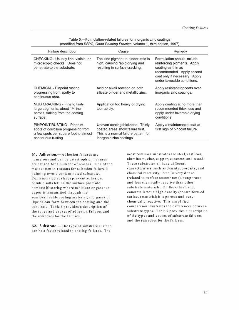
Coating Failures
61
Table 5.—Formulation-related failures for inorganic zinc coatings(modified from SSPC, Good Painting Practice, volume 1, third edition, 1997)
Failure description Cause Remedy
CHECKING - Usually fine, visible, ormicroscopic checks. Does notpenetrate to the substrate.
The zinc pigment to binder ratio ishigh, causing rapid drying andresulting in surface cracking.
Formulation should includereinforcing pigments. Applycoating as thin asrecommended. Apply secondcoat only if necessary. Applyunder favorable conditions.
CHEMICAL - Pinpoint rustingprogressing from spotty tocontinuous area.
Acid or alkali reaction on bothsilicate binder and metallic zinc.
Apply resistant topcoats overinorganic zinc coatings.
MUD CRACKING - Fine to fairlylarge segments, about 1/4-inchacross, flaking from the coatingsurface.
Application too heavy or dryingtoo rapidly.
Apply coating at no more thanrecommended thickness andapply under favorable dryingconditions.
PINPOINT RUSTING - Pinpointspots of corrosion progressing froma few spots per square foot to almostcontinuous rusting.
Uneven coating thickness. Thinlycoated areas show failure first. This is a normal failure pattern forinorganic zinc coatings.
Apply a maintenance coat atfirst sign of pinpoint failure.
61. Adhesion.—Ad hes ion fa ilu res a re
nu m erou s and can be catastroph ic. Failures
are cau sed for a nu m ber o f reasons. On e of the
m os t co m m on rea so n s fo r ad h es ion failu re is
p ain tin g ov er a con ta m in ate d su bst ra te .
Con ta m in ate d su rfaces p rev en t a d h esio n .
Solub le salts left on th e su rface pro m ote
osm otic blis ter ing w here m oisture or gaseou s
v a p or is tr an sm i tte d th r ou g h th e
sem ip erm eable coating m ater ia l , and gases or
liqu ids can form betw een the coating an d the
sub strate. Table 6 p rovid es a descr ip t ion of
the types and cau ses of ad hes ion fa ilu res and
th e rem ed ies for th e failu res.
62. Substrate.—Th e typ e o f su bstr at e su rfa ce
can be a factor related to coating fai lu res. The
m ost com m on su bstrates are s teel, cast iron,
a lu m in u m , zin c, co p p er , con crete , an d w ood .
These sub strates all have d ifferen t
ch aracter ist ics , su ch as d en sit y , p orosit y , an d
chem ical reactivity. Steel is ver y d en se
(related to su rface sm ooth n ess), n on p oro u s,
an d less chem ically reactive th an other
subs t ra te m ater ia ls . On the o ther hand ,
concrete is not a h igh d ensity (non u niform ed
sur face) m ater ia l; it is porous and very
chem ically reactive. This sim p lif ied
com p arison i llustrates the d ifferen ces betw een
sub strate typ es. Table 7 p rovid es a descr ip t ion
of the typ es and causes of su bstrate fai lu res
an d th e rem ed ies for th e failu res.

Guide to Protective Coatings: Inspection and Maintenance
62
Table 6.—Adhesion-related failures(modified from SSPC, Good Painting Practice, volume 1, third edition, 1997)
Failure description Cause Remedy
BLISTERING - Small to large(1/32 to 1 inch plus)hemispherical bubbles in thecoating that contain gases orliquids. Bubbles may rangefrom 1 per square foot toseveral hundred per squarefoot.
Blisters may be due to poorsurface preparation, internalsoluble materials (salts), or poorwetting of substrate. Osmosiscauses absorption of gases intosubstrate or solvent entrapment(also referred to as “solventblistering”).
Select a coating with very strongadhesion strength and low moisturevapor transfer rate. Ensure cleansubstrate with proper surfacepreparation and reduced soluble saltlevels to suit service exposure.
FLAKING or SCALING - Smallto large (1/16 to 1 inch plus)pieces of coating, curling atedges. Easily removed fromsurface, leaving substrateexposed.
Normally, coating is brittle, withinternal shrinkage characteristicsand marginal adhesion strength. Oil type coatings may scale orflake from galvanized surface(never apply an alkyd to agalvanized surface).
Select a coating with very strongadhesion strength and low moisturevapor transfer rate. Ensure cleansubstrate with proper surfacepreparation and reduced soluble saltlevels to suit service exposure. Forgalvanized surfaces, use a primercompatible with zinc.
INTERCOAT DELAMINATION -Coatings that do not adhere tothe previous coat. Failure isbetween the primer and theintermediate coat or betweenthe intermediate coat and thetop coat. The substrate is notnormally exposed.
Coating material is notcompatible with undercoat;undercoat surface may becontaminated with dust, dirt,overspray, or othercontaminates; or undercoat mayhave cured beyond maximumrecoat time.
Select a coating with goodcompatibility and adhesion betweencoats. Ensure that the undercoatsurface is clean before applying thenext coat. For epoxies, do not exposeto moisture (water and humidity) orexcessive sunlight before applying thenext coat.
PEELING - Coating may besmooth and lying on the surfaceor hanging in shreds. Little orno adhesion is evident.
Adhesion is less than the tensilestrength of the coating. Coatingpeelings can easily be pulledfrom the surface down to baresubstrate.
Select a coating with very strongadhesion strength and low moisturevapor transfer rate. Ensure that thesubstrate is clean, the surface hasbeen cleaned properly, and salt hasbeen reduced to levels suited to theservice exposure.
UNDERCUTTING - Corrosionbyproducts from the substratebuild up under the coating andwill break the coating at edgesor pinholes. The corrosionprogresses under the coating.
Poor adhesion because ofimproper surface preparation(dirt, dust, soluble salts, othercontaminates); smooth surface(no surface profile); or coatingincompatibility with the substratesurface.
Select a coating with very strongadhesion strength. Apply coating overa surface that has been abrasivelycleaned or cleaned by water jetblasting. Use of a zinc-rich primerreduces undercutting.
63. Application.—Co ating failur es are m ost
comm only related to the m ethod of
ap p lication. There are a var ie ty of reasons for
ap p licat ion -re lat ed failu res th at h av e n ot h in g
to d o w ith m aterial selection or im p rop er
form u lation. These fai lu res are m ainly cau sed
by h u m an s. Th ere are n u m erou s e xa m p les,
r an g in g fr om f ailu r e to u n d e rsta n d th e
con sequ en ces of im p rop er ly p rep ar in g
su rfaces to im p rop erly ap p lying coating s to
ru shing the job. Table 8 p rovid es a descr ip t ion
of ap p lication failu res, the cau se of the failur es,
an d the rem ed y for the failures

Coating Failures
63
Table 7.—Substrate-related failures(modified from SSPC, Good Painting Practice, volume 1, third edition, 1997)
Failure description Cause Remedy
AGED STEEL - The surfaceincludes blisters, rust, pitting,tubercles, or adhesion loss inareas where the substrate wasexposed to a corrosiveenvironment.
Substrate surface retainedminute corrosion byproducts orcontaminants even if it wasabrasively blasted or water jetblasted to a high degree ofcleanliness.
Water jet blast surface with water;dilute phosphoric acid; or salt-bonding, chemical-removalsolution. Apply an anticorrosionprimer or barrier coating with highadhesion strength.
AGED CAST IRON - The surfaceincludes blisters, rust, pitting,tubercles, or adhesion loss inareas where the substrate wasexposed to a corrosiveenvironment.A silver gray to a dark gray colormay indicate graphite corrosion. This kind of corrosion can beeasily cut or pierced with a knife.
Cast iron has a rough, moreporous, crystalline surface matrixthan steel, causing moremoisture to be retained.
For graphite corrosion, it is theselective leaching of ferrous ionsfrom some cast irons, normallygray cast iron.
Water jet blast surface with water orsalt-bonding chemical removalsolution. Heat surface to hot-to-touch to drive off moisture. Brushapply primer while surface is warmto allow a maximum wet-coatpenetration. Select compatibleintermediate coat and/or topcoat.
GALVANIZED or METALLICZINC - White zinc corrosion by-product developing under orbreaking through the coating.
Formation of zinc salts (oxide,sulfide, oxychloride, zinc soaps)under the coating.
Brush or low-pressure water-jetblast zinc surface or treat withcommercial zinc treatment solution. Select an inert, nonoil primer withhigh adhesion strength.
ALUMINUM - White aluminumcorrosion by-product is causingpinpoint coating failure, adhesionloss from smooth surface,blistering, or pitting.
Environmental pH outside therange of 5 to 8.5. Lack ofaccessible oxygen. Lack ofadhesion to a very smoothaluminum oxide surface, i.e., lackof sufficient surface profile.
Light dust blast or soft abrasiveblast or treat with commercialaluminum treatment solution. Select a compatible primer withhigh aluminum surface adhesionstrength.
COPPER - Blue or gray-greencorrosion by-products, adhesionfailure blistering, or pitting.
Lack of adhesion to a verysmooth copper surface (nosurface profile) or the presence ofoxides on surface.
Light brush blast, soft abrasiveblast, or treat with commercialcopper treatment solution. Select acompatible primer with high coppersurface adhesion strength.
CONCRETE - Adhesion loss,blistering, or peeling of coating.
Chemically reactive and highmoisture content. Formation ofcalcium salts under the coating. Pinholes, air, and water pocketsin concrete surface. Water vaportransmission through concrete.
Abrasive blast or water jet blast(acid etching not recommended) toobtain clean and dry surface. Select a low molecular weight, highpenetrating primer with high alkaliresistance (coal tar epoxy ormodified epoxy).
64. Design.—N u m er ou s co atin g failu res
occur , not b ecau se of m isform u lated m ater ials,
d efic ient sur face p rep arat ion, or app lication
er ror s b u t b eca u se of t h e in h er en tly d ifficu lt
p rob lem s p resen ted by th e d esign of the
s tr u ct u r e. M o s t d e s ig n e rs d o n o t h a v e
corro sion m echa n ism s an d coating op era tions
in m in d w h en th ey d esig n st ru ctu res.
H o w e v er , w i th th e p ro p er se le ctio n of co atin g
m a t er ia ls a n d a p p lica tio n te ch n iq u e s, m a n y
d esign inad equ acies can be over com e. Table 9
p rov ides a d escrip tion of d esign failu res, the
cau se of the failur es, an d the r em ed y for th e
failu res.
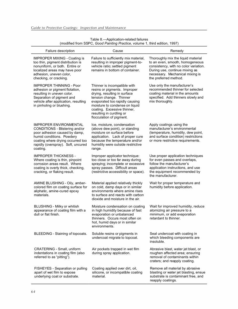
Guide to Protective Coatings: Inspection and Maintenance
64
Table 8.—Application-related failures(modified from SSPC, Good Painting Practice, volume 1, third edition, 1997)
Failure description Cause Remedy
IMPROPER MIXING - Coating istoo thin, pigment distribution isnonuniform, or both. Entire orlocalized areas may have pooradhesion, uneven color,checking, or cracking.
Failure to sufficiently mix material,resulting in improper pigment-to-vehicle ratio; settled pigmentremains in bottom of container.
Thoroughly mix the liquid materialto an even, smooth, homogeneousconsistency, with no color variation. During use, continue mixing asnecessary. Mechanical mixing isthe preferred method.
IMPROPER THINNING - Pooradhesion or pigment flotation,resulting in uneven color. Separation of pigment andvehicle after application, resultingin pinholing or blushing.
Thinner is incompatible withresins or pigments. Improperdrying, resulting in surfacetension change. Thinnerevaporated too rapidly causingmoisture to condense on liquidcoating. Excessive thinner,resulting in curdling orflocculation of pigment.
Use only the manufacturer’srecommended thinner for selectedcoating material in the amountsspecified. Add thinners slowly andmix thoroughly.
IMPROPER ENVIRONMENTALCONDITIONS - Blistering and/orpoor adhesion caused by damp,humid conditions. Powderycoating where drying occurred toorapidly (overspray). Soft, uncuredcoating.
Ice, moisture, condensation(above dew point), or standingmoisture on surface beforeapplication. Lack of proper curebecause the temperature and/orhumidity were outside restrictiverange.
Apply coatings using themanufacturer’s environmental(temperature, humidity, dew point,and surface condition) restrictionsor more restrictive requirements.
IMPROPER THICKNESS -Where coating is thin, pinpointcorrosion areas result. Wherecoating is overly thick, checking,cracking, or flaking result.
Improper applicator technique: too close or too far away duringspraying; incomplete or excessivespray passes. Difficult areas(restrictive accessibility or space).
Use proper application techniquesfor even passes and overlaps,follow the manufacturer’s application instructions, and usethe equipment recommended bythe manufacturer.
AMINE BLUSHING - Oily, amber-colored film on coating surface foraliphatic, amine-cured epoxymaterials.
Material applied relatively thicklyon cold, damp days or in similarenvironments where amine risesto surface and reacts with carbondioxide and moisture in the air.
Wait for proper temperature andhumidity before application.
BLUSHING - Milky or whitishappearance of coating film with adull or flat finish.
Moisture condensation on coatingin high humidity because of fastevaporation or unbalancedthinners. Occurs most often onhot, humid days or in similarenvironments.
Wait for improved humidity, reduceatomizing air pressure to aminimum, or add evaporationretardant to thinner.
BLEEDING - Staining of topcoats. Soluble resins or pigments inundercoat migrate to topcoat.
Seal undercoat with coating inwhich bleeding components are insoluble.
CRATERING - Small, uniformindentations in coating film (alsoreferred to as “pitting”).
Air pockets trapped in wet filmduring spray application.
Abrasive blast, water jet blast, orroughen affected area; ensuringremoval of contaminants withincraters; and reapply coating.
FISHEYES - Separation or pullingapart of wet film to exposeunderlying coat or substrate.
Coating applied over dirt, oil,silicone, or incompatible coatingmaterial.
Remove all material by abrasiveblasting or water jet blasting, ensuesubstrate is contaminant free, andreapply coatings.

Coating Failures
Table 8.—Application-related failures(modified from SSPC, Good Painting Practice, volume 1, third edition, 1997)
Failure description Cause Remedy
65
HOLIDAYS - Bare areas on thesubstrate that were not coated bythe applicator (also referred to as“painter’s holiday”).
Improper and inconsistentapplication technique, reflecting alack of care. Most often occurs inareas difficult to coat.
Apply coating in a careful andprofessional manner, consistentwith industry standards.
LIFTING - Wrinkling, swelling, orblistering appearance on the filmsurface.
Solvents in a coating attack orswell the underlying coating,resulting in film distortion.
Remove all material by abrasiveblasting or water jet blasting andreapply coatings.
ORANGE PEEL - Overallappearance is bumpy. Filmsurface is smooth but irregular. Resembles skin of an orange.
Note: Orange peeling is not acoating failure, but theappearance may beobjectionable.
Inherent with sprayed-onmaterials; caused by improperapplication techniques: gun toofar from surface, solventevaporation too rapid, spraypressure too low for properatomization, paint particles fallingoutside of spray pattern, ormaterial too viscous.
Brush out excess paint beforematerial cures. Correct spraytechnique. After material hascured, sandpaper surface beforeapplying another topcoat thatreacts more slowly.
OVERSPRAY - Very roughcoating surface. Surface may bedry, pebbly, or sandy. Somecoated areas may have theappearance of dryness or feel dry(also referred to as “dry spray”).
Improper application techniques: gun too far from surface, solventevaporation too rapid, spraypressure too low, atomizingpressure too high, paint particlesfalling outside of spray pattern, ormaterial too viscous.
Before the material cures, removethe overspray by dry brushing,followed by solvent wiping. Afterthe material has cured, wire screenand sandpaper the surface beforeapplying another topcoat thatreacts more slowly.
PINHOLES - Small, tiny, deepholes (1/32 inch) in coating,normally through to the substrate. Generally, the distribution ofholes appears to be random.
Improper application techniques: gun too far from surface, solventevaporation too rapid, spraypressure too low, atomizingpressure too high, paint particlesfalling outside of spray pattern, orpigment settlement.
Correct any improper applicationtechniques. If pinholes alreadyexist and the material has notcured, apply additional coat bybrushing into holes. If material hascured, but it is still within the recoatwindow, apply an additional coat. Ifoutside the recoat window, abradesurface and apply additional coat.
RUNS or SAGS - Downwardmovement of coating material on vertical or curved surfaces in theform of droplets or streams. Runs are the result of excessmaterial continuing to flow afterthe surrounding surface has set.Sags are the result of differencesbetween application and settingtimes. Sags have theappearance of a curtain.
Excessive application of coatingmaterial, spray gun too close, toomuch thinner, surface too hard orglossy to hold material, ortemperature too cold for properdrying.
Correct any improper applicationtechniques. Apply thinner coats. Ifmaterial has not cured, brush outexcess material. If material hascured and is still within the recoatwindow, apply an additional coat. Ifoutside the recoat window, abradesurface and apply additional coat.

Guide to Protective Coatings: Inspection and Maintenance
Table 8.—Application-related failures(modified from SSPC, Good Painting Practice, volume 1, third edition, 1997)
Failure description Cause Remedy
66
SPATTER COAT - Areas of thincoating (less than specifiedcoating thickness), normally atend of the spray pass or aroundcomplex sections of structure. Under good lighting conditions,coating appears continuous;under poor lighting, coatingappears discontinuous. Maydevelop into pinpoint corrosion ata later date.
Improper application techniques,causing a noncontinuous coatingover the surface: inconsistentspray passes not overlapping by50 percent, spray gun flipped atend of spray pass, or spray gunnot held perpendicular to thesurface.
Correct any improper applicationtechniques. If material has notcured, apply additional coat. Ifmaterial has cured but it is stillwithin the recoat window, apply anadditional coat. If outside therecoat window, abrasive blast orwater jet blast all material off andrecoat.
Table 9.—Design-related failures(modified from SSPC, Good Painting Practice, volume 1, third edition, 1997)
Failure description Cause Remedy
BACK-TO-BACK ANGLES andPLATES - Corrosion betweenback-to-back angles and plates isresulting in undercutting ofcoating.
Impossible to apply coating increvice between angles andplates.
Design: Use T bar or pipe inconstruction.
Precoat: Coat angles and platesbefore construction assembly.
Stopgap measure: Fill crevice withresinous chalking and topcoat withcompatible material.
EDGES - Linear corrosion alongedge and undercutting coating away from the edge.
Surface tension causing coatingto pull away from edges.
Brush or stripe coat surfacesbefore full coating. Overlap fullcoating on both sides of edges. Spray directly at edge to build upthickness and reduce surfacetension.
INTERIOR CORNERS - A void orblister is developing undercoating.
Excessive coating thickness,resulting in coating shrinkageduring or after curing.
Apply multiple thin coats and allowcoating to thoroughly dry betweencoats, but within recoat window.
SKIP WELDS - Corrosion in weldgaps and between overlappingmetal is causing undercutting ofcoating.
Impossible to apply coating increvices in weld gaps andbetween metal surfaces.
Provide continuous weld in gapsand overlap areas before applyingcoating in any corrosiveenvironment.
SMALL DISCONTINUOUSAREAS - Corrosion is developingon edges of bolt heads, boltthreads, nuts, washers, rivets,and other small edged orcornered surfaces.
Small surfaces with high ratio ofedges and corners to plain, flatarea will increase coating surfacetension and cause coating to pullaway from edges and cornerpoints.
Brush or stripe coat surfaces priorto full coating. Overlap brush orstripe coat with each full coatapplied. Applying multiple thincoats is more beneficial than onethick coat.

Coating Failures
Table 9.—Design-related failures(modified from SSPC, Good Painting Practice, volume 1, third edition, 1997)
Failure description Cause Remedy
67
STORAGE TANK ROOFS(Interior of umbrella type forcenter post and rafters) -Corrosion is developing betweenroof and rafter and betweenlapped roof plates.
Impossible to apply coating increvices between roof and rafterand between lapped roof plates.
Butt weld or double weld roofplates. Precoat rafters andunderside of roof.
WELDS - Corrosion along welds,particularly hand welds, isundercutting coating away fromweld. Corrosion along weld maybe continuous or discontinuous.
Welding flux in undercuts alongweld. Rough weld surfaces. Soap remaining after pressuretesting of welds. Blue scale(similar to mill scale) remaining onweld surface.
Remove all soap solution and bluescale. Grind rough welds smoothor nearly smooth. For interior ofhydraulic structures, such aspipelines, grind welds down to1/8 inch, minimum. Abrasive blastweld and apply brush or stripe coat2 to 3 inches on each side of weld,working coating into all roughareas before applying full coating.
65. Exterior Forces.—Th e en v ir on m e n t th e
coating is su bject to can be a p r imary cause of
failu re. C or ros ive e n v iron m en ts n or m ally
encoun te red on Reclam at ion p ro ject s a re
freshw ater environm ents that contain var ious
concen t ra t ions o f d is so lved sa lt s and flow ing
w ater tha t conta ins abras ive m ater ia l such as
sand p ar t icles . In th is sect ion , ord inary
atm osp h er ic exp osu res a re n ot con sid ered .
Table 10 prov ides a d escription of fai lu res
related to exterior forces, the cau se of the
failures, and the rem ed y for the failures
Table 10.—Failures related to exterior forces(modified from SSPC, Good Painting Practice, volume 1, third edition, 1997)
Failure Description Cause Remedy
ABRASION or EROSION -Thinning or wearing away ofcoating is resulting in a baresubstrate subject to corrosion.
Wear caused by wheeled traffic,impact, wind, or liquid-borneabrasives.
Select coating with strongadhesive properties and specificabrasion and erosion resistance. Thoroughly prepare surface (near-white blast minimum) and applynew coating.
CAVITATION - Loss of coatingand metal material. Appears astiny craters overlain by multiplecraters in metal surface,accompanied by significant metalloss.
Drop in water vapor pressure,forming air bubbles thatrepeatedly collapse at highpressure.
Select coating with strongadhesive properties and highcavitation resistance.
CHEMICAL - Dissolution ofcoating; undercutting or underfilmcorrosion.
Selection of unsuitable coatingmaterial. Improper coatingapplication.
The prime requirement is to selecta coating for the specific chemicalservice exposure.

Guide to Protective Coatings: Inspection and Maintenance
Table 10.—Failures related to exterior forces(modified from SSPC, Good Painting Practice, volume 1, third edition, 1997)
Failure Description Cause Remedy
68
FAYING SURFACES - Coatingfailure and corrosion in joint area.
Concentration (or crevice)corrosion caused by oxygendifferences between closelyspaced or joined coated surfaces,subject to friction-producingmovement (e.g., steel plates andhigh strength bolts).
Precoat metal surfaces beforeassembly with inorganic zinccoating or a suitable coating with ahigh coefficient of friction.
GRAFFITI - Painted words orgraphics over coated surface.
Vandals painting coated surfaces,especially with spray cans.
Select the manufacturer's graffitiremover and antigraffiti coating

69
Bibliography
Bechtel Pow er Corp oration, Steel Stru ctures
Pain tin g Cou n cil, Coat ing and
Lin in g Inspect ion M anual, P ittsb u r gh ,
Pen n sy lvan ia, 1991.
Bookcock, Simo n K., R.E.F. W eaver,
B. Ap p lem an , an d G.C. Soltz , Effects on
Surface Contaminant s on Coating Life.
Bechtel Pow er Corp oration, Steel
Stru ctu res P aintin g C ou n cil, Pittsbu rg h ,
Pen n sy lvan ia, 1991.
D ep ar tm en t o f th e N av y , Paint Failures -
Causes and Rem edies , N a v y C iv il
Engineering Laboratory , Port H u enem e,
Califor n ia, 1982.
Ele ctr ica l Pow er Rese arch In st itu te , In c.,
Steel P en stock Coa tin g an d Lin in g
Reh abilit a tio n : A H ydropower Technology
Roun dup R eport, volu m e 3, TR-113584,
Plea sa n t H ill, Ca lifor n ia, 2000.
Fitz im on s, Bren d an , Protect ive Coatin g
In spect ion M anual, Rob in so n Irw in
Tech n ical Su p p or t Lt d ., En glan d , 1997.
Fitz im on s, Bren d an , V isual Com parison
M anu al: A pplication and Coatin g D efects.
Ro bin so n Irw in Tech n ica l Su p p or t L td .,
En glan d , 1998.
Generic Coatin g T ypes: A n In troduct ion to
Indu strial M aint enance Coating M aterials,
Sm ith, Lloyd M ., ed ., Techn ology
P u b lish in g C om p a n y, P ittsb u r gh ,
Pen n sy lvan ia, 1996.
M u n ger , Ch ar les G ., Corrosion Prev ention
by Protective Coatin g, N at ional Associat ion
of Cor rosion Eng ineer s, H ou ston , Texas,
1984.
N A CE In te rn ation al, N A CE Corrosion
Engineer' s R eference Book, second ed it ion,
R.S. Trese d er , R. Baboian , an d
C.G. M u n ger , ed s., H ou ston , Texas, 1991.
N ation al A ssocia tion of Corrosio n En gin eers,
Corrosion Basics: A n In troduct ion , H o u s to n ,
Texa s, 1984.
The Society of Pro tective Co ating s, Good
Pain tin g Pract ices, volu m e 1, th ird ed it ion ,
John D. Keane, Dean Berger , H arold
H o w er , Bern an d R. A p p lem a n, Josep h
Bro n o, Kitt i Con d iff, M ark O 'D on n ell,
Janet Rex, Aim ee Beggs , Vilm a Macura ,
Te rry Sow ers, a n d M on ica M ad au s, e d s.,
P itt sb u rgh , Pe n n sy lvan ia, 1993.
The Society of Protective Coatings, Steel
Str u ctu res P ain tin g Cou n cil, Systems and
Specificat ion s, volum e 2, seventh ed it ion,
Ber n ard R. A p p lem an , Jan et Rex, a n d
Ter ry Sow ers, eds . P it tsburgh ,
Pen n sy lvan ia, 1995.
Th e Socie ty of Prote ct iv e Coatin gs, T he
Inspection of Coatings an d Lin ings: A
H andbook of Basic Practice for Inspectors,
O w ners, and Specifiers, Bernard R.
A p p lem an , Rich ard W . Drisko, Ju d ith K.
N eu gebau r, Simo n K. Bookcock, Russel
Davison , Law rence J. Grab iak , CIH , CSP,
Jan et Rex, a n d Te rry Sow ers, e d s.,
P itt sb u rgh , Pe n n sy lvan ia, 1997.
Th e Socie ty of Prote ct iv e Coatin gs, C-1:
Fun dament als of Protective Coatings
for In dust rial S tru ctures , versio n 10,
P itt sb u rgh , Pe n n sy lvan ia, 1999.
Th e Socie ty of Prote ct iv e Coatin gs, C-3:
Supervision /Com pet ent Person Train in g for
D eleadin g of Indust rial S tru ctures , tw o
volum es, ve rsion V7-T, P it tsburgh ,
Pen n sy lvan ia, 1999.
Th e Socie ty of Prote ct iv e Coatin gs, C-2:
Specifying and M anaging Protect ive Coatin g
Projects, tw o volu m es, v ersio n 7,
P itt sb u rgh , Pe n n sy lvan ia, 2000.
Guide to Protective Coatings
70
Th e Socie ty of Prote ct iv e Coatin gs,
SSPC-V IS 2: S tandard M ethod of Evaluatin g
D egree of Rust in g on Pain ted S teel S urfaces,
P itt sb u rgh , Pe n n sy lvan ia, 2000.
Th e Socie ty of Prote ct iv e Coatin gs, Surface
Preparation S pecifications, P ittsb u r gh ,
Pen n sy lvan ia, 2000.
The Society of Pro tective Co ating s,
SSPC-V IS 4/N A CE V IS 7: Guide and
Reference Photographs for S teel S urfaces
Prepared by W aterjet t ing, P ittsb u r gh ,
Pen n sy lvan ia, 2001.
Th e Socie ty of Prote ct iv e Coatin gs,
SSPC-V IS 5/N A CE V IS 9: Guide and
Reference Photographs for S teel Surfaces
Prepared by W et A brasive Blast Cleaning,
P itt sb u rgh , Pe n n sy lvan ia, 2001.
Th e Socie ty of Prote ct iv e Coatin gs,
SSPC-S P 15: Com m ercial Grade Pow er T ool
Cleaning, P itt sb u rgh , Pe n n sy lvan ia, 2002.

A-1
Appendix A
Organizational Sources for Standards and References
A m erican Society of Testing an d M ater ials (A STM)
1916 Race Street
Ph ilad elp h ia P A 19103
Telep h on e: (610) 832-9500
Fax: (610) 832-9555
Webs ite Ad d ress : w w w .as tm .org
N A CE In ter n ation al (N A CE)
PO Box 218340
H ou ston TX 77218
Telep h on e: (218) 228-6223
Fax: (281) 228-6329
Webs ite Ad d ress : w w w .nace.org
Socie ty for Prote ct iv e Coatin gs (SSP C)
40 24th Str eet, 6 th Floor
Pitt sb u rgh PA 15222
Telep h on e: (412) 281-2331 ext 16
Fax: (412) 281-992
Webs ite Ad d ress : w w w .sspc .org
Bu reau of Reclam ation
G u id e Sp e cifica tio n s
W eb site A d d re ss: h ttp :/ / in tr a.u sb r.g ov / gu id esp ecs

B-1
Appendix B
Reading Sources
Goo d Painting Pra ctice, Steel Stru ctur es Painting M an u al, Volum e 1, Third Ed ition , 1993. (The four th
ed it ion is d u e in 2003.)
Sys tem s a n d Sp ecifica tio n s, Steel Str u ctu res Pain tin g M an u al, Volu m e 2, Eig h th Ed itio n , 2000.
Coating an d Lining Insp ection M an u al, Bechtel Corp oration, 1983, exclusively d istr ibuted by Steel
Str u ctu res Pain tin g Cou n cil (SSPC ), Au gu st 1991, SSPC Pu blicat ion N o. 91-12.
Th e In sp ect ion of Coatin gs a n d Lin in gs, A H an d book of Bas ic P ract ice for In sp ectors, O w n ers, a n d
Sp ecifie rs, SSPC Pu blicat ion N o. 91-12, Fir st Ed itio n , 1997.
Corr osion P reven tion b y Protective Co atings, by C ha rles G. Mu ng er, Pu blished by N AC E
In te rn atio n al, Firs t Ed itio n , 1984.
Pain tin g : N ew Con st ru ctio n an d M ain ten an ce, U .S. Ar m y Cor p s o f En gin ee rs, M an u al N o. EM 1110-2-
3400, Ap r il 30, 1995.
FH W A Field M an u al for Bridg e Paint Inspection, U.S. Dep artm ent of Transp ortat ion, Feder al
H igh w ay A d m in ist ra tio n (FH W A ), FH W A Brid ge C oa tin gs Te ch n olo gy Team , Octo ber 1997.
Steel Penstock Co ating a nd Linin g Reh abilitation, A H yd rop ow er Techn ology Rou nd u p Rep ort,
Vo lu m e 3, Te ch n ical Rep or t TR-113584-V3, A u gu st 2000.
Av ai lable from Electr ic Power Research Inst itute (EPRI), 3412 H illview Av enu e, Palo Alto CA
94304; t elep h on e: (650) 855-2000; C u stom er Serv ice: (800) 313-3774; W ebsit e A d d ress:
w w w .ep ri .com
Visu al Com p ar iso n M an u al, Ap p licat ion an d Coa tin gs D efe cts , Bren d an Fitz im on s, Ro bin so n Irw in
Tech n ical Su p p or t Lt d ., En glan d 1997-1998, (SSPC Pu blicat ion N o. 00-8)
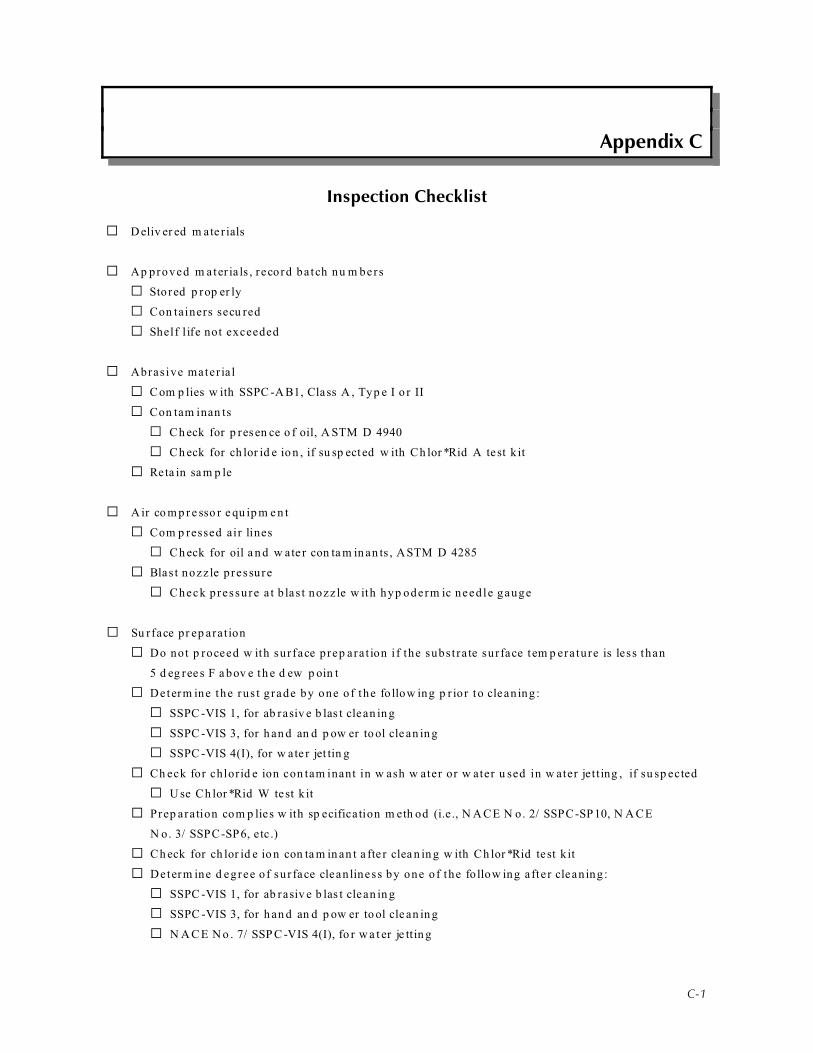
C-1
Appendix C
Inspection Checklist
G D eliv er ed m ate r ials
G Ap proved m ater ia ls , r ecord ba tch nu m bers
G Sto red p rop er ly
G Con tainers secu red
G Shelf l ife not exceeded
G Abras ive mater ia l
G Com p lies w ith SSPC -A B1, Class A , Typ e I o r II
G Con tam inan ts
G Ch eck for p resen ce o f oil, A STM D 4940
G Ch eck for ch lor id e io n , if su sp ect ed w ith Ch lor *Rid A te st k it
G Reta in sa m p le
G A ir co m p r e sso r e qu ip m e n t
G Com p ressed air lines
G Ch eck for oil a n d w ate r con ta m in an ts , ASTM D 4285
G Blas t nozz le p ressure
G Check pressure a t b las t nozz le w ith hyp oderm ic need le gauge
G Su rface pr ep arat ion
G Do not p roceed w ith surface prep ara t ion i f the subs t ra te surface tem p era ture is less than
5 d eg ree s F a bov e th e d ew p oin t
G Determ ine the rus t g rade by one of the fo llow ing p r io r to clean ing :
G SSPC -VIS 1, for ab rasiv e b las t clean in g
G SSPC -VIS 3, for h an d an d p ow er to ol cle an in g
G SSPC -VIS 4(I), for w ate r jet tin g
G Ch eck for chlorid e ion con tam inant in w ash w ater or w ater u sed in w ater jet t ing , if su sp ected
G U se Ch lor *Rid W te st k it
G Prep aration com p lies w ith sp ecification m eth od (i.e ., N A CE N o. 2/ SSPC-SP10, N A CE
N o. 3/ SSPC-SP6, etc .)
G Ch eck for ch lor id e io n con ta m in an t a fte r clea n in g w ith Ch lor *Rid te st k it
G Determ ine d egree o f sur face clean liness by one of the fo llow ing a fte r clean ing :
G SSPC -VIS 1, for ab rasiv e b las t clean in g
G SSPC -VIS 3, for h an d an d p ow er to ol cle an in g
G N A C E N o . 7/ SSP C -VIS 4(I), fo r w a t er je ttin g
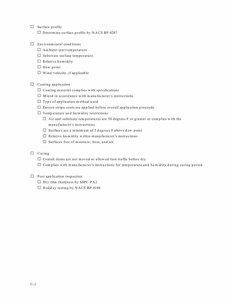
C-2
G Su rface p rofile
G D eter m in e su rface p rofile by N A CE RP 0287
G Environm ental cond it ions
G Am bien t (a ir ) t em pera ture
G Subs t ra te sur face tem pera ture
G Relative h u m idity
G D ew p o in t
G W in d velo city , if ap p licab le
G Coating ap p lication
G Coating m ater ia l comp lies w ith sp ecifications
G M ixed in accord ance w ith m anu factu rer’s instru ctions
G Typ e of ap p lication m ethod u sed
G Ensu re str ip e coats are ap p lied before overall ap p lication p roceeds
G Temp erature an d hu m id ity res t r ic tions
G A ir and su bstrate tem p eratu res are 50 d egrees F or g reater or com p lies w ith the
m a n u f actu r er ’s in str u ctio n s
G Su rface s a re a m in im u m of 5 d eg ree s F a bov e d ew p oin t
G Relat ive hu m id ity w ithin m anu factu rer’s instru ctions
G Su rfa ces fre e o f m ois tu re , frost, a n d ice
G C u r in g
G Coated it ems a re no t m oved or a llow ed foot tra ffic before d ry
G Com p lies w ith m anu factu rer’s instru ctions for tem p erature an d hu m id ity d u ring curing p er iod
G Post app lication insp ect ion
G Dry film th ickness by SSPC-PA2
G H olid ay te st in g by N A CE RP 0188

D-1
Appendix D
Reference Standards Cited in Guide
American Society for Testing and Materials (ASTM)
ASTM A 123 Zinc (Hot-Dip Galvanized) Coatings on Iron and Steel Productions
ASTM A 153 Zinc (Hot-Dip) Coatings on Iron and Steel Hardware
ASTM A 591 Steel Sheet, Electrolytic Zinc-Cated, Light Coating Weight [Mass] Applications
ASTM A 653 Steel Sheet Zinc-Coated (Galvanized or Zinc-Iron Alloy-Coated (Galvanized) by the Hot-
Dip Method
ASTM B 633 Electrodeposited Coatings of Zinc on Iron and Steel
ASTM B 695 Coatings of Zinc Mechanically Deposited on Iron and Steel
ASTM D 3359 Measuring Adhesion by Tape Test
ASTM D 4138 Field Measurement of Dry Film Thickness of Protective Coating Systems by Destructive
Means
ASTM D 4285 Indicating Oil and Water in Compressed Air
ASTM D 4414 Measurement of Wet Film Thickness by Notch Gages
ASTM D 4417 Field Measurement of Surface Profile of Blast Cleaned Steel
ASTM D 4541 Pull-Off Strength of Coatings Using Portable Adhesion Testers
ASTM D 4940 Conductimetric Analysis of Water Soluble Ionic Contamination of Blasting Abrasives
ASTM D 5064 Conducting a Patch Test to Assess Coating Compatibility
ASTM D 5162 Discontinuity (Holidays) Testing of Nonconductive Protective Coating on Metallic
Substrates
ASTM E 337 Measuring Humidity with a Psychrometer (the Measurement of Wet- and Dry-Bulb
Temperatures)
ASTM E 832 Laboratory Filter Papers
American Welding Society (AWS)
AWS C2.2 Recommended Practices for Metallizing with Aluminum and Zinc for Protection of Iron
and Steel

D-2
NACE International (NACE)/Society of Protective Coatings (SSPC)
NACE RP 0188 Discontinuity (Holiday) Testing of New Protective Coatings on Conductive Substrates
NACE RP 0287 Field Measurement of Surface Profile of Abrasive Blast Cleaned Steel Surfaces Using
a Replica Tape
SSPC-AB1 Mineral and Slag Abrasives
SSPC-PA2 Measurement of Dry Paint Thickness with Magnetic Gages
SSPC-SP1 Solvent Cleaning
SSPC-SP2 Hand Tool Cleaning
SSPC-SP3 Power Tool Cleaning
SSPC-SP8 Pickling
SSPC-SP15 Commercial Grade Power Tool Cleaning
SSPC-SP11 Power Tool Cleaning to Bare Metal
NACE No. 1/
SSPC-SP5
White Metal Blast Cleaning
NACE No. 2/
SSPC-SP10
Near-White Metal Blast Cleaning
NACE No. 3/
SSPC- SP6
Commercial Blast Cleaning
NACE No. 4/
SSPC-SP7
Brush-Off Blast Cleaning
NACE No.5/
SSPC-SP-12
Surface Preparation and Cleaning by High- and Ultrahigh-Pressure Water Jetting Prior
to Coating
NACE No. 8/
SSPC-SP-14
Industrial Blast Cleaning
SSPC-VIS 1 Abrasive Blast Cleaned Steel (Standard Reference Photographs)
SSPC-VIS 2 Evaluating Degree of Rusting on Painted Steel Surfaces
SSPC-VIS 3 Power- and Hand-Tool Cleaned Steel (Standard Reference Photographs)
NACE No. 7/
SSPC-VIS 4
Guide and Visual Reference Photographs for Steel Cleaned by Water Jetting
NACE-VIS 9/
SSPC-VIS 5
Guide and Reference Photographs for Steel Surfaces Prepared by Wet Abrasive Blast
Cleaning

E-1
Appendix E
Inspection Equipment
Inspectio n G auges , Ins trum ents, an d Ki ts:
• A d h es ion te ster (Elcom eter ), d es tr u ctiv e t es tin g (op tio n al)
• Blast n oz zle a n alyzer gau ge (o p tio n al)
• Calibrated sh im s
• Con d u ctivity m eter
• Dry film th ickness gauge
• Pu ll-off
• Fixed or cons tan t p ressure p robe
• En v iron m en ta l m et er for am bien t a n d su rface tem p er atu re, h u m id ity , an d d ew p oin t
• H olid ay d et ect or (op tio n al):
• Low voltage
• H igh vo l tage
• M icrom eter and repl ica tape
• N oz zle o r ifice g au ge (o p tio n al)
• P it g au ge (o p tio n al)
• Pres su re n ee d le g au ge (o p tio n al)
• Sling p sychrom eter
• Sw ab che cks for lead an d chrom ate
• Test k its , ch lor id e io n sp ecific (C h lor *Rid In te rn atio n al)
• Th er m om eter w ith m agn et ic back in g
• Took e g au ge, d es tr u ctiv e d ry film th ickn ess in st ru m en t (o p tio n al)
• Wet film th ickness gauge
Inspection Tools:
• Flash ligh t
• 1 to 1-1/ 2 inch w id e st iff pu t ty kn i fe w ith sharpened edge
• Kn ife
• Latex gloves
• Plast ic booties
• M agn et

F-1
Appendix F
Example of Inspection Daily Check Sheet
COATING DAILY INSPECTION REPORT 1 of 2
Project: Date:
Feature: Report By:
Contract No: Paint Contractor:
SPECIFICATIONS Tabulation No: ______ Item to be Coated: _____________________________
Coating Category: ________ Total DFT (min.): ______ mils Tab Surface Prep. Method: _________
Coat No. Material Manufacturer Product Name DFT Range
Primer:
Intermediate:
Topcoat:
WEATHER Reading Time:
1. Substrate Temperature (degrees F):
2. Ambient (Dry Bulb) Temp. (degrees
F):
3. Wet Bulb Temperature (degrees F):
4. Relative Humidity (percentage):
5. Dew Point Temperature (degrees F):
6. Item (1) minus (2) (in degrees F):
7. Wind (mph) and Direction:
Comments:
SURFACE PREPARATION Surface Preparation Method
Used:
SSPC-SP _____ / NACE No. ______
Abrasives: Manufacturer: ______________ Product Name: _____________ Class A, Type _____
Contaminants (ASTM D 4940): Fines __ yes / __ no; Oil __ yes / __ no; pH ____; Conductivity_______
Chloride Specific Ion: Test Method Used __________________________; Results _____________
Compressor Air: Type: _____________ ______ CFM Passes ASTM D 4285: ___ yes / ___ no
Surface Profile (NACE RP 0287): No. Measurements Taken ______; Averaged Measured ______
mils
Cleanliness: Chloride Specific Ion: Test Method Used _____________ _; Results _____________
Visual Standards (SSPC/NACE): VIS 1 __ yes / __ no; VIS 2 __ yes / __ no; VIS 4 (I) __ yes / __ no

F-2
COATING DAILY INSPECTION REPORT 2 of 2
APPLICATION AND MATERIALS
Manufacturer Product Name Batch Number Gal Color Thinner
Product Gal/Oz %
Environmental Control: Heaters ___ yes / ___ no; Dehumidification ___ yes / ___ no, Unit Size _________
Material Mixing: Power Mixing Time _____ minutes; Induction Time ___ yes / ___ no, _____ minutes
Stripe Coats Applied: ___ yes / ___ no; Method: ___ Bush/Roller ___ Spray
Application Method: ___ Brush; ___ Roller; ___ Airless; ___ Conventional; ___ Plural; ___ Electrostatic
Applied Within Recoat Window: Primer __ yes /__ no; Intermediate __ yes /__ no; Topcoat __ yes /__ no
Wet Film Thickness (WFT): Primer ______ mils; Intermediate ______ mils; Topcoat ______ mils
Comments:
TESTING OF HARDENED COATING
Dry Film Thickness (DFT) by SSPC-SP PA2:
Area Inspected: ___ less than 300 ft2; ___ less than 1,000 ft2; ___ equal to or greater than 1,000 ft2
Number of 5 Spot Measurement Groups Taken Within Above Inspected Area: _____ at _____ 100 ft2 areas
Average of 5 Spot Measurement Groups _______ mils; Conform to Specifications ___yes /___no
Discontinuity (Holiday) Testing by NACE RP 0188
Tester Used: _____ Low Voltage (Sponge) _____ High Voltage
Set at _______ volts; Number of Defects Found _______; Defects Repaired ___ yes / ___ no
Comments:

G-1
Appendix G
Procedure for Detecting Moisture and Oil in Compressed Air
(ASTM D 4285)
A. Purpose
Th is tes t d et ect s th e p resen ce o f m ois tu re a n d oil co n ta m in an ts in com p ressed air for ab rasiv e
blast ing , air blast cleaning, and coating ap p lication o p erations. The contam inants are d etected
v isua lly .
B. Equipm ent
W h ite ab so rben t m ate r ial, filte r p ap er , blo tt er p ap er , or clot h w ith a r ig id back in g .
C . Pro ce d u re
1. A llow th e air com p ressor to rea ch op era ting cond ition s.
2. Shu t off the abrasive flow .
3. Place the absorbent m ater ia l w ith in 24 inches of the d ischarge-point -centered a i r st ream an d
d ow n strea m from th e in-lin e oil and m oistu re sep ara tors.
4. Allow air to flow for 1 m inu te.
5. Visu ally ch eck ab so rben t m ate r ial fo r th e p resen ce o f m ois tu re o r oil.
A ny observ ed contam inan ts on th e cloth or in th e air flow w ill requ ire corre ctive action. Tests
sh ou ld be p erform ed at t h e beg in n in g of th e sh ift or after th e air com p ressor h as b een sh u t o ff.
Test in g is r eco m m en d ev er y 4 h ou rs d u r in g b las tin g op er atio n s o r m or e fr eq u en tly if hu m id ity is
h ig h .

H-1
Appendix H
Procedure for Detecting Chlorides and Soluble Salts in
Abrasives by Conductivity Method
A . Purpose
To detect and d eterm ine the level of solu ble salts in abr asives to prev ent sub strate d eter iorat ion
an d sub sequ ent coating fai lu re.
B. Conductiv i ty Method
1. Eq u ip m e n t
a . Electron ic cond u ctivity m eter
2. Procedu re
a . Ca libr ate th e cond u ctivity m eter a ccord ing to th e m an u factur er’s instru ction s.
b . Place equal volu m es of abras ive m ater ia l and d is t illed or d e-ionized w ater in a g lass and
st ir for 1 m in u te . Let stan d for 8 m in u te s a n d st ir ag ain for 1 m in u te . A llow th e a brasiv e
m aterial to set t le .
c. In se r t th e co n d u ctiv ity m eter p rob e in th e w ate r w ith ou t co n ta ctin g ab rasiv e m ate r ial.
d . A llow th e con d u ctiv ity m eter to stab ilize in accord an ce w ith th e m an u factu rer ’s
instru ction s.
e. Read an d record th e d irect read in g in m icr osie m en s.
C. Chloride-Spec if ic Ion M ethod
1. Pu rp ose
To d eterm ine th e concentr ation of chlorides in a bra sive m aterials and p rev en t su bstrate
contam ination a nd sub sequ ent coating fai lu re.
2. Eq u ip m e n t
CH LO R*TEST A , Ch lor id e Io n Test For A brasiv es tit ra tio n k it

H-2
3. Procedu re
a . Ov erfill the smal l conta iner w ith abras ive b las t m ater ia l and level-off w ith the m eta l
snap p er inclu d ed w ith th e kit or w ith a straigh t ed ge.
b . Rem ov e th e lid fro m th e C H LO R*EXTRA CT so lu tio n con ta in er an d p ou r th e lev ele d -off
blast abrasive m ater ia l into the solut ion.
c. Replace the lid of the CH LOR*EXTRAC T solu t ion container and vigorously shake for 2
m inu tes. Al low the abras ive m ater ia l to se t tle for about 5 minu tes before proceed ing. Clear
solu tion sh ou ld be v isible abou t a ½ inch from the top sur face.
d . H old the t it ra t ion tu be along th e m id d le . Do n ot han d le or touch the n arrow end s before or
after snap p ing th em off. H an d ling of the ti tration tu be n arr ow end s can conta m inate th e
solution w ith bod ily p ersp iration , i .e. , salts, an d affect the resu lts. Sna p off both end s of the
ti tr a tion tu be an d h old th e tu be in th e so lu tion w ith th e b lu e ar row h ead p oin tin g u p . Do
not insert the t i t rat ion tu be into the ab rasive m aterial because th is m ay p lug th e tub e.
e. A llow th e t itr a tio n tu be to r em ain in th e e xt racte d so lu tio n u n til th e solu tio n h as w icked -u p
to th e t op of t h e co tton w icket . Satu ratio n of t h e w icket is com p let e w h en th e co tton tip
changes to an am ber co lor .
f. Im m ed iately after th e cotton tip ha s chan ged to an am ber color, rem ove the ti tration tu be
from the tes t s leeve and read the chlor ide level a t the interface of the p ink-w hite color
ch an ge. W h ite in d icat es th e p resen ce o f ch lor id e. If n o co lor ch an ge o ccu rs (r em ain s a ll
p ink ), th e chlor id e leve l is be low th e th resh old d etection lim it of the titration kit. The
chlorid e concentrat ion level is read d irectly from the t i t rat ion tu be in m icrogra m s per
square cen t im eter o r pp m .

I-1
Appendix I
Procedures for Detecting Chloride Ion in Water
A . Purpose
To determ ine the concentrat ion of chlor id e ions in w ater used w ith w ater je t t ing b last cleaning or
for w ater evalu ation to p reven t sub strate contam ination a nd sub sequ ent coating fai lu re.
B. Eq u i p m e n t
CH LO R*TEST W , Ch lor id e Io n Test For W ate r / Liq u id s t itr a tio n k it
C. Pro ce d u re
1. Rem ove d rop p er assem bly cap from bott le.
2. U se the d rop p er assem bly in th e bottle to tr an sfer th e w at er to be t es ted . Ad d ab ou t a ½ in ch
of wa ter to the bott le.
3. H old the t it ra t ion tu be along th e m id d le . Do n ot han d le or touch the n arrow end s before or
after snap p ing th em off. H an d ling of the ti tration tu be n arr ow end s can conta m inate th e
solution w ith bod ily p ersp iration (i.e.), salts, an d affect the resu lts. Sna p off both end s of the
t it ra tion tube and ho ld the tube in the so lu t ion w ith the b lue a r row head po in t ing u p .
4. A llow the ti tration tu be to rem ain in th e extracted solution u ntil the solution ha s w icked -up to
the top of cot ton w icket . Sa tura t ion of the w icket is com p le te w hen the cot ton t ip chan ges to an
am ber co lor .
5. Im m ed iately af ter the cotton t ip has chang ed to an am ber color , rem ove the t i tra t ion tu be from
th e te st sle ev e an d read th e ch lor id e lev el a t t h e in te r face of th e p in k-w h ite co lor ch an ge.
W hite ind icates the p resen ce of chloride. If no color cha ng e occu rs (rem ains all p ink), the
ch lor id e lev el is belo w th e th resh old d et ect ion lim it o f th e t itr a tio n k it. Th e ch lor id e
concentrat ion level is read d irectly from the t i t rat ion tu be in m icrogra m s per squ are centimeter
or p p m .

J-1
Appendix J
Procedures for Determining Blast Cleaning Air Pressure
A . Purpose
To m easure the b las t hose air p ressure for assessing abras ive b las t clean ing e fficiency .
B. Eq u i p m e n t
H yp od erm ic need le p ressur e gau ge, 0 to 120 p ou nd s per squ are inch (psi) or m ore.
C. Pro ce d u re
1. Blast clean ing e qu ipm en t is to be op era tiona l at the tim e of testing. If m ore th an on e blast h ose
is to be u sed , ope rate all blast h oses.
2. In se r t h yp od er m ic n ee d le p res su re g au ge in to th e in te r ior of t h e b las t h os e im m ed iat ely in
front of the b last nozzle an d slan t the n eed le at a 45 deg ree an gle so that i t is p ointed in the
d irection th e abrasives are f low ing to m inim ize need le clogging and d am age.
3. Read th e b las t clean in g air p res su re d irect ly fro m th e d ial g au ge. N or m al b las t p res su re is
betw ee n 90 an d 100 p si.
4. Pr essu re r ead ings sh ou ld be ta ken p eriod ically or w h en blast clean ing e fficiency d ecreases.
N O TE:
1. U se th is tes t m eth od on ly for ab rasiv e b las t h os es . Do n ot u se th is m eth od on coa tin g
ap p lication h oses.
2. There is no cu rrent s tand ard reference to de termine b las t p ressu re ; ASTM D 4264 w as
w ith d r a w n .

K-1
Appendix K
Determination of Environmental Factors
Environm ental factors are d eterm ined by var iou s instru m ents , and som e instru m ents can p erform
m u ltiple fu nctions. Electron ic and d igital instrum ents are becom ing increasing ly m ore accu rate,
fas te r , m or e a ffor d ab le, an d accep ta b le. Th e in st ru m en ts ar e n ot d et a iled belo w beca u se of w id e
va riation am on g instru m en t typ es an d becau se of the va riation in the w ay instru m en ts are u sed . Bu t,
as w ith an y instrum ent , a lw ays follow the m anu factu rer’s instru ctions. The follow ing sect ions
d escr ibe the ins t rum ent and the p rocedu res to be used to de term ine each env i ronm enta l facto r :
A . Am bient Temp erature by Thermom eter
1. Descr ip t ion of the Procedu re
a . Determ in ing the am bien t tem pera ture by a s ing le d irect read ing w ith a the rm om eter .
2. Eq u ip m e n t
a . A therm om eter o r the d ry bu lb therm om eter o f a psychrom eter .
3. Procedu re
a . A m bien t t em p er atu re sh ou ld be t aken n ea r th e su rface to be co ated . Loca te all
th er m om eter s a n d in st ru m en ts w h er e t h ey ar e n ot su b ject to d irect su n ligh t, w in d ,
constru ction l ighting, heating or ven tilat ion d u cts, and w her e they ar e not su bject to other
cond ition s th at w ou ld affect tru e tem p era tu re r ead ings.
b . Let tem pera ture equ ipm ent stab ilize fo r 1 to 2 m inu tes if it was b rough t from a p lace w here
th e t em p er atu re w as d iffer en t fr om th e a rea w h er e t h e e qu ip m en t w ill be u sed (e.g ., an air
con d itio n ed or h ea ted roo m or n ex t to s om eo n e's bod y).
c. A ll instru m en ts are d irect read . For electron ic instru m en ts, follow instru ction s an d en su re
that the correct m od e is being u sed an d the read ing is on the d esired scale, d egrees F or
Celsiu s.
B. S u b s trate S u rf ace Te m p e ratu re
1. Descr ip t ion
a . Determ ining the su rface tem p eratu re of the sub strate to be coated
2. Eq u ip m e n t
a . Dial th erm om eter w ith a m ag n etic base

K-2
3. Procedu re
a . Place the d ial therm om eter on the s teel substrate and allow the tem p erature to s tabilize for
ab ou t 2 to 3 m inu tes.
C. Re lati ve H um id ity and D ew Po in t (A STM E 337)
1. Descr ip t ion
a . D eter m inin g r elative h u m id ity an d d ew p oin t to a scerta in if eva p or ation w ill occu r. The
su bstrate su rface is to be at least 5 d egrees F abo ve th e d ew p oint.
2. Eq u ip m e n t
a . Psy chr om eter, either slin g or batt ery , and p sych rom etric table an d char ts.
b . Electr on ic or d ig ita l m et er (p rov id es d irect rea d in gs).
3. Proced u re for Psychrom eter
a . Th e w ick o f a w et bu lb p sy ch ro m eter (cott on sock) sh ou ld be r ela tiv ely clean . Dir ty w icks
need to be cleaned or rep laced .
b . Sa tura te the wick on the w et bu lb , bu t keep the d ry bu lb thermom eter d ry .
c. W hirl (sling typ e) or op erate fan (battery typ e) un til the th erm om eters stabilize, abou t 20 to
30 second s, and note th e tem p eratu re.
d . Repea t s teps 2 and 3 w ithout re -w et ting the w ick un t il two or m ore wet bu lb read ings a re
equ al to the low est temp eratu re obtained .
e. Record th e d ry (air) an d w et bu lb tem p era tu res.
f. The relat ive hu m id ity is determ ined from the intersect of the d ry an d w et bulb read ings on
p sychro m etric tables or char ts. Psychr om etric tables and charts n orm ally ar e inclu d ed w ith
the in stru m en t.
4. D ew P oin t
a . U sing th e p sych rom etric tables:
(1) Determ ine the atm osph eric (barom etr ic) p ressure for your geogr ap hical location from
U .S. Dep ar tm en t o f Com m er ce o r U .S. Wea th er Bu rea u ta b les . Th e a v er age b arom et r ic
p res su re a t sea lev el is ab ou t 30 in ch es of m er cu ry , an d it w ill av er age le ss th an 30
inche s at h ighe r eleva tions.

K-3
(2) D et er m in e th e d iffer en ce b etw ee n th e d ry an d w et bu lb tem p er atu res . Th e w et bu lb
tem p eratu re is alw ays less than the d ry b u lb. The d ifference is com m on ly called the
“d ep ress ion of th e w et b u lb .”
(3) From th e t ab les , loca te you r geo grap h ic at m os p h er ic p res su re (lo cated in ta b le h ea d er ),
d ry bu lb temp era ture (row head er), and d epress ion of wet bu lb (colu m n h eader) and
d eterm ine the corresp ond ing d ew p oint value. Dew p oint is given in d egrees
Fah ren h eit or Ce lsiu s.
D . W i n d
1. Descr ip t ion
a . Deter m ining w he n th e w ind velocity can cau se in d ry sp ray , over sp ray , or d am age to
nearby equ ipm ent , m etalw ork , o r p rop er ty .
2. Eq u ip m e n t
a . Ro ta tin g van e a n em om eter s, d irect d ial, o r electr on ic (d ig ita l)
3. Procedu re
a . P lace or h old th e in st ru m en t in th e d irect ion of th e w in d an d read th e w in d (a ir ) v elocity .
Digita l anem om eters m ay requ ire holding d ow n a sw itch or bu t ton for a fixed p er iod of
tim e to d eterm ine th e av era ge a ir velocity. Follow th e m an u factur er’s instru ction s.

L-1
Appendix L
Procedures for Detecting Chloride Salts on Prepared or Existing Surfaces
A . Purpose
To detect chlor ide ions and their concentrat ion level on p rep ared surfaces or exis t ing su rfaces for
p recoating evalu ation to p reven t sub strate contam ination a nd sub sequ ent coating fai lu re.
B. Eq u i p m e n t
CH LO R*TEST t itr a tio n k it
C. Pro ce d u re
1. Test a sp ot w here the surface is re la t ive ly sm ooth . Do not p ick ir regular surfaces su ch as
corrosion p its and w eld sp atter , and d o no t p ick areas betw een d ep ressed and raised su rfaces
becau se these su rfaces m ay allow the solu tion to leak ou t.
2. Pou r the en tire contents from the solution bott le into th e test sleeve.
3. Peal off the b lu e backing f rom th e adh es ive s t r ip on the op en end of the tes t s leeve and
d iscard the backing. Rem ove a ir from the tes t s leeve by squeezing betw een fingers and
thu m b. Do n ot sp ill any o f the solution. If solution is lost, d iscard the test sleeve an d the
rem aining solution a nd bega n w ith a n ew kit .
4. A p p ly th e a d h es ive s tr ip of t h e t es t s lee v e to t h e t es t su r face an d firm ly p res s th e a d h es ive
strip to en su re a p rop er seal. For ap p lying the a d he sive strip to h orizon tal surfaces, allow the
solution to fil l the closed end of the test sleeve a nd squ eeze th e test sleeve in th e m idd le w ith
ind ex an d m id d le finge rs to p rev en t solu tion loss.
5. M assage th e solu tio n ag ain st th e t es t su r face for 2 m in u te s. A ll th e solu tio n sh ou ld be
exp os ed to th e t es t su r face d u r in g m assag in g to ex tr act a n y ch lor id e sa lts . Th e fo llow in g
p roced u res ar e r eco m m en d ed for th e v ar iou s tes t su r face p os itio n s, so th at th e solu tio n w ill
flow tow ard s th e test su rface w ithou t solu tion loss.
a . H orizon tal and ver tical - Lift the closed end of the test sleeve u p , allow ing th e solution to
flow tow ard s the test surface.
b . Ov erhead - Lift the closed end of the tes t s leeve up , a llow ing the so lu t ion to flow tow ard s
the m idd le of the test sleeve. The n sq u eeze th e em p ty p ortion o f the test sleeve w ith the
ind ex and m id d le fingers an d s lid e the fingers a long the tes t sleeve, forcing th e solu t ion
to the test surface.

L-2
If th e solu tio n is leak in g ou t fr om th e t es t s lee v e, d isca rd th e t es t s lee v e a n d th e r em ain in g
solution an d begin w ith a n ew kit .
6. A fter m assag ing th e solu tion for 2 m inu tes, rem ov e th e test sleeve a n d solu tion from th e test
su rface . To r em ov e th e t es t s lee v e a n d ret a in th e solu tio n fro m th e t es t su r face , th e fo llow in g
p roced u res ar e recom m en d ed for th e va riou s test su rface p osition s:
a . Vertical and over he ad - Low er th e test sleeve, allow ing th e solution to flow tow ard the
closed end of the test s leeve.
b . H orizontal - W ith th e test sleeve laying flat , squ eeze the solution tow ard s the closed end
of t h e t es t s lee v e. Th en , p in ch off a n d lift u p th e t es t s lee v e n ea r th e t es t su r face , allo w in g
the solution to f low tow ard s the closed end of the test s leeve.
7. Pu n ch ou t th e p er for ated h ole on th e lid of t h e o r ig in al box con ta in er lid , close t h e b ox lid ,
an d insert the test sleeve w ith th e solu tion into th e hole.
8. H old the t it ra t ion tu be along th e m id d le . Do n ot han d le or touch the n arrow end s before or
after snap p ing th em off. H an d ling the ti tration tu be n arr ow end s can conta m inate th e
solution w ith bod ily p ersp iration (i.e.), salts, an d affect the resu lts. Sna p off both end s of the
t it ra tion tube and ho ld the tube in the so lu t ion w ith the b lue a r row head po in t ing u p .
9. A llow th e t itr a tio n tu be to r em ain in th e e xt racte d so lu tio n u n til th e solu tio n h as w icked -u p
to the top of cotton w icket . Satu ration of the w icket is com p lete w hen the cotton t ip chan ges
to an am ber co lor .
10. Im m ed iately after th e cotton tip ha s chan ged to an am ber color, rem ove the ti tration tu be
from th e te st sle ev e an d read th e ch lor id e lev el a t t h e in te r face of th e p in k-w h ite co lor ch an ge.
W hite ind icates the p resen ce of chloride. If no color cha ng e occu rs (rem ains all p ink), the
ch lor id e lev el is belo w th e th resh old d et ect ion lim it o f th e t itr a tio n k it. Th e ch lor id e
concen t ra t ion leve l is read d irect ly from the tit r a tion tube in m icrograms p er square
cen t im eter o r pp m .
11. After com p let ing th e test , c lean the tes t su rface (sub strate) w ith acetone or a lcohol to remov e
all ad hesive str ip resid u e.
N OTE: The pr esence of som e salt ions an d cer ta in p H rang es can ad versely affect the above
chlorid e test resu lts in th e follow ing w ay s:
• The p resence of brom ide, iod ide, or cyan ide ions can yield a high er concentrat ion level
than the actua l chloride ions extracted from the test surface.
• The p resen ce of sulp h id e ions can tu rn th e cotton w ick in th e titration tu be a br ow n ish
color ra th er th an w h ite an d can y ield a h igh er con cen tr a tio n lev el th an th e a ctu al ch lor id e
ions extracted from the test surface.
• p H values of less than 3 .5 and h igher than 11 can y ie ld a h igher concent ra tion level than
the actua l chloride ions extracted from the test surface.

M-1
Appendix M
Determining Surface Profile of Blast-Cleaned Steel Using Replica Tape
(NACE RP0287 or ASTM D 4417, Method C)
A . D escription
To d eterm ine the an chor p attern d ep th of abrasive blasted sur faces by u se of a sp ring m icrom eter
an d rep lica im p ression tap e.
B. Eq u i p m e n t
1. Sp ring m icrom eter
2. Rep lica im p ression tap e, coar se or e xtra coar se
C. Pro ce d u re
1. M easu rem en ts are to be ta ken on a sm ooth , flat or cu rv ed p late that is free of su rface dirt ,
d u st , and abrasive p ar t ic les that w ill d is tor t resul ts . An accu rate prof ile cann ot be m ad e on
p itted or p artially coated are as.
2. Select the corr ect rep lica tap e ran ge for th e sp ecified p rofile dep th
a . 0 to 2 m ils, u se coarse
b . 1.5 to 4.5 m ils, u se extra coarse
The rep l ica t ape has a th ickness o f 2 m ils bu t w ill va ry s ligh t ly .
3. Prep are th e sp r in g m icr om ete r by clean in g th e an v ils , se tt in g th e gau ge to zero, an d
ca lib ratin g w ith a sh im betw een 1 an d 4 m ils . Th e sp r in g m icr om ete r sh ou ld be p recise to 0.3
m il.
4. Rem ov e a sin g le p iece of r ep lica im p res sio n ta p e fr om con ta in er an d p u ll off th e a d h es ive
ba cking . The r elease p ap er (n on ad h esive p iece) w ith th e circle can be d iscard ed . The
m ea su r in g p ap er st r ip h as a 0.4 inch sq u are w h ite p las tic film at th e ce n te r of t h e a d h es ive
back .
5. Before ap p lying the f ilm to th e blasted sur face, the th ickn ess of the f ilm m u st be sub tracted
from the final read ing. Su btra ction of the film thickness can be accom p lished by o ne of the
follow ing m eth od s:

M-2
a . M easure the rep lica tap e w ith the sp r ing m icrometer a t the rou nd cutou t port ion
opp os ite the 0.4 inch square wh ite p last ic film and sub t ract the rep l ica film th ickness by
on e th e follow ing m eth od s:
(1) Subt ract the th ickness from the fina l read ing .
(2) Turn the d ia l ind ica tor a rm on the spr ing m icrom eter coun te r clockw ise from zero
the m easu red rep lica fi lm thickn ess (e.g. , for a m easu red 2.2 mils fi lm thickn ess, set
th e d ial in d icat or ar m at 7.8). Th is m eth od com p en sa te s fo r th e r ep lica film
th ickness and prov ides a d i rect read ing .
b . N om in al th ickn ess o f th e r ep lica t ap e is 2 m ils. In stea d of m ea su r in g th e r ep lica t ap e, it is
accep ta b le p ractice to u se th e 2 m il n om in al th ickn ess a n d su b tr act th e r ep lica film
th ickness by one the fo llow ing:
(1) Subt ract the th ickness from the fina l read ing .
(2) Set the d ial ind icator a rm at 8.0 (tu rn ing it cou nter clockw ise from zero) on the
spr ing m icrom eter to p rov ide a d irect read ing .
6. Ap p ly the fi lm to the blasted su rface. The ad hesive backing w ill hold th e fi lm in p lace.
7. W ith a rou nd ed tool (a bar p lastic sw izzle stick has b een foun d to w ork w ell), ru b ov er th e
rou nd cutou t p ortion o f the rep lica tap e w ith m od erate p ressu re. The circu lar area of the
rep lica ta p e w ill b ecom e d arker or gray ish , in d ica tin g th e b last ed p rofile h as b een rep lica te d .
Ensu re the en tire circular area h as u niform ly da rken ed .
8. Rem ove the r ep lica tap e an d p lace it betw een the a nv ils of the sp ring m icrom eter (w ith
circu lar a rea centered betw een the anvi ls ). Gent ly re lease the t r igger of the m icrom eter and
take read ing. Depend ing on the gauge se t ting , either zero or the m easured repl ica tape
th ickness, ensure o r ig ina l rep l ica t ape th ickness is sub t racted from read ing .
9. Three read ings shou ld taken in on e locat ion w ith in abou t 3 inches of each o ther and
averaged . Loca t ion read ings (th ree averaged read ings) should be t aken on every 100 square
feet of sur face, or p ort ion thereof, to establish consistency of the p rofile.
10. Retain r ep licated tap e sam p les for futu re reference.

N-1
Appendix N
Procedures for Measuring Wet Film Thickness (ASTM D 4414)
A . Purpose
To d eterm ine th e w et coating th ickn ess bein g ap p lied an d to estim ate th e d ry film th ickn ess.
B. Eq u i p m e n t
A n otch gau ge is a rectangu lar or squ are-shap ed p late . Each ed ge has tw o ou ter project ions of
eq u al h eig h t. Betw ee n th e o u te r p ro ject ion s is a se rie s o f gr ad u at ed n ot ch es m ar ked in m ils. Each
ed ge of the notch gau ge is ca libra ted for a sp ecific m il th ickness range . Typica l notch gau ge
m ate r ials ar e a lu m in u m , p las tic, p olish ed stee l, an d sta in less s te el.
N O TE: Th e p lastic gau ge s ar e d isp osa ble an d ar e int en d ed for a lim ited n u m be r o f read ing s. The
alum inu m and p last ic gaug es w ill wear d ow n an d becom e ina ccu rate w ith extend ed u se.
C. Pro ce d u re
1. If p ossible, test a flat area . For cur ved su rfaces, test along th e longitu d inal axis, no t the
curved axis . Test smooth areas that are free from surface ir regu lar i ties su ch as seam s or
w eld s.
2. Select the m il th ickn ess ran ge a long th e ed ge o f the g au ge for th e an ticipa ted film th ickn ess.
3. Test imm ed iately after the coating is ap p lied .
4. Firm ly p ress the g au ge into th e w et coating , ho ldin g th e gau ge p erp en d icu lar to the su bstrate
w ith the tw o equa l ou te r p ro ject ions res ting on the subs t rate . Do no t tilt o r scrape the gauge
through the wet coa t ing .
5. Rem ove the g au ge from the w et coating an d no te the sh ortest coated step betw een the
notches. The w et fi lm thickn ess lies betw een th is valve an d the ad jacent u ncoated step.
6. Clean the g au ge before tak ing th e next m easu rem en t.

O-1
Appendix O
Wet Film Thickness Formulas and Example Calculations
A . D escription
D eter m inin g th e w et film th ickne ss (W FT) to a chiev e a d esired d ry film th ickne ss (DFT)
B. Formu las
W it hou t Thinn in g t he Coatin g M aterial
N ote: Percen t o f so lid s by vo lum e is expressed in d ecim al fo rm .
Exam p le: The d esired DFT is 8 m ils. The coa ting m ater ial conta ins 83 per cent solid s by
vo lu m e. Dete rm ine t h e W FT to ach ieve a n 8-m il DFT.
W it h T hinn in g t he Coatin g M aterial
N ote: The percen t o f so lid s and th inners ad d ed by vo lum e is expressed in d ecim al fo rm .
Exam p le: Th e sp ecifie d D FT is 6 m ils . Th e su rface areas r equ ires 5 g allon s o f th in n ed p ain t.
Th e co atin g m ate r ial co n ta in s 86 p er cen t solid s, by volu m e. Th e m an u fact u rer 's
ins t ruc t ions s ta te 1½ pints of th inn er is add ed to each gal lon of coat ing m ater ia l
(16 p ints = 1 gallon ). De ter m ine t h e W FT to ach ieve a 6-m il DFT.

P-1
Appendix P
Procedures for Dry Film Thickness Gauges (SSPC-PA2) and Example
I. Purpose
Determ in ing the th ickness o f a hard ened coa ting .
II. Eq u i p m e n t
The n on d estru ctive gau ges d escribed in SSPS-PA 2 are gr ou p ed into tw o ge n era l categ ories:
Typ e I, m agn etic pu ll off gau ge.
Typ e II, fixed p rob e or con stan t p ressu re p rob e ga u ges.
III. Type I, Magnetic Pul lo f f Gauge
A. Descr ipt ion
Typ e I, m agn etic p u ll off gau ges, com m on ly referred to as “ba na na ” gau ges, m easu re th e
coat ing th ickness of a non-m agnet ic coat ing over a fer rous m eta l subs t ra te. The gauge has an
exp osed m agn et attached to a sp ring . The am ou nt o f tension ap p lied on the sp ring to lift the
m agn et from the coated su rface is d irectly pr op ortiona l to the d istan ce of the m agn et from the
ferrou s surface.
B. Cal ibrat ion
1. U se n on m ag n etic, stan d ard calibr ated shim s, com m on ly chro m e. Plastic and m ylar sh im s are
not acceptable for ca libra t ing p u ll off gau ges becau se p las t ic or m ylar is nonad herent and
m ay cause the magne t w ith in the gauge to lift p rem ature ly .
2. Select a shim that w ill be in th e ran ge of the expected d ry f ilm th ickn ess to be m easu red .
3. Place the shim on the p rep ared su bstrate o r an y clean bar e steel an d p lace the g au ge on the
sh im .
4. Ro ta te th e d ial fo rw ard u n til th e m agn et con ta cts th e sh im .
5. Ro ta te th e d ia l back w ard slo w ly an d ev en ly u n ti l th e m agn et b reaks con ta ct an d lift s u p . A
click ing sound m ay be heard .
6. If th e rea d ing d oes n ot ag ree w ith th e sh im th ickn ess, ch eck th e m ag n et for clean lin ess.
7. If the read ing is st ill not in agreem ent w ith the shim thickness , the gau ge is out of cal ibrat ion
an d sh ou ld be re-calib rated by th e m an u factu rer or rep laced . Follow th e m an u factu rer ’s
in st ru ct ion s fo r ad ju st m en t o r retu rn th e gau ge to th e m an u factu rer for factory ad ju st m en t.
D o n ot ad ju st th e g au ge y ou rse lf.

P-2
8. The gau ge is to calibr ated before u se, du ring u se, and after u se to v erify accur acy of rea d ings.
C . P rocedu re
1. Ensure the m agnet is clean .
2. H old th e ca librated gau ge fir m ly to th e co ated stee l su r face an d rot a te th e d ial fo rw ard u n til
the m agn et contacts the coated su rface.
3. Ro ta te th e d ia l back w ard slo w ly an d ev en ly u n ti l th e m agn et b reaks con ta ct an d lift s u p . A
clicking sou n d m ay be h ear d . The follow ing m ay influ en ce read ings:
a . Vibrations m ay p rem atu rely brea k th e m agn etic contact.
b . Soft or tacky coatings m ay inh ibit the lift ing of the m agn et.
4. Read the coat ing th ickness on the d ia l tha t a ligns w ith the m arked line on the gau ge and
record the read ing .
IV . Ty pe II, Fixe d Prob e or Co nstant Pressure Prob e G auges
A . Descrip t ion
The ty p e II, fixed or con stan t p ressu re p rob e gau ge, m easu res th e m agn etic flu x associated w ith
n on -m ag n etic coating s ap p lied to ferro u s su bstr ates. For reliable read ings, th e ga u ges m u st
rem ain in d irect contact w ith the coated surface un t il a reading i s obta ined . These gauges are
n orm ally faster an d m ore accur ate th an th e m ag n etic p u ll off gau ges.
B. Cal ibrat ion
1. U se n on m ag n etic or p lastic calibr ated shim stan d ard s.
2. Select a shim that w ill be in th e expected ran ge of the d ry f ilm th ickn ess to be m easu red .
3. Place the shim on the p rep ared su bstrate o r an y clean bar e steel an d p lace the g au ge on the
sh im .
4. P lace the gauge firm ly aga ins t the sh im and ob tain a read ing .
5. If the r ead ing d oes n ot agr ee w ith the sh im thickness, ad ju st the g au ge in accord an ce w ith the
m an u factur er’s instru ction s. A d ju stm en t is nor m ally cond u cted by p ressing key s to ad ju st
u p w ard or d ow nw ard u ntil the gau ge rea d ing an d the sh im thickness ar e in agr eem en t.
C . Procedu re
1. Ensure the probe i s clean .
2. Set gau ge to rea d in d esired scale, either m ils or m icrom eters.
3. H old th e calibrated gau ge firm ly to the coated steel sur face.

P-3
4. Read th e coat ing th ickness on th e d igi ta l d isplay. Som e gau ges w ill s tore several readings for
d ow n load ing in to p rinte r an d m ay be cap ab le of avera ging rea d ings.
Examp le:
Sp ecifica tio n s r eq u ire t h e u p st rea m face of a rad ial g ate be co ated . Th e g ate h as th e d im en sio n s o f 26
feet in h eigh t alon g th e ra d ius cu rv atu re a n d is 10 feet in w id th . The coating tabu lation sp ecifies 2
coats of epoxy at 8 m ils per coat and 1 topcoat of p olyu rethan e at 3 m ils for 19-m il DFT, m inim u m , for
the total system .
Step 1: Det erm ine th e n u m ber of sp ot m easu rem en ts req u ired on an are a ba sis.
Su rface area of stru cture: 26 feet x 10 feet = 260 squ are feet
Su rfa ce a re a is less th an 300 squ ar e feet ; ther efo re , 5 sp ot m ea su re m en ts a re re qu ire d in ea ch
of tw o 100 squ are feet ar ea s (tot a l of 30 in d iv id u al gau ge r ea d in gs).
Step 2: The D FT in st ru m en t is calib rated w ith a 20-m il sh im .
Step 3: An im agin ary line is d raw n h or izo n ta lly acr os s th e g ate at th e m id elev atio n , effect ively
d ivid ing the g ate into equ al low er an d u p p er areas. Five spot m easu rem ents are ran d om ly taken
in each area, consist ing of thr ee ind ivid u al gau ge read ings w ithin a 1.5-inch-diam eter circle p er
sp ot m easu rem en t. Th e follow ing a re th e resu lts:
Lower Gate Area
Gaugereading
Spot measurement (DFT in mils)
A B C D E
1 18.2 20.6 21.0 16.7 26.4
2 18.6 19.1 21.8 17.1 29.8
3 17.8 20.4 20.8 16.8 29.0
Average 18.2 20.0 21.2 16.9 28.4
Upper Gate Area
Gaugereading
Spot measurement (DFT in mils)
A B C D E
1 22.6 20.4 18.6 19.5 29.3
2 22.1 21.7 18.3 19.9 31.0
3 21.9 21.3 19.4 19.2 30.4
Average 22.2 21.1 18.8 19.5 30.2

P-4
Ste p 4: Dete rm in e m in im u m an d m axim u m accep ta n ce th ick n ess cr iter ia .
a . The sp ecified coating thickn ess is 19 mils. The al low able cri teria are:
M in im u m - 90 p er cen t o f sp ecified th ickn ess (0.9 x 19 m ils) = 17.1 m ils
M axim u m - 150 p er cen t o f sp ecified th ickn ess (1.5 x 19 m ils) = 28.5 m ils
b. The follow ing evalu ates the resu lts for thickness accep tance:
(1) Av erage spot m easurem ents that are betw een the m inim u m specified thickness of
17.1 m ils an d th e m axim u m sp ecified th ickn ess o f 28.5 m ils
(aa) Sp ot m easu rem en ts A , B, C, a n d E o n th e low er gate area (18.2, 20.0, 21.2, a n d
28.4, resp ectively) are accep table.
(bb) Sp ot m easu rem en ts A , B, C, a n d D on th e u p p er gate area (22.2, 21.1, 18.8, a n d
19.5, resp ectively) are accep table.
(2) Aver age sp ot m easu rem en ts that a re less than the 90 per cent m inim u m of the
sp ecified th ickn ess o f 17.1 m ils a t sp ot m ea su rem en t D on th e lo w er gate ar ea (16.9) ar e
not acceptable.
(3) Av erage sp ot m easu rem ents tha t are greater th an the 150 percent m axim u m specified
thickness of 28.5 m ils a t sp ot m easurem ent E on the u p p er gate area (30.2) are not
accep table.
Step 5: From the abo ve eva luation, the follow ing can be conclud ed :
On e averag e sing le sp ot m easu rem ent (D) on the low er gate area w as less than th e 90 p ercent
m inim u m , and one av erage single spot m easu rem ent (E) on th e u p p er gate area w as greater
tha n th e 150 per cent m axim u m . Therefore, the coating th ickn ess d oes n ot conform to the
m inim u m and m axim u m thickn ess requ irem ents an d is not acceptable.
H ow ev er , ad d it ion al gau ge read in gs a re allow ed to be ta ken to ver ify p rev iou s r esu lts.
Several factors cou ld hav e affected th e gau ge read ings. Possible factors inclu d e cal ibrat ion,
d irty su rface, soft or tacky coating su rface, p roxim ity to ed ges o r oth er steel m asses,
cur va tu re of steel, t i lt ing of p rob e, p ossible oth er n earb y m agn etic sou rces, tem p eratu re
ext rem es, a n d v ib ration s.

Q-1
Appendix Q
Procedures for Discontinuity (Holiday) Testing (NACE RP 0188)
I. Purpose
To locate p inh oles an d oth er d efects in h ard en ed coating u sing low or h igh v oltage in stru m en ts.
II. Using a Low Voltage Instrum ent for Coating Thicknesses of 20 Mils and Less
A . Descrip t ion
A low vol tage, norm ally betw een 5 and 90 vol ts DC, bat tery p ow ered d evice w ith a w et spong e
electric p rob e is d rag ged across the coated su rface to locate d iscon tinu ities (p inh oles) in the
coating fi lm . Shou ld d iscontinu ities be encou ntered , an electr ic curren t w ill flow to the steel
su bst ra te . Th is p rocess w ill close a n electr ical cir cu it w ith in th e in st ru m en t a n d se t o ff an au d ib le
or v isua l a la rm .
B. Eq u ip m e n t
1. The follow ing ar e tw o general types of low vol tage holid ay tes ters . Each u ses a w et spong e
p rob e, bu t th ey a re b ased on d ifferen t electrical pr inciples.
a . Electrom agn etic-sensitive or a solid state electronic relay circu it tha t, w he n d iscon tinu ity
is d et ect ed , closes th e cir cu it a n d p rod u ces an au d ib le o r v isu al ala rm . Ge n er ally , th is
instrum ent can b e field ad ju sted .
b . A n electr on ic re laxat ion oscillato r cir cu it m ea su re s th e d ro p in electr ical r es ista n ce
betw een th e coating and the steel sub strate and p rod u ces an a u d ible alarm w hen
d iscontinu ity is detected. Genera lly, this instru m ent typ e canno t be f ield ad ju sted .
C . Procedu re
1. En su re th e coatin g is su fficie n tly d ry (se e ch ap te r VIII , su bse ct ion 36, “D ry in g , Recoatin g , an d
Cu r ing”) before test ing .
2. Tes t th e in str u m en t's p ow er su p p ly b at te rie s for su fficien t p ow er w ith th e b at te ry ch eck
sw itch . If th e ba tteries ar e low , rep lace or rech arg e th e ba tteries.
3. Test th e in stru m en t for op eration al u se an d calib rate it in accord an ce w ith th e m an u factu rer ’s
instructions or N AC E RP0188, sections 3.3 and 3.4, before its ini t ial use.
4. Attach th e electr ical grou nd (neg ative) w ire from the instru m ent to the steel su bstrate.
5. W et the sp ong e p robe w ith p otable w ater

Q-2
N ote:
a . A low -sud s ing w et ting agen t such as tha t used in ph otograph ic d eve lopm ent can be
ad d ed to th e p otab le w ater at a r atio of ½ fluid ou n ce to 1 gallon of w ater to increa se
sens it iv ity .
b . The u se of d etergen t w ett ing solu tions is not p erm itted because a bu bble m ay form over
a d efect, rend ering i t un d etectable.
6. Turn the instrum ent sw itch to the “on ” p osit ion.
7. Th e sp on ge is to be m ov ed ov er th e co atin g su rface at ab ou t 1 foot p er secon d , u sin g a d ou ble
p ass over each ar ea an d ap p lying su fficient p ressu re to kee p the su rface w et.
8. The spon ge shou ld be kep t sa tu ra ted , bu t no t d r ipp ing w et , w hi le moving over the coa t ing .
9. W h en a d iscon tin u ity is d etected , th e sp on ge is t o b e tu rn ed on ed ge to d eter m in e th e exact
spot of the d efect , and the spot is to be m arked for repai r . Use a grease less m arker tha t can be
ea sily clea n ed off.
10. If w etting solu tions are u sed , the solu tions m u st be com p letely rinsed off before ap p lying the
repa ir coa t ing .
III. Usin g Hig h V oltage Instrum ent for Coating Thickness of G reater Than 20 M ils
A . Descrip t ion
A h igh -volt age d ev ice, n or m ally in exces s o f 800 volt s D C, w ith w et sp on ge e lect r ic p rob e is
p assed ov er th e co ated su rface to loca te d isco n tin u itie s (p in h ole s) in th e co atin g film . Sho u ld
d iscon tinu ities be en cou nter ed , the electric dev ice w ill sp ark thr ou gh the a ir gap at the
d isco n tin u ity an d p rod u ce a n au d ib le o r v isu al ala rm . A gen er al ru le-o f-th u m b for d et er m in in g
the r equ ired voltage is 100 to 125 volts p er m il; ho w ever , i t is best to consu lt the m an u factu rer to
preven t d am aging the coa t ing .
B. Eq u ip m e n t
1. The follow ing a re tw o ge n era l typ es of high vo ltage h olid ay testers:
a . Pu lse typ e—d isch arg es a cyclin g, high -voltage p u lse
b . Di rect cur ren t—d ischarges con t inu ous vo ltage
2. The follow ing a re g en era l typ es of electrod es an d p rob es:
a . H alf- or ful l-circle sp ring electrod es used for p ipes
b . Ph osp hor bron ze bru sh p robes
c. Con d u ctive ru bber str ip p robes

Q-3
C. Procedu re
1. En su re t h e co atin g is su fficien tly d ry befo re t es tin g . (See ch ap te r VIII, su bsectio n 36, “D ry in g ,
Recoatin g , an d Cu r in g .”)
2. If m oisture is p resen t on the coated su rface, d ry th e su rface before testing b ecau se m oisture
w ill in d icate inv alid d iscon tinu ities.
3. Test th e in stru m en t for op eration al u se an d calib rate it in accord an ce w ith th e m an u factu rer ’s
instructions or N AC E RP 0188, sections 4.5 and 4.6, before its ini t ial use.
4. A d ju st th e instru m en t to th e p rop er v oltage sett ing for th e coating th ickn ess.
5. Attach th e electr ical grou nd (neg ative) w ire from instrum ent to the steel su bstrate.
6. Turn the instrum ent sw itch to the on p osit ion.
7. To u ch th e p robe to a bare con d u ct iv e (st eel) su bst ra te to ver ify th at it is p rop er ly grou n d ed .
Electr ic spa rks shou ld be seen , or an alarm sign al shou ld be activated .
8. Using a sing le p ass, m ove th e p robe ov er the coated sur face at a rate of abou t 1 foot p er
se co n d .
9. W he n a d iscon tinu ity is d etected, m ark the sp ot for rep air. Use a grea seless m ark er th at be
ea sily clea n ed off.

R-1
Appendix R
Procedure for Mechanical (Pulloff) Adhesion Testing
(ASTM D 4541; Annex A2)
A . Purpose
To d eterm ine the ad hesive strength betw een a fu lly cur ed coating and the su bstrate.
B. D escription
Th e a d h es ion te ster m ech an ically m ea su res th e r ela tiv e s tr en g th of a d h es ion betw ee n a co atin g
an d th e su bst ra te or betw ee n coa tin g lay er s. A n alu m in u m p u ll off s tu b (d olly ) is ad h es ively
bon d ed to th e co atin g an d allo w ed to cu re. A p u llin g for ce o n th e b on d ed d olly is con tin u ou sly
in crease d u n ti l th e d olly d eta ch es o r a sp ecific force is a ch iev ed .
C. Eq u i p m e n t
Th ere ar e sev era l d ifferen t typ es of p u lloff ad h esion tester s. The ty p e II tester , cited in A STM D
4541, ann ex A.2, is the Elcom eter M od el 106. This mod el is the m ost com m only u sed . Elcom eter
M od el 106 is available in six scale ran ges. The scale m ost com m only u sed is 0 to 1,000 pou nd s per
sq u are in ch (p si), an d it is d iscu ssed belo w . A stan d ard 3/ 4-in ch -d iam eter alu m in u m d olly is
u sed w ith th e Elcom eter M od el 106.
D . Pro ce d u re
1. Select the sp ot w here the d olly w ill be bond ed to the coating . The se lected area m u st be la rge
enou gh to accom m od ate the feet of the instru m ent. Dollies shou ld be located at least 2 inches
from an y su rface obstru ction s an d ha ve at least 1 foot of vertical clearan ce to accom m od ate
inser ting the ins t rum ent in the d o lly .
2. U se a s u ita b le solv en t w ip e to r em ov e su rface con ta m in an ts su ch as d ir t, d u st , gr ea se , an d oil
from the test spot . Wip e al l m oistu re from sur face and then solven t w ipe.
3. Th e m an u fact u rer reco m m en d s tes tin g on ly on flat su r face s; how ev er , cu rv ed su rface s o f 24-
inch rad iu s and grea ter can be tested . For cu rved surfaces wi th a radius of less than
24 inch es, the d olly n eed s to b e gr ou n d d ow n to m atch th e existing m etalw or k r ad iu s. The
follow ing m atches the d olly typ e w ith th e sur face:
• Flat sur faces - Use stand ard d ollies
• Cu rv ed su rfaces - U se d ollie s w ith a rad iu s t h at m atch es t h e su rface rad iu s t o be te st ed .
Th e m an u fact u rer w ill fab r icat e d ollie s fo r a s p ecified rad iu s a n d th e fo llow in g
cu rv atu res:
R-2
" Concave - ou te r rad ius (exam ple : p ipe exte rio r )
" Convex - inner rad ius (exam ple : p ipe in te r io r )
4. To p rom ot e a d h es ion of t h e d olly to th e fo llow in g su rface s, rou gh en th e t es t sp ot ar ea u sin g :
• Ligh t sand p ap er on glossy su rfaces
• Co arse r san d p ap er on u n ev en su rfaces
5. W ipe clean an y gr it and rep eated ly solven t w ipe on the test sp ot.
6. Solvent c lean and roug hen the d olly surface us ing 40-60 gr it sand p ap er on the d olly’s fla t
su rface (tap er ed en d ).
7. M ix th e a d h es ive a ccord in g to th e in st ru ctio n s. Th e a d h es ive is n or m ally an ep ox y . Ap p ly a
thin, smo oth layer of ad hesive to the p rep ared test dolly su rface.
8. P lace th e d olly on th e p rep ared te st sp ot a n d p ress firm ly to sq u eeze ou t e xcess ep oxy . Do
not twist the d o lly .
9. Rem ove any excess epoxy a round the per iph ery of the do l ly w ithout d is tu rb ing the do l ly .
10. A llow th e e p ox y to fu lly cu re. D ep en d in g on th e t em p er atu re, cu r in g tim e m ay ta ke u p to 24
h ou rs. Follow th e ad h esive m an u factur er’s instru ction s.
11. For ver tica l, ov er h ea d , or ot h er su r face s, se cu re t h e d olly by ta p in g or u sin g th e m agn et ic
clam p th at is su p p lied w ith th e t es te r k it. En su re t h at th e m agn et ic clam p d isc k ee p er is
rem oved before use.
N ote: Dol lies app lied w ith insuffic ient ad hesive or not perp end icular ly p osit ioned are not
accep tab le and w ill pr ov id e err on eou s resu lts.
A fter the ep oxy h as cur ed , m ake a circu lar cut th rou gh the coating to the su bstrate a rou nd the
d olly w ith the cu tting tool tha t is p rov ided w ith the tester kit . The cu tting tool fits over the
d olly . Kits are provid ed w ith a sm all d iam eter bar to ass is t in th is operat ion.
12. If testing a flexible coating or su bstrate, p lace the su p p ort ring over the test d olly. Set the
d rag ind icator (s teel p in p roject ing th rou gh a s l it on the shaf t a t the scale rang e) to zero.
13. Slip th e te st er su p p or t r in g (cla w at t h e bott om cen te r of th e te st er ) in th e groov e of th e d olly .
Ensu re th at th e tester is perp en d icu lar an d tha t the 3 feet of the tester b ear eq u ally on the
coated su rface.
N ote: Sho u ld th e tester be ti lted , on e of the feet not be secu re, or the b earing of the
ins t rum ent be un equal , a shear ing force m ay be im p ar ted to the coat ing , resul ting in an
er roneous read ing .
14. Slow ly an d con tin u ou sly rot a te th e t es te r h an d w h ee l in a clo ckw ise d irect ion u n til th e d olly is
p u lled free or a sp ecified m axim u m tension is achieved .

R-3
15. Read th e highest valu e at ta ined at the bot tom of the d rag ind icator in psi . If the d olly d id not
p u ll fre e, r ep or t th e r esu lt a s g rea te r th an th e m axim u m cap acity of t h e in st ru m en t (i.e., 1,000
p si fo r th e Elcom eter M od el 106).
16. Alw ays reset the d rag ind icator to zero after testing. Failu re to reset w ill resu lt in a d istorted
or perm anent ly d am aged he l ica l sp r ing .
17. Repor t one or a com bination of the follow ing typ es of fai lu re:
• A d h e siv e
" Failu re be tw een the subs t ra te and the fir s t (p r im e) coat
" Failur e betw een an y tw o coats
• C o h es iv e
" Failure or a b reak w ithin an y on e coating layer
• G lu e
" A d h es ive fa ilu re o f th e a d h es ive g lu e b etw ee n th e d olly an d th e co atin g (coa tin g
remains in tact and g lue remains on e ither the coa t ing or d o lly )
" Cohes ive fa ilu re o f the adhes ive g lue (g lue rem ains on the coa t ing and d o lly )
S-1
Appendix S
Procedure for Hydraulic Adhesion Testing (ASTM D 4541; Annex A3)
A . Purpose
To d eterm ine the ad hesive strength betw een a fu lly cur ed coating and the su bstrate.
B. D escription
The ad hesion tester u ses a hyd rau lic system to m easu re the relat ive streng th of ad hesion betw een
a coa t ing and the subs t ra te o r between coat ing layers. A u n i form tens ile load i s app lied th rou gh a
ho le in th e center of a p u ll stu b u sing a h yd rau lic piston a nd p in. An alum inu m p u ll off stu b
(dolly) is ad hesively bond ed to the coating and al low ed to cure. A p u lling force on th e bon d ed
d olly is con tin u ou sly in crease d u n ti l th e d olly d eta ch es o r a sp ecific force is a ch iev ed .
Rep rod u cible resu lts are ach ieved becau se the ap p lied tensile load is consistent.
C. Eq u i p m e n t
The self-align ing ty p e III tester cited in A STM D 4541, ann ex A 3, is the H ate M ark VII. Testers ar e
av ailab le in th e follow in g th ree ran ges: (1) 0 t o 1,500 p si, (2) 0 to 2,250 p si, a n d (3) 0 to 3,000 p si.
D . Pro ce d u re
1. Select the sp ot w here the d olly w ill be bond ed to the coating . The se lected area m u st be la rge
enou gh to accom m od ate the feet of the instru m ent. Dollies shou ld be located at least 2 inches
from an y su rface obstru ction s an d p rov ided at least 1 foot of ver tical clearan ce to
accom m odate inse r ting the ins t rum ent in the d o lly .
2. U sin g a s u ita b le solv en t w ip e, r em ov e su rface con ta m in an ts su ch as d ir t, d u st , gr ea se , an d oil
from the test spot . Wipe al l mo istu re from sur face and then solven t w ipe.
3. The m anu factu rer recomm end s test ing on ly on f la t surfaces; how ever , curved surfaces of
24-inch rad iu s and grea ter can be tested . For cu rved surfaces wi th a radius of less than
24 inch es, the d olly n eed s to b e gr ou n d d ow n to m atch th e existing m etalw or k r ad iu s. The
follow ing m atches the d olly typ e w ith th e sur face:
• Flat sur faces - Use stand ard d ollies
• Cu rv ed su rfaces - U se d ollie s w ith a rad iu s t h at m atch es t h e su rface rad iu s t o be te st ed .
Th e m an u fact u rer w ill fab r icat e d ollie s fo r a s p ecified rad iu s a n d th e fo llow in g
cu rv atu res:
" Concave - ou te r rad ius (exam ple : p ipe exte rio r )
" Convex - inner rad ius (exam ple : p ipe in te r io r )

S-2
4. Clean the bond ing su rface of the load f ixture , the Teflon p lu g, and the coating ar ea to be
tested w ith solven t.
5. Ligh tly sand the test ar ea to achieve a n ev en , sm ooth su rface and w ipe clean. Rep eat th e
solven t w ipe.
6. Insert the teflon p lug into th e load ing fixtur e u nti l the p lug t ip p rotru d es from the su rface.
7. A p p ly a thin coat of ad he sive ep oxy to th e bon d ing su rface of the fixtu re, taking care n ot to
ge t epoxy on the p lug .
8. Press the loading f ixture onto th e coat ing an d w ip e the excess ad hesive epoxy from arou nd
the p eriph ery of the f ixtur e.
9. Rem ove the teflon p lug an d allow the a d he sive ep oxy to cu re in accord an ce w ith the
m an u factur er’s instru ction s.
10. Con nect the tester to the load fixtur e.
11. Ensur e the gau ge is set a t zero.
12. Increase the p ressure s low ly by tu rning th e han d le clockw ise un t il the f ixture p u lls free or
u nti l a sp ecified p ressur e is achieved .
13. Direct ly read the gauge value a t ta ined in p s i. If the d olly d id not pu ll free , repor t the result as
grea ter th an the m axim u m capa city of the instru m en t.
14. Repor t one or a com bination of the follow ing typ es of fai lu re:
• A d h e siv e
" Failu re be tw een the subs t ra te and the fir s t (p r im e) coat
" Failur e betw een an y tw o coats
• C o h es iv e
" Failure or a b reak w ithin an y on e coating layer
• G lu e
" A d h es ive fa ilu re o f th e a d h es ive g lu e b etw ee n th e d olly an d th e co atin g (coa tin g
remains in tact and g lue remains on e ither the coa t ing or d o lly )
" Cohes ive fa ilu re o f the adhes ive g lue (g lue rem ains on the coa t ing and d o lly )

T-1
Appendix T
Procedure for Measuring Dry Film Thickness by Destructive Means
With Tooke Gauge (ASTM D 4138)
A . Purpose
To d eterm ine the d ry f ilm th ickn ess and the n u m ber of ind ivid u al coats of a coating system
B. D escription
Th e To ok e g au ge is u sed to cu t th ro u gh th e h ar d en ed coa tin g to th e su bstr at e. O n e s id e o f th e cu t
is m ad e at a specific ang le thro u gh the coating . A m icroscope w ith a g rad u ated (ret icle) scale,
at ta ch ed to th e g au ge, is u sed to m ea su re th e exp osed coa tin g p er p en d icu lar to th e sp ecific cu t
angle to d e term ine the d ry film th ickness . The nu m ber of app lied coats and the ind iv idu al
thicknesses can also be determ ined , p rovid ed that coating layers can be id ent i fied by color
d iffer en ce o r by a d ist in ctiv e lin e. Th is m eth od is con sid er ed d es tr u ctiv e b eca u se th e cu t m ad e in
th e co atin g is an in ten tio n al d efe ct, u n less r ep aired . Th e Too ke g au ge is m os t o ften u sed in
ev alu ation of coatin g failu res.
C. Eq u i p m e n t
A Took e g au ge, e ith er alu m in u m or p las tic b od y, w ith an illu m in ated 50X m icros cop e a n d ret icle
(calibrated ) scale. It includ es three cutt ing t ips an d a m arker p en.
D . Pro ce d u re
1. Select an area of th e coatin g to te st an d d raw abou t a 1-in ch st ra igh t lin e w ith th e m arker p en .
Th e m ark se rv es a s a referen ce lin e.
2. Select th e p rop er cu tt in g tip for th e e xist in g coa tin g th ickn ess to b e m ea su red . Th e fo llow in g
are th e th ree ty p es of cuttin g tip s an d th eir associated th ickn ess ran ges:
• 10X tip: 0 to 3 m ils coating th ickn ess
• 2X tip: 3 to 20 m ils coating th ickn ess
• 1X tip: 20 to 50 m ils coating th ickn ess
3. A fter selecting the p rop er cu tting tip, p lace the cu tting tip a nd tw o gu ide stu d s against th e
coa tin g su rfa ce, w ith th e cu tt in g tip ju st a bov e th e m ar ked line. A lign th e fo re ar m to cu t
across (p erp end icu lar to) the m arked l ine. Draw the forearm straigh t back w ith su fficient
p res su re t o cu t co n tin u ou sly th rou gh th e co atin g in to th e su bst ra te . M ain ta in th e t h ree p oin t
surface contact (cut ter and 2 gu id e s tud s) to ensur e a s t ra ight an d ver t ical cut . The length of
cut into the su bstrate need s to extend slightly beyon d the m arked l ine.

T-2
4. View the cut throu gh th e lighted 50X m icroscope and focus on the coat ing on either s id e of
th e e xp os ed su bst ra te . Focu s a n d alig n th e r et icle sca le p er p en d icu lar to th e cu t. Th e co atin g
on on e s id e o f th e cu t w ill be sm oo th er th an on th e o p p os ite sid e o f th e cu t. If th e cu tt in g tip
w as correctly p osition ed , the sm ooth er sid e w ill be on th e left . Alw ays m easu re on the
sm oother sid e.
5. Line u p the ret ic le scale across the cu t on the sm oother s id e and count the n u m ber of
d iv is ions fo r each coat ing layer in the to ta l system. Begin a t the exposed subs t ra te and w ork
tow ard s the m arker l ine.
6. Th e coatin g th ick n ess is d ete rm in ed by th e n u m ber of cou n te d d iv ision s o n th e reticle scale .
Th e fo llow in g p rov id es th e t h ickn ess fo r ea ch d iv ision for ea ch cu tt in g tip :
Cutting tip 1 - Division represented on reticle scale
10X 0.1 mil
2X 0.5 mil
1X 1.0 mil
7. H elp ful h ints:
• W he re th e p rim er is an inor gan ic zinc or galva nized zinc, i t is d ifficult to d istingu ish the
zinc from the su bstrate. To d ifferen tiate betw een steel su bstrate and zinc, u se a 5 p ercent
solu tion o f copp er su lfate and d ist il led w ater. The steel sub strate w ill tu rn a copp er
co lor , and the z inc wi ll tu rn b lack .
• For dark-co lored coa t ings , use a liqu id e rase r w hi te -ou t ins tead of the fe lt tip m arker .
• The th ickn ess of coating chips can be m easu red by v iew ing th e cross section of the
coatin g ch ip th rou gh th e To oke gau ge. (Ea ch d iv ision is e qu al to 1 m il.)

U-1
Appendix U
Procedures for SSPC-VIS 2 (2000 Revision)
A . Purpose
To ev alu ate th e am ou n t an d d istribu tion o f ru st on coated su rfaces.
B. D escription
This ap p end ix prov id e a s tand ard m ethod of evaluat ing and qu al ifying the d egree of ru st on
p ainted ferrou s (steel or iron ) su rfaces u sing p ictorial im ages (color an d black and w hite
p h otog rap h s) w ith a g iven ru st p ercen tag e an d d istribu tion. The r esu lts are rep orte d in a r u st
g rad e scale fr om 10 (lea st ru sted ) to 0 (m os t r u sted ), an d ru st d ist r ibu tio n is n ot ed by S (sp ot ru st ),
G (gen er al ru st ), an d P (p in p oin t r u st ).
C. Pro ce d u re
1. Select an area or areas fo r ev alu ation . A rea siz e m ay ran ge from very sm all to very la rge, bu t
sh ou ld be r ep re sen ta tiv e o f th e s tr u ctu re ty p e b ein g ev alu at ed . For com p lex s tr u ctu re s, su ch
as I-beam s or chan nels, the en tire stru cture can be ev aluated , or the ev aluation can b e limited
to certain p ortion s of the str u ctu re su ch as flang e top s, I-bea m w eb, or ed ges.
2. Determ ine the rus t d is tr ibu t ion and the percen tage of rus t by the fo llow ing .
a . Ch oose th e ru st d istribu tion (sp ot, gen era l, or p inp oint) for th e selected are a th at m ost
close ly m atches the correspond ing color or b lack and w hi te ph otograph .
b . Select the p ercentag e of ru st for th e eva luated area th at m ost closely m atches th e
cor respon d ing p hotograph . Rus t s ta in ing or d i r t w ith the app earance of rus t is no t to be
inc lud ed . Rus t un d er the coa t ing and broken b lis te r s w ith app aren t rus t a re to be
inclu d ed . N on bro ken blisters are to b e d efine d by th e follow ing an d inclu d ed in the
p ercentag e of ru st:
(1) Ru st fi lled b lister (de term ined by o p en ing b lister) is to be incorp orated in the
p ercentag e of ru st.
(2) Flu id filled b lister (de term ined by o p en ing b lister) is not to b e incorp orated in the
percen tage of rus t , bu t it is to be recorded separa te ly .
c. Select one corresp ond ing color p hotograp h th at best rep resents both the ru st dis tr ibut ion
and the percentage of ru s t for the evalu ated area .
3. De term ine th e ru st gr ad e accord ing to table 1 of the stan d ard . For exam p le, th e ru st
d is t r ibu t ion area w as de term ined to be “spot ,” and the percentage of ru s t w as “grea ter than
0.3 p ercen t t o 1 p ercen t;” th erefore, th e ru st g rad e is “ 6-S.”

V-1
Appendix V
Procedure to Determine the Presence of Soluble Lead and Insoluble
Lead Chromate in Coatings
A . Purpose
To determine w hether the coat ing conta ins lead .
B. D escription
The p resence of lead and lead chrom ate pigm ented coatings can be d eterm ined by a color
ind icator u sing rea gen ts to sw ab ov er exp osed coating layers. The sw ab test w ill verify on ly the
p resen ce of lead an d chro m ate an d w ill not p rov id e qu an titative resu lts. The sw ab test m ay also
d etect the p resence of lead chrom ate.
C. Eq u i p m e n t
Lead Ch eck Sw abs m an u fact u red by H ybr ivet Sys tem s, In c., PO Box 1210 Fr am in gh am ,
M assach u se tt s 01701; tele p h on e: 800-262-5323.
D . Proce dure fo r D etecti ng Water So lu b le Lead Pigm ents (Lead O xid e or Lead Carbo nate)
1. Clean and rem ove a ll d u s t and d ir t from the tes t a rea .
2. Cu t abou t a 1/ 4 inch n otch throu gh al l coating layers and expose th e sub strate.
3. Activate the sw ab by crush ing the g lass am p u les m arked “A ” an d “B” on the sw ab tu be.
4. W ith the p orou s fiber facing d ow n, shak e and gent ly squeeze the sw ab tu be u nt i l a yellow
liqu id is v isib le o n th e sw ab tip .
5. Ru b th e yellow ish sw ab tip in th e exp osed coating n otch for 30 second s.
6. Results
a . If the sw ab tip or th e test sur face tu rn s p ink or red , lead is p resen t.
b . If the sw ab t ip or the tes t surface d oes not turn p ink or red , lead is not p resent or is below
the d etection ran ge of the ind icator r eagen t.
c. Lea d ch ro m at e is n ea rly in so lu b le in w at er an d w ill no t im m ed iat ely tu rn colo r. P lace
th e sw ab in a p las tic b ag an d re-e xa m in e th e sw ab an d th e t es t a rea in ab ou t 18 h ou rs. If
the sw ab tip or th e test area tu rn ed p ink or red , chrom ate is pre sent.

V-2
7. N eg ativ e t es t r esu lts sh ou ld be co n firm ed by u sin g th e “ Test Con firm atio n Card ” th at is
includ ed w ith th e kit. Th e card h as ind ivid u al circles on o n e face, an d each circle con tains a
sm all am oun t of lead .
a . W ith th e u sed sw ab, squeeze a d rop onto r eagen t w ithin th e test circle.
b . If p in k or red ap p ea rs o n th e cir cle, th e n eg ativ e t es t r esu lt is v alid .
c. If p ink o r re d d oes n ot ap p ear on th e circle, th e n ega tive test re su lt is inv alid, an d a rete st
is requi red u s ing a n ew sw ab and test a rea .
8. Th e sw ab’s r ea gen ts h av e a 2-m in u te life from th e t im e th e g las s a m p u les ar e b rok en , an d all
test ing shou ld be com p leted w ithin th e t im e limit . The sw ab is to be u sed for on e test area
only .
9. Red bleeding versus p ink- or red -colored sw ab
• A re d “b leed in g” m ay occu r fo r co at in gs w ith re d p igm en ts (th e co lor re d ), w h ich
includ es red lead p rim ers, w h en testing . This red bleed ing can m ask th e p ink o r re d test
resu lts an d can be m isinter p reted . The m an u factu rer r ecom m en d s that o ne of the
follow ing m etho d s be u sed to d eterm ine if red p igm en ts, no t lead , are b leedin g from the
coa t ing :
" Cru sh th e colorless solu tion in glass am p u le “B” on ly and squ eeze a d rop on to the
sw ab t ip . Sw ab the test a rea . If red ap p ears , it ind ica tes b leeding i s occu rr ing an d
the p resence of lead canno t be confirm ed .
" Take a cot to n tip d ip p ed in v in eg ar an d sw ab th e t es t a rea . If red ap p ea rs, it
ind ica tes b leed ing is occur r ing .
• If the coating is bleed ing red an d lead is su sp ected bu t cann ot be con firm ed , the
m anu facturer recom m end s one of the fo llow ing m ethod s to conf irm the presence of lead:
" Use the solu t ions from am p u les “A” and “B” and squeeze a coup le of d rop s onto a
ne w test area. Do n ot sw ab. The friction of sw abb ing m ay ind u ce bleed ing. If the
solution tu rn s p ink or red , lead is p resen t.
" U se a sod ium su lfid e solu tion su p p lied sep ara tely by th e m an u factur er a t a n ew test
area. If the test ar ea tu rn s black, lead is p resen t.

W-1
Appendix W
Procedure to Determine the Presence of Chromate in Coatings
A . Purpose
To d eterm ine w heth er the coating contains chr om ate.
B. D escription
Th e p resen ce o f ch rom ate p igm en ted coa tin gs ca n be d et er m in ed by a co lor in d icat or u sin g
reagents to swab over exposed coating layers . The sw ab tes t w ill ver i fy only the p resence of
ch rom ate an d w ill n ot p rov id e qu an tita tiv e resu lts.
C. Eq u i p m e n t
Ch rom ate Ch eck Sw abs m an u fact u red by H ybr ivet Sys tem s, In c., PO Box 1210 Fr am in gh am ,
M assach u se tt s 01701; te lep h on e: 800-262-5323.
D . Proce dure fo r D etecti ng Water So lu b le Lead Prim ents (l ead or le ad carbonate)
1. Clean and rem ove a ll d u s t and d ir t from test a rea .
2. Cu t abou t a 1/ 4 inch n otch throu gh al l coating layers and expose th e sub strate.
3. Activate the sw ab by crush ing the g lass am p u les m arked “A ” an d “B” on the sw ab tu be.
4. W ith the porou s fiber facing d ow n, shake and gent ly squeeze the sw ab tube u nt il a clear
liqu id is v isib le o n th e sw ab tip .
5. Ru b th e clear solu tion o n th e tip in th e exp osed coating n otch for 30 second s.
6. Results
a . If the sw ab tip or th e test sur face tu rn s p ink or p u rp le, chrom ate is pre sent.
b . If the sw ab t ip or the d etect ion tes t su rface d oes not turn p ink or p u rp le , chrom ate is not
p resen t or is below the r an ge of the ind icator r eagen t.
7. N eg ativ e t es t r esu lts sh ou ld be co n firm ed by u sin g th e “ Test Con firm atio n Card ” th at is
includ ed w ith th e kit. Th e card h as ind ivid u al circles on o n e face, an d each circle con tains a
sm all am ou nt of chr om ate.
a . W ith th e u sed sw ab, rub reagen t w ithin th e test circle.
b . If p in k or p u rp le a p p ea rs o n th e cir cle, th e n eg ativ e t es t r esu lt is v alid .

W-2
c. If p ink or p u rp le does not app ear on the circle , the negat ive test resu lt is inval id and a
re tes t is requi red u s ing a n ew sw ab and test a rea .
8. Th e sw ab’s r ea gen ts h av e a 1-m in u te life from th e t im e th e g las s a m p u les ar e b rok en , an d all
test ing shou ld be com p leted w ithin th e t im e limit . The sw ab is to be u sed for on e test area
only .

X-1
Appendix X
Determination of Toxic Metals in Hardened Paint
A . Objectives
1. Id en tify ty p e of toxic m etals tha t m ay be in th e p aint o n existin g infra stru ctu res.
2. Deter m ine concen tration o f toxic m etal in th e p aint.
3. The resu lts of the an alysis of the exist ing p aint are requ ired b efore the p aint can be rem oved
for :
• Pred es ign sp ecifica tio n d ata gath er in g
• Premain tenance work
• W orker p rotect ion
• Protection o f the en vironm ent
• P ro p er d isp o sa l o f th e old p a in t
B. S am p l i n g
1. Take pa in t sam ple in about a 2- to 3-inch square
2. M ak e su re th e sam p le in clu d es th e p rim er (p rim er con tains m ost toxic m etals)
3. Sam p le in a t least thr ee locations to v erify resu lts
4. Place the sam p les in sep arate bags and label each bag for ident i fication
5. A su itable tool for sam p ling is a shar p ened ½- to 1-inch w ood chisel
C. Labo ratory Testin g
1. The pr im ary m etals to t es t fo r :
• Coba lt , a ssocia ted w ith b lue i sh and green ish co lors
• Cad m ium , associa ted w ith sa fe ty co lors
• Chrom iu m , associa ted w ith lead chrom ate , z inc chrom ate , and safe ty colors lead
• Lead
• Zinc (d efined as a toxic m eta l only in the Sta te of California)
2. The second ary m etals to t es t fo r :
• A rsen ic
• Bar iu m
• Bery lliu m
• Selen iu m
• Silver
• Va n ad iu m

X-2
3. Requ est resu lts in p ercen t, by w eigh t of m etal, an d to at least th ree sign ifican t d igits.
4. Typical tes t m ethod s are EPA 6010B, EPA 7420 (lead specific), OSH A 125G m etal scan, ICP, or
p or ta b le XRF in st ru m en t fo r lea d on ly (re qu ires cer tified op er ato r ).
D . Co sts
A bou t $20 to $25 for ea ch m etal tested —re d u ced cost for sev era l m etals.
E. Test Laboratories
• Bu rea u of Recla m atio n , Ecolog ical Resea rch an d In v es tig atio n (D-8220); con ta ct: Ch r is
H old ren ; telep h on e: (303) 445-2178
• Accred ited Laboratories
1. A ssociat ion : Am er ican In d u st r ial H ygien e A ssociat ion (A IH A )
2. A ccred itation P rog ram s:
• Environm enta l Lead Labora tory Accred i ta t ion Program (ELLAP)
• N at iona l Lead Labora tory Accred i ta t ion Program (N LLAP)
3. W ebsite A d d ress: w w w .aiha.org (accr ed ited lab or ato r ies ar e lis ted by city an d Sta te in
table form at)

Mission Statements
The mission of the Department of the Interior is to protect and provideaccess to our Nation’s natural and cultural heritage and honor our
trust responsibilities to tribes.
The mission of the Bureau of Reclamation is to manage, develop, andprotect water and related resources in an environmentally sound
manner in the interest of the American Public.