Embed Size (px)
Citation preview
TTTTUCKER’SUCKER’SUCKER’SUCKER’S
© Copyright 2009 Tucker’s Guide to Laser Printers, All Right Reserved
Guide to
Laser Printers
Laser Jet 4000/4050 Printer LaserJet 4000, 4000T, 4000N, 4000TN, 4050, 4050T, 4050N, 4050TN series
● Printing information pages ● Problem/solution troubleshooting
● Error codes/ Self Diagnostics ● Quick reference parts list
● Fuser film replacement procedure ● HP LaserJet 4000/4050 Service Guide
●10% discount on everything at www.tonerovernight.com ● Free Technical Support

Table of Contents
Page 2 - About this Guide
Page 3 - Quick Reference Parts List
Page 4 - Printer Information
Page 4 - Printing Information Pages
Page 6 - Paper Jam Related Problems
Page 9 - Image Related Problems
Page 10 - Network Related Problems
Page 11 - Setting the IP Address
Page 12 - Error Codes/Self Diagnostics
Page 13 - Replacing the Fuser Film
Page 23 - Cleaning the Scanner
Page 30 - Installing HP Maintenance Kits “The Right Way”
Page 32 - Maintenance Kit Installation Instructions
Page 37 - Replacing Tray 2 and 3 Separation Clutch
Page 36 - Replacing Tray 2 and 3 Pickup/Separation Rollers
Page 40 - Replacing Tray 1 Separation Pad
Page 43 - Reset the Maintenance Count in Service Mode
To Order go to www.tonerovernight.com or call 559-222-2255 Page 1

About This Guide
This Service Guide was designed for IT professionals and for do it yourself type people.
With that in mind I try to keep it simple and straight forward. I only put information in
this guide that you need. Theory is interesting but this guide is for people who want to fix
their printer quickly. The problems and solutions listed here are from those I have found
from my field experience. I have included the major problems that occur so you won’t
waste time skimming through the Service Guide or the internet for the solution to the
problem. But if you need the service guide it is included with the purchase of this guide.
Note: Many procedures are listed in the Hewlett Packard Service Guide. Covering them
would be redundant and are not covered in Tucker’s Guide to Laser Printers.
Author: Bill Tucker
e-mail [email protected]
Here’s what’s included:
Printing information pages
Problem/solution troubleshooting
Error codes/ Self Diagnostics
Quick Reference Parts List
Fuser Film Replacement Procedure
Where to buy parts and supplies www.tonerovernight.com phone 559-222-2255
HP LaserJet 4000/4050 Service Guide
10% discount for one year on everything at www.tonerovernight.com
One Year Technical Support via E-mail
One Hour Tech Support via Phone Support (Expires 3months from purchase of Guide)
The author Bill Tucker has made every effort to ensure that the information and
procedures in this guide are accurate. We make no promises or warranty to anyone using
this guide to repair any equipment. We assume no responsibility or liability of any kind
for any error in the material of this guide. This book is intended as a guide and for quick
reference to save time and frustration for those who choose to repair there own printer.
All Right Reserved Copyright 2009 © Bill Tucker’s Guide to Laser Printers
To Order go to www.tonerovernight.com or call 559-222-2255 Page 2

Quick Reference Parts List
Maintenance Items
Maintenance Kit (110V) C4118-67909, C4118-67902, C4118-69001
Fuser (110V) RG5-2661
Transfer Roller RG5-4283
Delivery Assembly RG5-2648
500-sheet tray RG5-2672
Toner Cartridge C4127X
Feed Components
Tray 1 Pickup Assembly RG5-2655
Tray 2 & 3 Pickup Roller Assembly 4 rollers with shaft RF5-2484
Tray 2 & 3 Pickup Roller order 4 per tray RB1-8865/RB1-8957
“Use highlighted P/N for updated roller
Tray 1 Pickup Roller RG5-3718
Feed/Separation Roller RF5-1885
Separation Pad RG5-5281
Separation Clutch RB1-8974
Circuit Boards
Feeder Controller PCA for the 500 sheet tray RG5-2673
Feeder, Control PCA for the 250 sheet feeder RG5-2685
Formatter Board C4251-69001 (4050 only)
Formatter Board C4118-69008 (4000 only)
Engine Controller Board, (110V) RG5-3693
Parts from tonerovernight.com
HP LJ-4000/4050 Maintenance Kit (OEM and Compatible)
HP LJ-4000/4050 Fuser Assembly (OEM and Refurbished)
HP LJ-4000/4050 Feed Roller Kit (OEM and Aftermarket)
HP LJ- 4000/4050 Fuser Rebuild Kit (Aftermarket Parts)
To Order go to www.tonerovernight.com or call 559-222-2255 Page 3
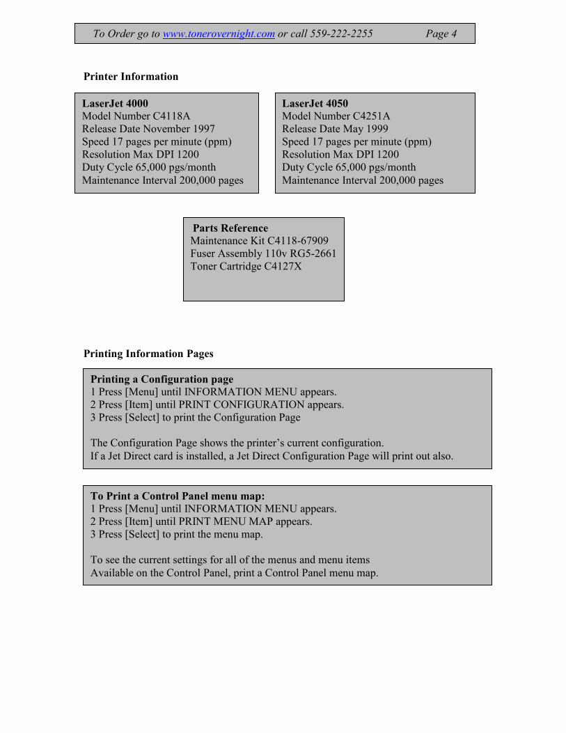
Printer Information
Printing Information Pages
LaserJet 4050
Model Number C4251A
Release Date May 1999
Speed 17 pages per minute (ppm)
Resolution Max DPI 1200
Duty Cycle 65,000 pgs/month
Maintenance Interval 200,000 pages
LaserJet 4000
Model Number C4118A
Release Date November 1997
Speed 17 pages per minute (ppm)
Resolution Max DPI 1200
Duty Cycle 65,000 pgs/month
Maintenance Interval 200,000 pages
Parts Reference
Maintenance Kit C4118-67909
Fuser Assembly 110v RG5-2661
Toner Cartridge C4127X
Printing a Configuration page
1 Press [Menu] until INFORMATION MENU appears.
2 Press [Item] until PRINT CONFIGURATION appears.
3 Press [Select] to print the Configuration Page
The Configuration Page shows the printer’s current configuration.
If a Jet Direct card is installed, a Jet Direct Configuration Page will print out also.
To Print a Control Panel menu map:
1 Press [Menu] until INFORMATION MENU appears.
2 Press [Item] until PRINT MENU MAP appears.
3 Press [Select] to print the menu map.
To see the current settings for all of the menus and menu items
Available on the Control Panel, print a Control Panel menu map.
To Order go to www.tonerovernight.com or call 559-222-2255 Page 4

To print an Event Log:
1 Press [Menu] until INFORMATION MENU appears.
2 Press [Item] until PRINT EVENT LOG appears.
3 Press [Select] to print the event Log.
The Event Log retains the printer’s last 30 error messages.
To Order go to www.tonerovernight.com or call 559-222-2255 Page 5
PRINT PAPER PATH TEST
1 Press [Menu] until PRINT PAPER PATH TEST appears.
2 Press [Item] Choose the input tray, output bin, duplexer (if available), and number of
copies.
3 Press [Select] to print the PRINT PAPER PATH TEST
The paper path test is a great tool. Test specific trays for paper jam problems, test
intermittent image problems or anything you can think of.
Paper Jam Related Problems - Error 13.xx
The number(s) after 13 indicate where the jam is occurring. This can be wrong. There
are many paper jam problems at the feed area. (From the tray) If printer has more than
one tray, use the same troubleshooting approach.
Tip: To determine where the paper is jamming, print one at a time until it jams. This will
be the problem area to focus. If you print a multi page job you won’t know where to
start. With paper feed problems I am organizing them in order of what happens more
often.
Problem: Jamming from Tray 2 and 3
Solution: Replace Feed Rollers. PN- Tray 2&3 Feed/Separation Roller RF5-1885
Symptom:
a.) Paper folded under in the middle of paper the width of the Feed/Separation roller.
b.) Buzzing noise when pulling from tray.
c.) Rollers are slick with little to no tread left.
d.) Intermittent jamming in the exit on large print jobs can actually be caused by worn
feed rollers intermittently not pulling from paper tray.
Note: Instructions for replacing the rollers are in the Maintenance Kit Installation
Instruction section
Problem: Multi-feeding/Jamming from Tray 2 & 3 (pulling more than one sheet at a
time)
Solution: Replace Feed and Separation rollers P/N RF5-1885, Replace Separation
Clutch P/N RB1-8974
Symptom: a.) If you have replaced paper tray feed and separation rollers and it is still has a
buzzing noise when pulling from the paper tray replace separation clutch.
b.) Multi-feeding can be caused by a bad clutch.
Problem: Jamming at paper tray 2 & 3.
Note: These rarely should be replaced and they don’t come in the maintenance kit.
Clean with 409 cleaner
Solution: Replace Tray 2 & 3 Pickup Rollers 4 rollers each tray RB1-8865/RB1-
8957or Tray 2 & 3 Pickup Roller Assembly 4 rollers with shaft RF5-2484
To Order go to www.tonerovernight.com or call 559-222-2255 Page 6
Problem: Jamming/multi-feeding from Tray 1 (pulling more than one sheet at a time)
Solution: Replace Tray 1 Pickup Roller RG5-3718 and Separation Pad RG5-5281.
Note: You can replace just the pad if the new style has been installed. You can tell
the old style if it is all one piece. The new style pad comes off of the separation pad
assembly.
Problem: Paper Jamming Tray 2 and 3. Paper tray springs are not pushing paper up
all the way.
Solution: Check tray with paper loaded. Inspect both sides. The paper should be
pushing on the metal tabs, one on each side (chrome triangular tabs). If not there may
be something under the plate that the paper sits on or the springs have been
compressed and need to be stretched.
Problem: 41.3 unexpected paper size
Solution: Make sure that all trays are correctly adjusted for size. Print a configuration
page and if the configuration page says it is different from what you have it set for
then replace RG5-2673-000CN 1 Feeder Controller PCA for the 500 sheet tray. RG5-
2685-000CN 1 Feeder, Control PCA for the 250 sheet feeder
Problem: 13.6 jamming in the Fuser, Paper stopped at Fuser.
Solution: Replace Fuser Assembly.
Tip: Remove fuser assembly and check that the exit sensor is snapped into the frame
of the fuser and the lever swings freely.
To Order go to www.tonerovernight.com or call 559-222-2255 Page 7
Problem: Jamming from Tray 1
After you have tried replacing tray 1 Pickup Roller RG5-3718 and Separation Pad
RG5-5281 and you are still having problems.
Solution: Replace RG5-2655-100CN 1 Tray 1 Pickup Assembly

Fuser Related Issues
Problem: Fuser Error 50.x A Fuser error has occurred.
Notes: X is the Description:
1 = Low Fuser temperature 2 = Fuser warm up service 3 = High Fuser temperature
4 = Low/Bad line voltage. (Printer hooked up to UPS uninterruptible power supply)
5 = Inconsistent Fuser
Solution: Replace Fuser Assembly, 110v P/N RG5-2661
I have had loose connectors so make sure nothing is loose. Replace the engine control
Board P/N Engine Controller Board RG5-3693-000CN (110V)
RG5-3694-000CN (220V)
Tip: 99% of the time the solution is to replace the Fuser Assembly. If you want to
know for sure follow the procedure for measuring the point to point readings in the
service guide.
Image Related Problems “Fuser”
If you have followed the procedure for determining image related problems then you
have determined that the problem is in the fuser assembly.
Problem: Lines running down the length of the page. Print rubs off
Solution: Replace the Fuser Assembly, 110v P/N RG5-2661
Tip: A common problem is lines on the edge of the page. Rub it with your hand and
you will feel the print rubbing off. This is a quick way to solve a fuser problem
To Order go to www.tonerovernight.com or call 559-222-2255 Page 8
Image Related Problems:
Image problems and print quality problems are mostly either a toner cartridge problem or
a fuser assembly problem. The quickest way to determine the solution is to replace the
toner cartridge. If you don’t have a toner cartridge to test it there is a procedure you can
use to make sure what the problem is.
Problem: lines, dark prints, light prints, streaks
Procedure for determining image related problems. a.) Place paper in tray 1.
b.) Print from tray 1.
c.) Stop machine (turn off) when page has fed past toner and just starts going into
the fuser.
d.) Carefully remove the toner cartridge
e.) Carefully remove the printed page. You should have a partially printed page
that is not fused. If the image defect is on the page the problem is in the toner
cartridge.
Solution: Replace the toner cartridge. If you eliminated the fuser assembly and the
problem still persists after you changed the toner cartridge, go to the next step.
Problem: light prints across the whole page
Solution: a.) Check and turn off EconoMode.
b.) Replace transfer roller P/N Transfer Roller RG5-4283
Problem: light prints on a portion of the page
Solution: Clean the scanner.
Tip: When the scanner is dirty it will never be light across the whole page. It will be
light on one side or in the middle. First replace the toner cartridge and if the pages are
still partially blank or light it is a dirty scanner.
*See my article on cleaning the scanner on HP laser printers.
To Order go to www.tonerovernight.com or call 559-222-2255 Page 9

Network Related Issues
Problem: Network card problems, 8X.YYYY or 40 EIO X Bad Transmission
Note: Print a Configuration Page.
Solution: a.) Does the EIO page print? If not reseat/replace Jet direct card
b.) If it prints the EIO page check the IP address.
To Order go to www.tonerovernight.com or call 559-222-2255 Page 10

Setting the IP Address
If the printer contains an HP JetDirect Card print server EIO card (HP for network card),
you can configure basic networking parameters using the EIO Menu. These and other
parameters can also be configured through HP JetAdmin.
1 Press [Menu] until EIO Menu appears.
2 Press [Item] Choose the input tray, output bin, duplexer (if available), and number of
copies.
3 Press [Select] to print the PRINT PAPER PATH TEST
CFG NETWORK=NO NO: The JetDirect Menu is not accessible.
CFG NETWORK=YES YES: The JetDirect Menu appears.
CFG TCP/IP=NO
NO: The TCP/IP Menu is not accessible.
CFG TCP/IP=YES
YES: The TCP/IP Menu appears.
In the TCP/IP Menu, you can specify BOOTP=YES for TCP/IP parameters to be
automatically loaded from a bootp or DHCP server when the printer is turned on.
If you specify BOOTP=NO, you can manually set selected TCP/IP parameters from the
Control Panel.
You can manually set each byte of the
●IP address (IP)
●Subnet Mask (SM),
●Syslog Server (LG),
●Default Gateway (GW).
Also, you can manually set the Timeout time period.
Note: If no IP address is assigned within the first 5 minutes, the HP JetDirect print server
card will assume a default IP address of 192.0.0.192.
To Order go to www.tonerovernight.com or call 559-222-2255 Page 11

ERROR CODES for Hewlett Packard LaserJet 4000/4050
13. XX PAPER JAM [LOCATION] Paper is jammed at the specified location
13.1 PAPER JAM 13.1 Paper delay jam at paper feed area.
13.2 PAPER JAM 13.2 Paper stopped jam at paper feed area.
13.5 PAPER JAM Paper delay jam at Fuser.
13.6 PAPER JAM 13.6 Paper stopped jam at Fuser.
13.10 PAPER JAM Paper delay jam at paper reversing area, Jammed at Duplexor.
13.22 PAPER JAM Paper delay jam at paper reversing area, Jammed at Duplexor.
13.20 PAPER JAM Paper stopped jam in the paper path. Check the entire paper path
13.21 PAPER JAM Top open jam
13.32 PAPER JAM Paper stopped jam in the paper path.
13.33 PAPER JAM Top open Jam
20 INSUFFICIENT MEMORY alternates with PRESS GO TO CONTINUE
21 PAGE TOO COMPLEX alternates with PRESS GO TO CONTINUE
22 EIO X BUFFER OVERFLOW alternates with PRESS GO TO CONTINUE
22 PARALLEL I/O BUFFER OVERFLOW alternates with PRESS GO TO
CONTINUE
22 SERIAL I/O BUFFER OVERFLOW alternates with PRESS GO TO CONTINUE
40 BAD SERIAL TRANSMISSION alternates with PRESS GO TO CONTINUE
40 EIO X BAD TRANSMISSION alternates with PRESS GO TO CONTINUE
41.3 UNEXPECTED PAPER SIZE
41. X PRINTER ERROR alternates with PRESS GO TO CONTINUE
50. X FUSER ERROR A Fuser error has occurred.
51. X PRINTER ERROR A loss of beam detect occurred.
52. X PRINTER ERROR The Laser Scanner speed is incorrect.
53. XY.ZZ PRINTER ERROR
55 PRINTER ERROR An internal communications error occurred.
56. X PRINTER ERROR A temporary printing error occurred.
57. X PRINTER ERROR An error occurred with the Fan’s motor.
59. X PRINTER ERROR A printing error occurred.
62. X PRINTER ERROR There is a problem with the printer’s memory.
64. X PRINTER ERROR A scan buffer error occurred.
66. XX.YY FINISHER/STAPLER STACKER FAILURE
66. XX.YY INPUT DEVICE FAILURE
66. XX.YY OUTPUT DEVICE FAILURE
68 NVRAM ERROR CHECK SETTINGS
69. X PRINTER ERROR A temporary printing error occurred.
79. XXXX PRINTER ERROR
8X.YYYY The EIO accessory in slot
To Order go to www.tonerovernight.com or call 559-222-2255 Page 12
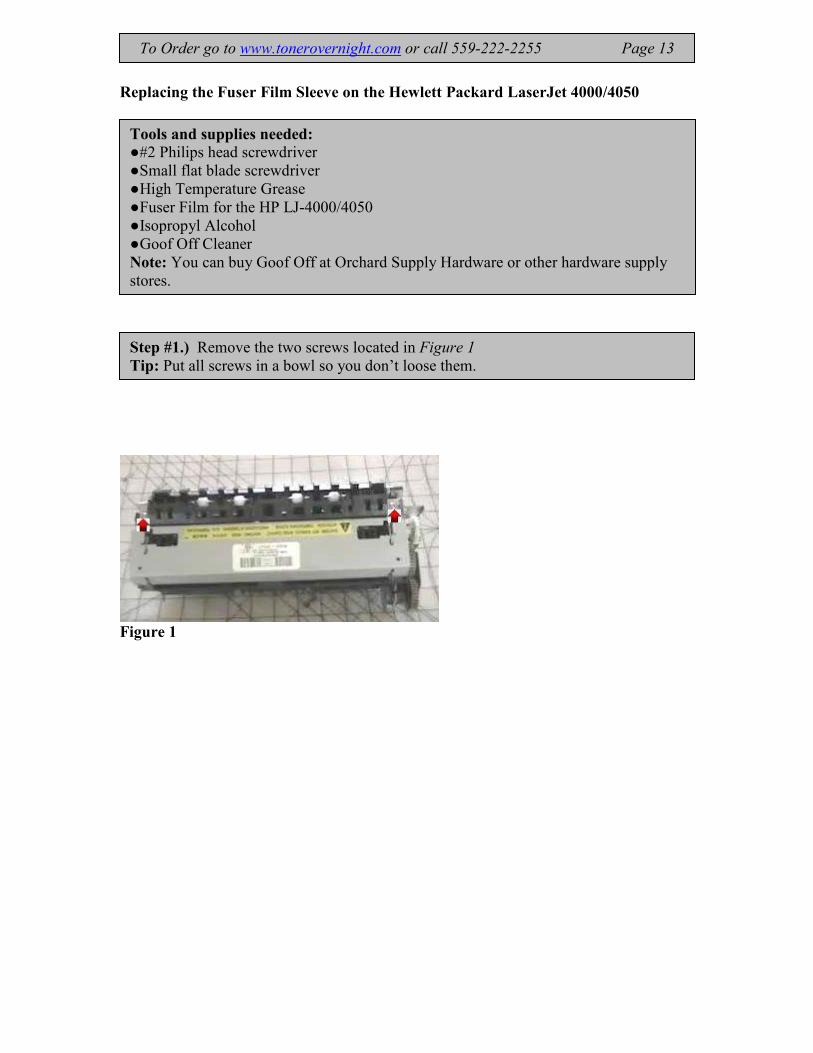
Replacing the Fuser Film Sleeve on the Hewlett Packard LaserJet 4000/4050
Figure 1
Step #1.) Remove the two screws located in Figure 1
Tip: Put all screws in a bowl so you don’t loose them.
Tools and supplies needed:
●#2 Philips head screwdriver
●Small flat blade screwdriver
●High Temperature Grease
●Fuser Film for the HP LJ-4000/4050
●Isopropyl Alcohol
●Goof Off Cleaner
Note: You can buy Goof Off at Orchard Supply Hardware or other hardware supply
stores.
To Order go to www.tonerovernight.com or call 559-222-2255 Page 13

Figure 2
Figure 3 Caution: Be careful not to damage sensor.
Step #2.)
Remove the cover by using a flat blade screwdriver and prying the latches outward
See Figure 2 and 3
To Order go to www.tonerovernight.com or call 559-222-2255 Page 14

Figure 4
Figure 5
Step #3.)
Pull off the cover and set aside. Be careful not to knock off the springs on either side:
See Figure 4
Step #4.)
Remove the end plate on the gear side.
Note: Some 4000 series fusers have 3 screws.
See figure 5
To Order go to www.tonerovernight.com or call 559-222-2255 Page 15

Figure 6
Step #5.)
Remove all of the gears.
See Figure 6
Remove the white gear by prying on clip with the flat blade screwdriver. Stack all of
the gears so you know how they go back on.
Note: The exit roller shaft has a bushing that has a slot that must be in the groove or
the white gear will not snap on.
To Order go to www.tonerovernight.com or call 559-222-2255 Page 16
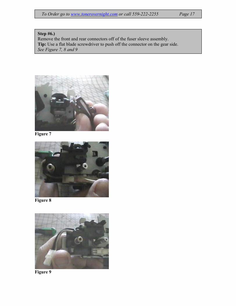
Figure 7
Figure 8
Figure 9
Step #6.)
Remove the front and rear connectors off of the fuser sleeve assembly.
Tip: Use a flat blade screwdriver to push off the connector on the gear side.
See Figure 7, 8 and 9
To Order go to www.tonerovernight.com or call 559-222-2255 Page 17

Figure 10
Figure 11 End Grommet
Step #7.)
Remove the fuser film sleeve assembly by pulling up and out.
Step #8.)
Remove the left side grommet as shown in figure10 and 11
To Order go to www.tonerovernight.com or call 559-222-2255 Page 18

Figure 12
Step #9.)
Remove the fuser film off of the sleeve by sliding it to the left.
See figure 12
To Order go to www.tonerovernight.com or call 559-222-2255 Page 19
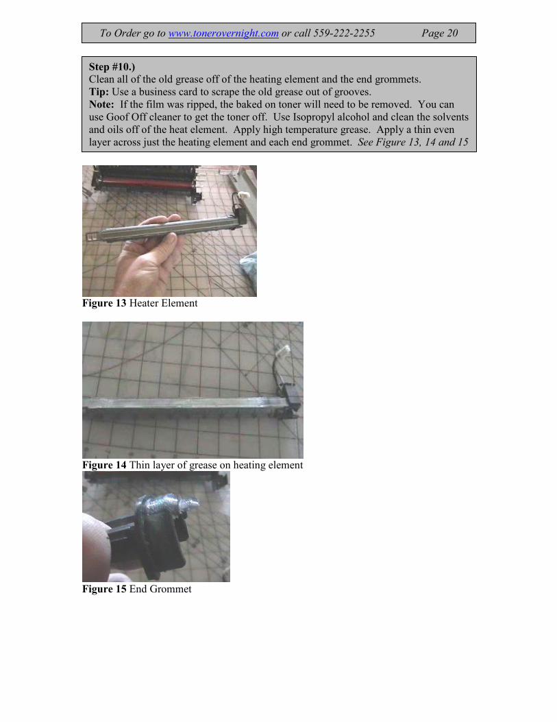
Figure 13 Heater Element
Figure 14 Thin layer of grease on heating element
Figure 15 End Grommet
Step #10.)
Clean all of the old grease off of the heating element and the end grommets.
Tip: Use a business card to scrape the old grease out of grooves.
Note: If the film was ripped, the baked on toner will need to be removed. You can
use Goof Off cleaner to get the toner off. Use Isopropyl alcohol and clean the solvents
and oils off of the heat element. Apply high temperature grease. Apply a thin even
layer across just the heating element and each end grommet. See Figure 13, 14 and 15
To Order go to www.tonerovernight.com or call 559-222-2255 Page 20
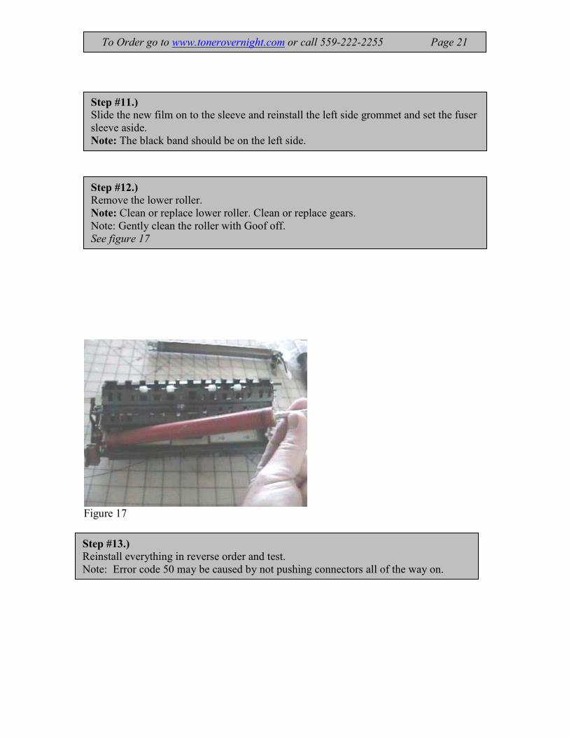
Figure 17
Step #11.)
Slide the new film on to the sleeve and reinstall the left side grommet and set the fuser
sleeve aside.
Note: The black band should be on the left side.
Step #12.)
Remove the lower roller.
Note: Clean or replace lower roller. Clean or replace gears.
Note: Gently clean the roller with Goof off.
See figure 17
Step #13.) Reinstall everything in reverse order and test.
Note: Error code 50 may be caused by not pushing connectors all of the way on.
To Order go to www.tonerovernight.com or call 559-222-2255 Page 21

Cleaning the Scanner, HP LaserJet 4000/4050
LJ-4000/4050 Scanner
To Order go to www.tonerovernight.com or call 559-222-2255 Page 22
Tools needed:
#2 Phillips head screw driver, Needle nose pliers, and small flat blade screw driver, Q-
tip.
Estimated Time of repair: 30 minutes
This article shows how to clean the scanner on all Hewlett Packard 4000 series Laser
Printers. This procedure needs to be done when the machine is in a dirty environment
and the dust builds up on the mirror inside the scanner.
Symptoms of a dirty scanner: Light prints even after you have tried a new toner
cartridge. Mostly shows itself as light prints on one side of prints or streaks or wide
blank lines.
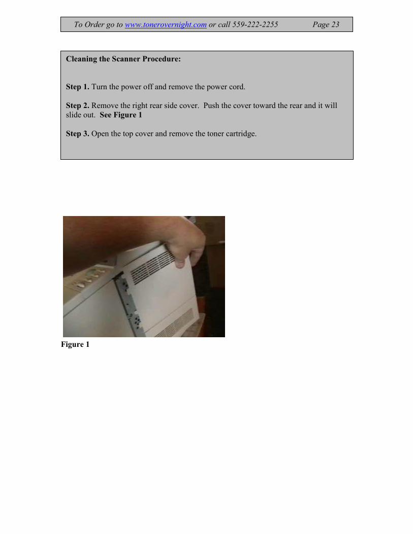
Figure 1
To Order go to www.tonerovernight.com or call 559-222-2255 Page 23
Cleaning the Scanner Procedure:
Step 1. Turn the power off and remove the power cord.
Step 2. Remove the right rear side cover. Push the cover toward the rear and it will
slide out. See Figure 1
Step 3. Open the top cover and remove the toner cartridge.
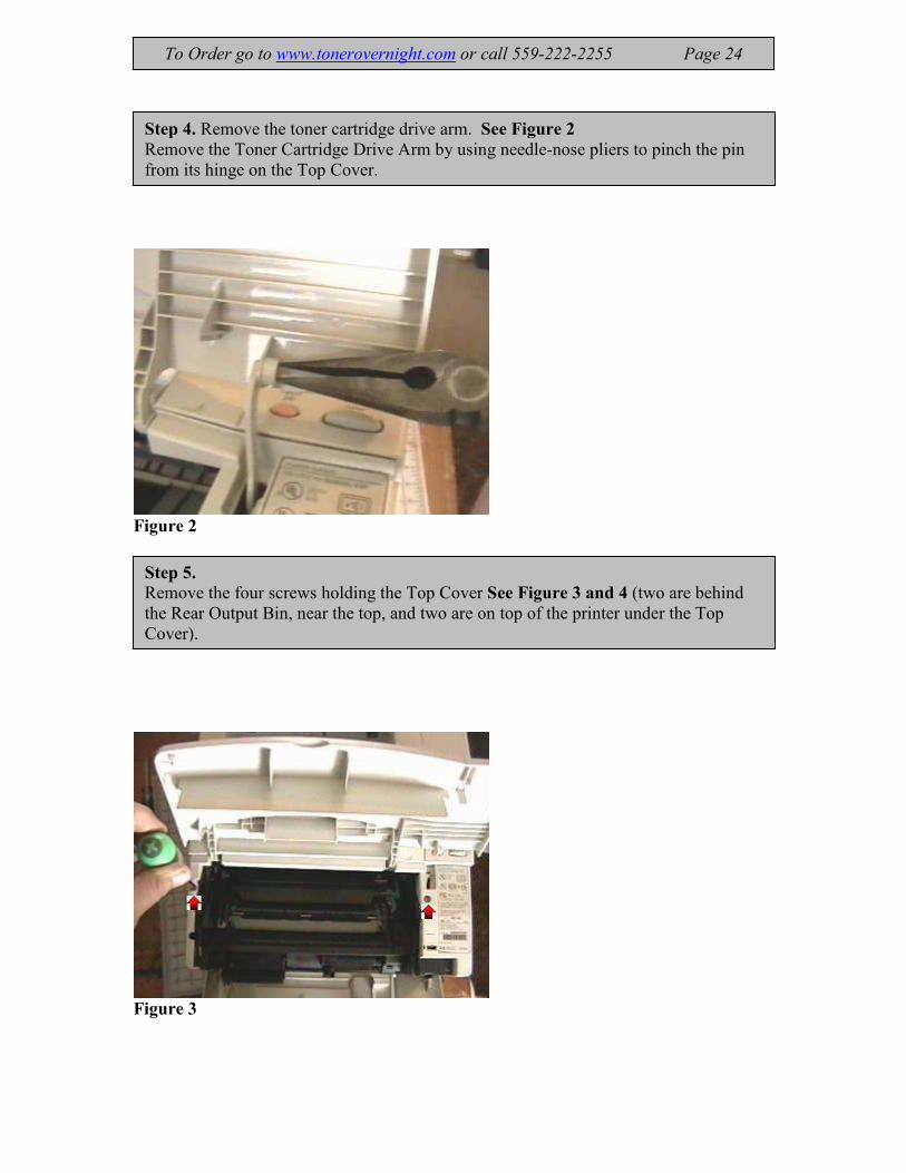
Figure 2
Figure 3
Step 4. Remove the toner cartridge drive arm. See Figure 2
Remove the Toner Cartridge Drive Arm by using needle-nose pliers to pinch the pin
from its hinge on the Top Cover.
Step 5. Remove the four screws holding the Top Cover See Figure 3 and 4 (two are behind
the Rear Output Bin, near the top, and two are on top of the printer under the Top
Cover).
To Order go to www.tonerovernight.com or call 559-222-2255 Page 24

Figure 4
To Order go to www.tonerovernight.com or call 559-222-2255 Page 25
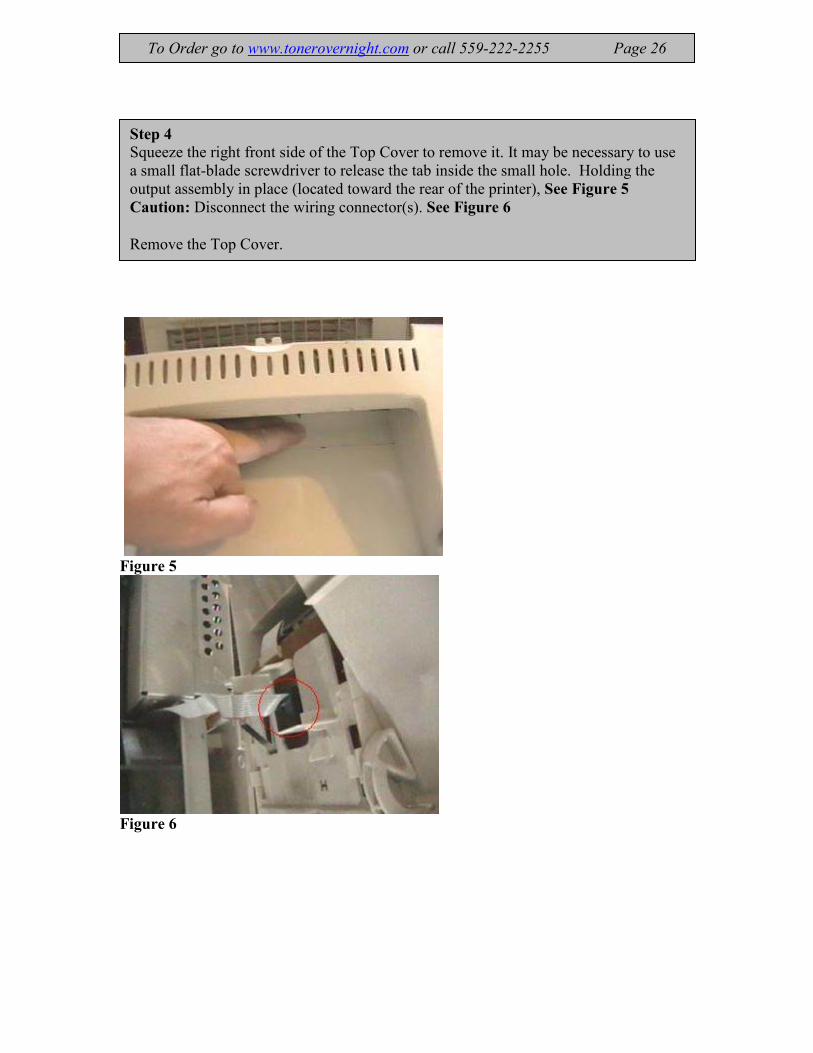
Figure 5
Figure 6
Step 4 Squeeze the right front side of the Top Cover to remove it. It may be necessary to use
a small flat-blade screwdriver to release the tab inside the small hole. Holding the
output assembly in place (located toward the rear of the printer), See Figure 5
Caution: Disconnect the wiring connector(s). See Figure 6
Remove the Top Cover.
To Order go to www.tonerovernight.com or call 559-222-2255 Page 26

Figure 7
Figure 8
Remove output assembly.
Facing the rear, pull up brass arm on the left side straight up. See Figure 7
Pry the white tab on the right side See Figure 8 and pull the output assembly up and
out.
Caution: Be careful of the sensor flag. When reinstalling make sure it rotates freely.
To Order go to www.tonerovernight.com or call 559-222-2255 Page 27
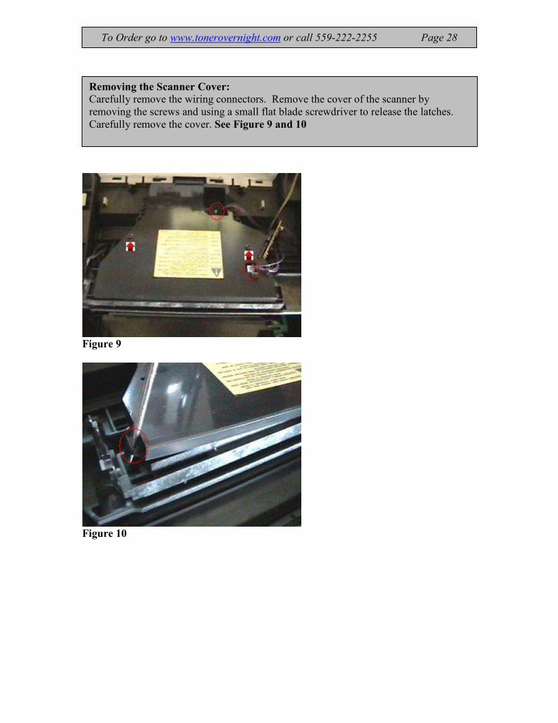
Figure 9
Figure 10
Removing the Scanner Cover:
Carefully remove the wiring connectors. Remove the cover of the scanner by
removing the screws and using a small flat blade screwdriver to release the latches.
Carefully remove the cover. See Figure 9 and 10
To Order go to www.tonerovernight.com or call 559-222-2255 Page 28
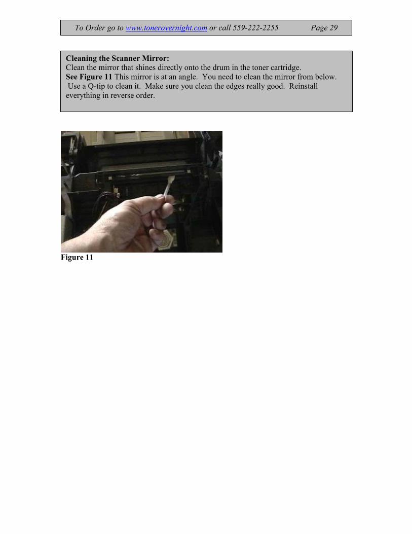
Figure 11
Cleaning the Scanner Mirror:
Clean the mirror that shines directly onto the drum in the toner cartridge.
See Figure 11 This mirror is at an angle. You need to clean the mirror from below.
Use a Q-tip to clean it. Make sure you clean the edges really good. Reinstall
everything in reverse order.
To Order go to www.tonerovernight.com or call 559-222-2255 Page 29

Installing HP Maintenance Kits the Right Way
There is always a right way and a wrong way with anything that you do. Installing a
maintenance kit in your HP Laser printer is one of them.
HP maintenance kits can be simple to install but many people are missing the service part
of the installation. Just installing the kit will keep you up and running, but there is much
more involved than just slapping in the components. A maintenance kit normally
consists of a fuser assembly, transfer roller, and feed rollers. When replacing the items in
the maintenance kit there are other service procedures that need to be accomplished as
well. There are many different models of HP Laser Printers. I have combined all of them
together for this article and may speak broadly on the specific issues or procedures I list.
First, you will need to vacuum out the residual paper and toner dust. This dust can find
its way into the drum and fuser and cause undue wear on the drum and drum blade inside
the toner cartridge. It can also cause wear on the fuser film or rollers in the fuser
assembly. It is important to vacuum it all out.
Remove all of the components listed.
Remove the fuser assembly, paper trays, feed rollers, toner cartridge, and the transfer
roller. Locate the jam area before the transfer roller. There is normally a green handle to
lift up. If you make many prints you will see a great deal of paper dust under this area.
Also, when you pull out the transfer roller, there will be toner and paper dust there also.
Make sure you vacuum out the paper dust inside the paper trays. Remove the paper from
the tray and you will not have any trouble finding paper dust. Some laser printers have a
circulation fan that has a filter. These will get completely clogged with dust and can
overheat the inside of the machine. This can cause many problems especially with the
toner cartridge. Look for vents on the side of the machine.
Warning: Do not use canned air! This will just blow the contaminates into the circuit
boards, bearings, and other components.
The next thing to do would be to wipe out the inside with a good towel. You can’t get all
of the toner and dust off with a vacuum. Toner tends to build up if not cleaned and it will
eventually cause many problems. Make sure you clean the entire paper path good.
Warning: There may be a sensor lever that sticks up and you could break one while
cleaning it if you are not careful.
To Order go to www.tonerovernight.com or call 559-222-2255 Page 30
Not all of the paper feed rollers are provided in a standard maintenance kit. There are
rollers that do not require replacement most of the time and they are known as the pre-
feed rollers. Pre-feed rollers are the rollers that push the paper into the feed rollers. They
don’t wear as much but they do require cleaning. You can clean the rollers with WD-40.
Just saturate the cloth and go over the tread of the roller really good. Then go back over
them with the dry part of the cloth and remove any residual cleaner.
Warning: Never use alcohol when cleaning feed rollers. Alcohol will dry out the tread
and ruin them!
Install all of the maintenance kit components. Be careful not to damage the fuser
assembly while unpacking. There are some fragile sensor arms and other components
that break easy on most of them. When you are done with installing all of the parts, you
should clean the outside covers. This is important to me because I want it to look good
when I am done. You can use 409 because it really cleans covers well and is easy to get
and it is inexpensive. Follow the procedure for resetting the Perform Maintenance
Display. Print out a test from your work station and you are finally done. If you follow
these steps each time you change your maintenance kit you will see a big difference in
quality and performance of your HP Laser Printer.
To Order go to www.tonerovernight.com or call 559-222-2255 Page 31
HP LaserJet 4000 and 4050 Series Printer
Maintenance Kit Installation Instructions
To Order go to www.tonerovernight.com or call 559-222-2255 Page 32
Step 1: Fuser assembly
1. Turn the printer off.
2. Unplug the printer.
WARNING: To avoid minor burns, wait 30 minutes for the fuser to
cool before continuing with this procedure.
3. Remove the duplexer if installed. If it is not installed, remove the two
duplexer slot covers by pulling away from the first.
Figure 1: Removing the left and right duplex connector covers
4. Turn the printer so its rear cover faces forward. Open and extend the
rear output bin.
Figure 2: Removing the rear cover/rear output bin
5. Flex the tray slightly to remove one side at a time
6. Loosen the two screws in the fuser assembly.
Figure 3: Loosening the captive screws for the fuser
7. Grasp the sides of the fuser assembly and pull it out of the printer.
NOTE: When removing the fuser, the plastic cover can come off with
the fuser remaining in the printer.
8. Install the new fuser assembly (align the left side first). Push the fuser
assembly into the printer until the two tabs on both sides of the fuser
assembly press against the plastic on the printer.
9. Replace the two screws. (Turn the screws counterclockwise until they
click, then turn them clockwise to tighten.)
10. Replace the tray, inserting one side at a time.
11. Replace the duplexer slot covers or the duplexer.
12. Continue with the next section to remove and replace the transfer roller.
NOTE: The printer will not reset the maintenance counter back to 0 until
it reaches 200,000 pages. See: Resetting maintenance count before perform printer
maintenance message is displayed.
Required tools
· Phillips #2 screwdriver
· Flat-blade screwdriver

Figure 1:
Figure 2:
Figure 3:
To Order go to www.tonerovernight.com or call 559-222-2255 Page 33

Figure 4
Step 2: Transfer roller
1. Put on gloves.
CAUTION: To avoid damaging the transfer roller, never touch the
transfer roller with bare hands.
2. Turn the printer so the front is facing forward.
Figure 4: Removing the transfer roller
3. Open the top-cover and remove the toner cartridge. The transfer roller
is underneath the toner cartridge. See Figure 4
CAUTION: Do not touch the black rubber part of the roller. Skin
oils on the roller can cause problems with print quality.
4. Using a flat-blade screwdriver, pry the right end of the metal shaft out of
place, then the left end.
NOTE: When the transfer roller is replaced, make sure the black collar
is oriented properly, with the open end down.
5. Continue with the next section to remove and replace the Tray 1 pickup
roller.
To Order go to www.tonerovernight.com or call 559-222-2255 Page 34
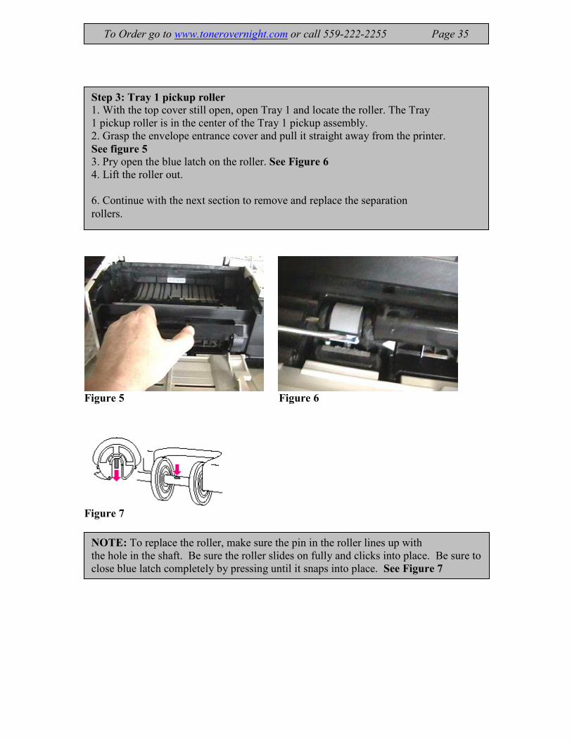
Figure 5 Figure 6
Figure 7
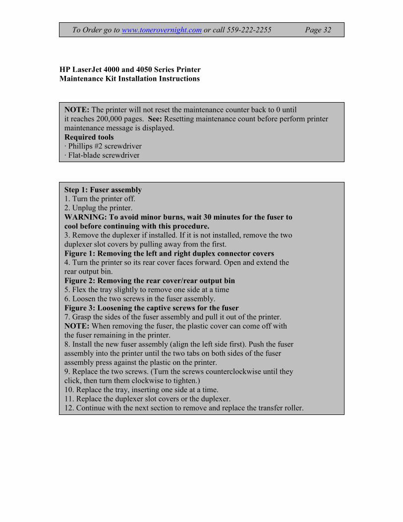
Step 3: Tray 1 pickup roller
1. With the top cover still open, open Tray 1 and locate the roller. The Tray
1 pickup roller is in the center of the Tray 1 pickup assembly.
2. Grasp the envelope entrance cover and pull it straight away from the printer.
See figure 5 3. Pry open the blue latch on the roller. See Figure 6
4. Lift the roller out.
6. Continue with the next section to remove and replace the separation
rollers.
To Order go to www.tonerovernight.com or call 559-222-2255 Page 35
NOTE: To replace the roller, make sure the pin in the roller lines up with
the hole in the shaft. Be sure the roller slides on fully and clicks into place. Be sure to
close blue latch completely by pressing until it snaps into place. See Figure 7

Figure 8
Step 4: Separation rollers
NOTE: Remove and replace the separation rollers and feed rollers on
all trays except Tray 1.
1. Remove the tray. Open the door on the left, inside front of the tray.
Removing the separation rollers
NOTE: The separation rollers are inside the paper trays.
2. Release the latch and lift the cover inside the tray. Figure 8:
3. Pinch the release at the left side of the roller and slide it off the shaft. Figure 9
4. Replace new roller by sliding it on the shaft. Replace the cover.
CAUTION: Be sure that the roller slides on fully and clicks into
place. Be sure to close cover completely by pressing until it snaps
into place.
Replacing Tray 2 and 3 Separation Clutch
If jamming and multi-feeding continues replace the separation clutch see Figure 10
5. Continue with the next section to remove and replace the feed roller.
To Order go to www.tonerovernight.com or call 559-222-2255 Page 36
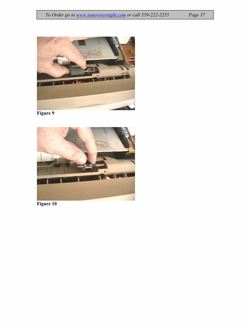
Figure 9
Figure 10
To Order go to www.tonerovernight.com or call 559-222-2255 Page 37

Figure 11
Step 5: Feed rollers
1. Move the printer to the edge of the work area for access to the feed
roller area.
NOTE: The following procedure is the same for all HP LaserJet 4000
series printers; there are two (2) rollers for the HP LaserJet 4000t and
4000tn and one roller for the HP LaserJet 4000 and 4000n.
Figure 7: Removing the paper feed rollers (HP LaserJet 4000t and 4000tn
shown)
2. Remove the tray from the feeder. The paper feed roller's are inside the
feeder.
3. Pinch the release at the left side of the roller and slide it off the shaft. Figure 11
4. Line up the new roller with the flat part of the axle. Slide the roller onto
the axle and rotate until it locks into place.
5. Continue with the next section to reset the maintenance page count.
To Order go to www.tonerovernight.com or call 559-222-2255 Page 38

.
Figure 11
Step 6: Reset the maintenance page count
When all of the previous steps are complete, reset the maintenance page
count.
To reset the maintenance page count:
Press and hold down the left side of the ITEM and VALUE buttons on
the control panel while turning the printer on.
(The printer will not reset properly if the ITEM and VALUE buttons are held
down on the right side.)
RESET MAINT COUNT appears in the display, followed by INITIALIZING.
After a few seconds, READY will appear in the display. At this point, the
printer's maintenance count has been reset.
Replacing Tray 2 and 3 Pick up Rollers
Remove the toner cartridge power cord and network or parallel cable from machine.
Remove all paper trays. Tip machine on the fuser side so the paper feed is facing up
Push the white tab of each roller (4) and pull off rollers. See Figure 12
Install each roller in reverse order.
Tray 2 & 3 Pickup Roller order 4 per tray RB1-8865/RB1-8957
“Use highlighted P/N for updated rollers”
To Order go to www.tonerovernight.com or call 559-222-2255 Page 39

Replacing Tray 1 Separation Pad P/N - RG5-5281
Figure 1 Figure 2
Figure 3 Figure 4
To Order go to www.tonerovernight.com or call 559-222-2255 Page 40
Step #1. Remove Tray 1 pickup roller
The Tray 1 pickup roller is in the center of the Tray 1 pickup assembly.
Grasp the envelope entrance cover and pull it away from the printer.
See figure 1 Pry open the blue latch on the roller.
Lift the roller out. See Figure 2
Step #2. Remove the front cover from tray 1.
Push outward on the two plastic hinges.
Caution: Be careful not to break the hinges.
Slide the cover to the right and remove it from the three bottom hinges. See Figure 3
Pull off tray 1 sensor arm cover and remove tray 1 by rotating it downward.
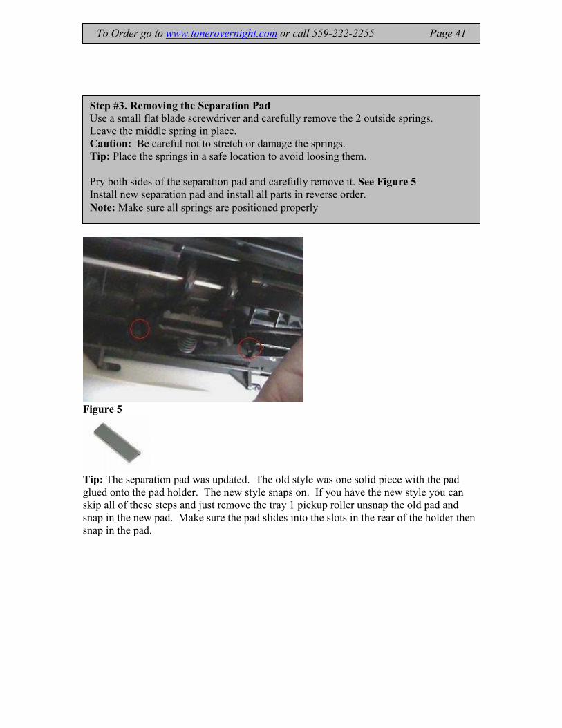
Figure 5
Tip: The separation pad was updated. The old style was one solid piece with the pad
glued onto the pad holder. The new style snaps on. If you have the new style you can
skip all of these steps and just remove the tray 1 pickup roller unsnap the old pad and
snap in the new pad. Make sure the pad slides into the slots in the rear of the holder then
snap in the pad.
Step #3. Removing the Separation Pad
Use a small flat blade screwdriver and carefully remove the 2 outside springs.
Leave the middle spring in place.
Caution: Be careful not to stretch or damage the springs.
Tip: Place the springs in a safe location to avoid loosing them.
Pry both sides of the separation pad and carefully remove it. See Figure 5
Install new separation pad and install all parts in reverse order.
Note: Make sure all springs are positioned properly
To Order go to www.tonerovernight.com or call 559-222-2255 Page 41
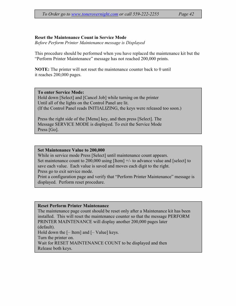
Reset the Maintenance Count in Service Mode Before Perform Printer Maintenance message is Displayed
This procedure should be performed when you have replaced the maintenance kit but the
“Perform Printer Maintenance” message has not reached 200,000 prints.
NOTE: The printer will not reset the maintenance counter back to 0 until
it reaches 200,000 pages.
To enter Service Mode:
Hold down [Select] and [Cancel Job] while turning on the printer
Until all of the lights on the Control Panel are lit.
(If the Control Panel reads INITIALIZING, the keys were released too soon.)
Press the right side of the [Menu] key, and then press [Select]. The
Message SERVICE MODE is displayed. To exit the Service Mode
Press [Go].
Reset Perform Printer Maintenance
The maintenance page count should be reset only after a Maintenance kit has been
installed. This will reset the maintenance counter so that the message PERFORM
PRINTER MAINTENANCE will display another 200,000 pages later
(default).
Hold down the [– Item] and [– Value] keys.
Turn the printer on.
Wait for RESET MAINTENANCE COUNT to be displayed and then
Release both keys.
Set Maintenance Value to 200,000
While in service mode Press [Select] until maintenance count appears.
Set maintenance count to 200,000 using [Item] +/- to advance value and [select] to
save each value. Each value is saved and moves each digit to the right.
Press go to exit service mode.
Print a configuration page and verify that “Perform Printer Maintenance” message is
displayed. Perform reset procedure.
To Order go to www.tonerovernight.com or call 559-222-2255 Page 42