Embed Size (px)
Citation preview

Guide to I/O System
20150716

Copyright © 20052016 SSAB EMEA AB
Permission is granted to copy, distribute and/or modify this document under the terms of the GNU Free Documentation License, Version 1.2 or any later version published by the Free Software Foundation; with no Invariant Sections, no FrontCover Texts, and no BackCover Texts.

Table of ContentsAbout this Guide ..................................................................................................................................8Introduction..........................................................................................................................................9Overview............................................................................................................................................10
Levels.............................................................................................................................................10Configuration.................................................................................................................................10
I/O System..........................................................................................................................................11PSS9000.........................................................................................................................................12
Rack objekt...............................................................................................................................12Rack_SSAB..........................................................................................................................12
Attributes.........................................................................................................................12Driver...............................................................................................................................12
Ssab_RemoteRack................................................................................................................12Attributes.........................................................................................................................12
Di cards.....................................................................................................................................13Ssab_BaseDiCard.................................................................................................................13Ssab_DI32D.........................................................................................................................13
Do cards....................................................................................................................................13Ssab_BaseDoCard................................................................................................................13Ssab_DO32KTS...................................................................................................................14Ssab_DO32KTS_Stall..........................................................................................................14
Ai cards.....................................................................................................................................14Ssab_BaseACard..................................................................................................................14Ssab_AI8uP..........................................................................................................................14Ssab_AI16uP........................................................................................................................15Ssab_AI32uP........................................................................................................................15Ssab_AI16uP_Logger..........................................................................................................15
Ao cards....................................................................................................................................15Ssab_AO16uP......................................................................................................................15Ssab_AO8uP........................................................................................................................15Ssab_AO8uPL......................................................................................................................15
Co cards.....................................................................................................................................15Ssab_CO4uP.........................................................................................................................15
Profibus..........................................................................................................................................17The Profibus configuator..........................................................................................................17
Address.................................................................................................................................18SlaveGsdData.......................................................................................................................18UserPrmData........................................................................................................................18Module..................................................................................................................................19
Specify the data area.................................................................................................................20Digital inputs........................................................................................................................20Analog inputs.......................................................................................................................21Digital outputs......................................................................................................................21Analog outputs.....................................................................................................................21Complex dataareas...............................................................................................................21
Driver........................................................................................................................................21Agent object..............................................................................................................................21

Pb_Profiboard.......................................................................................................................21Slave objects.............................................................................................................................21
Pb_Dp_Slave........................................................................................................................21ABB_ACS_Pb_Slave...........................................................................................................22Siemens_ET200S_IM151....................................................................................................22Siemens ET200M_IM153....................................................................................................22
Module objects..........................................................................................................................22Pb_Module...........................................................................................................................22ABB_ACS_PPO5.................................................................................................................22Siemens_ET200S_Ai2.........................................................................................................22Siemens_ET200S_Ao2........................................................................................................22Siemens_ET200M_Di4........................................................................................................22Siemens_ET200M_Di2........................................................................................................22Siemens_ET200M_Do4.......................................................................................................22Siemens_ET200M_Do2.......................................................................................................22
Profinet...........................................................................................................................................23The profinet configurator..........................................................................................................23
Network Settings..................................................................................................................24DeviceName....................................................................................................................24IP Address........................................................................................................................24Subnet mask.....................................................................................................................24MAC Address..................................................................................................................25SendClock........................................................................................................................25ReductionRatio................................................................................................................25Phase................................................................................................................................25
ByteOrdering........................................................................................................................25DeviceInfo............................................................................................................................25Device...................................................................................................................................25DAP......................................................................................................................................25Slot1 Slotx..........................................................................................................................25
ModuleType.....................................................................................................................26ModuleClass....................................................................................................................26ModuleInfo......................................................................................................................26Subslot X.........................................................................................................................26
Profinet viewer..........................................................................................................................27Agent object..............................................................................................................................28
PnControllerSoftingPNAK...................................................................................................28Device objects...........................................................................................................................28
PnDevice..............................................................................................................................28Siemens_ET200S_PnDevice................................................................................................28Siemens_ET200M_PnDevice..............................................................................................28Sinamics_G120_PnDevice...................................................................................................28ABB_ACS_PnDevice..........................................................................................................28
Module objects..........................................................................................................................28PnModule.............................................................................................................................28BaseFcPPO3PnModule........................................................................................................28Sinamics_Tgm1_PnModule.................................................................................................28Siemens_Ai2_PnModule......................................................................................................29Siemens_Ao2_PnModule.....................................................................................................29Siemens_Di4_PnModule......................................................................................................29

Siemens_Di2_PnModule......................................................................................................29Siemens_Do4_PnModule.....................................................................................................29Siemens_Do2_PnModule.....................................................................................................29Siemens_Do32_PnModule...................................................................................................29Siemens_D16_PnModule.....................................................................................................29Siemens_Do8_PnModule.....................................................................................................29Siemens_Di32_PnModule....................................................................................................29Siemens_Di16_PnModule....................................................................................................29Siemens_Di8_PnModule......................................................................................................29Siemens_Dx16_PnModule...................................................................................................29Siemens_Ai8_PnModule......................................................................................................30Siemens_Ao8_PnModule.....................................................................................................30Siemens_Ai4_PnModule......................................................................................................30Siemens_Ao4_PnModule.....................................................................................................30
Ethernet Powerlink........................................................................................................................31What Powerlink does................................................................................................................31Main features.............................................................................................................................31Powerlink facts..........................................................................................................................31Proview as a MN.......................................................................................................................32
openCONFIGURATOR (CDCfile)....................................................................................33Proview as a CN........................................................................................................................40Communication between two Proview nodes...........................................................................42
Modbus TCP Client.......................................................................................................................43Configuration of a device..........................................................................................................44
Master...................................................................................................................................44Slaves....................................................................................................................................44Modules................................................................................................................................45
Specify the data area.................................................................................................................46Example................................................................................................................................46
Master object.............................................................................................................................49Modbus_Master....................................................................................................................49
Slave objects.............................................................................................................................49Modbus_TCP_Slave.............................................................................................................49
Module objects..........................................................................................................................50Modbus_Module..................................................................................................................50
Modbus TCP Server.......................................................................................................................51Data areas..................................................................................................................................51Unit id.......................................................................................................................................51Port............................................................................................................................................51
Hilscher cifX..................................................................................................................................54SYCON.net configuration.........................................................................................................54cifX driver configuration..........................................................................................................55Proview configuration...............................................................................................................55
MotionControl USB I/O................................................................................................................58Driver........................................................................................................................................58Rack object................................................................................................................................58
MotonControl_USB.............................................................................................................58Card object................................................................................................................................59
MotionControl_USBIO........................................................................................................59Channels....................................................................................................................................59

Ai configuration...................................................................................................................59Ao configuration...................................................................................................................60
Link file.....................................................................................................................................60Velleman K8055............................................................................................................................61
Agent object..............................................................................................................................61USB_Agent..........................................................................................................................61
Rack object................................................................................................................................61Velleman_K8055..................................................................................................................61
Card object................................................................................................................................62Velleman_K8055_Board......................................................................................................62
Channels....................................................................................................................................62Ai configuration...................................................................................................................62Ao configuration...................................................................................................................62
Link file.....................................................................................................................................62Arduino Uno..................................................................................................................................64
Initialization of the Arduino board............................................................................................64USB port baud rate ...................................................................................................................65I/O Configuration......................................................................................................................65Rack object................................................................................................................................66
Arduino_USB.......................................................................................................................66Card object................................................................................................................................66
Arduino_Uno........................................................................................................................66Channels....................................................................................................................................66
GPIO..............................................................................................................................................69OneWire.........................................................................................................................................70
OneWire_AiDevice...................................................................................................................70Maxim_DS18B20.....................................................................................................................70
Adaption of I/O systems.....................................................................................................................72Overview........................................................................................................................................72
Levels........................................................................................................................................72Area objects...............................................................................................................................73I/O objects.................................................................................................................................73Processes...................................................................................................................................73Framework................................................................................................................................73Methods.....................................................................................................................................74
Framework.....................................................................................................................................74Create I/O objects..........................................................................................................................76
Flags..........................................................................................................................................78Attributes...................................................................................................................................79
Description...........................................................................................................................79Process..................................................................................................................................79ThreadObject........................................................................................................................79
Method objects..........................................................................................................................79Agents...................................................................................................................................80Racks....................................................................................................................................80Cards.....................................................................................................................................80Connectmethod for a ThreadObject....................................................................................80
Methods.........................................................................................................................................81Local data structure..............................................................................................................81AgentMethods.....................................................................................................................81

IoAgentInit.......................................................................................................................81IoAgentClose...................................................................................................................81IoAgentRead....................................................................................................................82IoAgentWrite...................................................................................................................82IoAgentSwap...................................................................................................................82Rackmetoder...................................................................................................................82IoRackInit........................................................................................................................82IoRackClose.....................................................................................................................82IoRackRead.....................................................................................................................82IoRackWrite.....................................................................................................................82IoRackSwap.....................................................................................................................82Cardmetoder...................................................................................................................83IoCardInit.........................................................................................................................83IoCardClose.....................................................................................................................83IoCardRead......................................................................................................................83IoCardWrite.....................................................................................................................83IoCardSwap.....................................................................................................................83
Method registration..............................................................................................................83Class registration..................................................................................................................83
Module in Proview base system......................................................................................83Project..............................................................................................................................84
Example of rack methods.....................................................................................................84Example of the methods of a digital input card....................................................................85Example of the methods of a digital output card..................................................................88
Step by step description.................................................................................................................91Attach to a project.....................................................................................................................91
Create classes.......................................................................................................................91Create a class volume......................................................................................................91Open the classvolume......................................................................................................92Create a rack class...........................................................................................................93Create a card class...........................................................................................................95Build the classvolume....................................................................................................101
Install the driver..................................................................................................................101Write methods.........................................................................................................................102
Class registration...........................................................................................................106Makefile.........................................................................................................................106Link file.........................................................................................................................107
Configure the node hierarchy.............................................................................................107

About this Guide
The Proview Guide to I/O System is intended for persons who will connect different kinds of I/O systems to Proview, and for users that will gain a deeper understanding of how the I/O handling or proview works. The first part is an overview of the I/O systems adapted to Proview, and the second part a description of how to adapt new I/O systems to Proview.

Introduction
The Proview I/O handling consists of a framework that is designed to
● be portable and runnable on different platforms.
● handle I/O devices on the local bus.
● handle distributed I/O systems and communicate with remote rack systems.
● make it possible to add new I/Osystems with ease.
● allow projects to implement local I/O systems.
● synchronize the I/Osystem with the execution of the plcprogram, or application processes.

Overview
The I/O devices of a process station is configured by creating objects in the Proview database. The objects are divided in two trees, the Plant hierarchy and the Node hierarchy.
The Plant hierarchy describes how the plant is structured in various process parts, motors, pumps, fans etc. Here you find signal objects that represents the values that are fetched from various sensors and switches, or values that are put out to motors, actuators etc. Signal objects are of the classes Di, Do, Ai, Ao, Ii, Io, Co or Po.
The node hierarchy describes the configuration of the process station, with server processes and I/O system. The I/O system is configured by a tree of agent, rack, card and channel objects. The channel objects represent an I/O signal attached to the computer at a channel of an I/O card (or via a distributed bus system). The channel objects are of the classes ChanDi, ChanDo, ChanAi, ChanAo, ChanIi, ChanIo and ChanCo. Each signal object in the plant hierarchy points to a channel object in the node hierarchy. The connection corresponds to the physical link between the sensor and the channel of a I/O unit.
LevelsThe I/O objects in a process station are configured in a tree structure with four levels: Agent, Rack, Card and Channel. The Channel objects can be configured as individual objects, or reside as internal attributes in a Card object.
ConfigurationWhen configuring an I/O system on the local bus, often the Rack and Cardlevels are sufficient. A configuration can look like this. A Rack object is placed below the $Node object, and below this a Card object for each I/O card that i installed in the rack. The card objects contains channel objects for the channels on the cards. The channel objects are connected to signal objects in the plant hierarchy. The Channels for analog signals contains attributes for measurement ranges, and the card objects contains attributes for addresses.
The configuration of a distributed I/O system is a bit different. Still the levels Agent, Rack, Card and Channel are used, but the levels has another meaning. If we take Profibus as an example, the agentlevel consist of an object for the master card that is mounted on the computer. The rack level consist of slave objects, that represent the Profibus slaves that are connected to the Profibus circuit. The card level consist of module objects that represent modules handled by the slaves. The Channel objects represent data sent on the bus from the master card to the modules or vice versa.

I/O System
This chapter contains descriptions of the I/O systems that are implemented in Proview.

PSS9000PSS9000 consist of a set of I/O cards for analog input, analog output, digital input and digital output. There are also cards for counters and PID controllers. The cards are placed in a rack with the bus QBUS, a bus originally designed for DEC's PDP11 processor. The rack is connected via a PCIQBUS converter to an x86 PC, or connected via Ethernet, so called Remoterack.
The system is configured with objects from the SsabOx volume. There are objects representing the Rack and Carde levels. The agent level i represented by the $Node object.
Rack objekt
Rack_SSAB
The Rack_SSAB object represents a 19” PSS9000 rack with QBUS backplane. The number of card slots can vary.
The rack is connected to a x86 PC with a PCIQBUS converter card, PCIQ, that is installed into the PC and connected to the rack with a cable. Several racks can be connected via bus extension card.
The rack objects are placed below the $Node objects and named C1, C2 etc (in older systems the naming convention R1, R2 etc can be found).
Attributes
Rack_SSAB doesn't contain any attributes used by the system.
Driver
The PCIQBUS converter, PCIQ, requires installation of a driver.
Ssab_RemoteRack
The Ssab_RemoteRack object configures a PSS9000 rack connected via Ethernet. A BFBETH card is inserted into the rack and connected Ethernet.
The object is placed below the $Node object and named E1, E2 etc.
Attributes
Attributes Description
Address ipadress for the BTBETH card.
LocalPort Port in the process station.
RemotePort Port for the BTBETH card. Default value 8000.
Process Process that handles the rack. 1 the plcprogram, 2 io_comm.

Attributes Description
ThreadObject Thread object for the plc thread that should handle the rack. Only used if Process is 1.
StallAction No, ResetInputs or EmergencyBreak. Default EmergencyBreak.
Di cardsAll digital input cards have a common base class, Ssab_BaseDiCard, that contains attributes common for all di cards. The objects for each card type are extended with channel objects for the channels of the card.
Ssab_BaseDiCard
Attributes Description
RegAddress QBUS address.
ErrorHardLimit Error limit that stops the system.
ErrorSoftLimit Error limit that sends an alarm message.
Process Process that handles the rack. 1 the plcprogram, 2 io_comm.
ThreadObject Thread object for the plc thread that should handle the rack. Only used if Process is 1.
ConvMask1 The conversion mask states which channels will be converted to signal values. Handles channel 1 – 16.
ConvMask2 See ConvMask1. Handles channel 17 – 32.
InvMask1 The invert mask states which channels are inverted. Handles channel 116.
InvMask2 See InvMask1. Handles channel 17 – 32.
Ssab_DI32D
The object configures a digital input card of type DI32D. The card has 32 channels, which channel objects reside as internal attributes in the object. The object is placed as a child to a Rack_SSAB or Ssab_RemoteRack object. Attributes, see BaseDiCard.
Do cardsAll digital output cards have a common base class, Ssab_BaseDoCard, that contains attributes that are common for all do cards. The objects for each card type are extended with channel objects for the channels of the card.
Ssab_BaseDoCard
Attributes Description
RegAddress QBUS address.
ErrorHardLimit Error limit that stops the system.
ErrorSoftLimit Error limit that sends an alarm message.

Attributes Description
Process Process that handles the rack. 1 the plcprogram, 2 io_comm.
ThreadObject Thread object for the plc thread that should handle the rack. Only used if Process is 1.
InvMask1 The invert mask states which channels are inverted. Handles channel 116.
InvMask2 See InvMask1. Handles channel 17 – 32.
FixedOutValue1 Bitmask for channel 1 to 16 when the I/O handling is emergency stopped. Should normally be zero.
FixedOutValue2 See FixedOutValue1. FixedOutValue2 is a bitmask for channel 17 – 32.
ConvMask1 The conversion mask states which channels will be converted to signal values. Handles channel 1 – 16.
ConvMask2 See ConvMask1. Handles channel 17 – 32.
Ssab_DO32KTS
The object configures a digital output card of type DO32KTS. The card has 32 output channels, whose DoChan objects are internal attributes in the card object. The object is positioned as a child to a Rack_SSAB or Ssab_RemoteRack object. Attributes, see BaseDoCard.
Ssab_DO32KTS_Stall
The object configures a digital output card of type DO32KTS Stall. The card is similar to DO32KTS, but also contains a stall function, that resets the bus, i.e. all outputs are zeroed on all cards, if no write or read i done on the card in 1.5 seconds.
Ai cardsAll analog cards have a common base class, Ssab_BaseACard, that contains attributes that are common for all analog cards. The objects for each card type are extended with channel objects for the channels of the card.
Ssab_BaseACard
Attribut Beskrivning
RegAddress QBUS address.
ErrorHardLimit Error limit that stops the system.
ErrorSoftLimit Error limit that sends an alarm message.
Process Process that handles the rack. 1 the plcprogram, 2 io_comm.
ThreadObject Thread object for the plc thread that should handle the rack. Only used if Process is 1.
Ssab_AI8uP
The object configures an analog input card of type Ai8uP. The card has 8 channels, whose AiChan objects are internal attributes in the card object. The object is positioned as a child to a Rack_SSAB or Ssab_RemoteRack object. Attributes, see BaseACard.

Ssab_AI16uP
The object configures an analog input card of type Ai16uP. The card has 16 channels, whose AiChan objects is internal attributes in the card object. The object is positioned as a child to a Rack_SSAB or Ssab_RemoteRack object. Attributes, see BaseACard.
Ssab_AI32uP
The object configures an analog input card of type Ai32uP. The card has 32 channels, whose AiChan objects are internal attributes in the card object. The object is positioned as a child to a Rack_SSAB or Ssab_RemoteRack object. Attributes, see BaseACard.
Ssab_AI16uP_Logger
The object configures an analog input card of type Ai16uP_Logger. The card has 16 channels, whose AiChan objects are internal attributes in the card object. The object is positioned as a child to a Rack_SSAB or Ssab_RemoteRack object. Attributes, see BaseACard.
Ao cards
Ssab_AO16uP
The object configures an analog input card of type AO16uP. The card has 16 channels, whose AoChan objects are internal attributes in the card object. The object is positioned as a child to a Rack_SSAB or Ssab_RemoteRack object. Attributes, see BaseACard.
Ssab_AO8uP
The object configures an analog input card of type AO8uP. The card has 8 channels, whose AoChan objects are internal attributes in the card object. The object is positioned as a child to a Rack_SSAB or Ssab_RemoteRack object. Attributes, see BaseACard.
Ssab_AO8uPL
The object configures an analog input card of type AO8uP. The card has 8 channels, whose AoChan objects are internal attributes in the card object. The object is positioned as a child to a Rack_SSAB or Ssab_RemoteRack object. Attributes, see BaseACard.
Co cards
Ssab_CO4uP
The object configures a counter card of type CO4uP. The card has 4 channels, whose CoChan objects are internal attributes in the card object. The object is positioned as a child to a Rack_SSAB or Ssab_RemoteRack object. Attributes, see BaseACard.

Fig PSS9000 configuration example

ProfibusProfibus is a fieldbus with nodes of type master and slave. The usual configuration is a monomaster system with one master and up to 125 slaves. Each slave can handle one or several modules.
In the Proview I/O handling the master represents the agent level, the slaves the rack level, and the module the card level.
Proview has support for the mastercard Softing PROFIboard PCI (see www.softing.com) that is installed in the PCIbus of the process station. The card is configured by an object of class Profibus:Pb_Profiboard that is placed below the $Node object.
Each slave connected to the Profibus circuit is configured with an object of class Pb_DP_Slave, or a subclass to this class. The slave objects are placed as children to the master object. For the slave objects, a Profibus configurator can be opened, that configures the slave object, and creates module object for the modules that is handled by the slave. The Profibus configurator uses the gsdfile for the slave. The gsdfile is a textfile supplied by the vendor, that describes the various configurations available for the actual slave. Before opening the Profibus configurator you has to specify the name of the gsdfile. Copy the file to $pwrp_exe and insert the file name into the attribute GSDfile in the slave object.
If there is a subclass present for the slave your about to configure, e.g. Siemens_ET200S_IM151, the gsdfile is already stated in the slave object, and the gsdfile is included in the Proview distribution.
When this operation is preformed, the Profibus configurator is opened by rightclicking on the object and activating 'Configure Slave' from the popup menu.
The Profibus configuatorThe Profibus configurator is opened for a slave object, i.e. an object of class Pb_DP_Slave or a subclass of this class. There has to be a readable gsdfile stated in the GSDfile attribute in the slave object.

Address
The address of the slave is stated in the Address attribute. The address has a value in the intervall 0125 that is usually configured with switches on the slave unit.
SlaveGsdData
The map SlaveGsdData contains informational data.
UserPrmData
The map UserPrmData contains the parameter that can be configured for the current slave.

Module
A slave can handle one or several modules. There are modular slaves with one single module, where the slave and the module constitutes on unit. and there are slaves of rack type, into which a large number of modules can be inserted. The Profibus configurator displays on map for each module that can be configured for the current slave.
Each slave is given an object name, e.g. M1 M2 etc. Modules on the same slave has to have different object names.
Also the module type is stated. This i chosen from a list of moduletypes supported by the current slave. The list is found below Type.
Fig Module Type and Class selected
When the type is chosen, the parameter of the selected moduletype is configured under UserPrmData.
You also have to state a class for the module object. At the configuration, a module object is created for each configured module. The object is of class Pb_Module or a subclass of that class. Under

Class all the subclasses to Pb_Module are listed. If you find a class corresponding to the current module type, you select this class, otherwise you select the base class Pb_Module. The difference between the subclasses and the baseclass is that in the subclasses, the data area is specified with channel objects (se section Specify the data area).
When all the modules are configured you save by clicking on 'Ok' and leave by clicking 'Cancel'. The module objects with specified object names and classes are now created below the slave object.
If you are lucky, you will find a module object the corresponds to the current module. The criteria for the correspondence is whether the specified data area matches the current module or not. If you don't find a suitable module class there are two options: to create at new class with Pb_Module as baselcass, extended with channel objects to specify the data area, or to configure the channel as separate objects below a Pb_Module object. The second alternative is more convenient if there are one or a few instances. If there are several modules you should consider creating a class for the module.
Specify the data areaThe next step is to specify the dataarea for a module. Input modules read data that are sent to the process station over the bus, and output modules receives data from the process station. There are also modules with both input and output data, e.g. frequency converters. The data areas that are sent and received via the bus has to configured, and this is done with channel objects. The inarea is specified with ChanDi, ChanAi and ChanIi objects, the outarea with ChanDo, ChanAo and ChanIo objects. The channel objects are placed as children to the module object, or, if you choose do make a specific class for the module, as internal attributes in the module object. In the channel object you should set Representation, that specifies the format of a parameter, and in some cases also Number (for Bit representation). In the slave object you might have to set the ByteOrdering (LittleEndian or BigEndian) and FloatRepresentation (Intel or IEEE).
Digital inputs
Digital inputmodules send the value of the inputs as bits in a word. Each input is specified with a

ChanDi object. Representation is set to Bit8, Bit16, Bit32 or Bit64 dependent on the size of the word, and in Number the bit number that contains the channel value is stated (first bit has number 0).
Analog inputs
An analog input is usually transferred as a integer value and specified with a ChanAi object. Representation matches the integer format in the transfer. In some cases the value is sent as a float, and the float format has to be stated in FloatRepresentation (FloatIntel or FloatIEEE) in the slave object. Ranges for conversion to engineering value are specified in RawValRange, ChannelSigValRange, SensorSigValRange and ActValRange (as the signalvalue is not used ChannelSigValRange and SensorSigValRange can have the same value as RawValRange).
Digital outputs
Digital outputs are specified with ChanDo objects. Representation should be set to Bit8, Bit16, Bit32 or Bit64 dependent on the transfer format.
Analog outputs
Analog outputs are specified with ChanAo objects. Set Representation and specify ranges for conversion from engineering unit to transfer value (set ChannelSigValRange and SensorSigValRange equal to RawValRange).
Complex dataareas
Many modules sends a mixture of integer, float, bitmasks etc. You then have to combine channel objects of different type. The channel objects should be placed in the same order as the data they represent is organized in the data area. For modules with both in and out area, the channels of the inarea i are usually placed first and thereafter the channels of the outarea.
DriverSofting PROFIboard requires a driver to be installed. Download the driver from www.softing.com.
Agent object
Pb_Profiboard
Agent object for a Profibus master of type Softing PROFIboard. The object is placed in the nodehierarchy below the $Node object.
Slave objects
Pb_Dp_Slave
Baseobject for a profibus slave. Reside below a Profibus agent object. In the attribute GSDfile the gsdfile for the current slave is stated. When the gsdfile is supplied the slave can be configured by the Profibus configurator.

ABB_ACS_Pb_Slave
Slave object for a frequency converter ABB ACS800 with protocol PPO5.
Siemens_ET200S_IM151
Slave object for a Siemens ET200S IM151.
Siemens ET200M_IM153
Slave object for a Siemens ET200M IM153.
Module objects
Pb_Module
Base class for a Profibus module. The object is created by the Profibus configurator. Placed as child to a slave object.
ABB_ACS_PPO5
Module object for a frequency converter ABB ACS800 with protocol PPO5.
Siemens_ET200S_Ai2
Module object for a Siemens ET200S module with 2 analog inputs.
Siemens_ET200S_Ao2
Module object for a Siemens ET200S module with 2 analog outputs.
Siemens_ET200M_Di4
Module object for a Siemens ET200M module with 4 digital inputs.
Siemens_ET200M_Di2
Module object for a Siemens ET200M module with 2 digital inputs.
Siemens_ET200M_Do4
Module object for a Siemens ET200M module with 4 digital outputs.
Siemens_ET200M_Do2
Module object for a Siemens ET200M module with 2 digital outputs.

ProfinetProfinet is a real time ethernet standard for automation. A Profinet IO system consists of three devicetypes.
• The IO Controller, which controls the automation task.
• The IO Device, which is a field device, monitored and controlled by an IO Controller.
• The IO Supervisor is a software used for setting parameters and diagnosing individual IO devices. Each device can consist of several modules and submodules.
Typically you have one controller controlling multiple IO devices. It is though possible to have several controllers on the same network.
In the Proview I/O handling the controller represents the agent level, the devices the rack level, and the module the card level.
Proview has support for a Profinet stack from the company Softing (see www.softing.com). From Proview V5.3.1 the Profinet stack is implemented as a shared library that has to be installed on the on the runtime station. If the Profinet I/O should be handled by the plc process the Profinet stack also has to be installed on the development station. The stack is configured by an object of class Profibus:PnControllerSoftingPNAK that is placed below the $Node object.
Each device connected to the Profinet controller is configured with an object of class PnDevice, or a subclass to this class. The device objects are placed as children to the master. For the device objects, a Profinet configurator can be opened, that configures the device object and creates module objects for the modules that is handled by the device. The Profinet configurator uses the gsdmlfile for the specific device. The gsdmlfile is a text file supplied by the vendor, that describes the various configurations available for the actual device. Before opening the Profinet configurator you have to specify the name of the gsdmlfile. Copy the file to $pwrp_exe and insert the file name into the attribute GSDMLfile in the device object.
If there is a subclass present for the device you are about to configure, e.g. Sinamics_G120_PnDevice, the gsdmlfile is already stated in the slave object and the gsdmlfile is included in the Proview distribution.
When this operation is performed, the Profinet configurator is opened by rightclicking on the object and activating 'ConfigureDevice' from the popup menu.
The profinet configuratorThe Profinet configurator is opened for a device object, i.e. an object of class PnDevice or a subclass of this class. There has to be a readable gsdmlfile stated in the GSDMLfile attribute in the device object.

Network Settings
Set the properties for the network settings.
DeviceName
This is the most important setting and defines the device on the network. When IO communication starts the Profinet stack will first look up all the devices on the network by the name.
IP Address
This is the ipaddress of the device.
Subnet mask
The subnet mask of the device. Normally it should be set to 255.255.255.0.

MAC Address
The MAC Address should be given on the format XX:XX:XX:XX:XX:XX.
SendClock
The send clock factor is the number to multiply with 31,25 µs that results in the send clock. A send clock factor of 32 will give a send clock of 1 ms.
ReductionRatio
Reduction ratio applied to the send clock to form the send cycle time. A send clock factor of 32 and a reduction ratio of 32 will give send cycle time of 32 ms.
Phase
In case of a reduction ratio greater than one this property can be used to distribute the network traffic more evenly. E.g. For reduction ratio 3 (phase can be between 1 and 3): if phase is one, data will be sent on 1., 4., 7., etc. controller cycle (defined by the send clock). I phase is 2, it is sent on 2., 5., 8., ... cycle. Finally if phase is 3, data will be sent on 3., 6., 9., ... cycle.
ByteOrdering
Byte ordering of the device.
DeviceInfo
Information about the device as defined in the gsdmlfile.
Device
Definition of the device.
DAP
The device access point is always defined on slot 0. Devicespecific data is defined in it.
Slot1 Slotx
A device can have one or several slots. The configurator will show you how many slots that can be configured. For each slot you need to configure some things.

ModuleType
Pick the correct module type for this slot.
ModuleClass
Pick the Proview Profinet module class for this slot. The class PnModule will be valid for all types of modules. If this is picked, IO channels will automatically be created as children to the PnModuleobject corresponding to the data area for this module. In many cases there exist prepared subclasses of the PnModuleclass for the specific module. This is for example the case for a Siemens ET200M device. For the prepared classes the IO channels will exist as a part of the moduleobject. The prepared classes should be used if they exist.
ModuleInfo
Information about the module.
Subslot X
On some types of modules there are some parameters that can be set that will define the behaviour of the subslot. Very often there is nothing to configure for the subslots.
When all the slots are configured you save by clicking on 'Ok' and leave by clicking 'Cancel'. The module objects with specified object names and classes are now created below the slave object.

Profinet viewerThere is a tool for searching a network for Profinet devices. In the Proview environment the viewer is started by issuing the command:
profinet_viewer [device]
Where 'device' is for example eth0. By default the profinet_viewer will connect to eth1.
The tool will start searching the network for available devices by issuing a broadcast message. Active devices will respond. After a certain time (a few seconds) you will get a list of the found devices. For each found device you will get information about:
DeviceName
Ipaddress
MACaddress
Vendor Id
Device Id
Family
InfoText
For each of these devices it is possible to set the DeviceName and the IP Address. It is very important that you do this for all of the devices you intend to control.
In the Functionsmenu you can choose to 'Update' the list or to 'Set Device Properties' for the marked device.

Agent object
PnControllerSoftingPNAK
Agent object for a Profinet controller of type Softing Profinet Stack. The object is placed in the node hierarchy below the $Node object.
Device objects
PnDevice
Base object for a Profinet device. Reside below a Profinet agent object. In the attribute GSDMfile the gsdmlfile for the current device is stated. When the gsdmlfile is supplied the device can be configured by the Profinet configurator.
Siemens_ET200S_PnDevice
Device object for a Siemens ET200S.
Siemens_ET200M_PnDevice
Device object for a Siemens ET200M.
Sinamics_G120_PnDevice
Device object for a Sinamics G120 drive.
ABB_ACS_PnDevice
Device object for a ABB ACS800 drive with RETA02 interface (Profinet).
Module objects
PnModule
Base class for a Profinet module. The object is created by the Profinet configurator. Placed as child to a device object.
BaseFcPPO3PnModule
Module object for a drive using Standard Telegram 1 / PPO3. The Ioattribute of this object can be directly connected to a drive object of type BaseFcPPO3 in the $PlantHier. This one in turn can be connected to a function object in a plcprogram of type BaseFcPPO3Fo.
Sinamics_Tgm1_PnModule
Module object for a drive using Standard Telegram 1. The Ioattribute of this object can be directly connected to a drive object of type Sinamics_G120_Tgm1 in the $PlantHier. This one in turn can be connected to a function object in a plcprogram of type Sinamics_G120_Tgm1Fo.

Siemens_Ai2_PnModule
Module object for a Siemens ET200 module with 2 analog inputs.
Siemens_Ao2_PnModule
Module object for a Siemens ET200 module with 2 analog outputs.
Siemens_Di4_PnModule
Module object for a Siemens ET200 module with 4 digital inputs.
Siemens_Di2_PnModule
Module object for a Siemens ET200 module with 2 digital inputs.
Siemens_Do4_PnModule
Module object for a Siemens ET200M module with 4 digital outputs.
Siemens_Do2_PnModule
Module object for a Siemens ET200 module with 2 digital outputs.
Siemens_Do32_PnModule
Module object for a Siemens ET200 module with 32 digital outputs.
Siemens_D16_PnModule
Module object for a Siemens ET200 module with 16 digital outputs.
Siemens_Do8_PnModule
Module object for a Siemens ET200 module with 8 digital outputs.
Siemens_Di32_PnModule
Module object for a Siemens ET200 module with 32 digital inputs.
Siemens_Di16_PnModule
Module object for a Siemens ET200 module with 16 digital inputs.
Siemens_Di8_PnModule
Module object for a Siemens ET200 module with 8 digital outputs.
Siemens_Dx16_PnModule
Module object for a Siemens ET200 module with 16 digital outputs and 16 digital inputs.

Siemens_Ai8_PnModule
Module object for a Siemens ET200 module with 8 analog inputs.
Siemens_Ao8_PnModule
Module object for a Siemens ET200 module with 8 analog outputs.
Siemens_Ai4_PnModule
Module object for a Siemens ET200 module with 4 analog inputs.
Siemens_Ao4_PnModule
Module object for a Siemens ET200 module with 4 analog outputs.

Ethernet PowerlinkPowerlink is a real time ethernet protocol. Proview implements the openPOWERLINKV1.08.2 stack through Linux userspace, the stack is precompiled with Proview. This make the implementation very flexible as you can use any ethernet NIC. There is no need for special hardware to achieve hardreal time performance. A Powerlink network consists of two devicetypes. A MN (MN = Managing Node) and one or several CN (Controlled Node), max 239 CNs. Proview can act as both a CN and a MN but not at the same time. When creating a Powerlink network you need a configuration file, this file can be generated using openCONFIGURATOR (http://sourceforge.net/projects/openconf/), the file is used by the MN Powerlink stack to configure the MN and CNs. When buying a Powerlink CN you will be provided a node specific configuration file with the xdd/xdc extension, this file is imported to your openCONFIGURATOR project.
What Powerlink doesPowerlink expands the Ethernet standard with a mixed polling and timeslicing mechanism. This enables:
• Guaranteed transfer of timecritical data in very short isochronic cycles with configurable response time.
• Timesynchronization of all nodes in the network with very high precision of submicroseconds.
• Transmission of less timecritical data in a reserved asynchronous channel.
Main featuresOne of Powerlink's key characteristics is that nodes on the network can communicate via crosstraffic, which works similar to the broadcast principle: all nodes on the network can receive data that any one sender among them supplies to the network. This way of communication does not require data to pass through the Master.
Powerlink supports all kinds of network topologies, star, tree, ring, or daisy chain, and any combination of them.
Hot plugging capabilities, easily accessible system diagnostics, and easy integration with CANopen are other features of Powerlink.
Powerlink factsNetwork Type: Scalable Ethernetbased advanced communication system.
Topology: Very flexible with line, bus, star or tree topology.
Installation: Hub based Ethernet transmission with shielded twisted pair cables and RJ45 connectors.
Data Rate: 100 Mbit/s (gigabit ready)
Max number of stations: 240 including the master.
Data: Each node: up to 1490 bytes per telegram frame. Total: theoretically 1490x239 bytes.
Network features: Combines the Ethernet standard with CANopen technology, plus special features developed by the ESPG.

Proview as a MNIn Proview I/O handling the MN represents the agent level, CN the rack level and the module the card level.
When using Proview as a Powerlink MN you create a instance of the Epl_MN class in the Node hierarchy. For every CN connected to the Powerlink network you add objects of the Epl_CN class, or objects of subclass to this class. The CN objects are placed as children to the MN object. Some configuration is done by editing the attributes of this objects. Most of the Powerlink configuration in the CNs is done by the MN, the MN achieve this by using a file with .cdc extension. The file is created with openCONFIGURATOR.
MN object setup example
CN object setup example

openCONFIGURATOR (CDCfile)
openCONFIGURATOR can be downloaded from http://sourceforge.net/projects/openconf/, it is developed by a company named Kalycito. Below is a guide of how to use openCONFIGURATOR and create a small Powerlink network. You start openCONFIGURATOR by right clicking on a MN object in the nodehierarchy and then click “ConfigureEpl”. You can either create a new project or open a existing.
When creating a new project, set the MN configuration option to “default” and set Auto generate to “Yes”, press “Ok” button.

On the left the Powerlink network of the current project is displayed. Click the MN object, on the right you will now be able to insert the cycle time, after you insert the time press “Save” button. The fastest cycle time available in your Powerlink network depend on the capabilities of the present CNs, how many CNs used in the network and the total size of the process image (The MN stack used by with Proview is tested successfully with cycle times 1 – 100ms). To add a CN, right click on the MN object and click “add CN...”, in the popup window press the “Ok” button. Repeat this till all the CNs in your network is added.

Click “View” and select “Advanced view”. Right click on one of the CNs and click “Replace with XDC/XDD...”, locate the xdc/xdd file associated with the current CN (provided by the manufacturer). Repeat this for all CNs. Click all CN objects one by one and change the “PollResponse Timeout” to 270us, press “Save” button.
Now you have to create the mapping for the in and output areas. With most CNs you have to create the mapping by yourself. If you want/have to specify what data to be sent and received by the CN you begin by expanding the slave, click the plus sign left of the slave you want to map. Now you can see all the objects located in the slave, some objects is used to configure the slave and some objects contain process data (usually you only map objects containing process data). If you want to configure the CN to send a object you expand the PDO (Process data object) object, expand all the objects under PDO. It should now look something like the picture below.
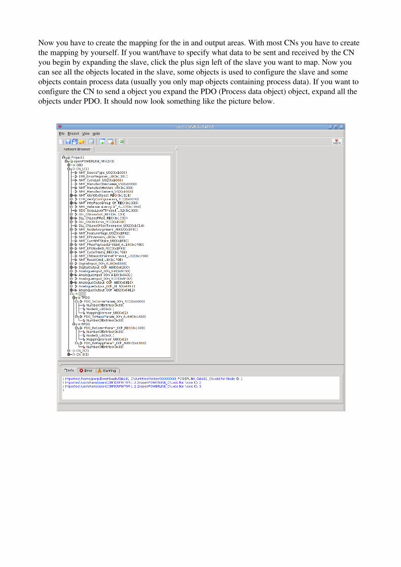
The objects containing the mapping is located at the following addresses: 0x1800, 0x1A00, 0x1600, 0x1400, if they don't exist you have to create them manually, this can be done by right clicking on PDO and click “Add PDO...”, enter the address e.g 0x1800 and press “Ok”. For every object you want the CN to send, you have to create a subindex in the 0x1A00 object. Right click on the object with address 0x1A00 and click “Add SubIndex...”, enter 0x01, press “Ok”. Repeat this for every object you want the CN to send (increment the subindex). Repeat this procedure for the objects you want the CN to receive by adding subindex to object with address 0x1600. When done it should look something like the picture below. CN_1 is configured to send two objects and receive two objects, now you have to specify the objects to send/receive.
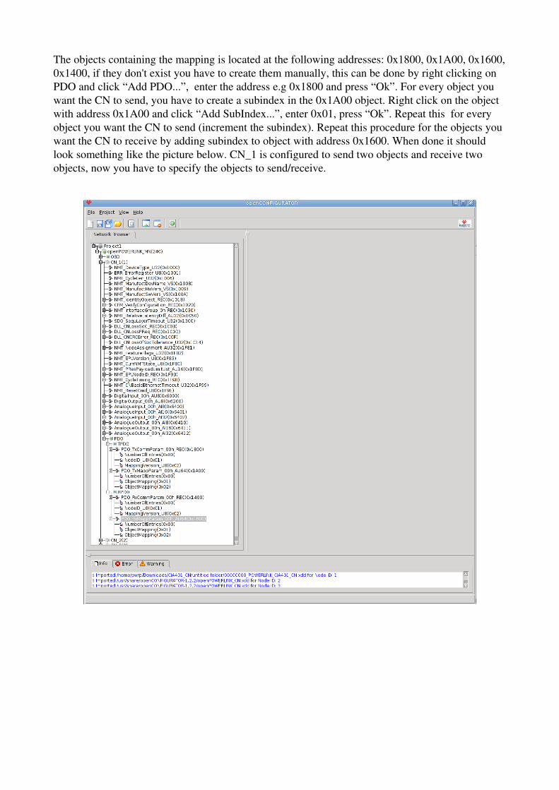
Click the TPDO object and a view of the transmit mapping will visible on the right. Every row represents one object the CN will send, to create more rows you add more subindex to the 0x1A00 object as described above. In each row you input the offset, length, index and subindex of the object you want the CN to send (“Node Id” column should be 0x0, you only change it if you use crosstalk). The first row always have offset 0x0000 (it is the first object in the output area). The picture below show a CN configured to send and receive two objects. The two object the CN will send have a length of 8 bits and is located at address 0x6400 subindex 0x01 and subindex 0x02. The second object must have a offset of 8 bits int the output area since the first objects occupies the first 8 bits. To map the input area of the CN you click the RPDO and add your mapping in the same way as described above.
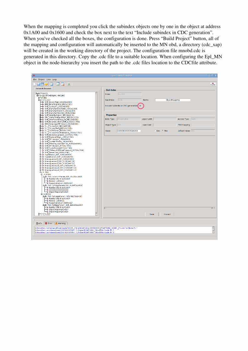
When the mapping is completed you click the subindex objects one by one in the object at address 0x1A00 and 0x1600 and check the box next to the text “Include subindex in CDC generation”. When you've checked all the boxes, the configuration is done. Press “Build Project” button, all of the mapping and configuration will automatically be inserted to the MN obd, a directory (cdc_xap) will be created in the working directory of the project. The configuration file mnobd.cdc is generated in this directory. Copy the .cdc file to a suitable location. When configuring the Epl_MN object in the nodehierarchy you insert the path to the .cdc files location to the CDCfile attribute.
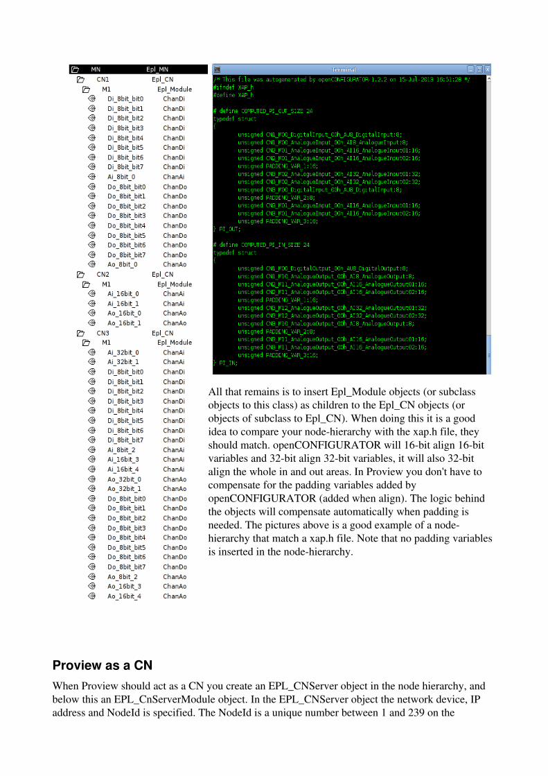
All that remains is to insert Epl_Module objects (or subclass objects to this class) as children to the Epl_CN objects (or objects of subclass to Epl_CN). When doing this it is a good idea to compare your nodehierarchy with the xap.h file, they should match. openCONFIGURATOR will 16bit align 16bit variables and 32bit align 32bit variables, it will also 32bit align the whole in and out areas. In Proview you don't have to compensate for the padding variables added by openCONFIGURATOR (added when align). The logic behind the objects will compensate automatically when padding is needed. The pictures above is a good example of a nodehierarchy that match a xap.h file. Note that no padding variables is inserted in the nodehierarchy.
Proview as a CNWhen Proview should act as a CN you create an EPL_CNServer object in the node hierarchy, and below this an EPL_CnServerModule object. In the EPL_CNServer object the network device, IP address and NodeId is specified. The NodeId is a unique number between 1 and 239 on the
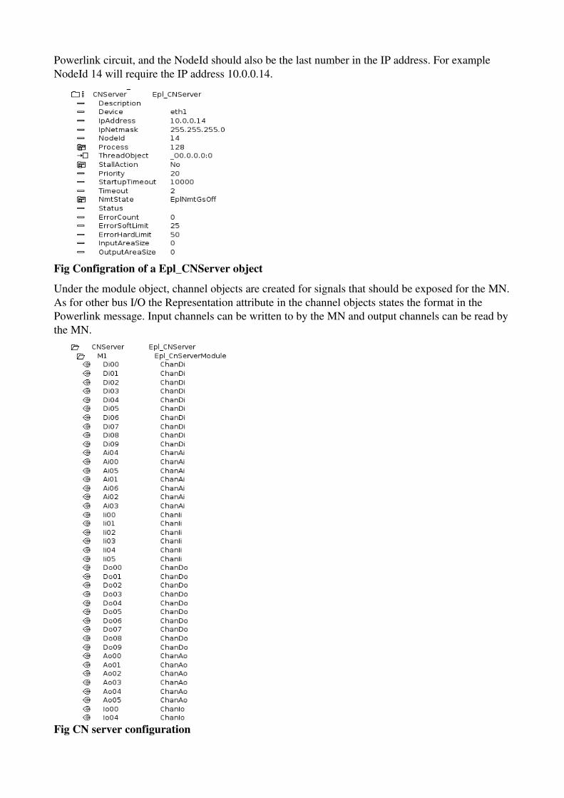
Powerlink circuit, and the NodeId should also be the last number in the IP address. For example NodeId 14 will require the IP address 10.0.0.14.
Fig Configration of a Epl_CNServer object
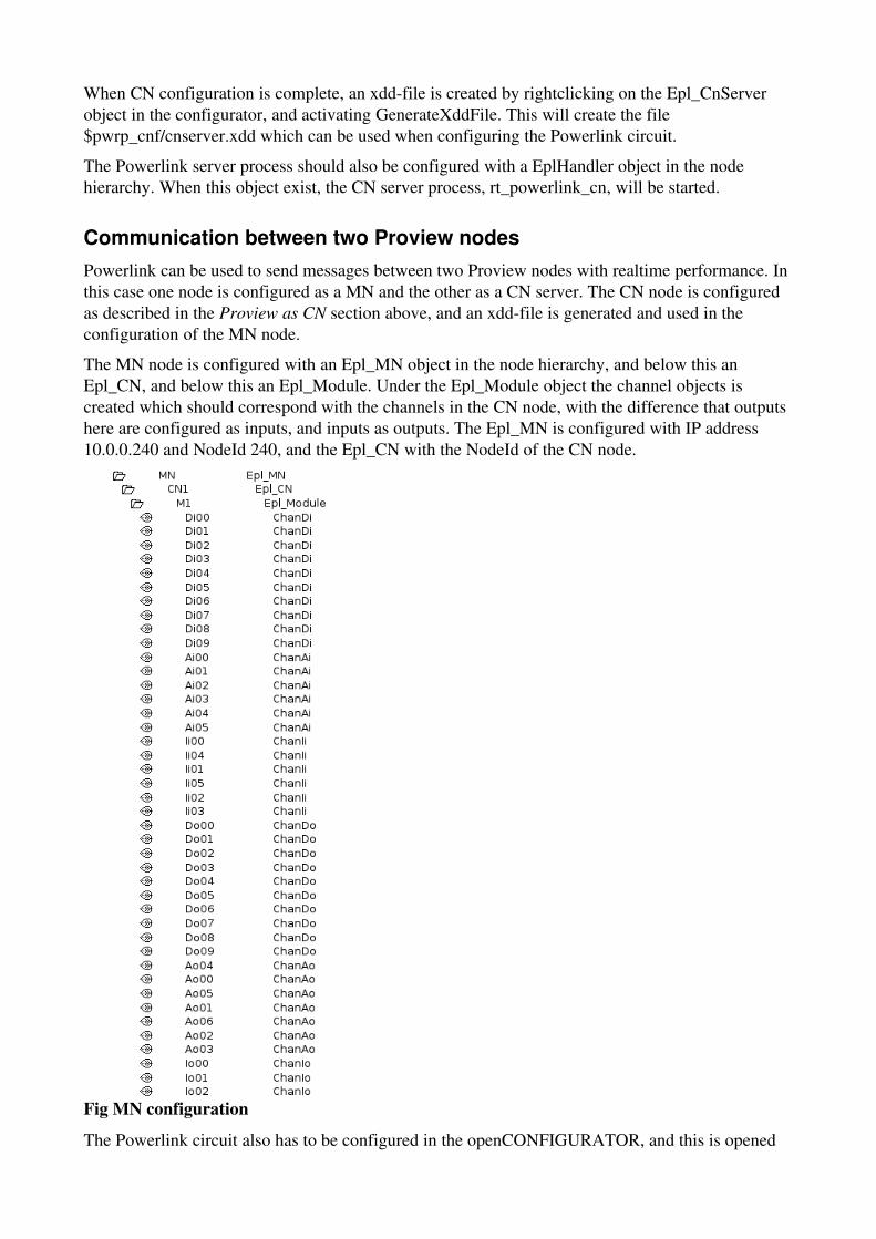
Under the module object, channel objects are created for signals that should be exposed for the MN. As for other bus I/O the Representation attribute in the channel objects states the format in the Powerlink message. Input channels can be written to by the MN and output channels can be read by the MN.
Fig CN server configuration
When CN configuration is complete, an xddfile is created by rightclicking on the Epl_CnServer object in the configurator, and activating GenerateXddFile. This will create the file $pwrp_cnf/cnserver.xdd which can be used when configuring the Powerlink circuit.
The Powerlink server process should also be configured with a EplHandler object in the node hierarchy. When this object exist, the CN server process, rt_powerlink_cn, will be started.
Communication between two Proview nodesPowerlink can be used to send messages between two Proview nodes with realtime performance. In this case one node is configured as a MN and the other as a CN server. The CN node is configured as described in the Proview as CN section above, and an xddfile is generated and used in the configuration of the MN node.
The MN node is configured with an Epl_MN object in the node hierarchy, and below this an Epl_CN, and below this an Epl_Module. Under the Epl_Module object the channel objects is created which should correspond with the channels in the CN node, with the difference that outputs here are configured as inputs, and inputs as outputs. The Epl_MN is configured with IP address 10.0.0.240 and NodeId 240, and the Epl_CN with the NodeId of the CN node.
Fig MN configuration
The Powerlink circuit also has to be configured in the openCONFIGURATOR, and this is opened
by rightclicking on the Epl_MN object and activating ConfigureEpl. Create a new project with Default MN Configuration and AutoGenerate set to Yes.
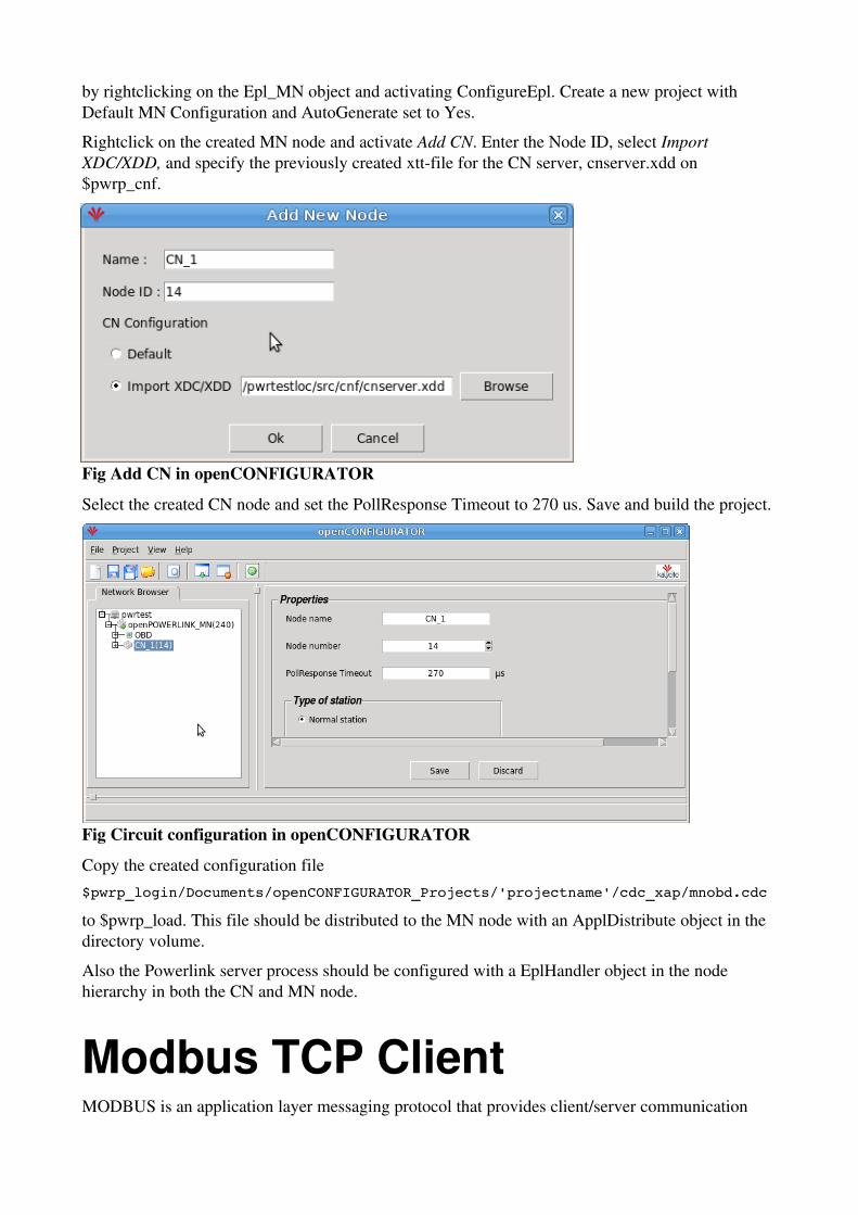
Rightclick on the created MN node and activate Add CN. Enter the Node ID, select Import XDC/XDD, and specify the previously created xttfile for the CN server, cnserver.xdd on $pwrp_cnf.
Fig Add CN in openCONFIGURATOR
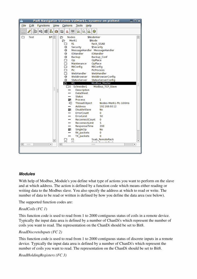
Select the created CN node and set the PollResponse Timeout to 270 us. Save and build the project.
Fig Circuit configuration in openCONFIGURATOR
Copy the created configuration file $pwrp_login/Documents/openCONFIGURATOR_Projects/'projectname'/cdc_xap/mnobd.cdc
to $pwrp_load. This file should be distributed to the MN node with an ApplDistribute object in the directory volume.
Also the Powerlink server process should be configured with a EplHandler object in the node hierarchy in both the CN and MN node.
Modbus TCP ClientMODBUS is an application layer messaging protocol that provides client/server communication

between devices. Proview implements the MODBUS messaging service over TCP/IP.
MODBUS is a request/reply protocol and offers services specified by function codes. For more information on the MODBUS protocol see the documents:
MODBUS Application Protocol Specification V1.1b
MODBUS Messaging on TCP/IP Implementation Guide V1.0b
Each device that is to be communicated with is configured with an object of class Modbus_TCP_Slave, or a subclass to this class. The interface to the device is defined by instances of the class Modbus_Module. Each instance of the Modbus_Module represents a function code for the service that is requested. The corresponding data area is defined with channels.
Configuration of a device
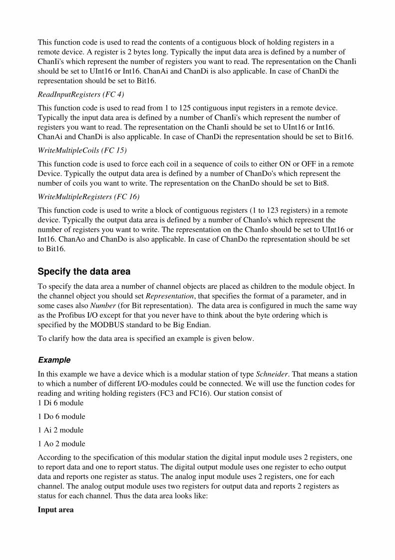
Master
Insert a Modbus_Masterobject in the nodehierarchy. By default all Modbus communication will be handled by one plcthread. Connect the master to a plcthread.
Slaves
As children to the masterobject you configure the devices that you want to communicate with. Each device will be represented by a Modbus_TCP_Slaveobject.
Insert a Modbus_TCP_Slaveobject in the nodehierarchy. Specify the ipaddress of the MODBUS device. By default the device will be handled by a plcthread. Connect the slave to a plcthread. An example is given below.
Modules
With help of Modbus_Module's you define what type of actions you want to perform on the slave and at which address. The action is defined by a function code which means either reading or writing data to the Modbus slave. You also specify the address at which to read or write. The number of data to be read or written is defined by how you define the data area (see below).
The supported function codes are:
ReadCoils (FC 1)
This function code is used to read from 1 to 2000 contiguous status of coils in a remote device. Typically the input data area is defined by a number of ChanDi's which represent the number of coils you want to read. The representation on the ChanDi should be set to Bit8.
ReadDiscreteInputs (FC 2)
This function code is used to read from 1 to 2000 contiguous status of discrete inputs in a remote device. Typically the input data area is defined by a number of ChanDi's which represent the number of coils you want to read. The representation on the ChanDi should be set to Bit8.
ReadHoldingRegisters (FC 3)
This function code is used to read the contents of a contiguous block of holding registers in a remote device. A register is 2 bytes long. Typically the input data area is defined by a number of ChanIi's which represent the number of registers you want to read. The representation on the ChanIi should be set to UInt16 or Int16. ChanAi and ChanDi is also applicable. In case of ChanDi the representation should be set to Bit16.
ReadInputRegisters (FC 4)
This function code is used to read from 1 to 125 contiguous input registers in a remote device. Typically the input data area is defined by a number of ChanIi's which represent the number of registers you want to read. The representation on the ChanIi should be set to UInt16 or Int16. ChanAi and ChanDi is also applicable. In case of ChanDi the representation should be set to Bit16.
WriteMultipleCoils (FC 15)
This function code is used to force each coil in a sequence of coils to either ON or OFF in a remote Device. Typically the output data area is defined by a number of ChanDo's which represent the number of coils you want to write. The representation on the ChanDo should be set to Bit8.
WriteMultipleRegisters (FC 16)
This function code is used to write a block of contiguous registers (1 to 123 registers) in a remote device. Typically the output data area is defined by a number of ChanIo's which represent the number of registers you want to write. The representation on the ChanIo should be set to UInt16 or Int16. ChanAo and ChanDo is also applicable. In case of ChanDo the representation should be set to Bit16.
Specify the data areaTo specify the data area a number of channel objects are placed as children to the module object. In the channel object you should set Representation, that specifies the format of a parameter, and in some cases also Number (for Bit representation). The data area is configured in much the same way as the Profibus I/O except for that you never have to think about the byte ordering which is specified by the MODBUS standard to be Big Endian.
To clarify how the data area is specified an example is given below.
Example
In this example we have a device which is a modular station of type Schneider. That means a station to which a number of different I/Omodules could be connected. We will use the function codes for reading and writing holding registers (FC3 and FC16). Our station consist of1 Di 6 module
1 Do 6 module
1 Ai 2 module
1 Ao 2 module
According to the specification of this modular station the digital input module uses 2 registers, one to report data and one to report status. The digital output module uses one register to echo output data and reports one register as status. The analog input module uses 2 registers, one for each channel. The analog output module uses two registers for output data and reports 2 registers as status for each channel. Thus the data area looks like:
Input area
1 register (2 bytes) digital input data, 6 lowest bits represent the inputs
1 register (2 bytes) digital input status
1 register (2 bytes) echo digital output
1 register, digital output status
1 register, analog input channel 1
1 register, analog input channel 2
1 register, echo analog output channel 1
1 register, echo analog output channel 2
Output area
1 register digital output data, 6 lowest bits represent the outputs
1 register, analog output channel 1
1 register, analog output channel 2
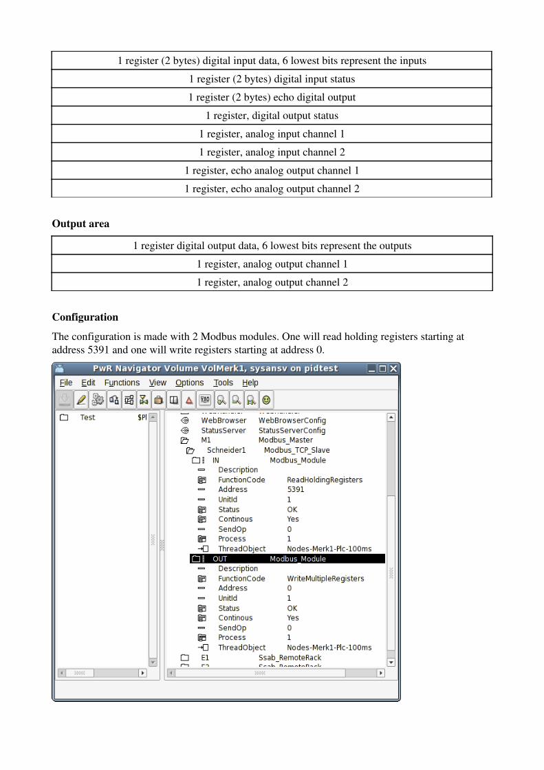
Configuration
The configuration is made with 2 Modbus modules. One will read holding registers starting at address 5391 and one will write registers starting at address 0.
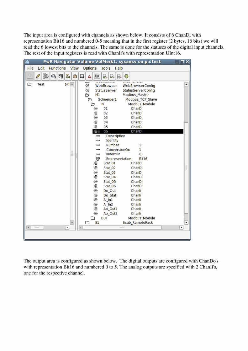
The input area is configured with channels as shown below. It consists of 6 ChanDi with representation Bit16 and numbered 05 meaning that in the first register (2 bytes, 16 bits) we will read the 6 lowest bits to the channels. The same is done for the statuses of the digital input channels. The rest of the input registers is read with ChanIi's with representation UInt16.
The output area is configured as shown below. The digital outputs are configured with ChanDo's with representation Bit16 and numbered 0 to 5. The analog outputs are specified with 2 ChanIi's, one for the respective channel.
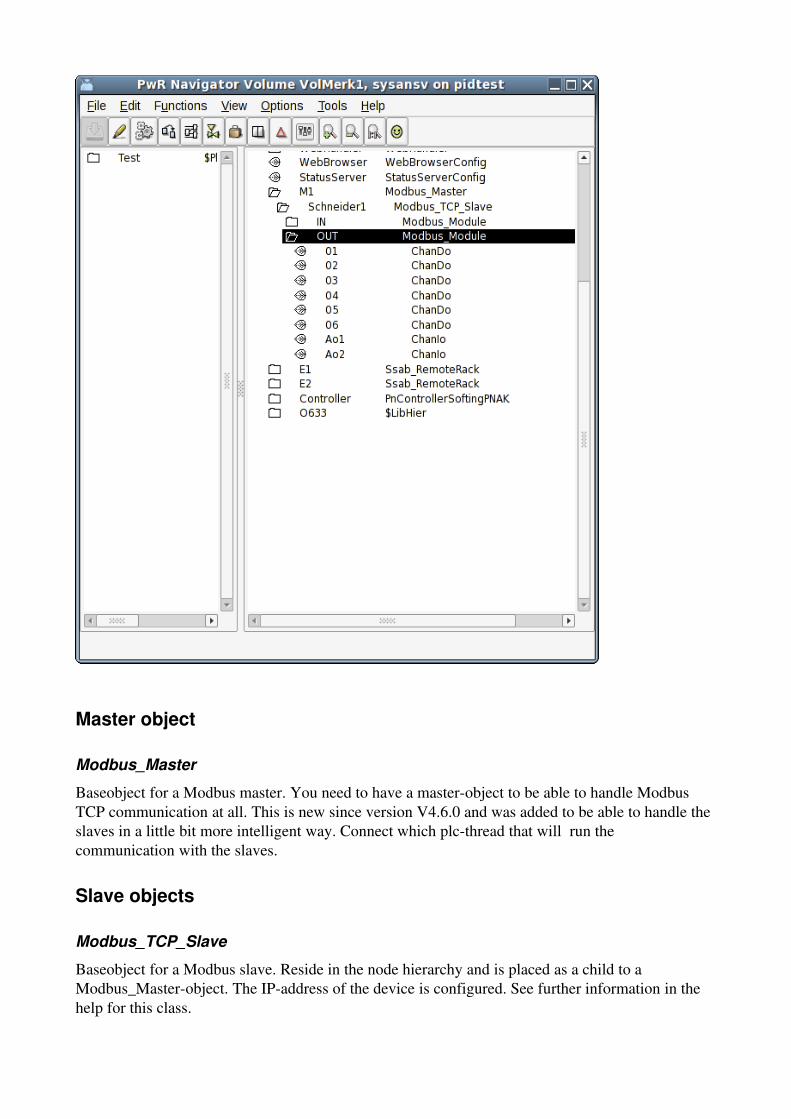
Master object
Modbus_Master
Baseobject for a Modbus master. You need to have a masterobject to be able to handle Modbus TCP communication at all. This is new since version V4.6.0 and was added to be able to handle the slaves in a little bit more intelligent way. Connect which plcthread that will run the communication with the slaves.
Slave objects
Modbus_TCP_Slave
Baseobject for a Modbus slave. Reside in the node hierarchy and is placed as a child to a Modbus_Masterobject. The IPaddress of the device is configured. See further information in the help for this class.

Module objects
Modbus_Module
Baseclass for a Modbus module. Placed as child to a slave object. Wanted function code is chosen. See further information in the help for this class.
Modbus TCP ServerWith the Modbus TCP Server it is possible for external SCADA and storage systems to fetch data from a Proview system via Modbus TCP. It can also be used to exchange data between Proview systems
The server is configured with a Modbus_TCP_Server object in the node hierarchy, and below this with a Modbus_TCP_ServerModule object.
Data areasThe Modbus_TCP_ServerModule object handles two data areas. One area for reading, from which the clients can read at specified offsets, and one for writing, where clients can write data. Each area has a logical start address, which is stated in attributes in the Modbus_TCP_ServerModule object. ReadAddress is the start address for the read area, and WriteAddress is the start address for the write area. To perform a read or write operation, the client has to specify an address, and this address it the sum of the start address and the offset to the channel that is to be written or read. The start address makes it possible not to have overlapping address space for the read and write areas, which might cause confusion on the client side.
The data area are configured with channel objects below the server module. The Representation attributes in the channel objects states the size of each channel and how the data should be interpreted. The normal representation for Di and Do channels are Bit8, where the Number attributes specifies the bit number for the channel, and the normal representation for integer and analog channels are Int16.
Unit idServeral modules can be configured in a node, by creating one Modbus_TCP_ServerModule object for each module. Every module object has to have a unique unit identity, which is stated in the UnitId attribute. This identity is used by the clients to address a specific module.
PortBy default, the Modbus TCP communication uses the port 502.
If you, for example, want to use Modbus TCP for communication between two Proview systems, another port can be stated in the Port attribute of the Modbus_TCP_Server object. The same port also has to be specified in the slave object in the client node.
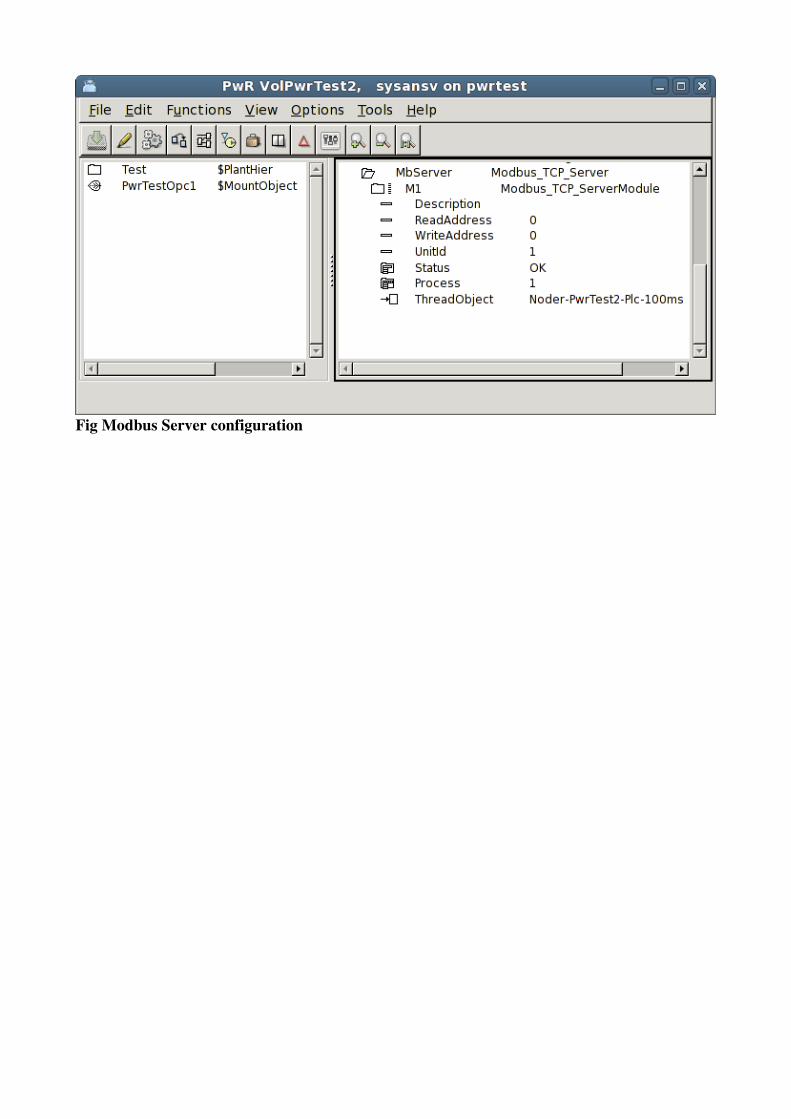
Fig Modbus Server configuration
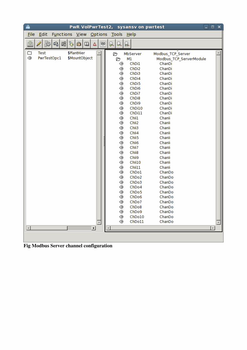
Fig Modbus Server channel configuration
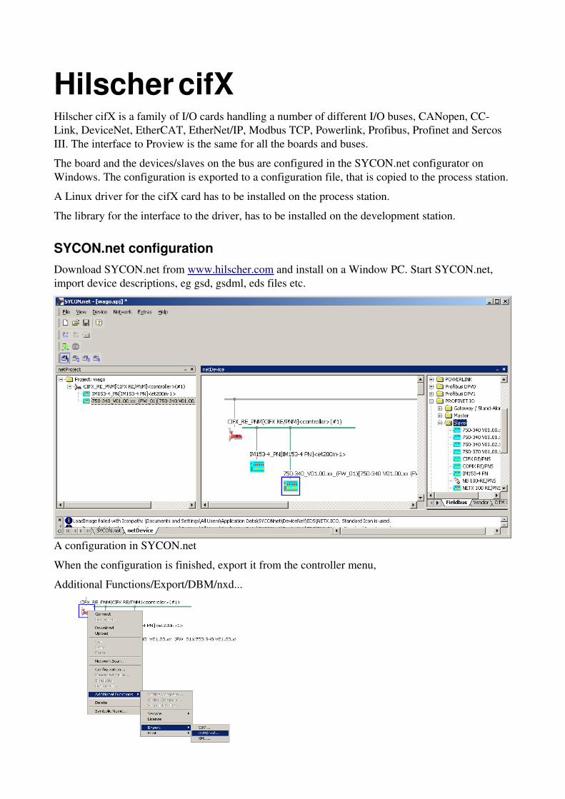
Hilscher cifXHilscher cifX is a family of I/O cards handling a number of different I/O buses, CANopen, CCLink, DeviceNet, EtherCAT, EtherNet/IP, Modbus TCP, Powerlink, Profibus, Profinet and Sercos III. The interface to Proview is the same for all the boards and buses.
The board and the devices/slaves on the bus are configured in the SYCON.net configurator on Windows. The configuration is exported to a configuration file, that is copied to the process station.
A Linux driver for the cifX card has to be installed on the process station.
The library for the interface to the driver, has to be installed on the development station.
SYCON.net configurationDownload SYCON.net from www.hilscher.com and install on a Window PC. Start SYCON.net, import device descriptions, eg gsd, gsdml, eds files etc.
A configuration in SYCON.net
When the configuration is finished, export it from the controller menu,
Additional Functions/Export/DBM/nxd...
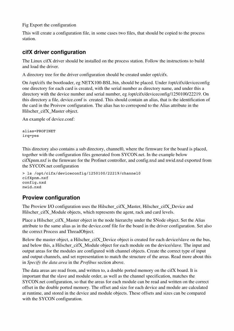
Fig Export the configuration
This will create a configuration file, in some cases two files, that should be copied to the process station.
cifX driver configurationThe Linux cifX driver should be installed on the process station. Follow the instructions to build and load the driver.
A directory tree for the driver configuration should be created under opt/cifx.
On /opt/cifx the bootloader, eg NETX100BSL.bin, should be placed. Under /opt/cifx/deviceconfig one directory for each card is created, with the serial number as directory name, and under this a directory with the device number and serial number, eg /opt/cifx/deviceconfig/1250100/22219. On this directory a file, device.conf is created. This should contain an alias, that is the identification of the card in the Proivew configuration. The alias has to correspond to the Alias attribute in the Hilscher_cifX_Master object.
An example of device.conf:
alias=PROFINET irq=yes
This directory also contains a sub directory, channel0, where the firmware for the board is placed, together with the configuration files generated from SYCON.net. In the example below cifXpnm.nxf is the firmware for the Profinet controller, and config.nxd and nwid.nxd exported from the SYCON.net configuration> ls /opt/cifx/deviceconfig/1250100/22219/channel0cifXpnm.nxfconfig.nxdnwid.nxd
Proview configurationThe Proview I/O configuration uses the Hilscher_cifX_Master, Hilscher_cifX_Device and Hilscher_cifX_Module objects, which represents the agent, rack and card levels.
Place a Hilscher_cifX_Master object in the node hierarchy under the $Node object. Set the Alias attribute to the same alias as in the device.conf file for the board in the driver configuration. Set also the correct Process and ThreadObject.
Below the master object, a Hilscher_cifX_Device object is created for each device/slave on the bus, and below this, a Hilscher_cifX_Module object for each module on the device/slave. The input and output areas for the modules are configured with channel objects. Create the correct type of input and output channels, and set representation to match the structure of the areas. Read more about this in Specify the data area in the Profibus section above.
The data areas are read from, and written to, a double ported memory on the cifX board. It is important that the slave and module order, as well as the channel specification, matches the SYCON.net configuration, so that the areas for each module can be read and written on the correct offset in the double ported memory. The offset and size for each device and module are calculated at runtime, and stored in the device and module objects. These offsets and sizes can be compared with the SYCON configuration.
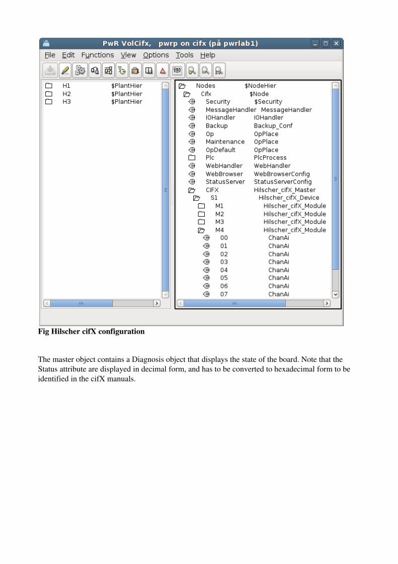
Fig Hilscher cifX configuration
The master object contains a Diagnosis object that displays the state of the board. Note that the Status attribute are displayed in decimal form, and has to be converted to hexadecimal form to be identified in the cifX manuals.
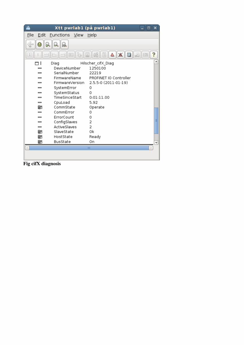
Fig cifX diagnosis
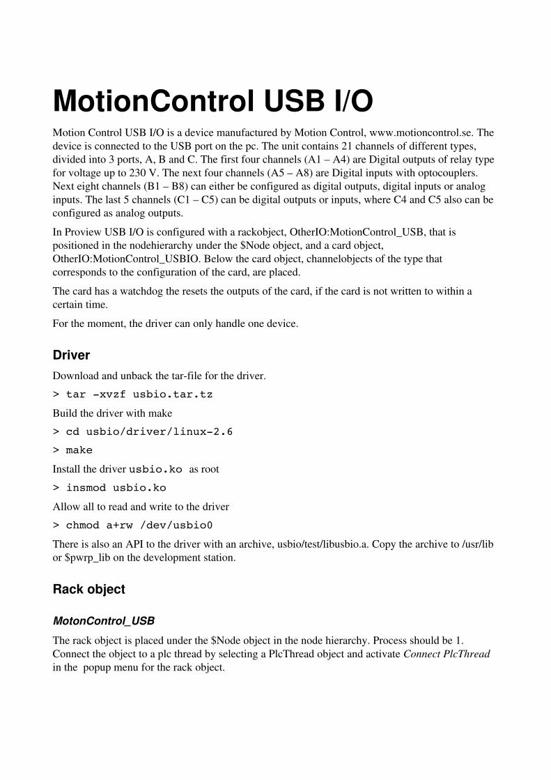
MotionControl USB I/OMotion Control USB I/O is a device manufactured by Motion Control, www.motioncontrol.se. The device is connected to the USB port on the pc. The unit contains 21 channels of different types, divided into 3 ports, A, B and C. The first four channels (A1 – A4) are Digital outputs of relay type for voltage up to 230 V. The next four channels (A5 – A8) are Digital inputs with optocouplers. Next eight channels (B1 – B8) can either be configured as digital outputs, digital inputs or analog inputs. The last 5 channels (C1 – C5) can be digital outputs or inputs, where C4 and C5 also can be configured as analog outputs.
In Proview USB I/O is configured with a rackobject, OtherIO:MotionControl_USB, that is positioned in the nodehierarchy under the $Node object, and a card object, OtherIO:MotionControl_USBIO. Below the card object, channelobjects of the type that corresponds to the configuration of the card, are placed.
The card has a watchdog the resets the outputs of the card, if the card is not written to within a certain time.
For the moment, the driver can only handle one device.
DriverDownload and unback the tarfile for the driver.
> tar xvzf usbio.tar.tz
Build the driver with make
> cd usbio/driver/linux2.6
> make
Install the driver usbio.ko as root
> insmod usbio.ko
Allow all to read and write to the driver
> chmod a+rw /dev/usbio0
There is also an API to the driver with an archive, usbio/test/libusbio.a. Copy the archive to /usr/lib or $pwrp_lib on the development station.
Rack object
MotonControl_USB
The rack object is placed under the $Node object in the node hierarchy. Process should be 1. Connect the object to a plc thread by selecting a PlcThread object and activate Connect PlcThread in the popup menu for the rack object.
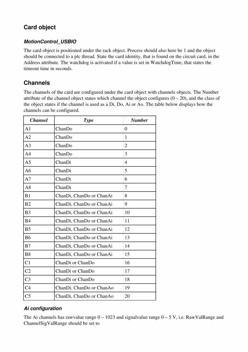
Card object
MotionControl_USBIO
The card object is positioned under the rack object. Process should also here be 1 and the object should be connected to a plc thread. State the card identity, that is found on the circuit card, in the Address attribute. The watchdog is activated if a value is set in WatchdogTime, that states the timeout time in seconds.
ChannelsThe channels of the card are configured under the card object with channels objects. The Number attribute of the channel object states which channel the object configures (0 – 20), and the class of the object states if the channel is used as a Di, Do, Ai or Ao. The table below displays how the channels can be configured.
Channel Type Number
A1 ChanDo 0
A2 ChanDo 1
A3 ChanDo 2
A4 ChanDo 3
A5 ChanDi 4
A6 ChanDi 5
A7 ChanDi 6
A8 ChanDi 7
B1 ChanDi, ChanDo or ChanAi 8
B2 ChanDi, ChanDo or ChanAi 9
B3 ChanDi, ChanDo or ChanAi 10
B4 ChanDi, ChanDo or ChanAi 11
B5 ChanDi, ChanDo or ChanAi 12
B6 ChanDi, ChanDo or ChanAi 13
B7 ChanDi, ChanDo or ChanAi 14
B8 ChanDi, ChanDo or ChanAi 15
C1 ChanDi or ChanDo 16
C2 ChanDi or ChanDo 17
C3 ChanDi or ChanDo 18
C4 ChanDi, ChanDo or ChanAo 19
C5 ChanDi, ChanDo or ChanAo 20
Ai configuration
The Ai channels has rawvalue range 0 – 1023 and signalvalue range 0 – 5 V, i.e. RawValRange and ChannelSigValRange should be set to
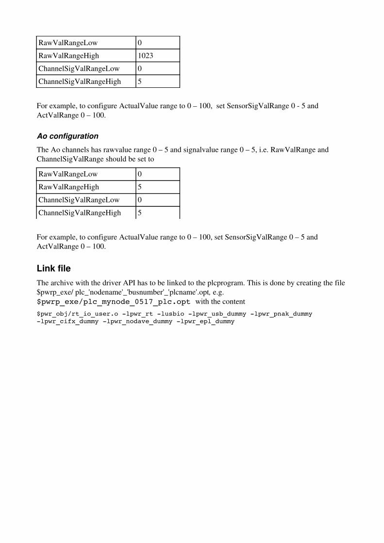
RawValRangeLow 0
RawValRangeHigh 1023
ChannelSigValRangeLow 0
ChannelSigValRangeHigh 5
For example, to configure ActualValue range to 0 – 100, set SensorSigValRange 0 5 and ActValRange 0 – 100.
Ao configuration
The Ao channels has rawvalue range 0 – 5 and signalvalue range 0 – 5, i.e. RawValRange and ChannelSigValRange should be set to
RawValRangeLow 0
RawValRangeHigh 5
ChannelSigValRangeLow 0
ChannelSigValRangeHigh 5
For example, to configure ActualValue range to 0 – 100, set SensorSigValRange 0 – 5 and ActValRange 0 – 100.
Link fileThe archive with the driver API has to be linked to the plcprogram. This is done by creating the file $pwrp_exe/ plc_'nodename'_'busnumber'_'plcname'.opt, e.g. $pwrp_exe/plc_mynode_0517_plc.opt with the content
$pwr_obj/rt_io_user.o lpwr_rt lusbio lpwr_usb_dummy lpwr_pnak_dummy lpwr_cifx_dummy lpwr_nodave_dummy lpwr_epl_dummy
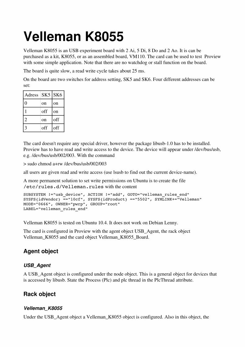
Velleman K8055Velleman K8055 is an USB experiment board with 2 Ai, 5 Di, 8 Do and 2 Ao. It is can be purchased as a kit, K8055, or as an assembled board, VM110. The card can be used to test Proview with some simple application. Note that there are no watchdog or stall function on the board.
The board is quite slow, a read write cycle takes about 25 ms.
On the board are two switches for address setting, SK5 and SK6. Four different addresses can be set:
Adress SK5 SK6
0 on on
1 off on
2 on off
3 off off
The card doesn't require any special driver, however the package libusb1.0 has to be installed. Proview has to have read and write access to the device. The device will appear under /dev/bus/usb, e.g. /dev/bus/usb/002/003. With the command
> sudo chmod a+rw /dev/bus/usb/002/003
all users are given read and write access (use lsusb to find out the current devicename).
A more permanent solution to set write permissions on Ubuntu is to create the file /etc/rules.d/Velleman.rules with the content
SUBSYSTEM !="usb_device", ACTION !="add", GOTO="velleman_rules_end" SYSFS{idVendor} =="10cf", SYSFS{idProduct} =="5502", SYMLINK+="Velleman" MODE="0666", OWNER="pwrp", GROUP="root" LABEL="velleman_rules_end"
Velleman K8055 is tested on Ubuntu 10.4. It does not work on Debian Lenny.
The card is configured in Proview with the agent object USB_Agent, the rack object Velleman_K8055 and the card object Velleman_K8055_Board.
Agent object
USB_Agent
A USB_Agent object is configured under the node object. This is a general object for devices that is accessed by libusb. State the Process (Plc) and plc thread in the PlcThread attribute.
Rack object
Velleman_K8055
Under the USB_Agent object a Velleman_K8055 object is configured. Also in this object, the
Process and PlcThread has to be stated.
Card object
Velleman_K8055_Board
Beneath the rack object, a card object of type Velleman_K8055_Board is configured. You can have up to 4 cards in one system. State Process and PlcThread, and state the card address in the Address attribute.
ChannelsAll channelobjects reside internally in the card object, Velleman_K8055_Board. There are one array with two ChanAi objects, one array with 5 ChanDi objects, one array with 2 ChanAo objects, and one array with ChanDo objects. Connect the channel object to suitable signal objects.
Ai configuration
The Ai channels has rawvalue range 0 – 255 and signalvalue range 0 – 5 V, i.e. RawValRange and ChannelSigValRange should be set to
RawValRangeLow 0
RawValRangeHigh 255
ChannelSigValRangeLow 0
ChannelSigValRangeHigh 5
For example, to configure ActualValue range to 0 – 100, set SensorSigValRange 0 5 and ActValRange 0 – 100.
Ao configuration
The Ao channels has rawvalue range 0 – 255 and signalvalue range 0 – 5, i.e. RawValRange and ChannelSigValRange should be set to
RawValRangeLow 0
RawValRangeHigh 255
ChannelSigValRangeLow 0
ChannelSigValRangeHigh 5
For example, to configure ActualValue range to 0 – 100, set SensorSigValRange 0 – 5 and ActValRange 0 – 100.
Link fileThe archive libusb1.0 has to be linked to the plcprogram. This is done by creating the file $pwrp_exe/ plc_'nodename'_'busnumber'_'plcname'.opt, e.g. $pwrp_exe/plc_mynode_0517_plc.opt with the content$pwr_obj/rt_io_user.o lpwr_rt lusb1.0 lpwr_usbio_dummy lpwr_pnak_dummy

lpwr_cifx_dummy lpwr_nodave_dummy lpwr_epl_dummy
Fig Velleman K8055 configuration
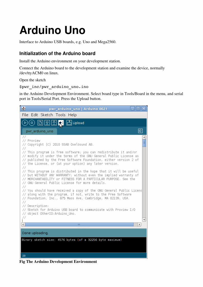
Arduino UnoInterface to Arduino USB boards, e.g. Uno and Mega2560.
Initialization of the Arduino boardInstall the Arduino environment on your development station.
Connect the Arduino board to the development station and examine the device, normally /dev/ttyACM0 on linux.
Open the sketch
$pwr_inc/pwr_arduino_uno.ino
in the Arduino Development Environment. Select board type in Tools/Board in the menu, and serial port in Tools/Serial Port. Press the Upload button.
Fig The Arduino Development Environment
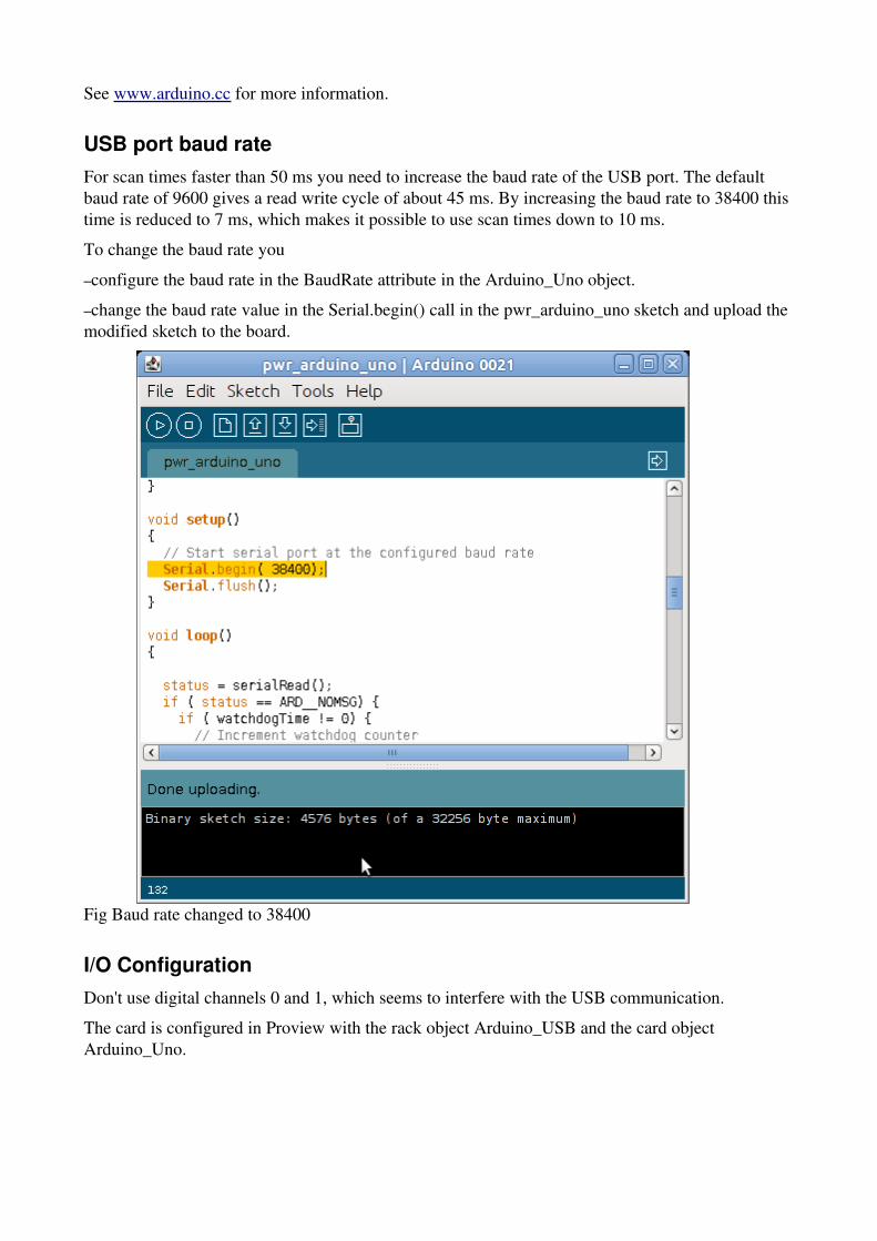
See www.arduino.cc for more information.
USB port baud rate For scan times faster than 50 ms you need to increase the baud rate of the USB port. The default baud rate of 9600 gives a read write cycle of about 45 ms. By increasing the baud rate to 38400 this time is reduced to 7 ms, which makes it possible to use scan times down to 10 ms.
To change the baud rate you
–configure the baud rate in the BaudRate attribute in the Arduino_Uno object.
–change the baud rate value in the Serial.begin() call in the pwr_arduino_uno sketch and upload the modified sketch to the board.
Fig Baud rate changed to 38400
I/O ConfigurationDon't use digital channels 0 and 1, which seems to interfere with the USB communication.
The card is configured in Proview with the rack object Arduino_USB and the card object Arduino_Uno.
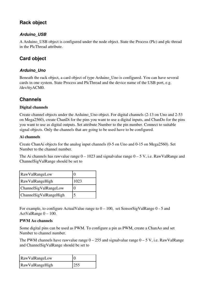
Rack object
Arduino_USB
A Arduino_USB object is configured under the node object. State the Process (Plc) and plc thread in the PlcThread attribute.
Card object
Arduino_Uno
Beneath the rack object, a card object of type Arduino_Uno is configured. You can have several cards in one system. State Process and PlcThread and the device name of the USB port, e.g. /dev/ttyACM0.
ChannelsDigital channels
Create channel objects under the Arduino_Uno object. For digital channels (213 on Uno and 253 on Mega2560), create ChanDi for the pins you want to use a digital inputs, and ChanDo for the pins you want to use as digital outputs. Set attribute Number to the pin number. Connect to suitable signal objects. Only the channels that are going to be used have to be configured.
Ai channels
Create ChanAi objects for the analog input channels (05 on Uno and 015 on Mega2560). Set Number to the channel number.
The Ai channels has rawvalue range 0 – 1023 and signalvalue range 0 – 5 V, i.e. RawValRange and ChannelSigValRange should be set to
RawValRangeLow 0
RawValRangeHigh 1023
ChannelSigValRangeLow 0
ChannelSigValRangeHigh 5
For example, to configure ActualValue range to 0 – 100, set SensorSigValRange 0 5 and ActValRange 0 – 100.
PWM Ao channels
Some digital pins can be used as PWM. To configure a pin as PWM, create a ChanAo and set Number to channel number.
The PWM channels have rawvalue range 0 – 255 and signalvalue range 0 – 5 V, i.e. RawValRange and ChannelSigValRange should be set to
RawValRangeLow 0
RawValRangeHigh 255
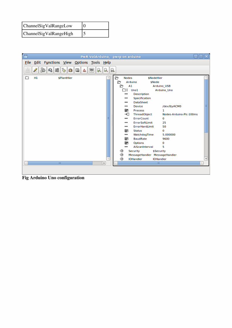
ChannelSigValRangeLow 0
ChannelSigValRangeHigh 5
Fig Arduino Uno configuration

Fig Arduino Uno channel configuration
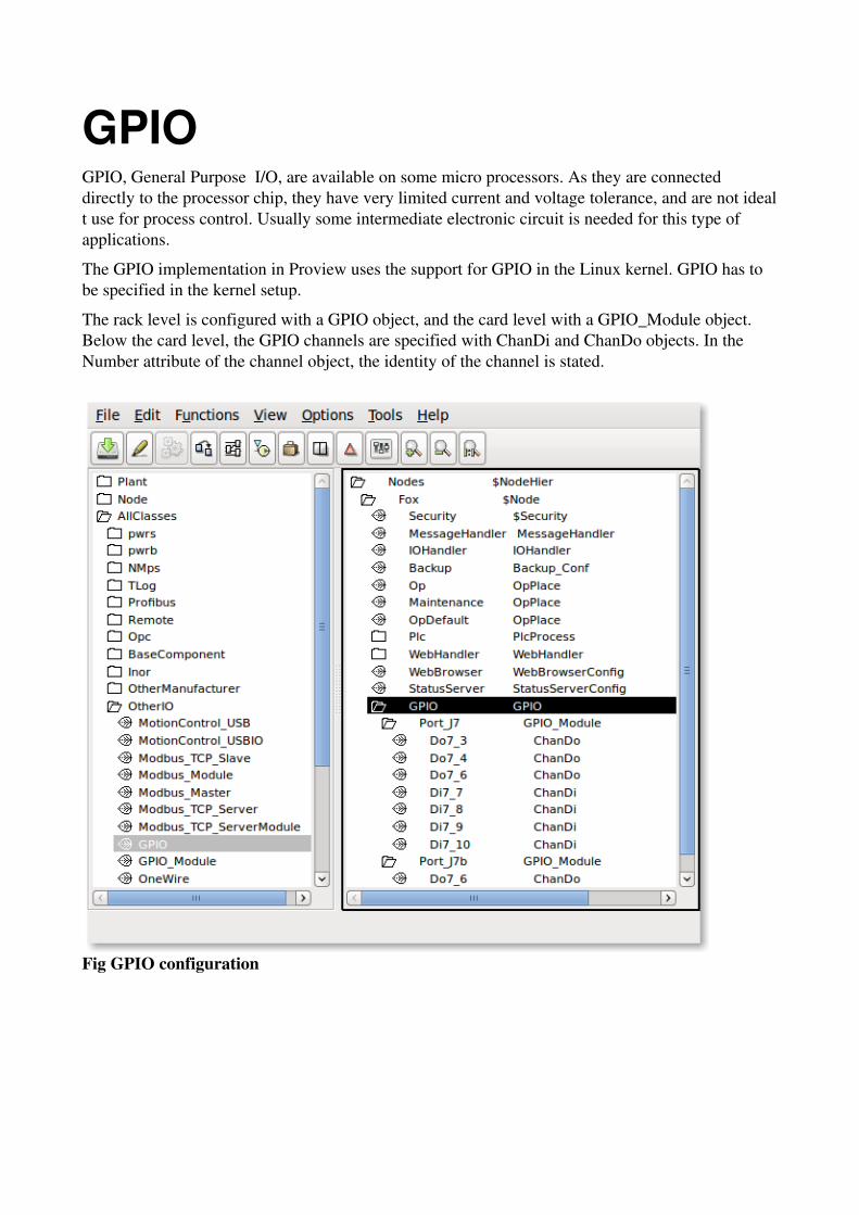
GPIOGPIO, General Purpose I/O, are available on some micro processors. As they are connected directly to the processor chip, they have very limited current and voltage tolerance, and are not ideal t use for process control. Usually some intermediate electronic circuit is needed for this type of applications.
The GPIO implementation in Proview uses the support for GPIO in the Linux kernel. GPIO has to be specified in the kernel setup.
The rack level is configured with a GPIO object, and the card level with a GPIO_Module object. Below the card level, the GPIO channels are specified with ChanDi and ChanDo objects. In the Number attribute of the channel object, the identity of the channel is stated.
Fig GPIO configuration
OneWire1Wire is a serial bus system with low speed data transfer.
The rack level is configured with a OneWire object, and below this, the card objects for components attached to the 1Wire circuit.
The 1Wire implementation in Proview uses the support for 1Wire in the Linux kernel. 1Wire has to be specified in the kernel setup.
1Wire devices has an identity that has to be stated in the Address attribute of the card object. The identity should be stated in decimal form. To retrieve the identity, attach the sensor to the bus, and list the directory /sys/bus/w1/w1 bus master.
> ls /sys/bus/w1/w1\ bus\ master
280000028fa89c
The first number is the family (28) and the last number is the identity (28fa89c) in hexadecimal form. This should be converted to decimal and inserted into the Address attribute.
OneWire_AiDeviceA generic object for an analog input device connected to the 1wire bus.
The path of the file containing the sensor value is stated in the DataFile attribute. A %s in the filename will be replaced by the family and serial number, eg “280000028fa89c”.
A search string is stated in ValueSearchString to indicate where in the file the sensor value is located. When reading the value, the search string is searched for, and and the value is expected to be found after the search string. If the search string is empty, the value will be read from the beginning of the file.
The object contains an Ai channel, that should be connected to an Ai signal. The range attributes should be set in the channel object. If the sensor value in the file is given as a integer value, set Representation to Int32, if it is given as a float, set Representation to Float32.
Maxim_DS18B20Card object for a DS18B20 temperature sensor. The identity of the sensor should be stated in the Address attribute. The object contains a ChanAi object that should be connected to an Ai object. The rawvalue range is 55000 – 125000 which corresponds to an actvalrange of 55 – 125 C. A read operation with 12 bit resolution takes about 750 ms.
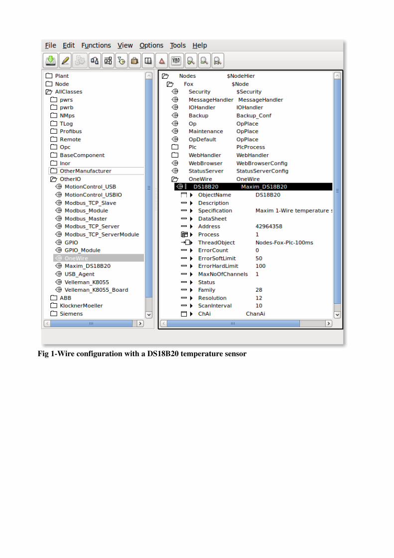
Fig 1Wire configuration with a DS18B20 temperature sensor
Adaption of I/O systems
This section will describe how to add new I/O systems to Proview.
Adding a new I/O system requires knowledge of how to create classes in Proview, and baseknowledge of c programming.
An I/O system can be added for a single project, for a number of projects, or for the Proview base system. In the latter case you have to install and build from the Proview source code.
OverviewThe I/O handling in Proview consist of a framework that identifies the I/O objects on a process node, and calls the methods of the I/O objects to fetch or transmit data.
LevelsThe I/O objects in a process node are configured in four levels: agent, rack, cards and channels. The channelobjects can be configured as individual objects or as internal objects in a card object.
To the agent, rack and card objects methods can be registered. The methods can be of type Init, Close, Read, Write or Swap, and is called by the I/O framework in a specific order. The functionality of an I/O object consists of the attributes of the object, and the registered methods of the object. Everything the framework does is to identify the objects, select the objects that are valid for the current process, and call the methods for these objects in a specific order.
Look at a centralized I/O system with digital inputcards and digital outputcards mounted on the local bus of the process node. In this case the agent level is superfluous and represented by the $Node object. Below the $Node object is placed a rack object with an open and a close method. The open method attaches to the driver of the I/O system. Below the rack object, cardobjects for the Di and Do cards are configured. The Di card has an Open and a Close method that initiates and closes down the card, and a Read method the fetches the values of the inputs of the card. The Do card also has Open and Close methods, and a Write method that transfers suitable values to the outputs of the card.
If we study another I/O system, Profibus, the levels are not as easy to identify as in the previous example. Profibus is a distributes system, with a master card mounted on the local PCIbus, that communicates via a serial connection to slaves positioned in the plant. Each slave can contain modules of different type, e.g. one module with 4 Di channels, and one with 2 Ao channels. In this case the master card represents the agent level, the slaves the rack level and the modules the card level.
The Agent, rack and card levels are very flexible, and mainly defined by the attributes and the methods of the classes of the I/O system. This does not apply to the channel level that consists of the object ChanDi, ChanDo, ChanAi, ChanAo, ChanIi, ChanIo and ChanCo. The task for the channel object is to represent an input or output value on an I/O unit, and transfer this value to the signal object that is connected to the channel object. The signal object reside in the plant hierarchy and represents for example a sensor or an order to an actuator in the plant. As there is a physical
connection between the sensor in the plant and the channel on the I/O card, also the signal objects are connected to the channel object. Plcprograms, HMI and applications refer to the signal object that represents the component in the plant, not the channel object, representing a channel on an I/O unit.
Area objectsValues that are fetched from input units and values that are put out to output units are stored in special area objects. The area objects are created dynamically in runtime and reside in the system volume under the hierarchy pwrNodeactiveio. There are one area object for each signal type. Normally you refer to the value of a signal through the ActualValue attribute of the signal. This attribute actually contains a pointer that points to the area object, and the attribute ValueIndex states in which index in the area object the signal value can be found. The reason to this construction with area objects is that during the execution of a logical net, you don't want any changes of signal values. Each plctread therefor takes a copy of the area objects before the start of the execution, and reads signal values from the copy, calculated output signal values though, are written in the area object.
I/O objectsThe configuration of the I/O is done in the node hierarchy below the $Node object. To each type of component in the I/O hierarchy you create a class that contains attributes and methods. The methods are of type Open, Close, Read, Write and Swap, and is called by the I/O framework. The methods connects to the bus and read data that are transferred to the area objects, or fetches data from the area objects that are put out on the bus.
ProcessesThere are two system processes in Proview that calls the I/O framework,the plc process and rt_io_comm. In the plc process each thread makes an initialization of the I/O framework, which makes it possible to read and write I/O units synchronized with the execution of the plc code for the threads.
FrameworkThe main task for the I/O framework is to identify I/O objects and call the methods that are registered for the objects.
A first initialization is made at start of the runtime environment, when the area objects are created, and each signal is allocated a place in the area object. The connections between signals and channels are also checked. When signals and channels are connected in the development environment, the identity for the channel is stored in the signals SigChanCon attribute. Now the identity of the signal object is put into the channels SigChanCon attribute, thus making it easy to find the signal from the channel.
The next initialization is made by every process that wants to connect to the I/O handling. The plc process and rt_io_comm does this initialization, but also applications that need to read or write directly to I/O units can connect. At the initialization a data structure i allocated with all agents, racks, cards and channels that is to be handled by the current process, and the init methods for them are called. The process then makes a cyclic call of a read and write function, that calls the read and write methods for the I/O objects in the data structure.
MethodsThe task of the methods are to initiate the I/O system, perform reading and writing to the I/O units, and finally disconnect the I/O system. How these tasks are divided, depend on the construction of the I/O system. In a centralized I/O on the local bus, methods for the different card objects can attach the bus and read and write data themselves to their unit, and the methods for the agent and rack object doesn't have much to do. In a distributed I/O the information for the units are often gathered in a package, and it is the methods of the agent or rack object that receives the package and distribute its content on different card objects. The card object methods identifies data for its channels, performs any conversion and writes or reads data in the area object.
FrameworkA process can initiate the I/O framework by calling io_ini(). As argument you send a bitmask that indicates which process you are, and the threads of the plc process also states the current thread. io_init() preforms the following
● creates a context.
● allocates a hierarchic data structure of I/O objects with the levels agent, rack, card and channel. For agents a struct of type io_sAgent is allocated, for racks a struct of type io_sRack, for cards a struct of type io_sCard, and finally for channels a struct of type io_sChannel.
● searches for all I/O objects and checks their Process attributes. If the Process attribute matches the process sent as an argument to io_init(), the object is inserted into the data structure. If the object has a descendant that matches the process it is also inserted into the data structure. For the plc process, also the thread argument of io_init() is checked against the ThreadObject attribute in the I/O object. The result is a linked tree structure with the agents, racks, card and channel objects that is to be handled by the current process.
● for every I/O objects that is inserted, the methods are identified, and pointers to the method functions are fetched. Also pointers to the object and the objects name, is inserted in the data structure.
● the init methods for the I/O objects in the data structure is called. The methods of the first agent is called first, and then the first rack of the agent, the first card of the rack etc.
When the initialization is done, the process can call io_read() to read from the I/O units that are present i the data structure, and io_write() to put out values. A thread in the plc process calls io_read() every scan to fetch new values from the process. Then the plccode is executed and io_write() is called to put out new values. The read methods are called in the same order as the init methods, and the write methods in reverse order.
When the process terminates, io_close() is called, which calls the close methods of the objects in the data structure. The close methods are called in reverse order compared to the init methods.
The swap method has an event argument that indicates which type of event has occurred, and in some cases also from where it is called. The swap method is called when emergency break is set and the IO should stop, and when a soft restart is performed.
When a soft restart is performed, a restart of the I/O handling is also performed. First the close methods are called, and then, during the time the restart lasts, the swap methods are called, and then the init methods. The call to the swap methods are done by rt_io_comm.
io_init, function to initiate the frameworkpwr_tStatus io_init( io_mProcess process, pwr_tObjid thread, io_tCtx *ctx, int relativ_vector, float scan_time);
io_sCtx, the context of the frameworkstruct io_sCtx { io_sAgent *agentlist; /* List of agent structures */ io_mProcess Process; /* Callers process number */ pwr_tObjid Thread; /* Callers thread objid */ int RelativVector; /* Used by plc */ pwr_sNode *Node; /* Pointer to node object */ pwr_sClass_IOHandler *IOHandler; /* Pointer to IO Handler object */ float ScanTime; /* Scantime supplied by caller */ io_tSupCtx SupCtx; /* Context for supervise object lists */};
Data structure for an agenttypedef struct s_Agent { pwr_tClassId Class; /* Class of agent object */ pwr_tObjid Objid; /* Objid of agent object */ pwr_tOName Name; /* Full name of agent object */ io_mAction Action; /* Type of method defined (Read/Write)*/ io_mProcess Process; /* Process number */ pwr_tStatus (* Init) (); /* Init method */ pwr_tStatus (* Close) (); /* Close method */ pwr_tStatus (* Read) (); /* Read method */ pwr_tStatus (* Write) (); /* Write method */ pwr_tStatus (* Swap) (); /* Write method */ void *op; /* Pointer to agent object */ pwr_tDlid Dlid; /* Dlid for agent object pointer */ int scan_interval; /* Interval between scans */ int scan_interval_cnt;/* Counter to detect next time to scan */ io_sRack *racklist; /* List of rack structures */ void *Local; /* Pointer to method defined data structure*/ struct s_Agent *next; /* Next agent */} io_sAgent;
Datastructure for a racktypedef struct s_Rack { pwr_tClassId Class; /* Class of rack object */ pwr_tObjid Objid; /* Objid of rack object */ pwr_tOName Name; /* Full name of rack object */ io_mAction Action; /* Type of method defined (Read/Write)*/ io_mProcess Process; /* Process number */ pwr_tStatus (* Init) (); /* Init method */ pwr_tStatus (* Close) (); /* Close method */ pwr_tStatus (* Read) (); /* Read method */ pwr_tStatus (* Write) (); /* Write method */ pwr_tStatus (* Swap) (); /* Swap method */ void *op; /* Pointer to rack object */ pwr_tDlid Dlid; /* Dlid for rack object pointer */
pwr_tUInt32 size; /* Size of rack data area in byte */ pwr_tUInt32 offset; /* Offset to rack data area in agent */ int scan_interval; /* Interval between scans */ int scan_interval_cnt;/* Counter to detect next time to scan */ int AgentControlled;/* TRUE if controlled by agent */ io_sCard *cardlist; /* List of card structures */ void *Local; /* Pointer to method defined data structure*/ struct s_Rack *next; /* Next rack */} io_sRack;
Data structure for a cardtypedef struct s_Card { pwr_tClassId Class; /* Class of card object */ pwr_tObjid Objid; /* Objid of card object */ pwr_tOName Name; /* Full name of card object */ io_mAction Action; /* Type of method defined (Read/Write)*/ io_mProcess Process; /* Process number */ pwr_tStatus (* Init) (); /* Init method */ pwr_tStatus (* Close) (); /* Close method */ pwr_tStatus (* Read) (); /* Read method */ pwr_tStatus (* Write) (); /* Write method */ pwr_tStatus (* Swap) (); /* Write method */ pwr_tAddress *op; /* Pointer to card object */ pwr_tDlid Dlid; /* Dlid for card object pointer */ pwr_tUInt32 size; /* Size of card data area in byte */ pwr_tUInt32 offset; /* Offset to card data area in rack */ int scan_interval; /* Interval between scans */ int scan_interval_cnt;/* Counter to detect next time to scan */ int AgentControlled;/* TRUE if controlled by agent */ int ChanListSize; /* Size of chanlist */ io_sChannel *chanlist; /* Array of channel structures */ void *Local; /* Pointer to method defined data structure*/ struct s_Card *next; /* Next card */} io_sCard;
Data structure for a channeltypedef struct { void *cop; /* Pointer to channel object */ pwr_tDlid ChanDlid; /* Dlid for pointer to channel */ pwr_sAttrRef ChanAref; /* AttrRef for channel */ void *sop; /* Pointer to signal object */ pwr_tDlid SigDlid; /* Dlid for pointer to signal */ pwr_sAttrRef SigAref; /* AttrRef for signal */ void *vbp; /* Pointer to valuebase for signal */ void *abs_vbp; /* Pointer to absvaluebase (Co only) */ pwr_tClassId ChanClass; /* Class of channel object */ pwr_tClassId SigClass; /* Class of signal object */ pwr_tUInt32 size; /* Size of channel in byte */ pwr_tUInt32 offset; /* Offset to channel in card */ pwr_tUInt32 mask; /* Mask for bit oriented channels */} io_sChannel;
Create I/O objectsFor a process node the I/O system is configured in the node hierarchy with objects of type agent, rack and card. The classes for these objects are created in the class editor. The classes are defined with a $ClassDef object, a $ObjBodyDef object (RtBody), and below this one $Attribute object for each attribute of the class. The attributes are determined by the functionality of the methods of the
class, but there are som common attributes (Process, ThreadObject and Description). In the $ClassDef objects, the Flag word should be stated if it is an agent, rack or card object, and the methods are defined with specific Method objects.
It is quite common that several classes in an I/O system share attributes and maybe even methods. An input card that is available with different number of inputs, can often use the same methods. What differs is the number of channel objects. The other attributes can be stored in a baseclass, that also contains the methodsobjects. The subclasses inherits both the attributes and the methods. The y are extended with channel objects, that can be put as individual attributes, or, if they are of the same type, as a vector of channel objects. If the channels are put as a vector or as individual attributes, depend on the how the reference in the plc documents should look. With an array you get an index starting from zero, with individual objects you can control the naming of the attributes yourself.
In the example below a baseclass is viewed in Fig Example of a baseclass and a subclass in Fig Example of a cardclass with a superclass and 32 channel objects. The baseclass Ssab_BaseDiCard contains all the attributes used by the I/O methods and the I/O framework. The subclass Ssab_DI32D contains the Super attribute with TypeRef Sasb_BaseDiCard, and 32 channel attributes of type ChanDi. As the index for this card type by tradition starts from 1, the channels are put as individual attributes, but they could also be an array of type ChanDi.
Fig Example of a baseclass for a card
Fig Example of a cardclass with a superclass an 32 channel objecs
FlagsIn the Flag attribute of the $ClassDef object, the IOAgent bit should be se for agent classes, the IORack bit for rack classes and the IOCard bit for card classes.
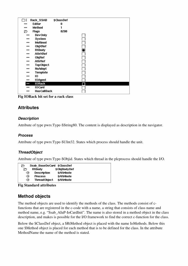
Fig IORack bit set for a rack class
Attributes
Description
Attribute of type pwrs:Type$String80. The content is displayed as description in the navigator.
Process
Attribute of type pwrs:Type$UInt32. States which process should handle the unit.
ThreadObject
Attribute of type pwrs:Type$Objid. States which thread in the plcprocess should handle the I/O.
Fig Standard attributes
Method objectsThe method objects are used to identify the methods of the class. The methods consist of cfunctions that are registered in the ccode with a name, a string that consists of class name and method name, e.g. “Ssab_AIuPIoCardInit”. The name is also stored in a method object in the class description, and makes is possible for the I/O framework to find the correct cfunction for the class.
Below the $ClassDef object, a $RtMethod object is placed with the name IoMethods. Below this one $Method object is placed for each method that is to be defined for the class. In the attribute MethodName the name of the method is stated.
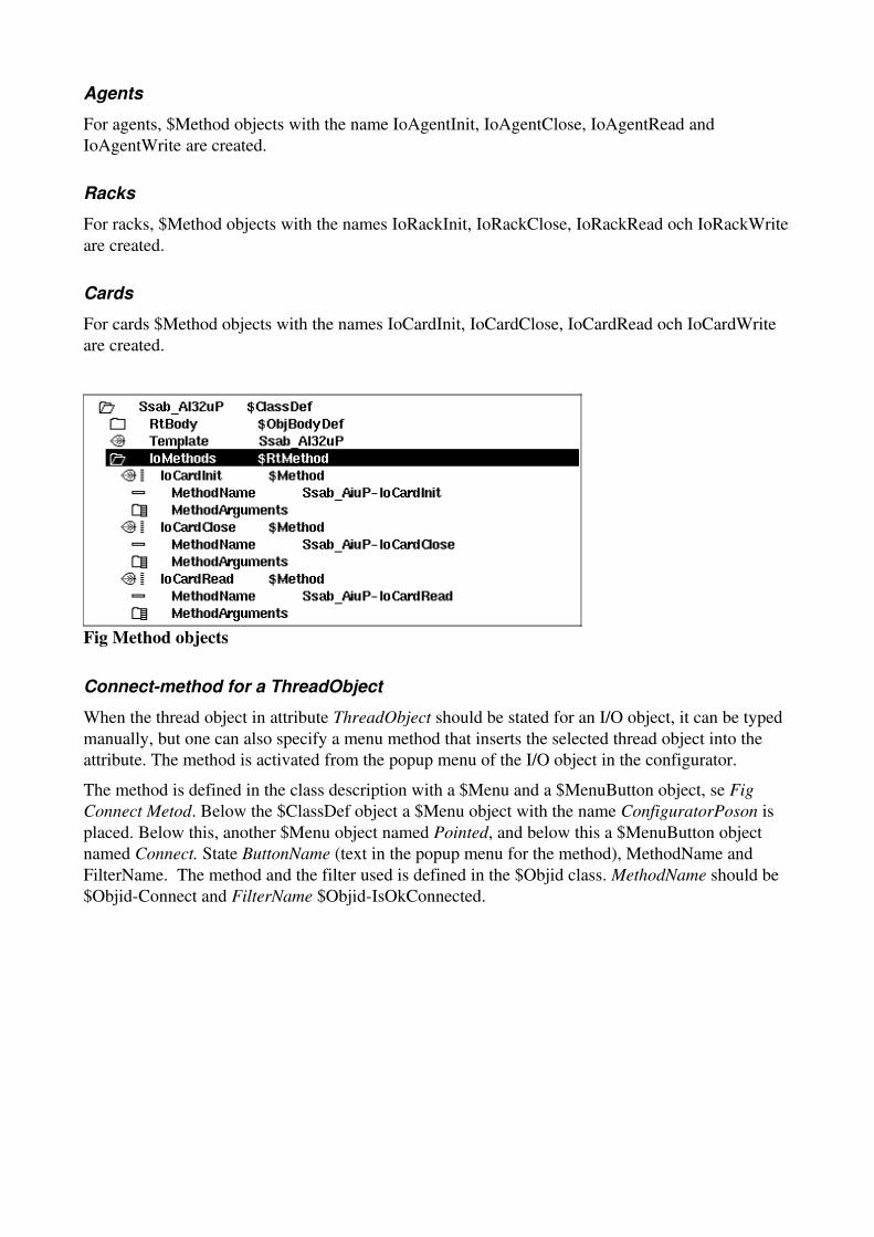
Agents
For agents, $Method objects with the name IoAgentInit, IoAgentClose, IoAgentRead and IoAgentWrite are created.
Racks
For racks, $Method objects with the names IoRackInit, IoRackClose, IoRackRead och IoRackWrite are created.
Cards
For cards $Method objects with the names IoCardInit, IoCardClose, IoCardRead och IoCardWrite are created.
Fig Method objects
Connectmethod for a ThreadObject
When the thread object in attribute ThreadObject should be stated for an I/O object, it can be typed manually, but one can also specify a menu method that inserts the selected thread object into the attribute. The method is activated from the popup menu of the I/O object in the configurator.
The method is defined in the class description with a $Menu and a $MenuButton object, se Fig Connect Metod. Below the $ClassDef object a $Menu object with the name ConfiguratorPoson is placed. Below this, another $Menu object named Pointed, and below this a $MenuButton object named Connect. State ButtonName (text in the popup menu for the method), MethodName and FilterName. The method and the filter used is defined in the $Objid class. MethodName should be $ObjidConnect and FilterName $ObjidIsOkConnected.
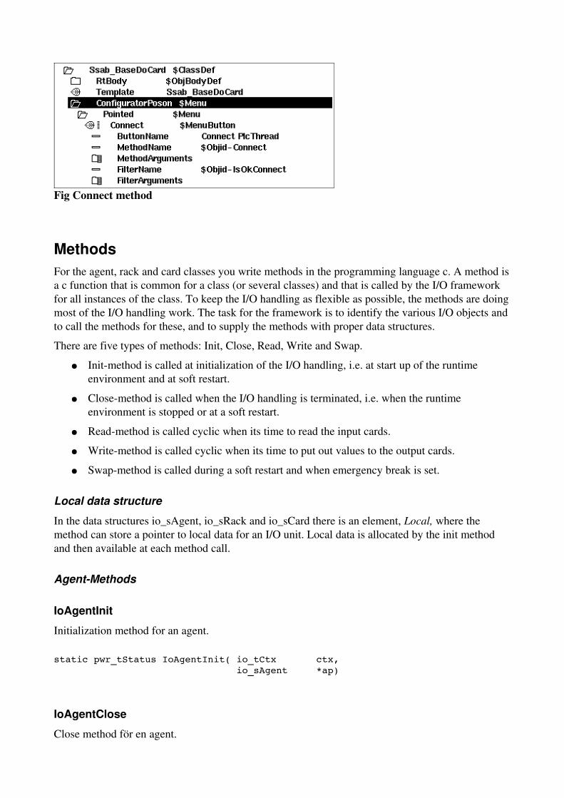
Fig Connect method
MethodsFor the agent, rack and card classes you write methods in the programming language c. A method is a c function that is common for a class (or several classes) and that is called by the I/O framework for all instances of the class. To keep the I/O handling as flexible as possible, the methods are doing most of the I/O handling work. The task for the framework is to identify the various I/O objects and to call the methods for these, and to supply the methods with proper data structures.
There are five types of methods: Init, Close, Read, Write and Swap.
● Initmethod is called at initialization of the I/O handling, i.e. at start up of the runtime environment and at soft restart.
● Closemethod is called when the I/O handling is terminated, i.e. when the runtime environment is stopped or at a soft restart.
● Readmethod is called cyclic when its time to read the input cards.
● Writemethod is called cyclic when its time to put out values to the output cards.
● Swapmethod is called during a soft restart and when emergency break is set.
Local data structure
In the data structures io_sAgent, io_sRack and io_sCard there is an element, Local, where the method can store a pointer to local data for an I/O unit. Local data is allocated by the init method and then available at each method call.
AgentMethods
IoAgentInit
Initialization method for an agent.
static pwr_tStatus IoAgentInit( io_tCtx ctx, io_sAgent *ap)
IoAgentClose
Close method för en agent.
static pwr_tStatus IoAgentClose( io_tCtx ctx, io_sAgent *ap)
IoAgentRead
Read method for an agent.static pwr_tStatus IoAgentRead( io_tCtx ctx, io_sAgent *ap)
IoAgentWrite
Write method for an agent.static pwr_tStatus IoAgentWrite( io_tCtx ctx, io_sAgent *ap)
IoAgentSwap
Swap method for an agent.static pwr_tStatus IoAgentSwap( io_tCtx ctx, io_sAgent *ap, io_eEvent event)
Rackmetoder
IoRackInitstatic pwr_tStatus IoRackInit( io_tCtx ctx, io_sAgent *ap, io_sRack *rp)
IoRackClosestatic pwr_tStatus IoRackClose( io_tCtx ctx, io_sAgent *ap, io_sRack *rp)
IoRackReadstatic pwr_tStatus IoRackRead( io_tCtx ctx, io_sAgent *ap, io_sRack *rp)
IoRackWritestatic pwr_tStatus IoRackWrite( io_tCtx ctx, io_sAgent *ap, io_sRack *rp)
IoRackSwapstatic pwr_tStatus IoRackSwap( io_tCtx ctx, io_sAgent *ap, io_sRack *rp, io_eEvent event)
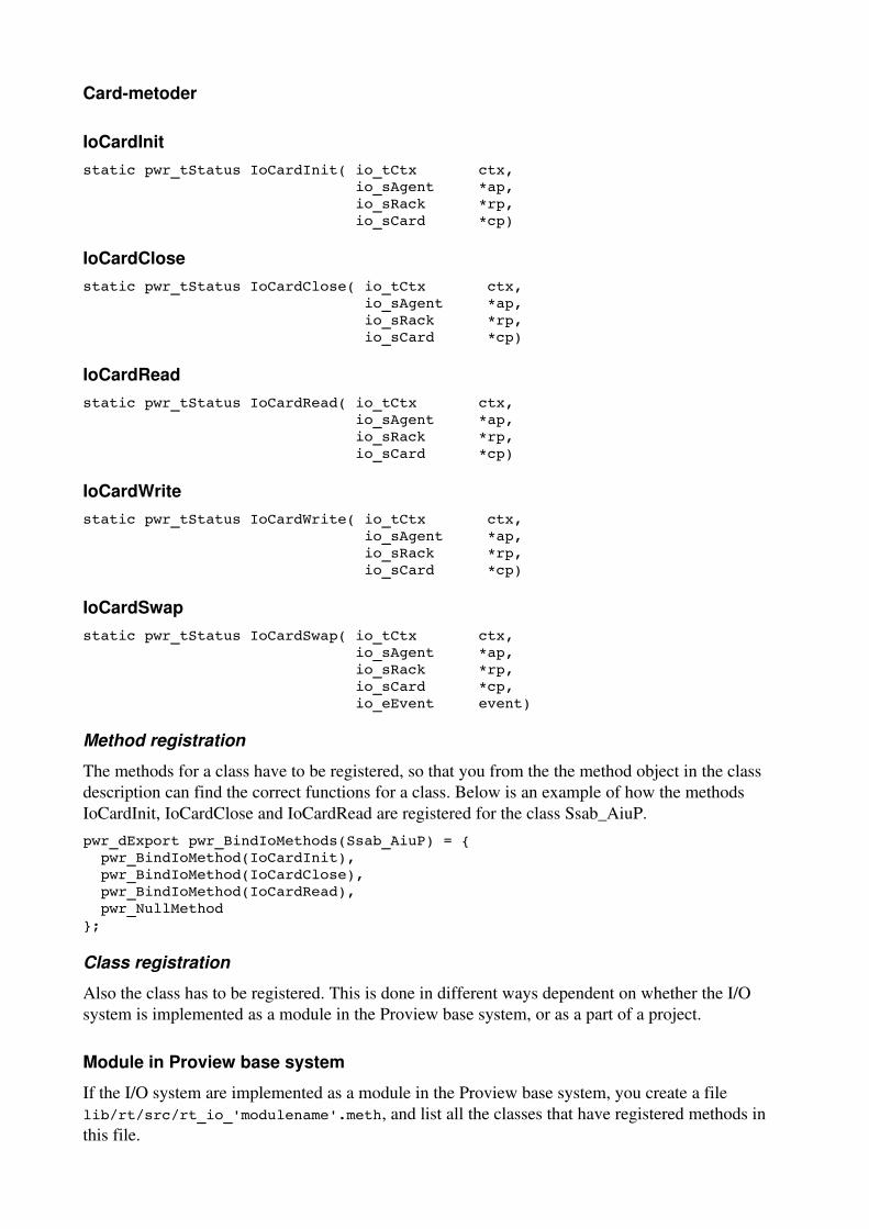
Cardmetoder
IoCardInitstatic pwr_tStatus IoCardInit( io_tCtx ctx, io_sAgent *ap, io_sRack *rp, io_sCard *cp)
IoCardClosestatic pwr_tStatus IoCardClose( io_tCtx ctx, io_sAgent *ap, io_sRack *rp, io_sCard *cp)
IoCardReadstatic pwr_tStatus IoCardRead( io_tCtx ctx, io_sAgent *ap, io_sRack *rp, io_sCard *cp)
IoCardWritestatic pwr_tStatus IoCardWrite( io_tCtx ctx, io_sAgent *ap, io_sRack *rp, io_sCard *cp)
IoCardSwapstatic pwr_tStatus IoCardSwap( io_tCtx ctx, io_sAgent *ap, io_sRack *rp, io_sCard *cp, io_eEvent event)
Method registration
The methods for a class have to be registered, so that you from the the method object in the class description can find the correct functions for a class. Below is an example of how the methods IoCardInit, IoCardClose and IoCardRead are registered for the class Ssab_AiuP.pwr_dExport pwr_BindIoMethods(Ssab_AiuP) = { pwr_BindIoMethod(IoCardInit), pwr_BindIoMethod(IoCardClose), pwr_BindIoMethod(IoCardRead), pwr_NullMethod};
Class registration
Also the class has to be registered. This is done in different ways dependent on whether the I/O system is implemented as a module in the Proview base system, or as a part of a project.
Module in Proview base system
If the I/O system are implemented as a module in the Proview base system, you create a file lib/rt/src/rt_io_'modulename'.meth, and list all the classes that have registered methods in this file.
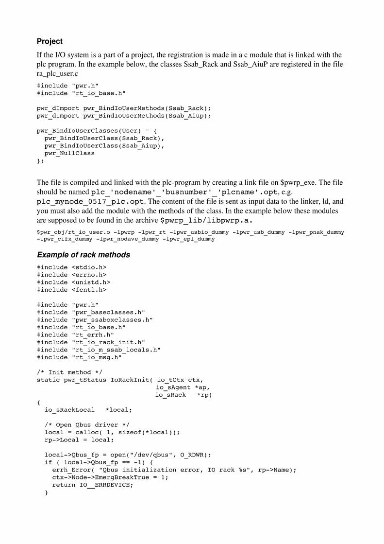
Project
If the I/O system is a part of a project, the registration is made in a c module that is linked with the plc program. In the example below, the classes Ssab_Rack and Ssab_AiuP are registered in the file ra_plc_user.c#include "pwr.h"#include "rt_io_base.h"
pwr_dImport pwr_BindIoUserMethods(Ssab_Rack);pwr_dImport pwr_BindIoUserMethods(Ssab_Aiup);
pwr_BindIoUserClasses(User) = { pwr_BindIoUserClass(Ssab_Rack), pwr_BindIoUserClass(Ssab_Aiup), pwr_NullClass};
The file is compiled and linked with the plcprogram by creating a link file on $pwrp_exe. The file should be named plc_'nodename'_'busnumber'_'plcname'.opt, e.g. plc_mynode_0517_plc.opt. The content of the file is sent as input data to the linker, ld, and you must also add the module with the methods of the class. In the example below these modules are supposed to be found in the archive $pwrp_lib/libpwrp.a.$pwr_obj/rt_io_user.o lpwrp lpwr_rt lpwr_usbio_dummy lpwr_usb_dummy lpwr_pnak_dummy lpwr_cifx_dummy lpwr_nodave_dummy lpwr_epl_dummy
Example of rack methods#include <stdio.h>#include <errno.h>#include <unistd.h>#include <fcntl.h>
#include "pwr.h"#include "pwr_baseclasses.h"#include "pwr_ssaboxclasses.h"#include "rt_io_base.h"#include "rt_errh.h"#include "rt_io_rack_init.h"#include "rt_io_m_ssab_locals.h"#include "rt_io_msg.h"
/* Init method */static pwr_tStatus IoRackInit( io_tCtx ctx,
io_sAgent *ap, io_sRack *rp)
{ io_sRackLocal *local;
/* Open Qbus driver */ local = calloc( 1, sizeof(*local)); rp>Local = local;
local>Qbus_fp = open("/dev/qbus", O_RDWR); if ( local>Qbus_fp == 1) { errh_Error( "Qbus initialization error, IO rack %s", rp>Name); ctx>Node>EmergBreakTrue = 1; return IO__ERRDEVICE; }

errh_Info( "Init of IO rack %s", rp>Name); return 1;}
/* Close method */static pwr_tStatus IoRackClose( io_tCtx ctx,
io_sAgent *ap, io_sRack *rp)
{ io_sRackLocal *local;
/* Close Qbus driver */ local = rp>Local;
close( local>Qbus_fp); free( (char *)local);
return 1;}
/* Every method to be exported to the workbench should be registered here. */
pwr_dExport pwr_BindIoMethods(Rack_SSAB) = { pwr_BindIoMethod(IoRackInit), pwr_BindIoMethod(IoRackClose), pwr_NullMethod};
Example of the methods of a digital input card#include <stdio.h>#include <errno.h>#include <unistd.h>#include <fcntl.h>#include <string.h>#include <stdlib.h>
#include "pwr.h"#include "rt_errh.h"#include "pwr_baseclasses.h"#include "pwr_ssaboxclasses.h"#include "rt_io_base.h"#include "rt_io_msg.h"#include "rt_io_filter_di.h"#include "rt_io_ssab.h"#include "rt_io_card_init.h"#include "rt_io_card_close.h"#include "rt_io_card_read.h"#include "qbus_io.h"#include "rt_io_m_ssab_locals.h"
/* Local data */typedef struct {
unsigned int Address[2];int Qbus_fp;struct { pwr_sClass_Di *sop[16]; void *Data[16]; pwr_tBoolean Found;} Filter[2];pwr_tTime ErrTime;
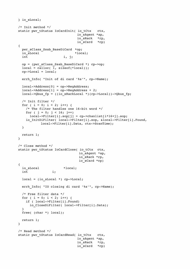
} io_sLocal;
/* Init method */static pwr_tStatus IoCardInit( io_tCtx ctx,
io_sAgent *ap, io_sRack *rp, io_sCard *cp)
{ pwr_sClass_Ssab_BaseDiCard *op; io_sLocal *local; int i, j;
op = (pwr_sClass_Ssab_BaseDiCard *) cp>op; local = calloc( 1, sizeof(*local)); cp>Local = local;
errh_Info( "Init of di card '%s'", cp>Name);
local>Address[0] = op>RegAddress; local>Address[1] = op>RegAddress + 2; local>Qbus_fp = ((io_sRackLocal *)(rp>Local))>Qbus_fp;
/* Init filter */ for ( i = 0; i < 2; i++) { /* The filter handles one 16bit word */ for ( j = 0; j < 16; j++) local>Filter[i].sop[j] = cp>chanlist[i*16+j].sop; io_InitDiFilter( local>Filter[i].sop, &local>Filter[i].Found,
local>Filter[i].Data, ctx>ScanTime); }
return 1;}
/* Close method */static pwr_tStatus IoCardClose( io_tCtx ctx,
io_sAgent *ap, io_sRack *rp, io_sCard *cp)
{ io_sLocal *local; int i;
local = (io_sLocal *) cp>Local;
errh_Info( "IO closing di card '%s'", cp>Name);
/* Free filter data */ for ( i = 0; i < 2; i++) { if ( local>Filter[i].Found) io_CloseDiFilter( local>Filter[i].Data); } free( (char *) local);
return 1;}
/* Read method */static pwr_tStatus IoCardRead( io_tCtx ctx,
io_sAgent *ap, io_sRack *rp, io_sCard *cp)
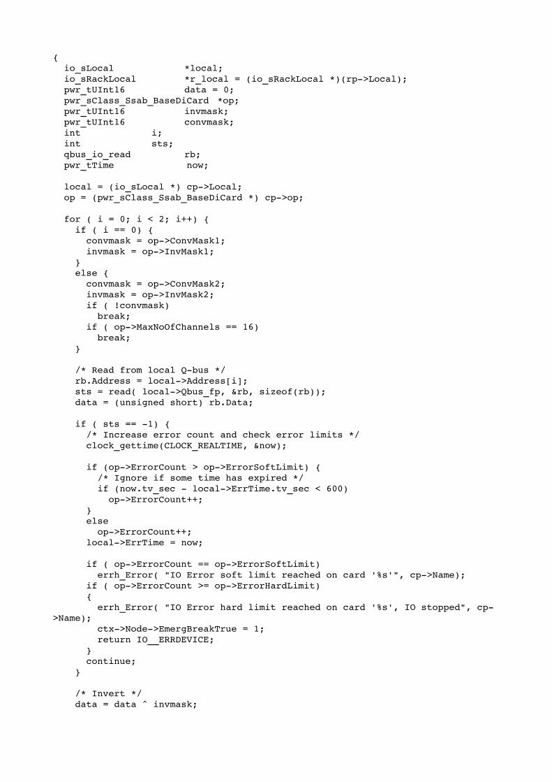
{ io_sLocal *local; io_sRackLocal *r_local = (io_sRackLocal *)(rp>Local); pwr_tUInt16 data = 0; pwr_sClass_Ssab_BaseDiCard *op; pwr_tUInt16 invmask; pwr_tUInt16 convmask; int i; int sts; qbus_io_read rb; pwr_tTime now;
local = (io_sLocal *) cp>Local; op = (pwr_sClass_Ssab_BaseDiCard *) cp>op;
for ( i = 0; i < 2; i++) { if ( i == 0) { convmask = op>ConvMask1; invmask = op>InvMask1; } else { convmask = op>ConvMask2; invmask = op>InvMask2; if ( !convmask) break; if ( op>MaxNoOfChannels == 16) break; } /* Read from local Qbus */ rb.Address = local>Address[i]; sts = read( local>Qbus_fp, &rb, sizeof(rb)); data = (unsigned short) rb.Data; if ( sts == 1) { /* Increase error count and check error limits */ clock_gettime(CLOCK_REALTIME, &now);
if (op>ErrorCount > op>ErrorSoftLimit) { /* Ignore if some time has expired */ if (now.tv_sec local>ErrTime.tv_sec < 600) op>ErrorCount++; } else op>ErrorCount++; local>ErrTime = now;
if ( op>ErrorCount == op>ErrorSoftLimit) errh_Error( "IO Error soft limit reached on card '%s'", cp>Name); if ( op>ErrorCount >= op>ErrorHardLimit) { errh_Error( "IO Error hard limit reached on card '%s', IO stopped", cp>Name); ctx>Node>EmergBreakTrue = 1; return IO__ERRDEVICE; } continue; }
/* Invert */ data = data ^ invmask;
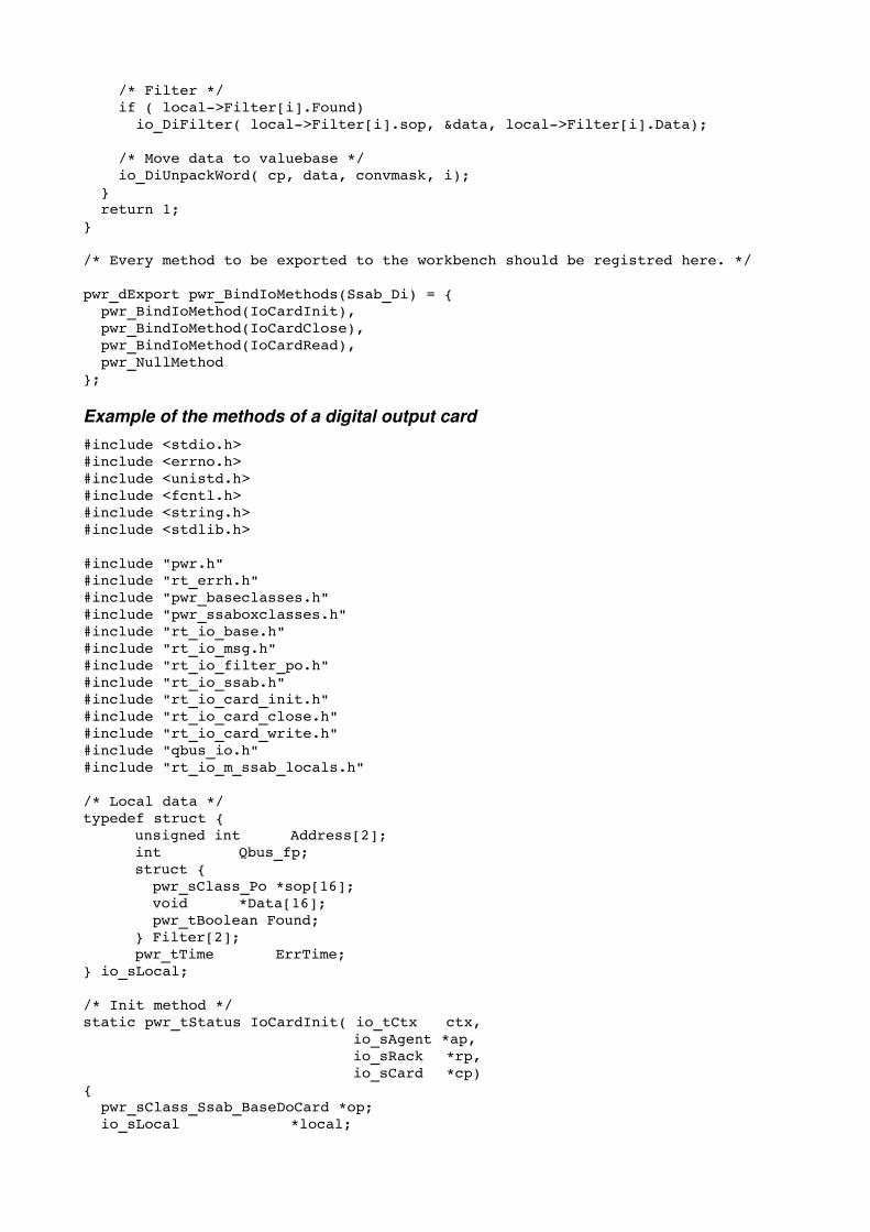
/* Filter */ if ( local>Filter[i].Found) io_DiFilter( local>Filter[i].sop, &data, local>Filter[i].Data);
/* Move data to valuebase */ io_DiUnpackWord( cp, data, convmask, i); } return 1;}
/* Every method to be exported to the workbench should be registred here. */
pwr_dExport pwr_BindIoMethods(Ssab_Di) = { pwr_BindIoMethod(IoCardInit), pwr_BindIoMethod(IoCardClose), pwr_BindIoMethod(IoCardRead), pwr_NullMethod};
Example of the methods of a digital output card#include <stdio.h>#include <errno.h>#include <unistd.h>#include <fcntl.h>#include <string.h>#include <stdlib.h>
#include "pwr.h"#include "rt_errh.h"#include "pwr_baseclasses.h"#include "pwr_ssaboxclasses.h"#include "rt_io_base.h"#include "rt_io_msg.h"#include "rt_io_filter_po.h"#include "rt_io_ssab.h"#include "rt_io_card_init.h"#include "rt_io_card_close.h"#include "rt_io_card_write.h"#include "qbus_io.h"#include "rt_io_m_ssab_locals.h"
/* Local data */typedef struct {
unsigned int Address[2];int Qbus_fp;struct { pwr_sClass_Po *sop[16]; void *Data[16]; pwr_tBoolean Found;} Filter[2];pwr_tTime ErrTime;
} io_sLocal;
/* Init method */static pwr_tStatus IoCardInit( io_tCtx ctx,
io_sAgent *ap, io_sRack *rp, io_sCard *cp)
{ pwr_sClass_Ssab_BaseDoCard *op; io_sLocal *local;
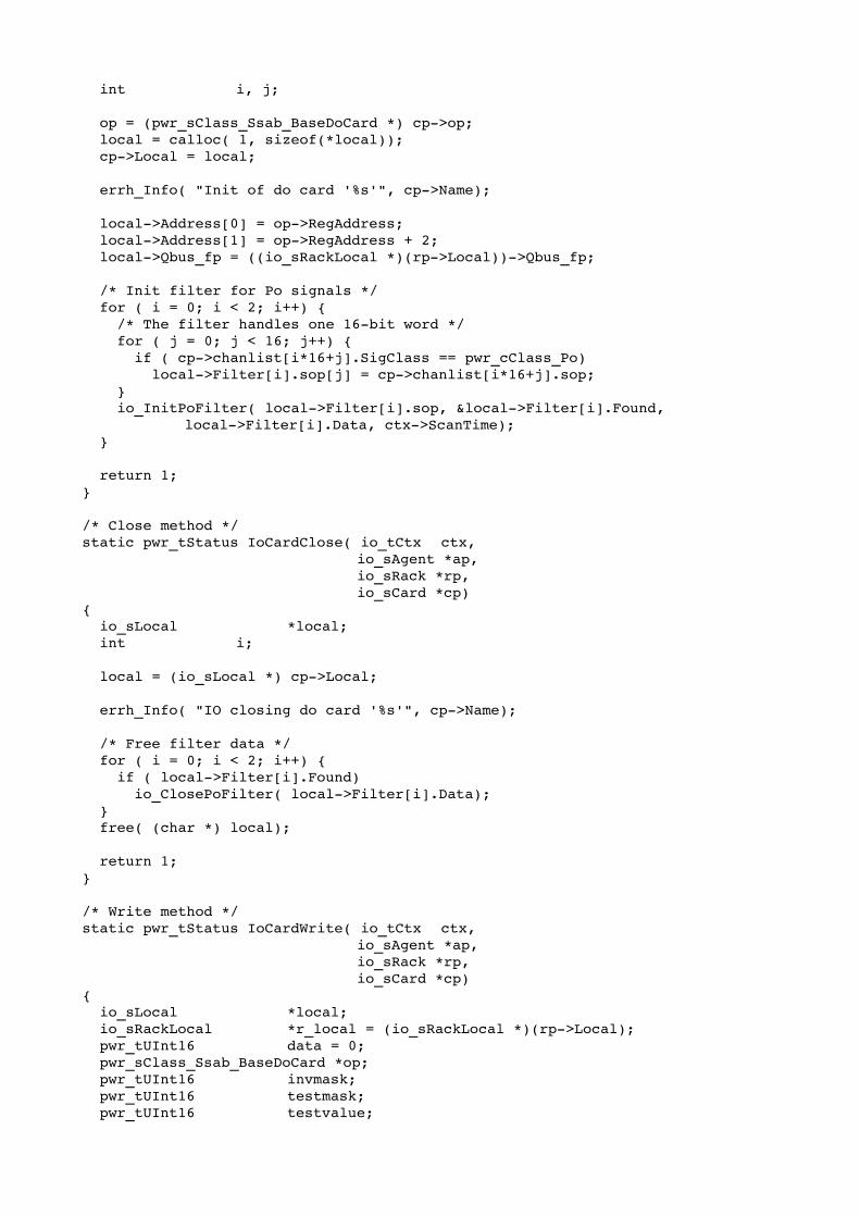
int i, j;
op = (pwr_sClass_Ssab_BaseDoCard *) cp>op; local = calloc( 1, sizeof(*local)); cp>Local = local;
errh_Info( "Init of do card '%s'", cp>Name);
local>Address[0] = op>RegAddress; local>Address[1] = op>RegAddress + 2; local>Qbus_fp = ((io_sRackLocal *)(rp>Local))>Qbus_fp;
/* Init filter for Po signals */ for ( i = 0; i < 2; i++) { /* The filter handles one 16bit word */ for ( j = 0; j < 16; j++) { if ( cp>chanlist[i*16+j].SigClass == pwr_cClass_Po) local>Filter[i].sop[j] = cp>chanlist[i*16+j].sop; } io_InitPoFilter( local>Filter[i].sop, &local>Filter[i].Found,
local>Filter[i].Data, ctx>ScanTime); }
return 1;}
/* Close method */static pwr_tStatus IoCardClose( io_tCtx ctx,
io_sAgent *ap, io_sRack *rp, io_sCard *cp)
{ io_sLocal *local; int i;
local = (io_sLocal *) cp>Local;
errh_Info( "IO closing do card '%s'", cp>Name);
/* Free filter data */ for ( i = 0; i < 2; i++) { if ( local>Filter[i].Found) io_ClosePoFilter( local>Filter[i].Data); } free( (char *) local);
return 1;}
/* Write method */static pwr_tStatus IoCardWrite( io_tCtx ctx,
io_sAgent *ap, io_sRack *rp, io_sCard *cp)
{ io_sLocal *local; io_sRackLocal *r_local = (io_sRackLocal *)(rp>Local); pwr_tUInt16 data = 0; pwr_sClass_Ssab_BaseDoCard *op; pwr_tUInt16 invmask; pwr_tUInt16 testmask; pwr_tUInt16 testvalue;
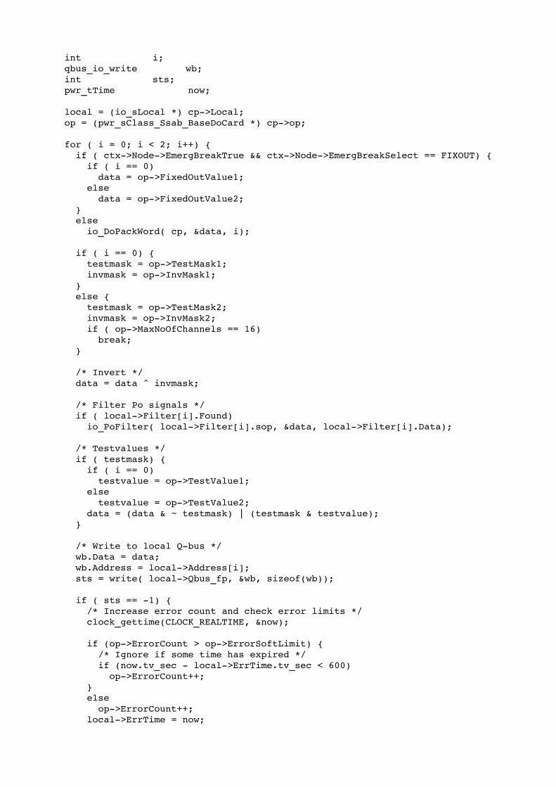
int i; qbus_io_write wb; int sts; pwr_tTime now;
local = (io_sLocal *) cp>Local; op = (pwr_sClass_Ssab_BaseDoCard *) cp>op;
for ( i = 0; i < 2; i++) { if ( ctx>Node>EmergBreakTrue && ctx>Node>EmergBreakSelect == FIXOUT) { if ( i == 0) data = op>FixedOutValue1; else data = op>FixedOutValue2; } else io_DoPackWord( cp, &data, i);
if ( i == 0) { testmask = op>TestMask1; invmask = op>InvMask1; } else { testmask = op>TestMask2; invmask = op>InvMask2; if ( op>MaxNoOfChannels == 16) break; }
/* Invert */ data = data ^ invmask;
/* Filter Po signals */ if ( local>Filter[i].Found) io_PoFilter( local>Filter[i].sop, &data, local>Filter[i].Data);
/* Testvalues */ if ( testmask) { if ( i == 0) testvalue = op>TestValue1; else testvalue = op>TestValue2; data = (data & ~ testmask) | (testmask & testvalue); }
/* Write to local Qbus */ wb.Data = data; wb.Address = local>Address[i]; sts = write( local>Qbus_fp, &wb, sizeof(wb));
if ( sts == 1) { /* Increase error count and check error limits */ clock_gettime(CLOCK_REALTIME, &now);
if (op>ErrorCount > op>ErrorSoftLimit) { /* Ignore if some time has expired */ if (now.tv_sec local>ErrTime.tv_sec < 600) op>ErrorCount++; } else op>ErrorCount++; local>ErrTime = now;
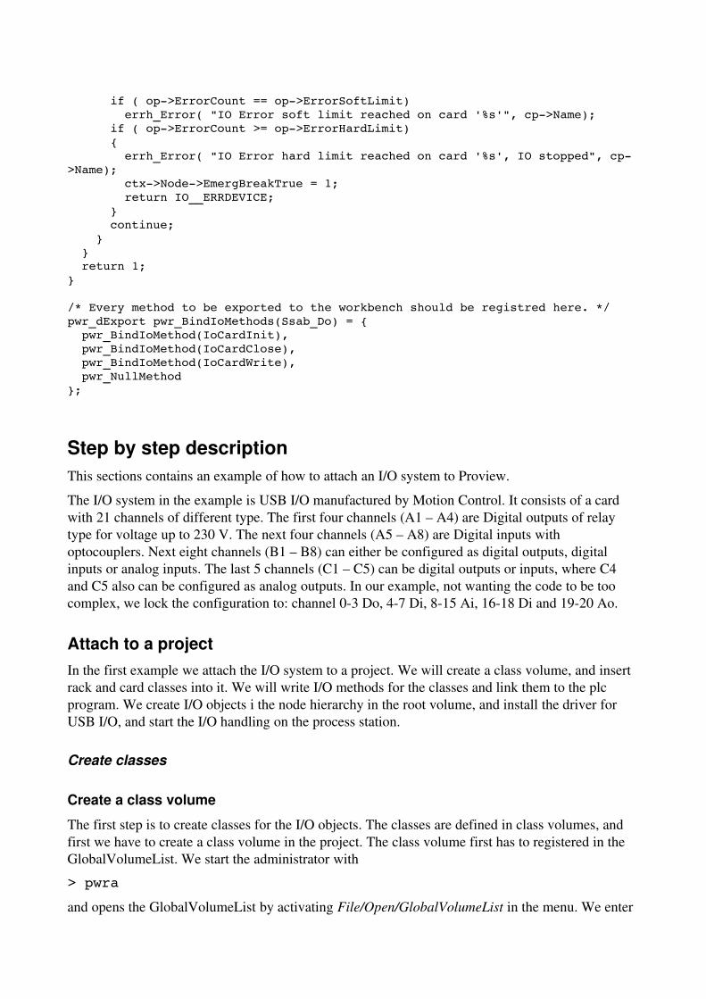
if ( op>ErrorCount == op>ErrorSoftLimit) errh_Error( "IO Error soft limit reached on card '%s'", cp>Name); if ( op>ErrorCount >= op>ErrorHardLimit) { errh_Error( "IO Error hard limit reached on card '%s', IO stopped", cp>Name); ctx>Node>EmergBreakTrue = 1; return IO__ERRDEVICE; } continue; } } return 1;}
/* Every method to be exported to the workbench should be registred here. */pwr_dExport pwr_BindIoMethods(Ssab_Do) = { pwr_BindIoMethod(IoCardInit), pwr_BindIoMethod(IoCardClose), pwr_BindIoMethod(IoCardWrite), pwr_NullMethod};
Step by step descriptionThis sections contains an example of how to attach an I/O system to Proview.
The I/O system in the example is USB I/O manufactured by Motion Control. It consists of a card with 21 channels of different type. The first four channels (A1 – A4) are Digital outputs of relay type for voltage up to 230 V. The next four channels (A5 – A8) are Digital inputs with optocouplers. Next eight channels (B1 – B8) can either be configured as digital outputs, digital inputs or analog inputs. The last 5 channels (C1 – C5) can be digital outputs or inputs, where C4 and C5 also can be configured as analog outputs. In our example, not wanting the code to be too complex, we lock the configuration to: channel 03 Do, 47 Di, 815 Ai, 1618 Di and 1920 Ao.
Attach to a projectIn the first example we attach the I/O system to a project. We will create a class volume, and insert rack and card classes into it. We will write I/O methods for the classes and link them to the plc program. We create I/O objects i the node hierarchy in the root volume, and install the driver for USB I/O, and start the I/O handling on the process station.
Create classes
Create a class volume
The first step is to create classes for the I/O objects. The classes are defined in class volumes, and first we have to create a class volume in the project. The class volume first has to registered in the GlobalVolumeList. We start the administrator with
> pwra
and opens the GlobalVolumeList by activating File/Open/GlobalVolumeList in the menu. We enter
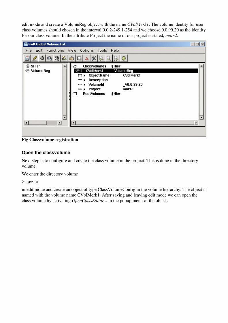
edit mode and create a VolumeReg object with the name CVolMerk1. The volume identity for user class volumes should chosen in the interval 0.0.2249.1254 and we choose 0.0.99.20 as the identity for our class volume. In the attribute Project the name of our project is stated, mars2.
Fig Classvolume registration
Open the classvolume
Next step is to configure and create the class volume in the project. This is done in the directory volume.
We enter the directory volume
> pwrs
in edit mode and create an object of type ClassVolumeConfig in the volume hierarchy. The object is named with the volume name CVolMerk1. After saving and leaving edit mode we can open the class volume by activating OpenClassEditor... in the popup menu of the object.
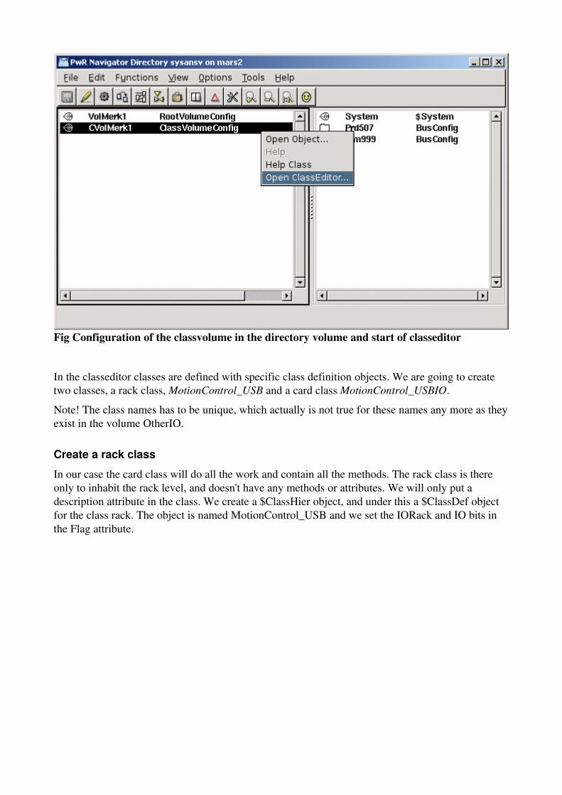
Fig Configuration of the classvolume in the directory volume and start of classeditor
In the classeditor classes are defined with specific class definition objects. We are going to create two classes, a rack class, MotionControl_USB and a card class MotionControl_USBIO.
Note! The class names has to be unique, which actually is not true for these names any more as they exist in the volume OtherIO.
Create a rack class
In our case the card class will do all the work and contain all the methods. The rack class is there only to inhabit the rack level, and doesn't have any methods or attributes. We will only put a description attribute in the class. We create a $ClassHier object, and under this a $ClassDef object for the class rack. The object is named MotionControl_USB and we set the IORack and IO bits in the Flag attribute.
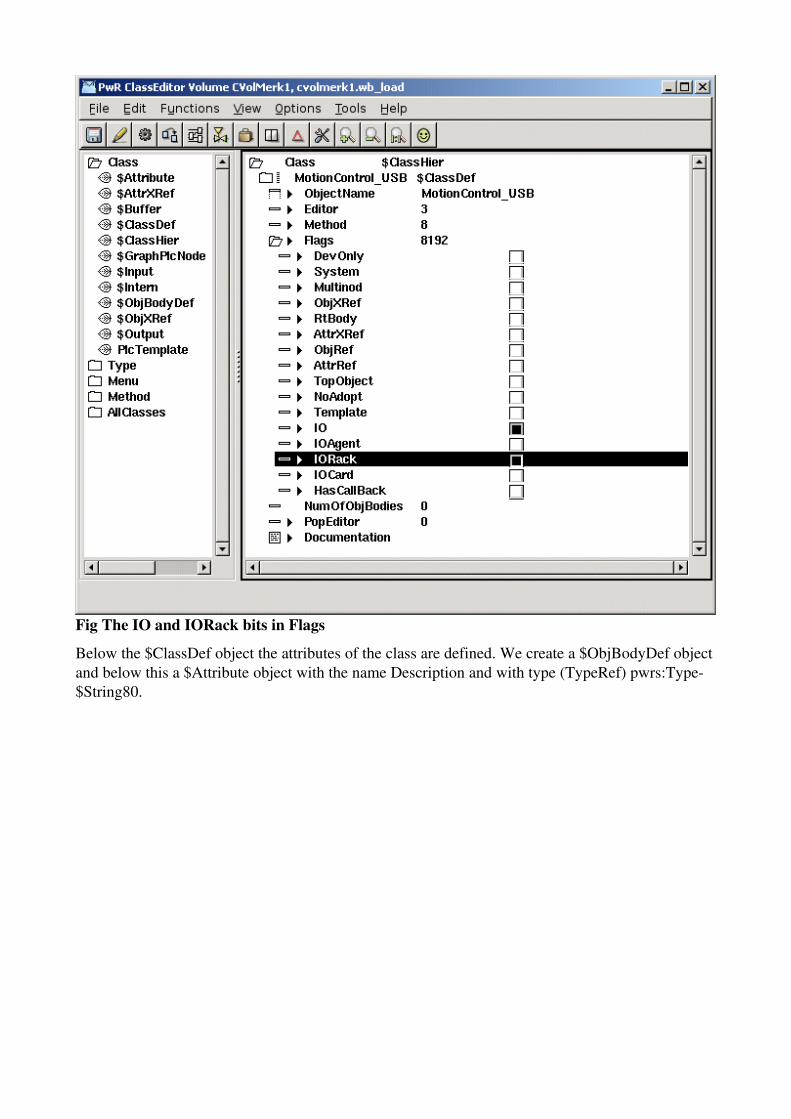
Fig The IO and IORack bits in Flags
Below the $ClassDef object the attributes of the class are defined. We create a $ObjBodyDef object and below this a $Attribute object with the name Description and with type (TypeRef) pwrs:Type$String80.
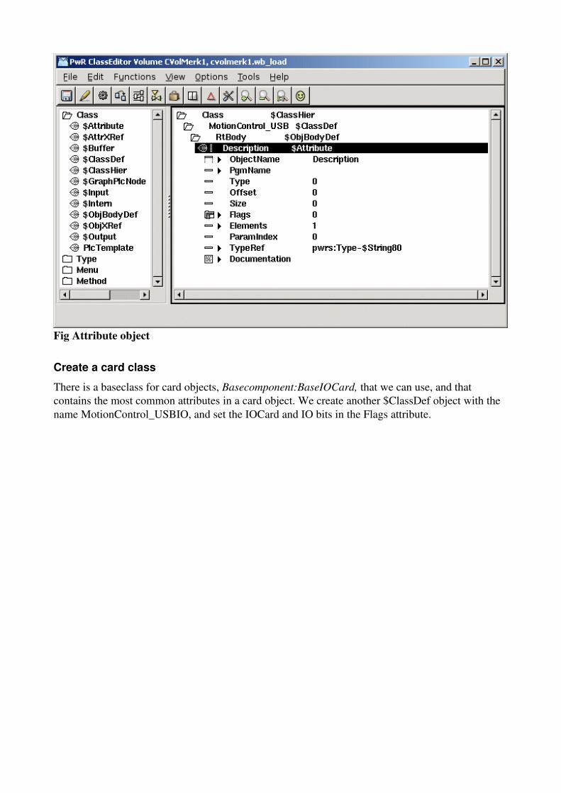
Fig Attribute object
Create a card class
There is a baseclass for card objects, Basecomponent:BaseIOCard, that we can use, and that contains the most common attributes in a card object. We create another $ClassDef object with the name MotionControl_USBIO, and set the IOCard and IO bits in the Flags attribute.
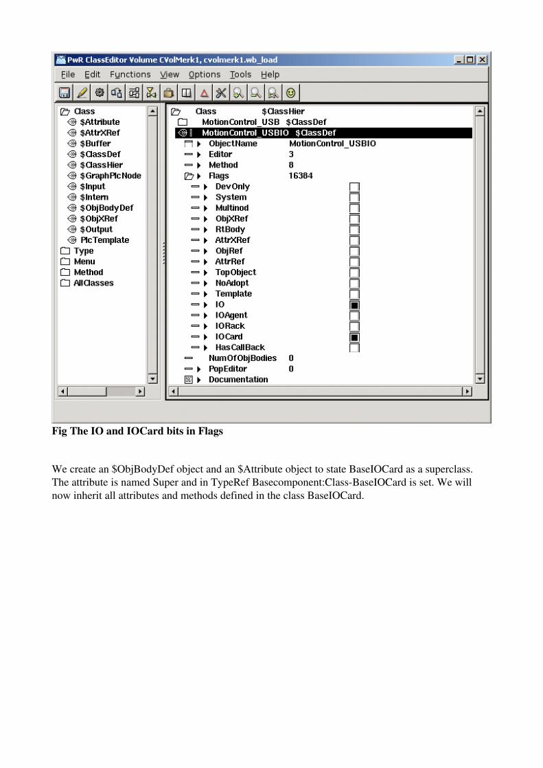
Fig The IO and IOCard bits in Flags
We create an $ObjBodyDef object and an $Attribute object to state BaseIOCard as a superclass. The attribute is named Super and in TypeRef Basecomponent:ClassBaseIOCard is set. We will now inherit all attributes and methods defined in the class BaseIOCard.
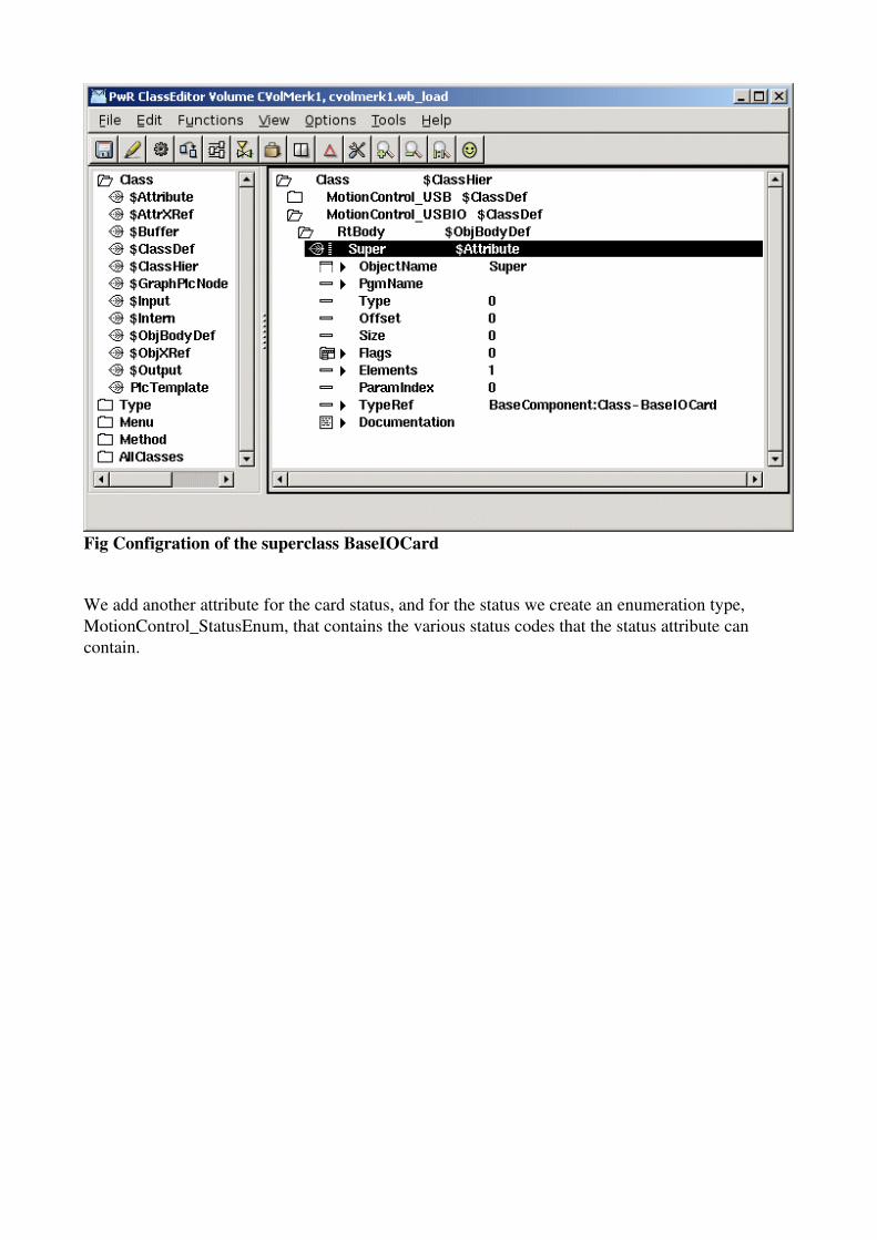
Fig Configration of the superclass BaseIOCard
We add another attribute for the card status, and for the status we create an enumeration type, MotionControl_StatusEnum, that contains the various status codes that the status attribute can contain.
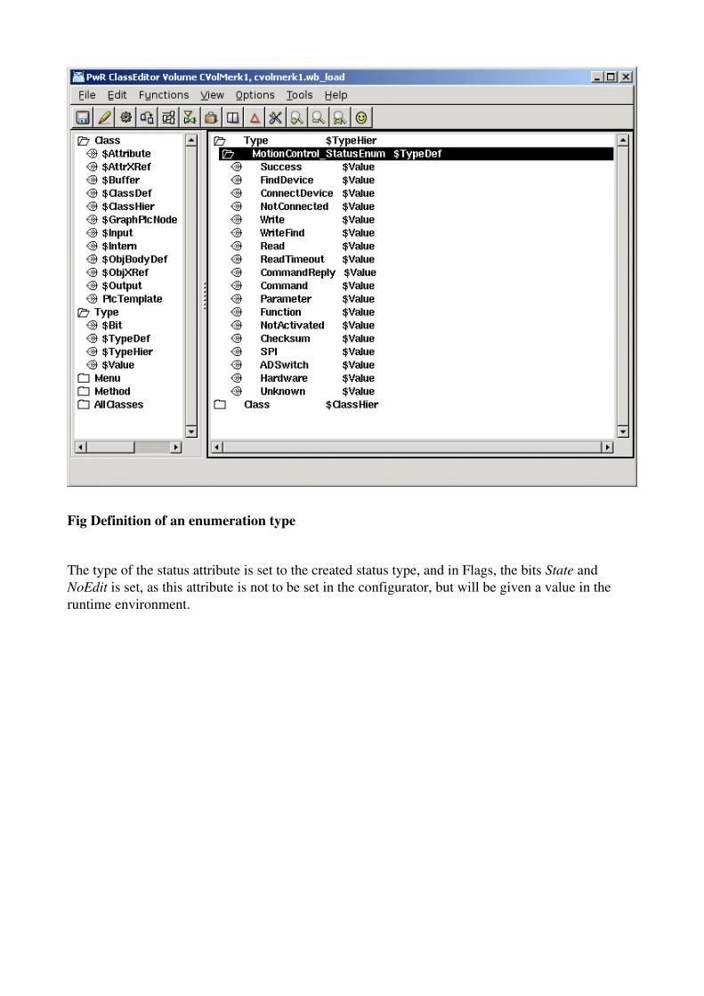
Fig Definition of an enumeration type
The type of the status attribute is set to the created status type, and in Flags, the bits State and NoEdit is set, as this attribute is not to be set in the configurator, but will be given a value in the runtime environment.
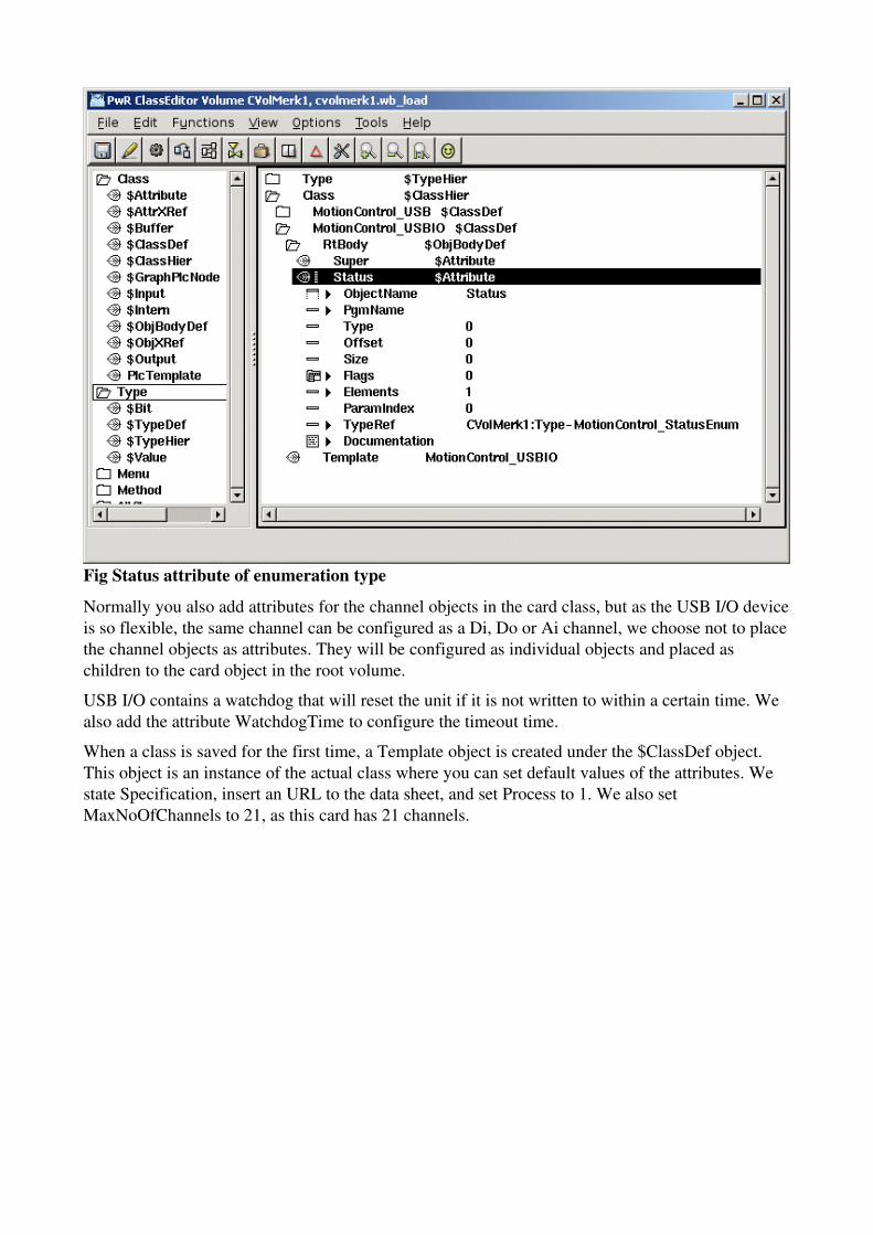
Fig Status attribute of enumeration type
Normally you also add attributes for the channel objects in the card class, but as the USB I/O device is so flexible, the same channel can be configured as a Di, Do or Ai channel, we choose not to place the channel objects as attributes. They will be configured as individual objects and placed as children to the card object in the root volume.
USB I/O contains a watchdog that will reset the unit if it is not written to within a certain time. We also add the attribute WatchdogTime to configure the timeout time.
When a class is saved for the first time, a Template object is created under the $ClassDef object. This object is an instance of the actual class where you can set default values of the attributes. We state Specification, insert an URL to the data sheet, and set Process to 1. We also set MaxNoOfChannels to 21, as this card has 21 channels.
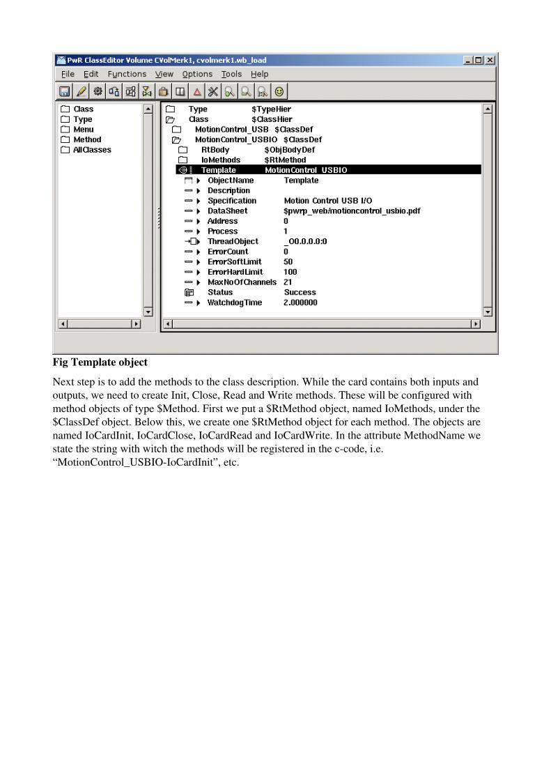
Fig Template object
Next step is to add the methods to the class description. While the card contains both inputs and outputs, we need to create Init, Close, Read and Write methods. These will be configured with method objects of type $Method. First we put a $RtMethod object, named IoMethods, under the $ClassDef object. Below this, we create one $RtMethod object for each method. The objects are named IoCardInit, IoCardClose, IoCardRead and IoCardWrite. In the attribute MethodName we state the string with witch the methods will be registered in the ccode, i.e. “MotionControl_USBIOIoCardInit”, etc.
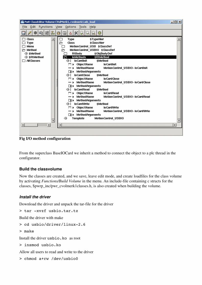
Fig I/O method configuration
From the superclass BaseIOCard we inherit a method to connect the object to a plc thread in the configurator.
Build the classvolume
Now the classes are created, and we save, leave edit mode, and create loadfiles for the class volume by activating Functions/Build Volume in the menu. An includefile containing c structs for the classes, $pwrp_inc/pwr_cvolmerk1classes.h, is also created when building the volume.
Install the driver
Download the driver and unpack the tarfile for the driver
> tar xvzf usbio.tar.tz
Build the driver with make
> cd usbio/driver/linux2.6
> make
Install the driver usbio.ko as root
> insmod usbio.ko
Allow all users to read and write to the driver
> chmod a+rw /dev/usbio0

Write methodsThe next step is to write the ccode for the methods.
The cfile ra_io_m_motioncontrol_usbio.c are created on $pwrp_src.
As Proview has a GPL license, also the code for the methods has to be GPL licensed if the program is distributed to other parties. We therefor put a GPL header in the beginning of the file.
To simplify the code we limit our use of USB I/O to a configuration where channel 03 are digital outputs, 47 digital inputs, 815 analog inputs, 1618 digital inputs and 1920 analog outputs.
ra_io_m_motioncontrol_usbio.c/* * Proview $Id$ * Copyright (C) 2005 SSAB Oxelösund. * * This program is free software; you can redistribute it and/or * modify it under the terms of the GNU General Public License as * published by the Free Software Foundation, either version 2 of * the License, or (at your option) any later version. * * This program is distributed in the hope that it will be useful * but WITHOUT ANY WARRANTY; without even the implied warranty of * MERCHANTABILITY or FITNESS FOR A PARTICULAR PURPOSE. See the * GNU General Public License for more details. * * You should have received a copy of the GNU General Public License * along with the program, if not, write to the Free Software * Foundation, Inc., 675 Mass Ave, Cambridge, MA 02139, USA. */
#include "pwr.h"#include "pwr_basecomponentclasses.h"#include "pwr_cvolmerk1classes.h"#include "rt_io_base.h"#include "rt_io_card_init.h"#include "rt_io_card_close.h"#include "rt_io_card_read.h"#include "rt_io_card_write.h"#include "rt_io_msg.h"#include "libusbio.h"
typedef struct { int USB_Handle;} io_sLocal;
// Init methodstatic pwr_tStatus IoCardInit( io_tCtx ctx, io_sAgent *ap, io_sRack *rp, io_sCard *cp){ int i; int timeout; io_sLocal *local; pwr_sClass_MotionControl_USBIO *op = (pwr_sClass_MotionControl_USBIO *)cp>op;
local = (io_sLocal *) calloc( 1, sizeof(io_sLocal)); cp>Local = local;
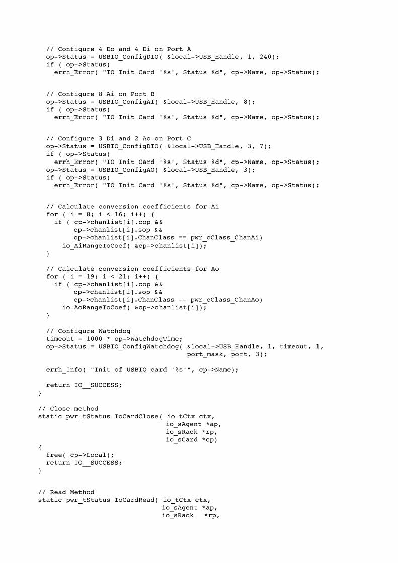
// Configure 4 Do and 4 Di on Port A op>Status = USBIO_ConfigDIO( &local>USB_Handle, 1, 240); if ( op>Status) errh_Error( "IO Init Card '%s', Status %d", cp>Name, op>Status);
// Configure 8 Ai on Port B op>Status = USBIO_ConfigAI( &local>USB_Handle, 8); if ( op>Status) errh_Error( "IO Init Card '%s', Status %d", cp>Name, op>Status);
// Configure 3 Di and 2 Ao on Port C op>Status = USBIO_ConfigDIO( &local>USB_Handle, 3, 7); if ( op>Status) errh_Error( "IO Init Card '%s', Status %d", cp>Name, op>Status); op>Status = USBIO_ConfigAO( &local>USB_Handle, 3); if ( op>Status) errh_Error( "IO Init Card '%s', Status %d", cp>Name, op>Status);
// Calculate conversion coefficients for Ai for ( i = 8; i < 16; i++) { if ( cp>chanlist[i].cop &&
cp>chanlist[i].sop && cp>chanlist[i].ChanClass == pwr_cClass_ChanAi)
io_AiRangeToCoef( &cp>chanlist[i]); }
// Calculate conversion coefficients for Ao for ( i = 19; i < 21; i++) { if ( cp>chanlist[i].cop &&
cp>chanlist[i].sop && cp>chanlist[i].ChanClass == pwr_cClass_ChanAo)
io_AoRangeToCoef( &cp>chanlist[i]); }
// Configure Watchdog timeout = 1000 * op>WatchdogTime; op>Status = USBIO_ConfigWatchdog( &local>USB_Handle, 1, timeout, 1, port_mask, port, 3);
errh_Info( "Init of USBIO card '%s'", cp>Name);
return IO__SUCCESS;}
// Close methodstatic pwr_tStatus IoCardClose( io_tCtx ctx,
io_sAgent *ap, io_sRack *rp, io_sCard *cp)
{ free( cp>Local); return IO__SUCCESS;}
// Read Methodstatic pwr_tStatus IoCardRead( io_tCtx ctx,
io_sAgent *ap, io_sRack *rp,
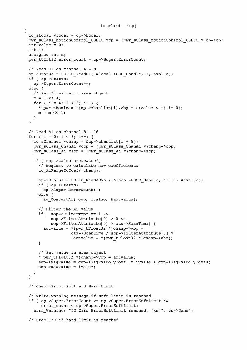
io_sCard *cp){ io_sLocal *local = cp>Local; pwr_sClass_MotionControl_USBIO *op = (pwr_sClass_MotionControl_USBIO *)cp>op; int value = 0; int i; unsigned int m; pwr_tUInt32 error_count = op>Super.ErrorCount;
// Read Di on channel 4 8 op>Status = USBIO_ReadDI( &local>USB_Handle, 1, &value); if ( op>Status) op>Super.ErrorCount++; else { // Set Di value in area object m = 1 << 4; for ( i = 4; i < 8; i++) {
*(pwr_tBoolean *)cp>chanlist[i].vbp = ((value & m) != 0);m = m << 1;
} }
// Read Ai on channel 8 16 for ( i = 0; i < 8; i++) { io_sChannel *chanp = &cp>chanlist[i + 8]; pwr_sClass_ChanAi *cop = (pwr_sClass_ChanAi *)chanp>cop; pwr_sClass_Ai *sop = (pwr_sClass_Ai *)chanp>sop;
if ( cop>CalculateNewCoef)// Request to calculate new coefficients
io_AiRangeToCoef( chanp);
op>Status = USBIO_ReadADVal( &local>USB_Handle, i + 1, &ivalue); if ( op>Status)
op>Super.ErrorCount++;else { io_ConvertAi( cop, ivalue, &actvalue);
// Filter the Ai valueif ( sop>FilterType == 1 && sop>FilterAttribute[0] > 0 && sop>FilterAttribute[0] > ctx>ScanTime) { actvalue = *(pwr_tFloat32 *)chanp>vbp +
ctx>ScanTime / sop>FilterAttribute[0] * (actvalue *(pwr_tFloat32 *)chanp>vbp);}
// Set value in area object*(pwr_tFloat32 *)chanp>vbp = actvalue;sop>SigValue = cop>SigValPolyCoef1 * ivalue + cop>SigValPolyCoef0;sop>RawValue = ivalue;
} }
// Check Error Soft and Hard Limit
// Write warning message if soft limit is reached if ( op>Super.ErrorCount >= op>Super.ErrorSoftLimit && error_count < op>Super.ErrorSoftLimit) errh_Warning( "IO Card ErrorSoftLimit reached, '%s'", cp>Name); // Stop I/O if hard limit is reached
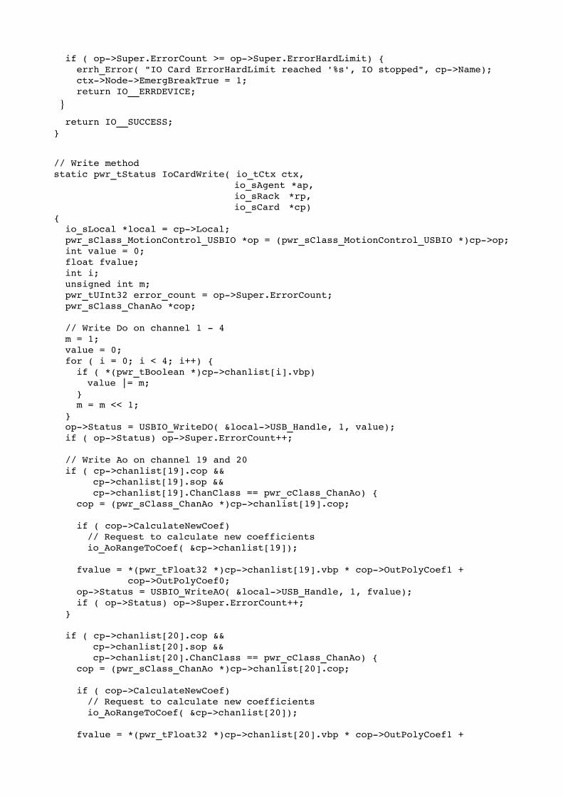
if ( op>Super.ErrorCount >= op>Super.ErrorHardLimit) { errh_Error( "IO Card ErrorHardLimit reached '%s', IO stopped", cp>Name); ctx>Node>EmergBreakTrue = 1; return IO__ERRDEVICE; } return IO__SUCCESS;}
// Write methodstatic pwr_tStatus IoCardWrite( io_tCtx ctx,
io_sAgent *ap, io_sRack *rp, io_sCard *cp)
{ io_sLocal *local = cp>Local; pwr_sClass_MotionControl_USBIO *op = (pwr_sClass_MotionControl_USBIO *)cp>op; int value = 0; float fvalue; int i; unsigned int m; pwr_tUInt32 error_count = op>Super.ErrorCount; pwr_sClass_ChanAo *cop;
// Write Do on channel 1 4 m = 1; value = 0; for ( i = 0; i < 4; i++) { if ( *(pwr_tBoolean *)cp>chanlist[i].vbp)
value |= m; } m = m << 1; } op>Status = USBIO_WriteDO( &local>USB_Handle, 1, value); if ( op>Status) op>Super.ErrorCount++;
// Write Ao on channel 19 and 20 if ( cp>chanlist[19].cop &&
cp>chanlist[19].sop && cp>chanlist[19].ChanClass == pwr_cClass_ChanAo) {
cop = (pwr_sClass_ChanAo *)cp>chanlist[19].cop;
if ( cop>CalculateNewCoef)// Request to calculate new coefficientsio_AoRangeToCoef( &cp>chanlist[19]);
fvalue = *(pwr_tFloat32 *)cp>chanlist[19].vbp * cop>OutPolyCoef1 + cop>OutPolyCoef0; op>Status = USBIO_WriteAO( &local>USB_Handle, 1, fvalue); if ( op>Status) op>Super.ErrorCount++; } if ( cp>chanlist[20].cop &&
cp>chanlist[20].sop && cp>chanlist[20].ChanClass == pwr_cClass_ChanAo) {
cop = (pwr_sClass_ChanAo *)cp>chanlist[20].cop;
if ( cop>CalculateNewCoef)// Request to calculate new coefficientsio_AoRangeToCoef( &cp>chanlist[20]);
fvalue = *(pwr_tFloat32 *)cp>chanlist[20].vbp * cop>OutPolyCoef1 +

cop>OutPolyCoef0; op>Status = USBIO_WriteAO( &local>USB_Handle, 2, fvalue); if ( op>Status) op>Super.ErrorCount++; }
// Check Error Soft and Hard Limit
// Write warning message if soft limit is reached if ( op>Super.ErrorCount >= op>Super.ErrorSoftLimit && error_count < op>Super.ErrorSoftLimit) errh_Warning( "IO Card ErrorSoftLimit reached, '%s'", cp>Name); // Stop I/O if hard limit is reached if ( op>Super.ErrorCount >= op>Super.ErrorHardLimit) { errh_Error( "IO Card ErrorHardLimit reached '%s', IO stopped", cp>Name); ctx>Node>EmergBreakTrue = 1; return IO__ERRDEVICE; }
return IO__SUCCESS;}
// Every method should be registred here
pwr_dExport pwr_BindIoUserMethods(MotionControl_USBIO) = { pwr_BindIoUserMethod(IoCardInit), pwr_BindIoUserMethod(IoCardClose), pwr_BindIoUserMethod(IoCardRead), pwr_BindIoUserMethod(IoCardWrite), pwr_NullMethod};
Class registration
To make it possible for the I/O framework to find the methods of the class, the class has to be registered. This is done by creating the file $pwrp_src/rt_io_user.c. You use the macros pwr_BindIoUserMethods and pwr_BindIoUserClass for each class that contains methods.
rt_io_user.c#include "pwr.h"#include "rt_io_base.h"
pwr_dImport pwr_BindIoUserMethods(MotionControl_USBIO);
pwr_BindIoUserClasses(User) = { pwr_BindIoUserClass(MotionControl_USBIO), pwr_NullClass};
Makefile
To compile the cfiles we create a makefile on $pwrp_src, $pwrp_src/makefile. This will compile ra_io_m_motioncontro_usbio.c and rt_io_user.c, and place the object modules on the directory $pwrp_obj.
makefilemars2_top : mars2
include $(pwr_exe)/pwrp_rules.mk
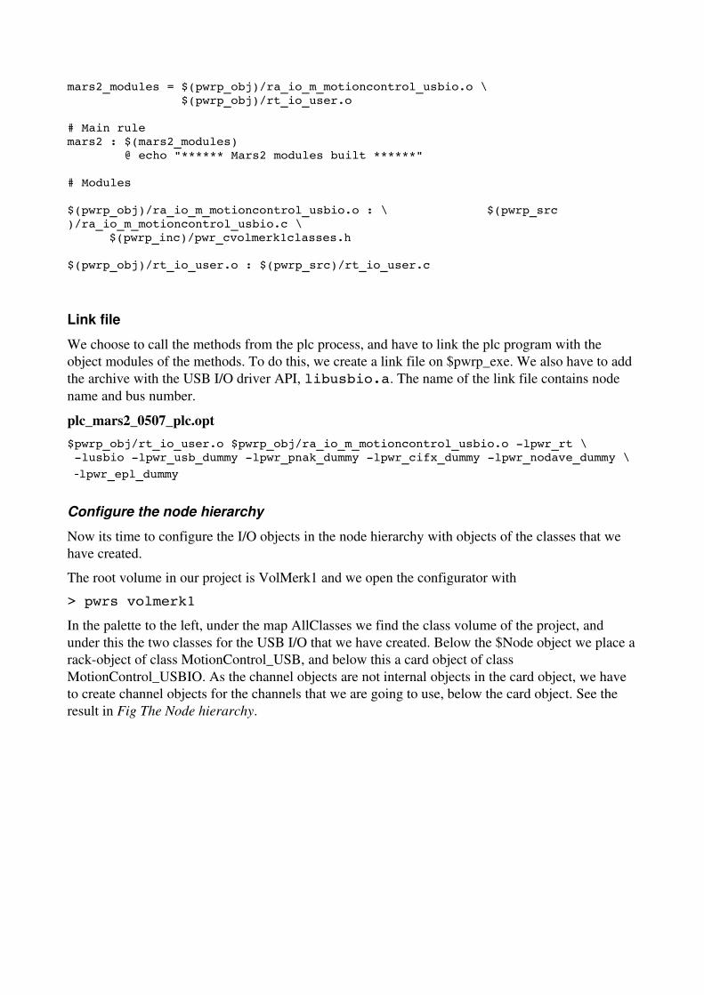
mars2_modules = $(pwrp_obj)/ra_io_m_motioncontrol_usbio.o \ $(pwrp_obj)/rt_io_user.o
# Main rulemars2 : $(mars2_modules) @ echo "****** Mars2 modules built ******"
# Modules
$(pwrp_obj)/ra_io_m_motioncontrol_usbio.o : \ $(pwrp_src)/ra_io_m_motioncontrol_usbio.c \
$(pwrp_inc)/pwr_cvolmerk1classes.h
$(pwrp_obj)/rt_io_user.o : $(pwrp_src)/rt_io_user.c
Link file
We choose to call the methods from the plc process, and have to link the plc program with the object modules of the methods. To do this, we create a link file on $pwrp_exe. We also have to add the archive with the USB I/O driver API, libusbio.a. The name of the link file contains node name and bus number.
plc_mars2_0507_plc.opt$pwrp_obj/rt_io_user.o $pwrp_obj/ra_io_m_motioncontrol_usbio.o lpwr_rt \ lusbio lpwr_usb_dummy lpwr_pnak_dummy lpwr_cifx_dummy lpwr_nodave_dummy \ lpwr_epl_dummy
Configure the node hierarchy
Now its time to configure the I/O objects in the node hierarchy with objects of the classes that we have created.
The root volume in our project is VolMerk1 and we open the configurator with
> pwrs volmerk1
In the palette to the left, under the map AllClasses we find the class volume of the project, and under this the two classes for the USB I/O that we have created. Below the $Node object we place a rackobject of class MotionControl_USB, and below this a card object of class MotionControl_USBIO. As the channel objects are not internal objects in the card object, we have to create channel objects for the channels that we are going to use, below the card object. See the result in Fig The Node hierarchy.
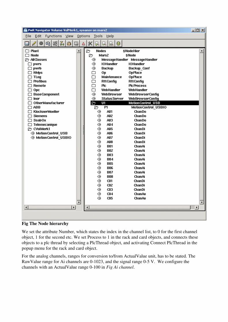
Fig The Node hierarchy
We set the attribute Number, which states the index in the channel list, to 0 for the first channel object, 1 for the second etc. We set Process to 1 in the rack and card objects, and connects these objects to a plc thread by selecting a PlcThread object, and activating Connect PlcThread in the popup menu for the rack and card object.
For the analog channels, ranges for conversion to/from ActualValue unit, has to be stated. The RawValue range for Ai channels are 01023, and the signal range 05 V. We configure the channels with an ActualValue range 0100 in Fig Ai channel.
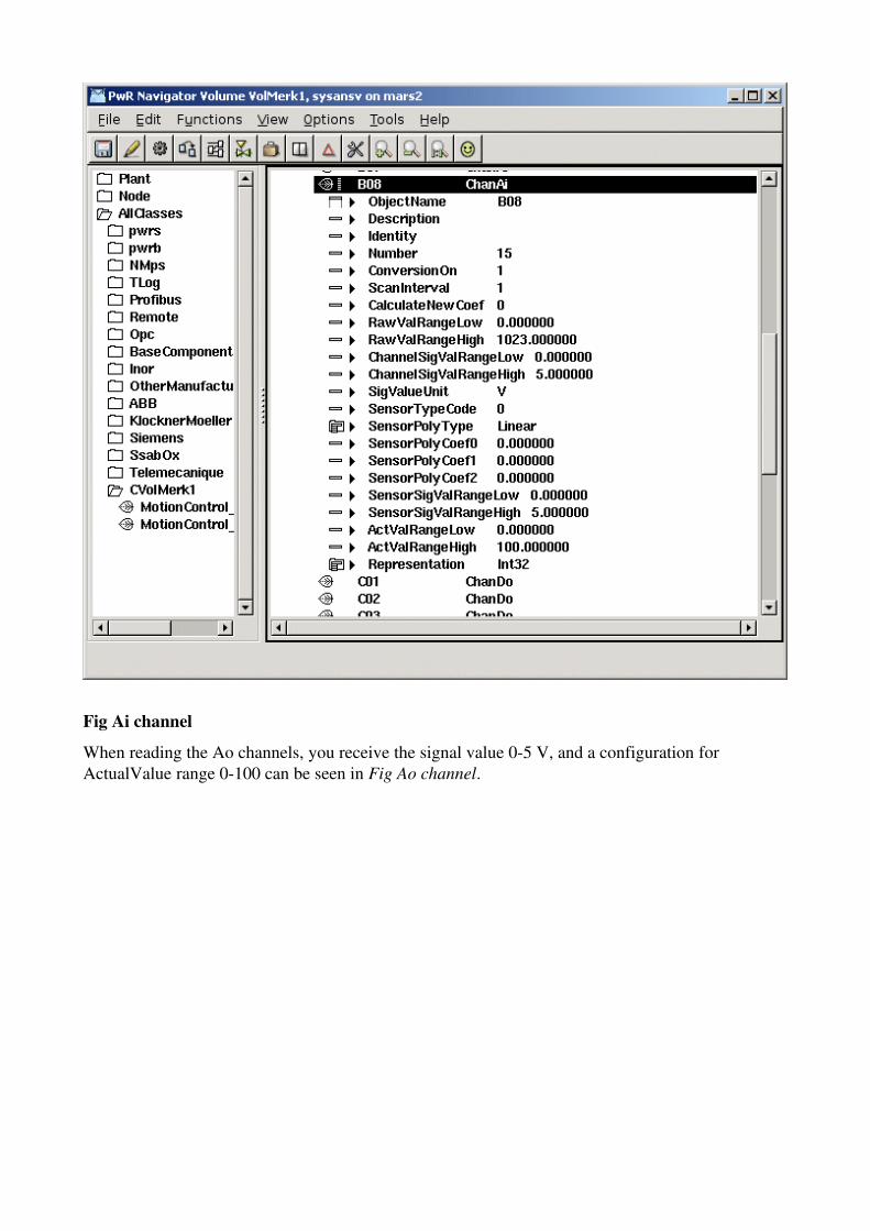
Fig Ai channel
When reading the Ao channels, you receive the signal value 05 V, and a configuration for ActualValue range 0100 can be seen in Fig Ao channel.
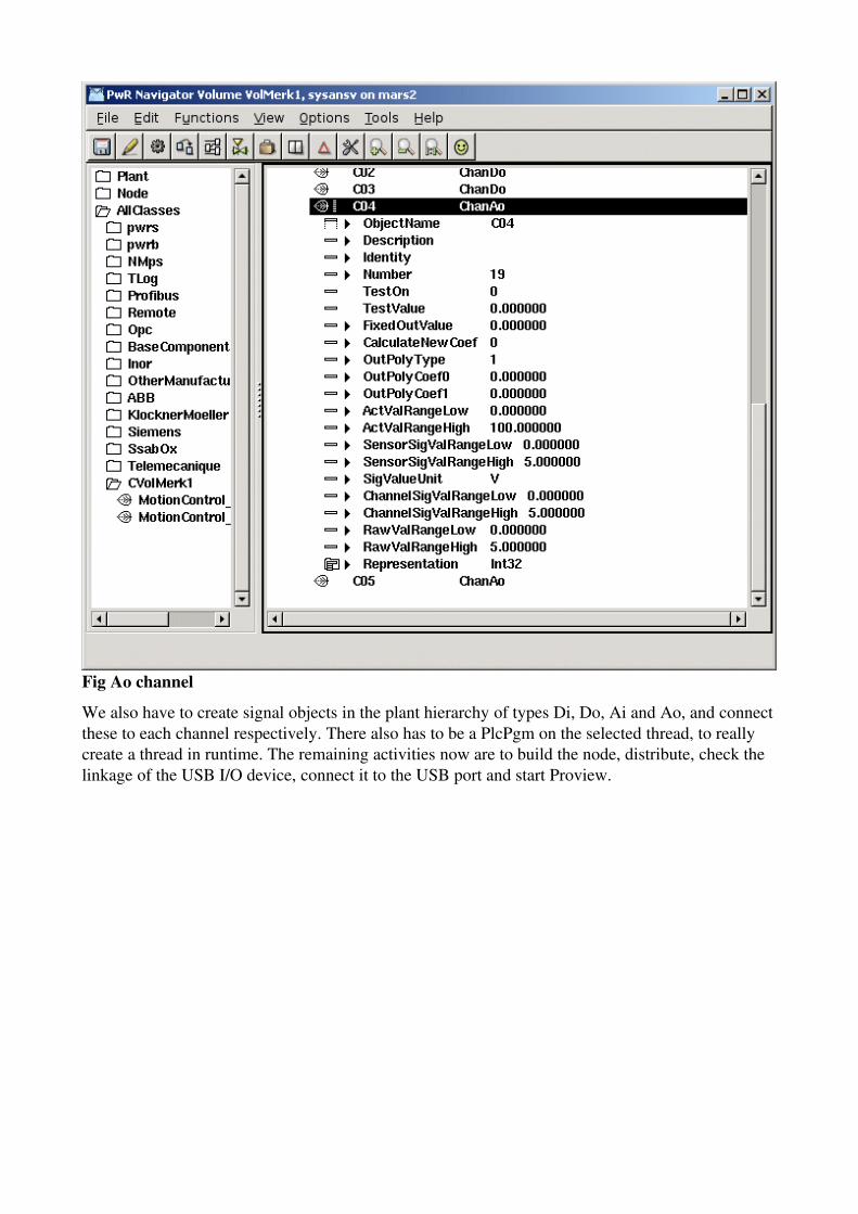
Fig Ao channel
We also have to create signal objects in the plant hierarchy of types Di, Do, Ai and Ao, and connect these to each channel respectively. There also has to be a PlcPgm on the selected thread, to really create a thread in runtime. The remaining activities now are to build the node, distribute, check the linkage of the USB I/O device, connect it to the USB port and start Proview.