Embed Size (px)
Citation preview
- 1 -Guide to Implementing PROFIBUS PA Field Devices
White Paper
White PaPer
Guide to Implementing PROFIBUS PA Field Devices
Executive Summary
PrOFiBUS Pa is the digital fieldbus technology with the highest distribution worldwide, which, in comparison to legacy analog communication, provides advantages for use in process automation applications and thus is supported in an increasing number of field devices. its functionality is defined by the PrOFiBUS standard and the PrOFiBUS Pa application profile.
this White Paper discusses the individual hardware and software aspects of implementing a PrOFiBUS Pa field device. While this implementation approach is applicable to a wide range of target platforms, it results in substantial development effort and a long implementation time if the implementation is performed by the manufacturer. it also requires in-depth fieldbus expertise. as a consequence, field device manufacturers are typically interested in reducing the associated expenses and in shortening the time-to-market. this goal can be reached by following implementation approaches based on using pre-engineered hardware and software components.
- i -Guide to Implementing PROFIBUS PA Field Devices
White Paper
Table of Contents
1. Introduction ............................................................................................................................... 1
2. PROFIBUS PA Overview ............................................................................................................. 3
3. Implementing a PROFIBUS PA Field Device ............................................................................. 7
3.1 PROFIBUS PA Hardware ......................................................................................................... 7
3.1.1 Medium Attachment Unit .................................................................................................8
3.1.2 Fieldbus Controller ............................................................................................................9
3.1.3 Processor..........................................................................................................................10
3.1.4 Additional Hardware Components ................................................................................ 11
3.2 PROFIBUS PA Protocol Stack and Function Block Application ......................................... 11
3.3 Transducer Block Implementation ..................................................................................... 13
3.3.1 Transducer Block Implementation Based on Serial HART Protocol ............................ 15
3.3.2 Transducer Block Implementation Based on Modbus RTU Protocol and Other Serial Protocols .....................................................................................................16
3.3.3 Transducer Block Implementation for 4..20mA Devices .............................................16
3.4 Add-On Files for PROFIBUS PA Field Devices ....................................................................16
3.5 Certification and Registration of PROFIBUS PA Field Devices ......................................... 17
4. Reducing the Implementation Effort of PROFIBUS PA Field Devices .................................18
4.1 PROFIBUS PA Fieldbus Device Communication Kit ...........................................................18
4.2 PROFIBUS PA Fieldbus Device Configuration Kit ..............................................................20
5. Summary ................................................................................................................................... 21
6. About Softing .......................................................................................................................... 24
7. Author ...................................................................................................................................... 24
8. References ...............................................................................................................................25
9. List of Figures ..........................................................................................................................25
10. List of Tables ............................................................................................................................25
- 1 -Guide to Implementing PROFIBUS PA Field Devices
White Paper
1. Introduction
in the past, process automation devices were based on proprietary or analog communication technology. For instance, the communication made use of 4..20ma1 or hart2 technology. Over the last couple of years, however, an increasing number of installations have been implemented based on digital fieldbuses, one of these being PrOFiBUS Pa.
the usage of digital fieldbus technology provides a set of functional benefits, including the high resolution measurement of values accompanied by no loss of accuracy and a highly reliable data transmission. it is based on standardized object models and access methods. the support of diagnostic and maintenance capabilities as well as asset monitoring and management functionality also contribute to the special advantages of digital fieldbuses.
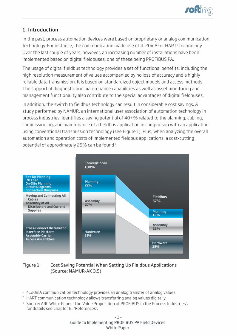
in addition, the switch to fieldbus technology can result in considerable cost savings. a study performed by NaMUr, an international user association of automation technology in process industries, identifies a saving potential of 40+% related to the planning, cabling, commissioning, and maintenance of a fieldbus application in comparison with an application using conventional transmission technology (see Figure 1). Plus, when analyzing the overall automation and operation costs of implemented fieldbus applications, a cost-cutting potential of approximately 25% can be found3.
Figure 1: Cost Saving Potential When Setting Up Fieldbus Applications(Source: NAMUR-AK 3.5)
1 4..20ma communication technology provides an analog transfer of analog values.2 hart communication technology allows transferring analog values digitally.3 Source: arC White Paper “the Value Proposition of PrOFiBUS in the Process industries”,
for details see Chapter 8, “references”.
Fieldbus 57%
Set-Up PlanningI/O LoadOn-Site PlanningCircuit DiagramsConnection Diagrams
Planning 12%
Moving and Connecting All Cables
Assembly of All Distributors and Current Supplies
Assembly 22%Cross-Connect Distributor
Interface PlatformAssembly CarrierAccess Assemblies
Hardware 23%
Conventional 100%
Planning 22%
Assembly 27%
Hardware 51%
- 2 -Guide to Implementing PROFIBUS PA Field Devices
White Paper
Due to the advantages of using digital fieldbuses, the number of implemented field devices is rapidly increasing. For instance, by the end of 2011 the PrOFiBUS & PrOFiNet international association reported more than 40 million sold PrOFiBUS devices, with about 7 million of these in process automation. thus, PrOFiBUS has to be seen as an important representative of fieldbus technology.
this increasing market potential leads to the decision of individual field device manufacturers to consider the implementation of a PrOFiBUS Pa field device as an important extension of their product portfolio. however, this plan may be jeopardized by the complex underlying technology4 that needs to be implemented for a PrOFiBUS Pa field device and which differs significantly from the communication technology that is used in legacy devices. as a consequence, the development of the fieldbus interface requires substantial expertise, which is often not available at the manufacturers. thus, there is big interest in options for implementing PrOFiBUS Pa field devices with manageable resources and impacts.
this situation is examined in detail by this White Paper, which is targeted to device manufacturers planning to introduce a PrOFiBUS Pa field device into the market. it gives an introduction into the PrOFiBUS Pa fieldbus technology and discusses hardware and software aspects of a PrOFiBUS Pa field device implementation. in addition, this White Paper also presents development approaches for PrOFiBUS Pa field devices, which have already proven to result in a shorter and more cost-efficient implementation of a PrOFiBUS Pa field device.
4 individual peer-to-peer connections are replaced by a deterministic fieldbus communication, supporting cyclic and acyclic data exchange and providing additional information.
- 3 -Guide to Implementing PROFIBUS PA Field Devices
White Paper
2. PROFIBUS PA Overview
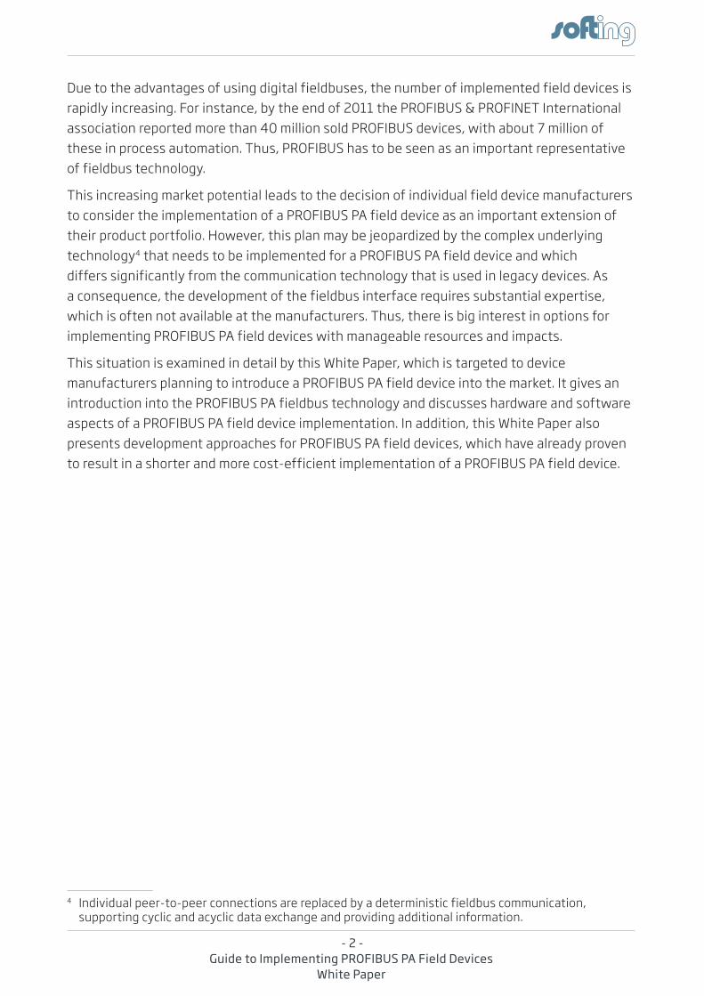
PrOFiBUS (PROcess FIeld BUS) is a world leading fieldbus communication standard in automation technology. it is designed for digital data exchange within a network using a single bus cable and achieves a high data transmission reliability. Based on different related application profiles, it provides solutions for a wide range of application areas including manufacturing and process automation (see Figure 2).
Figure 2: PROFIBUS PA as One of Various PROFIBUS Solutions Addressing Different Market Segments(Source: PROFIBUS & PROFINET International)
the history of PrOFiBUS goes back to 19875, when a publicly-funded collaborative project was launched by 18 companies and institutes in Germany, resulting in the specification of the PrOFiBUS Fieldbus Message Specification (FMS)6. in 1993, the PrOFiBUS Decentralized Peripherals (DP) standard was released, focusing on the simpler and much faster deterministic communication between PrOFiBUS masters and remote i/O field devices (sensors and actuators). PrOFiBUS DP implements the OSi layers 1 (Physical Layer), 2 (Data Link Layer), and 7 (application Layer).
Different versions of PrOFiBUS DP have been defined. PrOFiBUS DP-V0 provides the basic functionality of the communication protocol, addressing cyclic communication as well as device-specific, module-specific, and channel-specific diagnostics, in particular for quick fault localization7. the PrOFiBUS DP-V1 version supplements PrOFiBUS DP-V0 with
5 today, PrOFiBUS is standardized in ieC61158 type 3.6 this consortium commissioned Softing to develop the first PrOFiBUS FMS stack implementation,
which has been the starting point for Softing’s continuous commitment to the PrOFiBUS and fieldbus technology.
7 For instance, PrOFiBUS DP-V0 fault localization deals with faults like „excess temperature“ or „Short Circuit on Output“.
Market Segment
FactoryAutomation
MotionControl
SafetyApplication
PROFIBUS Solution(Common Term) PROFIBUS DP PROFIdrive Safety
Application Profiles
e.g.Ident Systems PROFIdrive PROFIsafe
CommunicationTechnology
PROFIBUS DP PROFIBUS DP PROFIBUS DP
TransmissionTechnology
RS485 RS485 RS485MBP-IS
Process AutomationEx / Non-Ex Areas
PROFIBUS PA
PA Devices (and Others)
PROFIBUS DP
MBP / MBP-ISRS485 / RS485-IS
- 4 -Guide to Implementing PROFIBUS PA Field Devices
White Paper
functionality for acyclic communication, i.e. supporting tasks such as parameterization, operation, monitoring, alarm handling, and maintenance. For this purpose, PrOFiBUS DP-V1 allows online access to bus nodes via engineering tools. in comparison to PrOFiBUS DP-V1, the PrOFiBUS DP-V2 version provides extended functionality, including time synchronization, isochronous real-time functionality as required for drive control as well as time-stamping and slave-to-slave communication.
the capabilities of individual PrOFiBUS field devices are described by the General Station Description (GSD) files, supplemented by the electronic Device Description (eDD) files. the GSD file contains the key data of an individual PrOFiBUS slave, information about its communication capabilities and, e.g. diagnostic values. it supplies all information necessary for the cyclic exchange of measured values and calculated variables between the field device and the PrOFiBUS master, and supports the configuration of the PrOFiBUS network. the eDD file provides additional information describing application-specific functions and the parameters of complex field devices. it comprises a description of acyclically communicated device capabilities, including graphics-based options, and device information such as order data, materials, maintenance instructions, etc.
in 1996, the PrOFiBUS Process automation (Pa) application profile was released. it uses the PrOFiBUS DP communication technology and especially addresses process automation needs. PrOFiBUS Pa is suitable for use in hazardous and potentially explosive areas (ex zones 0 and 1). in addition to supporting the standard PrOFiBUS DP transmission technology rS485, PrOFiBUS Pa can also perform the data transfer based on Manchester Coded Bus Powered (MBP)8, which is capable of supplying power to the individual field devices via the bus wire. as a consequence, the wiring overhead can be reduced significantly. MBP communication requires only 8Bits for encoding a character9. thus, PrOFiBUS Pa meets the requirements for a much simpler and safer installation and boasts all the benefits of digital transmission right down to the field device. PrOFiBUS Pa also supports intrinsically safe applications providing explosion protection by limiting the power supplied by the bus or the installation components in the field. it is widely used in chemical, oil, and gas industry applications.
the MBP transmission technology basically supports a variety of different topologies, including linear and simple tree structures. in practice, the „trunk & Spur topology“ (see Figure 3) has established itself as the de-facto standard, as it is particularly clear and well laid out. thanks to the technically mature installation technologies available on the market, it also exhibits a high degree of robustness. the overall length of a segment may not exceed 1,900m, and the length of the spurs in intrinsically safe applications is limited to 30m and must be taken into account when calculating the overall length.
8 the Manchester Coded Bus Powered transmission technology has been developed and standardized independently of the PrOFiBUS communication and addresses the demands of process automation. MBP is used by other fieldbuses as well, e.g. by FOUNDatiON fieldbus h1.
9 in comparison, standard PrOFiBUS DP uses the serial Uart NrZ (Non-return-to-Zero) communication, which is based on 11Bit character encoding.
- 5 -Guide to Implementing PROFIBUS PA Field Devices
White Paper
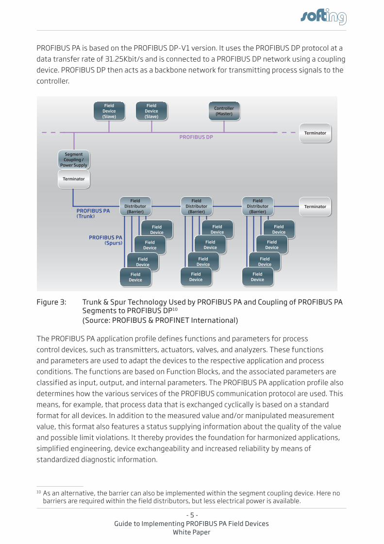
PrOFiBUS Pa is based on the PrOFiBUS DP-V1 version. it uses the PrOFiBUS DP protocol at a data transfer rate of 31.25Kbit/s and is connected to a PrOFiBUS DP network using a coupling device. PrOFiBUS DP then acts as a backbone network for transmitting process signals to the controller.
Figure 3: Trunk & Spur Technology Used by PROFIBUS PA and Coupling of PROFIBUS PA Segments to PROFIBUS DP10
(Source: PROFIBUS & PROFINET International)
the PrOFiBUS Pa application profile defines functions and parameters for process control devices, such as transmitters, actuators, valves, and analyzers. these functions and parameters are used to adapt the devices to the respective application and process conditions. the functions are based on Function Blocks, and the associated parameters are classified as input, output, and internal parameters. the PrOFiBUS Pa application profile also determines how the various services of the PrOFiBUS communication protocol are used. this means, for example, that process data that is exchanged cyclically is based on a standard format for all devices. in addition to the measured value and/or manipulated measurement value, this format also features a status supplying information about the quality of the value and possible limit violations. it thereby provides the foundation for harmonized applications, simplified engineering, device exchangeability and increased reliability by means of standardized diagnostic information.
10 as an alternative, the barrier can also be implemented within the segment coupling device. here no barriers are required within the field distributors, but less electrical power is available.
profiBUS Dp
profiBUS pA (Trunk)
Controller (Master)
field Device (Slave)
field Device (Slave)
Segment Coupling /
power Supply
Terminator
Terminator
Terminator
field Device
field Device
field Device
field Device
field Distributor
(Barrier)
field Device
field Device
field Device
field Device
field Device
field Device
field Device
field Device
field Distributor
(Barrier)
field Distributor
(Barrier)
profiBUS pA (Spurs)

- 6 -Guide to Implementing PROFIBUS PA Field Devices
White Paper
the latest version V3.02 of the PrOFiBUS Pa application profile especially addresses user requests for comprehensive diagnostic and status information as well as the requirements of system-oriented asset management for field devices within process automation applications.
- 7 -Guide to Implementing PROFIBUS PA Field Devices
White Paper
3. Implementing a PROFIBUS PA Field Device
the implementation of a PrOFiBUS Pa field device has to follow the PrOFiBUS standard and the PrOFiBUS Pa application profile specification. thus an implementation has to be focused on a set of individual areas, including the communication hardware as well as software components like the protocol stack and the transducer Block. the individual implementation aspects regarding a PrOFiBUS Pa field device implementation are discussed in detail in the following sections.
3.1 PROFIBUS PA Hardware
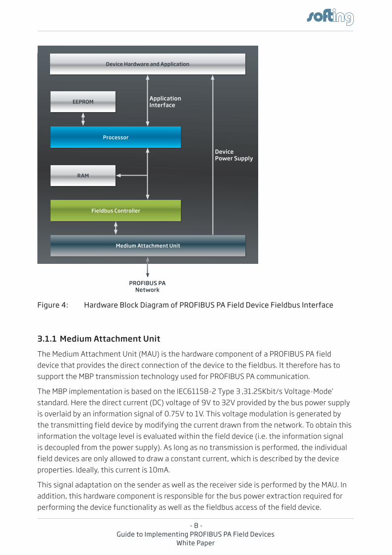
the hardware of a PrOFiBUS Pa field device has to support a Physical Layer as required for MBP communication. this results in a more complex hardware structure than that of a standard PrOFiBUS DP device using an rS485 interface. as a consequence, a PrOFiBUS Pa field device comprises different hardware components which are required for connecting a device to the PrOFiBUS Pa network, for performing low-level operations within the PrOFiBUS communication, and for executing the PrOFiBUS Pa stack plus the associated Function Block application. an overview about of the overall hardware structure of a PrOFiBUS Pa fieldbus interface is given in Figure 4.
- 8 -Guide to Implementing PROFIBUS PA Field Devices
White Paper
Figure 4: Hardware Block Diagram of PROFIBUS PA Field Device Fieldbus Interface
3.1.1 Medium Attachment Unit
the Medium attachment Unit (MaU) is the hardware component of a PrOFiBUS Pa field device that provides the direct connection of the device to the fieldbus. it therefore has to support the MBP transmission technology used for PrOFiBUS Pa communication.
the MBP implementation is based on the ieC61158-2 type 3 ‚31.25Kbit/s Voltage-Mode‘ standard. here the direct current (DC) voltage of 9V to 32V provided by the bus power supply is overlaid by an information signal of 0.75V to 1V. this voltage modulation is generated by the transmitting field device by modifying the current drawn from the network. to obtain this information the voltage level is evaluated within the field device (i.e. the information signal is decoupled from the power supply). as long as no transmission is performed, the individual field devices are only allowed to draw a constant current, which is described by the device properties. ideally, this current is 10ma.
this signal adaptation on the sender as well as the receiver side is performed by the MaU. in addition, this hardware component is responsible for the bus power extraction required for performing the device functionality as well as the fieldbus access of the field device.
Device Power Supply
Processor
RAM
Fieldbus Controller
Medium Attachment Unit
EEPROM
Device Hardware and Application
Application Interface
PROFIBUS PA Network
- 9 -Guide to Implementing PROFIBUS PA Field Devices
White Paper
there are different ways to implement the analog Medium attachment Unit within a PrOFiBUS Pa field device. While it is possible to set up this functionality based on discrete hardware components, this option is often not used due to the limited space available in field devices. an integrated MaU11 is chosen instead in order to implement the core fieldbus access functionality within a PrOFiBUS Pa field device. integrated MaUs are available from various suppliers (e.g. SiM 1-2 from Siemens, aMiS-492x0 from ON Semiconductor).
3.1.2 Fieldbus Controller
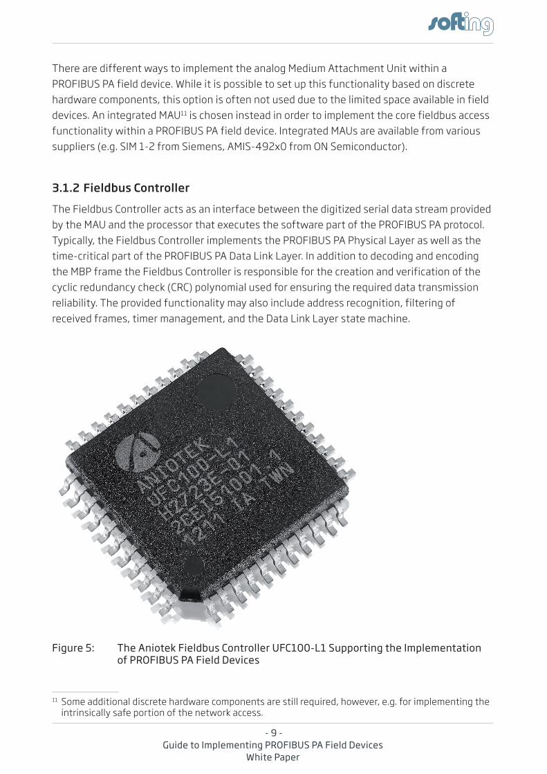
the Fieldbus Controller acts as an interface between the digitized serial data stream provided by the MaU and the processor that executes the software part of the PrOFiBUS Pa protocol. typically, the Fieldbus Controller implements the PrOFiBUS Pa Physical Layer as well as the time-critical part of the PrOFiBUS Pa Data Link Layer. in addition to decoding and encoding the MBP frame the Fieldbus Controller is responsible for the creation and verification of the cyclic redundancy check (CrC) polynomial used for ensuring the required data transmission reliability. the provided functionality may also include address recognition, filtering of received frames, timer management, and the Data Link Layer state machine.
Figure 5: The Aniotek Fieldbus Controller UFC100-L1 Supporting the Implementation of PROFIBUS PA Field Devices
11 Some additional discrete hardware components are still required, however, e.g. for implementing the intrinsically safe portion of the network access.
- 10 -Guide to Implementing PROFIBUS PA Field Devices
White Paper
there are two different types of Fieldbus Controllers available for implementing a PrOFiBUS Pa field device: While one type is particularly targeted for use in a PrOFiBUS Pa field device (e.g. SPC4-212 from Siemens), other Fieldbus Controllers also support a parallel implementation of FOUNDatiON™ fieldbus h1 field devices (e.g. UFC100-L1 from aniotek, YtZ420 from Yamaha)13.
3.1.3 Processor
the processor is used for executing the software part of the PrOFiBUS Pa protocol stack (i.e. the less time-critical part, which is not covered by the Fieldbus Controller). here processors for embedded usage are required, which combine minimum current consumption with the appropriate computing power for implementing PrOFiBUS Pa field devices.
as PrOFiBUS Pa is a relatively complex protocol, its implementation requires an address space >64KB. While this requirement can also be supported by an 8Bit processor, the usage of this platform results in a higher clock rate, which in turn implies a higher current consumption and is thus not adequate for embedded applications. therefore, 16Bit or even 32Bit processors are typically chosen for the implementation of PrOFiBUS Pa field devices.
as a PrOFiBUS Pa field device implementation requires not only computing power, but also additional hardware capacities like raM and Flash memory, timers, ports and serial interfaces, the hardware implementation often is based on a microcontroller, a typcial example being the M16C family from renesas.
Besides the PrOFiBUS Pa protocol stack, a PrOFiBUS Pa field device also includes additional software for the device application. Depending on the selected hardware platform, it is possible to either execute all software components on a single processor, which results in a higher processor load, or to distribute the execution of the complete device software to more than one processor (e.g. dual-processor solution)14. in the second case, more effort has to be spent on implementing the necessary data exchange between the individual processors.
12 the SPC4-2 Fieldbus Controller also allows the implementation of a FOUNDatiON fieldbus h1 field device but involves a higher implementation effort.
13 the PrOFiBUS Pa and FOUNDatiON fieldbus h1 fieldbuses both use the same Physical Layer based on Manchester Coded Bus Powered communication according to the ieC61158-2 type 1/type 3 ‚31.25Kbit/s Voltage-Mode‘ standard, whereas the Data Link Layers of both protocols differ. as a consequence, it is possible to support both fieldbuses on a single field device hardware platform, including the Fieldbus Controller. Only the software part of the implementation has to be adapted to the concept and functionality of the individual fieldbus.
14 While a single-processor solution typically means the usage of only one hardware board, the implementation of a PrOFiBUS Pa field device based on multiple processors may result in a combination of several hardware boards (e.g., one hardware board executing the device application plus a piggy-back hardware board executing the PrOFiBUS Pa protocol stack).
- 11 -Guide to Implementing PROFIBUS PA Field Devices
White Paper
3.1.4 Additional Hardware Components
Besides the hardware components described above additional hardware components are required for implementing a PrOFiBUS Pa field device. these hardware components may include additional raM memory extending the processor’s internal raM or a (serial) eePrOM or FraM, which is used for storing non-volatile communication and Function Block parameters.
hardware jumpers are often used in addition. they provide functionality like address selection or write protection.
3.2 PROFIBUS PA Protocol Stack and Function Block Application
as described above, the PrOFiBUS Pa protocol makes use of the OSi layers 1 (Physical Layer), 2 (Data Link Layer), and 7 (application Layer). While the Physical Layer as well as parts of the Data Link Layer are implemented in hardware (see Sections 3.1.1 and 3.1.2), the rest of the PrOFiBUS Pa protocol stack is implemented in software. to ensure optimum performance, the protocol stack needs to be available in a format executable on the individual target processor. this format is the result of the porting process, during which the protocol stack is compiled and linked for the target hardware platform and real-time operating system by using a specific development tool chain15.
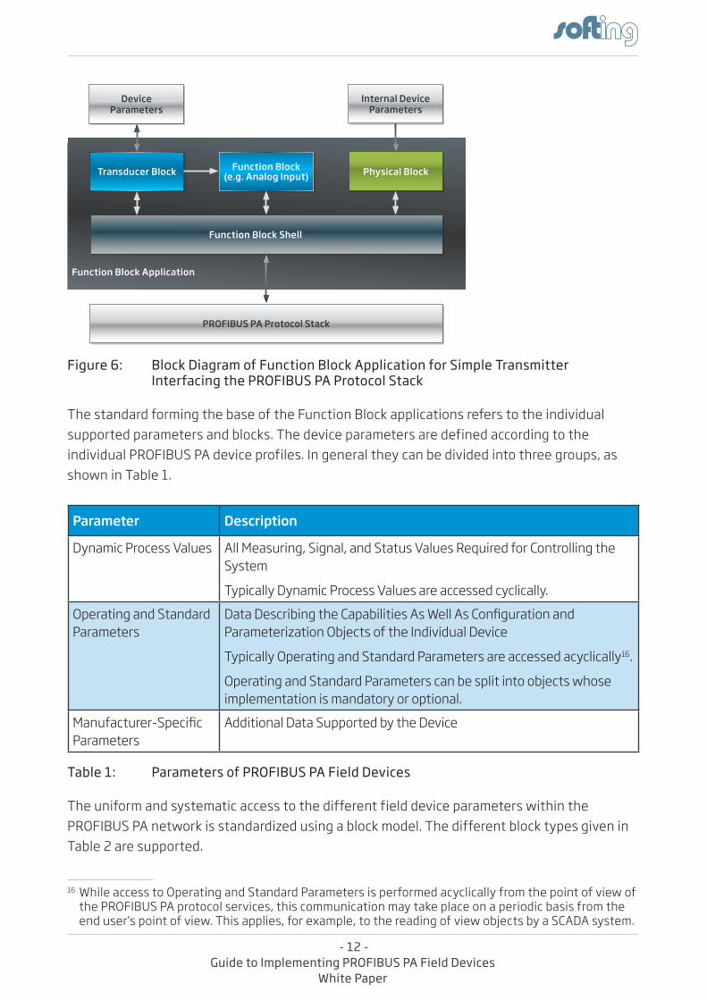
in addition to the protocol stack, which is responsible for the pure data exchange via the fieldbus, the PrOFiBUS Pa field device implementation also requires a Function Block application. this component acts as an interface between the PrOFiBUS Pa protocol stack on one side and the specific device functionality on the other side and ensures that all device functions and parameters as well as access to this data are standardized throughout the network. to achieve this, the Function Block application follows an object-oriented approach and allows implementing all the different types of PrOFiBUS Pa field devices. the block diagram of a Function Block application for implementing a simple PrOFiBUS Pa transmitter is shown in Figure 6.
15 a PrOFiBUS Pa implementation does not necessarily require the use of an operating system. however, this communication protocol deals with different tasks, which are more or less time-critical and thus are associated with various priorities (e.g. data exchange with the application, data exchange with the fieldbus). Without the assistance of an operating system, this type of functionality would have to be implemented in another way, maybe resulting in a long and confusing code. thus, the use of a real-time operating system is recommended when implementing a PrOFiBUS Pa field device.
- 12 -Guide to Implementing PROFIBUS PA Field Devices
White Paper
Figure 6: Block Diagram of Function Block Application for Simple Transmitter Interfacing the PROFIBUS PA Protocol Stack
the standard forming the base of the Function Block applications refers to the individual supported parameters and blocks. the device parameters are defined according to the individual PrOFiBUS Pa device profiles. in general they can be divided into three groups, as shown in table 1.16
Parameter Description
Dynamic Process Values all Measuring, Signal, and Status Values required for Controlling the System
typically Dynamic Process Values are accessed cyclically.
Operating and Standard Parameters
Data Describing the Capabilities As Well As Configuration and Parameterization Objects of the individual Device
typically Operating and Standard Parameters are accessed acyclically16.
Operating and Standard Parameters can be split into objects whose implementation is mandatory or optional.
Manufacturer-Specific Parameters
additional Data Supported by the Device
Table 1: Parameters of PROFIBUS PA Field Devices
the uniform and systematic access to the different field device parameters within the PrOFiBUS Pa network is standardized using a block model. the different block types given in table 2 are supported.
16 While access to Operating and Standard Parameters is performed acyclically from the point of view of the PrOFiBUS Pa protocol services, this communication may take place on a periodic basis from the end user‘s point of view. this applies, for example, to the reading of view objects by a SCaDa system.
Transducer Block
Device Parameters
Physical Block
Function Block Shell
Internal Device Parameters
PROFIBUS PA Protocol Stack
Function Block (e.g. Analog Input)
Function Block Application
- 13 -Guide to Implementing PROFIBUS PA Field Devices
White Paper
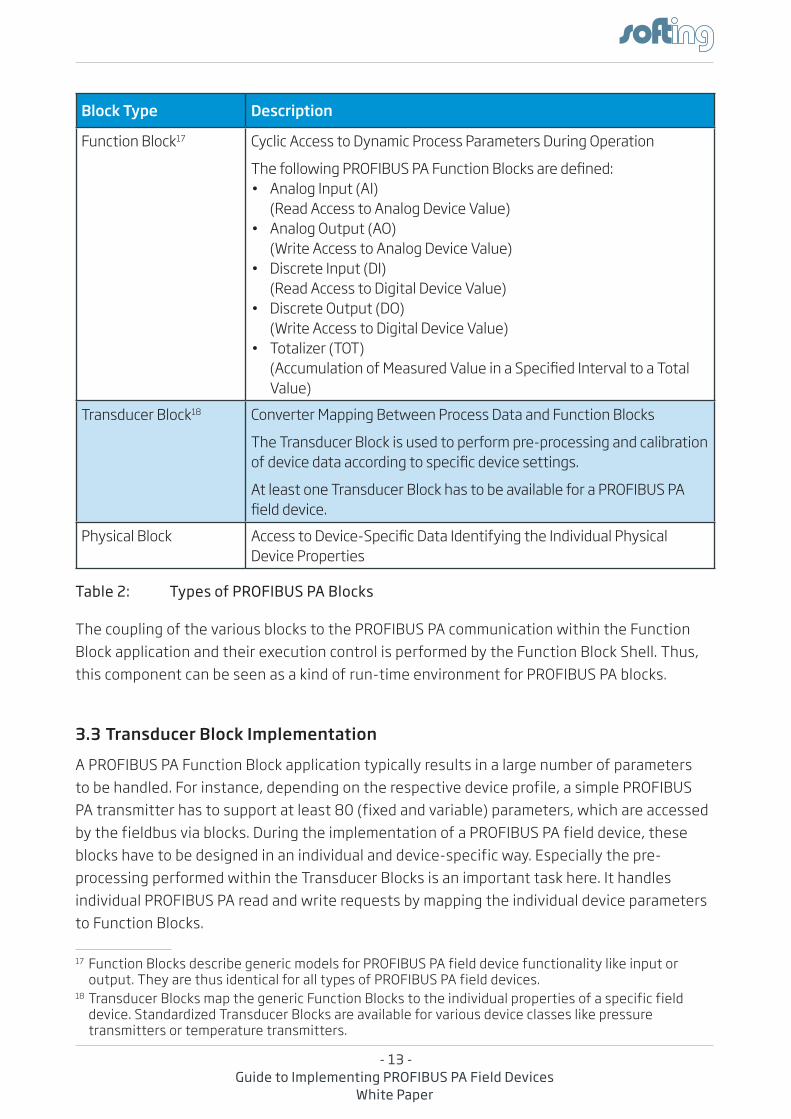
Block Type Description
Function Block17 Cyclic access to Dynamic Process Parameters During Operation
The following PROFIBUS PA Function Blocks are defined:• Analog Input (AI)
(read access to analog Device Value)• Analog Output (AO)
(Write access to analog Device Value)• Discrete Input (DI)
(read access to Digital Device Value)• Discrete Output (DO)
(Write access to Digital Device Value)• Totalizer (TOT)
(Accumulation of Measured Value in a Specified Interval to a Total Value)
transducer Block18 Converter Mapping Between Process Data and Function Blocks
the transducer Block is used to perform pre-processing and calibration of device data according to specific device settings.
at least one transducer Block has to be available for a PrOFiBUS Pa field device.
Physical Block Access to Device-Specific Data Identifying the Individual Physical Device Properties
Table 2: Types of PROFIBUS PA Blocks1718
the coupling of the various blocks to the PrOFiBUS Pa communication within the Function Block application and their execution control is performed by the Function Block Shell. thus, this component can be seen as a kind of run-time environment for PrOFiBUS Pa blocks.
3.3 Transducer Block Implementation
a PrOFiBUS Pa Function Block application typically results in a large number of parameters to be handled. For instance, depending on the respective device profile, a simple PrOFiBUS Pa transmitter has to support at least 80 (fixed and variable) parameters, which are accessed by the fieldbus via blocks. During the implementation of a PrOFiBUS Pa field device, these blocks have to be designed in an individual and device-specific way. especially the pre-processing performed within the transducer Blocks is an important task here. it handles individual PrOFiBUS Pa read and write requests by mapping the individual device parameters to Function Blocks.
17 Function Blocks describe generic models for PrOFiBUS Pa field device functionality like input or output. they are thus identical for all types of PrOFiBUS Pa field devices.
18 transducer Blocks map the generic Function Blocks to the individual properties of a specific field device. Standardized transducer Blocks are available for various device classes like pressure transmitters or temperature transmitters.
- 14 -Guide to Implementing PROFIBUS PA Field Devices
White Paper
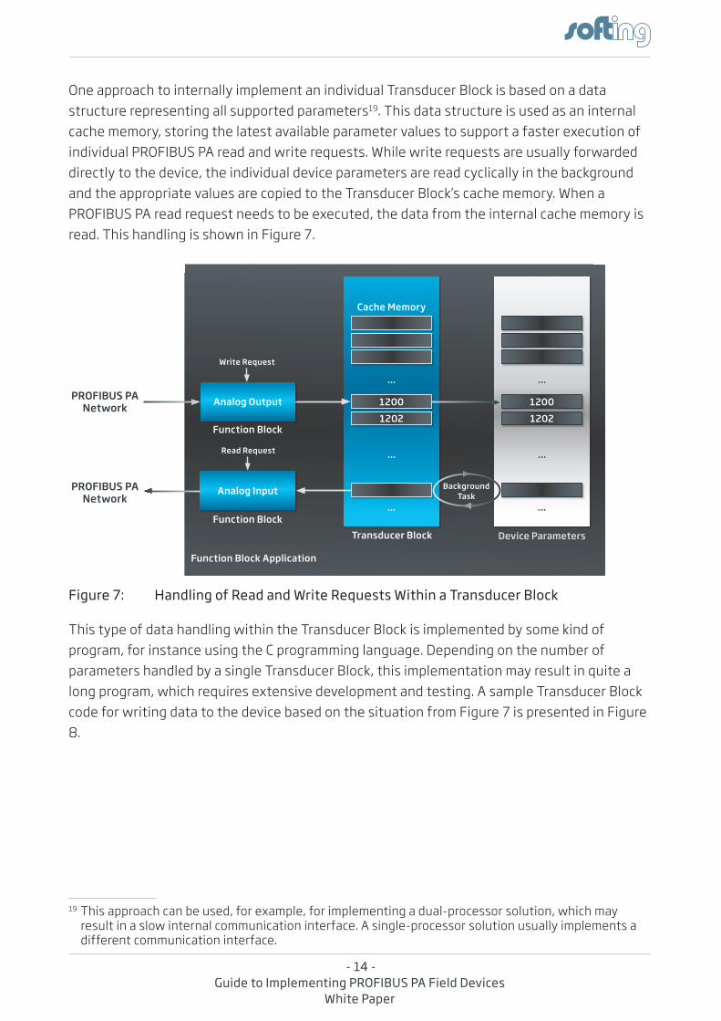
One approach to internally implement an individual transducer Block is based on a data structure representing all supported parameters19. this data structure is used as an internal cache memory, storing the latest available parameter values to support a faster execution of individual PrOFiBUS Pa read and write requests. While write requests are usually forwarded directly to the device, the individual device parameters are read cyclically in the background and the appropriate values are copied to the transducer Block’s cache memory. When a PrOFiBUS Pa read request needs to be executed, the data from the internal cache memory is read. this handling is shown in Figure 7.
Figure 7: Handling of Read and Write Requests Within a Transducer Block
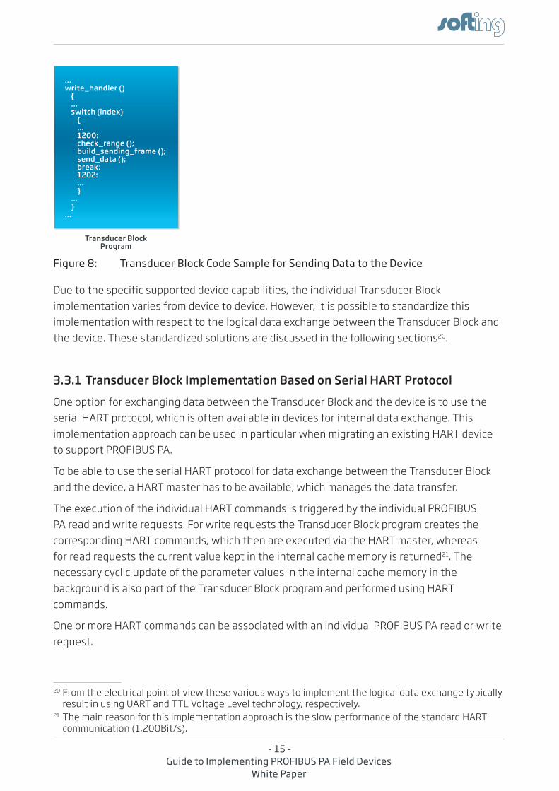
this type of data handling within the transducer Block is implemented by some kind of program, for instance using the C programming language. Depending on the number of parameters handled by a single transducer Block, this implementation may result in quite a long program, which requires extensive development and testing. a sample transducer Block code for writing data to the device based on the situation from Figure 7 is presented in Figure 8.
19 this approach can be used, for example, for implementing a dual-processor solution, which may result in a slow internal communication interface. a single-processor solution usually implements a different communication interface.
Device ParametersTransducer Block
Analog Input
Function Block Application
Function Block
Function Block
Cache Memory
1200
1202
...
...
...
Write Request
Read Request
Analog OutputPROFIBUS PA Network
PROFIBUS PA Network
1200
1202
...
...
...
Background Task
- 15 -Guide to Implementing PROFIBUS PA Field Devices
White Paper
Figure 8: Transducer Block Code Sample for Sending Data to the Device
Due to the specific supported device capabilities, the individual transducer Block implementation varies from device to device. however, it is possible to standardize this implementation with respect to the logical data exchange between the transducer Block and the device. these standardized solutions are discussed in the following sections20.
3.3.1 Transducer Block Implementation Based on Serial HART Protocol
One option for exchanging data between the transducer Block and the device is to use the serial hart protocol, which is often available in devices for internal data exchange. this implementation approach can be used in particular when migrating an existing hart device to support PrOFiBUS Pa.
to be able to use the serial hart protocol for data exchange between the transducer Block and the device, a hart master has to be available, which manages the data transfer.
the execution of the individual hart commands is triggered by the individual PrOFiBUS Pa read and write requests. For write requests the transducer Block program creates the corresponding hart commands, which then are executed via the hart master, whereas for read requests the current value kept in the internal cache memory is returned21. the necessary cyclic update of the parameter values in the internal cache memory in the background is also part of the transducer Block program and performed using hart commands.
One or more hart commands can be associated with an individual PrOFiBUS Pa read or write request.
20 From the electrical point of view these various ways to implement the logical data exchange typically result in using Uart and ttL Voltage Level technology, respectively.
21 the main reason for this implementation approach is the slow performance of the standard hart communication (1,200Bit/s).
Transducer Block Program
Function Block Application
…write_handler () { … switch (index) { … 1200: check_range (); build_sending_frame (); send_data (); break; 1202: … } … }…
- 16 -Guide to Implementing PROFIBUS PA Field Devices
White Paper
3.3.2 Transducer Block Implementation Based on Modbus RTU Protocol and Other Serial Protocols
another typical approach for implementing a PrOFiBUS Pa field device is the usage of the serial Modbus rtU protocol for data exchange between the transducer Block and the device. this approach is similar to the data exchange via a serial hart protocol as discussed in Section 3.3.1, only that here the data exchange is managed by a Modbus rtU master.
this procedure can also be easily adapted to allow the use of other serial protocols for data exchange between the transducer Block and the device, including proprietary ones. the implementation of data exchange via non-serial protocols is more complicated, however, as these require their own hardware.
3.3.3 Transducer Block Implementation for 4..20mA Devices
For migrating 4..20ma devices to PrOFiBUS Pa no standard approach is available. the reason is the current required by these devices: a 20ma current consumption at a voltage of 8V would result in a current consumption of about 60ma to 70ma from the PrOFiBUS Pa network22. this would mean that only one to two PrOFiBUS Pa field devices could be used within an intrinsically safe trunk, which typically disqualifies the device for practical use.
in addition, a special Medium attachment Unit would be required in order to support the increased current consumption, resulting in higher hardware costs.
3.4 Add-On Files for PROFIBUS PA Field Devices
For using a PrOFiBUS Pa field device, the GSD and eDD files are additionally available in order to describe its capabilities. an overview of these files can be found in Chapter 2.
the GSD file of a PrOFiBUS Pa field device is required for its registration, while the support of the eDD file is optional. the capabilities of the eDD file also can be provided by other means, e.g. by using a Device type Manager (DtM) file according to the Field Device tool (FDt) standard.
22 according to the specification 4..20ma devices work with a voltage of 8V to 10V. thus the given current consumption from the PrOFiUS Pa network already applies to 4..20ma devices working with a voltage at the lower end of this range.
- 17 -Guide to Implementing PROFIBUS PA Field Devices
White Paper
3.5 Certification and Registration of PROFIBUS PA Field Devices
the PrOFiBUS Pa certification process comprises two individual tests. One test is the Physical Layer test23, during which the device is checked against the appropriate Physical Layer requirements of the PrOFiBUS & PrOFiNet international organization. the Physical Layer test is performed by an accredited testing laboratory as part of the certification test.
in addition to the Physical Layer test, the successful pass of the PrOFiBUS Pa test24 is also required for the certification of a PrOFiBUS Pa field device. this test also has to be performed by an accredited testing laboratory. During the PrOFiBUS Pa test, the behavior of a complete PrOFiBUS Pa device together with its GSD file is tested, combining the PrOFiBUS Pa field device implementation with the device implementation. as a result, this test ensures the supported high quality of the individual PrOFiBUS Pa field device implementation, its full functionality as well as the interoperability, easy installation, and supported performance of the field device.
Once a PrOFiBUS Pa field device has passed the required certification tests, it can be registered at the PrOFiBUS & PrOFiNet international organization. For this registration process the appropriate GSD file (see Section 3.4) also has to be provided.
23 Softing has the PrOFiBUS Pa Physical Layer test at its disposal and thus supports the performance of an individual pre-certification test prior to the official certification test. as a consequence, any related issues can probably be solved at an early stage.
24 Softing has the PrOFiBUS Pa test at its disposal and thus supports the performance of an individual pre-certification test prior to the official certification test. as a consequence, any related issues can probably be solved at an early stage.
- 18 -Guide to Implementing PROFIBUS PA Field Devices
White Paper
4. Reducing the Implementation Effort of PROFIBUS PA Field Devices
as can be seen from the description in Chapter 3 the complete implementation of a full-featured PrOFiBUS Pa field device with all its individual capabilities is quite an extensive task and addresses various hardware and software aspects. thus, many device manufacturers are interested in identifying the best ways to reduce the implementation effort of PrOFiBUS Pa field devices without compromising on the requested flexibility. here implementation kits based on pre-engineered hardware and software components can help to significantly reduce the associated development costs as well as the time-to-market.
4.1 PROFIBUS PA Fieldbus Device Communication Kit
the PrOFiBUS Pa Fieldbus Device Communication Kit25 makes use of pre-engineered, standardized hardware and software components and thus provides a universal approach for implementing all types of PrOFiBUS Pa field devices.
the PrOFiBUS Pa Fieldbus Device Communication Kit includes a hardware board, which meets the various requirements discussed in Section 3.1 and thus eliminates the need for customer-specific hardware development. this board is integrated into a device as an add-on piggy-back board and provides all the means for executing the PrOFiBUS Pa protocol stack plus the appropriate Function Block application. in addition, it is also capable of supplying power from the fieldbus to the field device hardware.
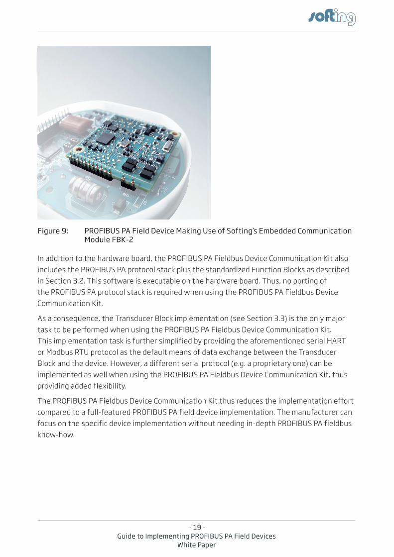
the device implementation, on the other hand, runs on the device’s main board. as a result, a dual-processor solution is implemented, separating the PrOFiBUS Pa implementation from the pure device functionality. the Softing embedded communication module FBK-2 as part of a PrOFiBUS Pa field device implementation is shown in Figure 9. as can be seen, this board is small enough to fit into most devices.
25 the PrOFiBUS Pa Fieldbus Device Communication Kit is a product offered by Softing.
- 19 -Guide to Implementing PROFIBUS PA Field Devices
White Paper
Figure 9: PROFIBUS PA Field Device Making Use of Softing’s Embedded Communication Module FBK-2
in addition to the hardware board, the PrOFiBUS Pa Fieldbus Device Communication Kit also includes the PrOFiBUS Pa protocol stack plus the standardized Function Blocks as described in Section 3.2. this software is executable on the hardware board. thus, no porting of the PrOFiBUS Pa protocol stack is required when using the PrOFiBUS Pa Fieldbus Device Communication Kit.
as a consequence, the transducer Block implementation (see Section 3.3) is the only major task to be performed when using the PrOFiBUS Pa Fieldbus Device Communication Kit. this implementation task is further simplified by providing the aforementioned serial hart or Modbus rtU protocol as the default means of data exchange between the transducer Block and the device. however, a different serial protocol (e.g. a proprietary one) can be implemented as well when using the PrOFiBUS Pa Fieldbus Device Communication Kit, thus providing added flexibility.
the PrOFiBUS Pa Fieldbus Device Communication Kit thus reduces the implementation effort compared to a full-featured PrOFiBUS Pa field device implementation. the manufacturer can focus on the specific device implementation without needing in-depth PrOFiBUS Pa fieldbus know-how.
- 20 -Guide to Implementing PROFIBUS PA Field Devices
White Paper
4.2 PROFIBUS PA Fieldbus Device Configuration Kit
in comparison to the PrOFiBUS Pa Fieldbus Device Communication Kit, the PrOFiBUS Pa Fieldbus Device Configuration Kit26 simplifies the implementation of a PrOFiBUS Pa field device even more. to achieve this, a standardized Function Block application including a pre-defined transducer Block implementation is added to the PrOFiBUS Pa Fieldbus Device Communication Kit. this Function Block application can be adapted to the needs of the individual field device.
For supporting this type of standardization, some assumptions regarding the field device have to be made. For instance, these standardizations restrict the available Function Blocks27 and the supported number of flexible parameters28.
these standardizations have the advantage that the complete development process of a PrOFiBUS Pa field device requires no programming, but can be performed simply by configuring the Function Block application. this task requires no specific PrOFiBUS Pa know-how and can be done by any device manufacturer. as a result, the development time is shortened significantly.
the scope of delivery of the PrOFiBUS Pa Fieldbus Device Configuration Kit also includes the appropriate GSD file required for certification.
26 the PrOFiBUS Pa Fieldbus Device Configuration Kit is a product offered by Softing.27 the Softing PrOFiBUS Pa Fieldbus Device Configuration Kit supports up to four instances of the
analog input Function Block. thus the use case of the PrOFiBUS Pa Fieldbus Device Configuration Kit is limited to field devices of transmitter type.
28 the Softing PrOFiBUS Pa Fieldbus Device Configuration Kit supports up to 25 flexible parameters.
- 21 -Guide to Implementing PROFIBUS PA Field Devices
White Paper
5. Summary
the implementation of a PrOFiBUS Pa field device must meet a variety of hardware and software requirements defined by the PrOFiBUS standard and the PrOFiBUS Pa application profile. Depending on the required functionality and the available fieldbus know-how, this implementation may involve a great deal of development time and effort when performed without pre-engineered fieldbus communication components.
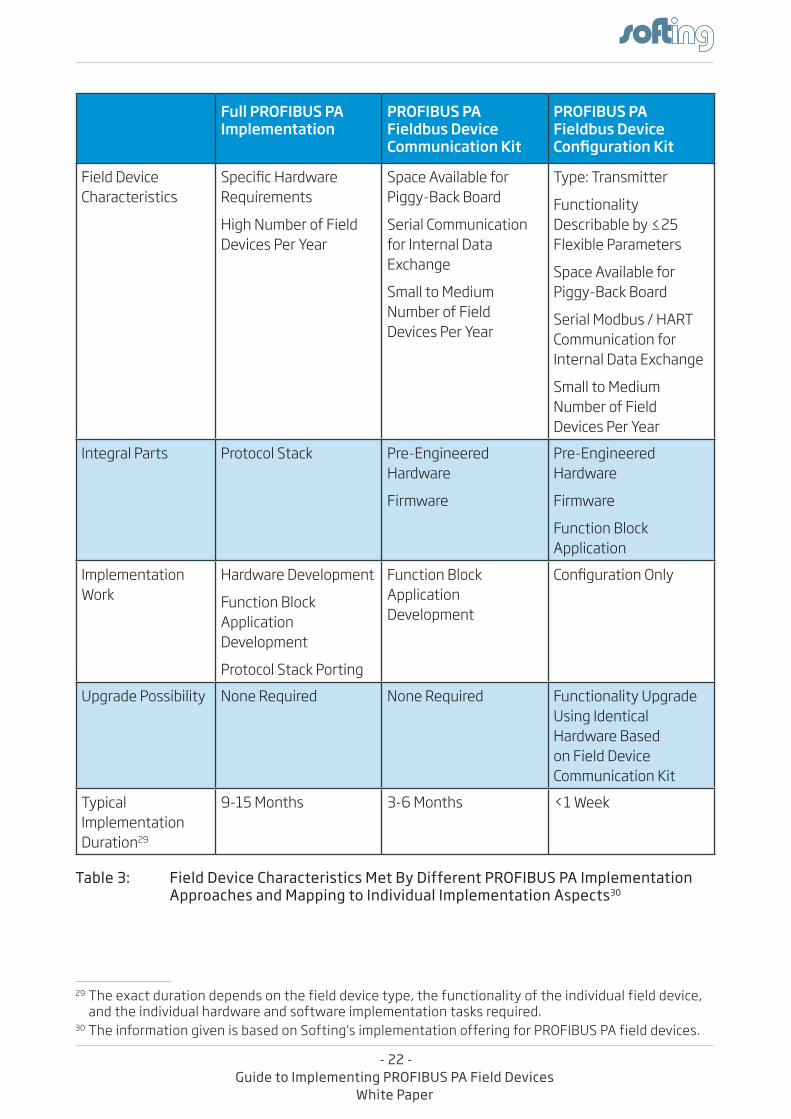
a field device implementation based on the PrOFiBUS Pa Fieldbus Device Communication Kit or better still the PrOFiBUS Pa Fieldbus Device Configuration Kit significantly reduces the involved time and effort. these approaches, however, are associated with some drawbacks, e.g. regarding the hardware used and the supported functionality. a summary of the provided field device characteristics plus individual aspects of the different implementation approaches discussed in this White Paper can be found in table 3.
- 22 -Guide to Implementing PROFIBUS PA Field Devices
White Paper
29
Full PROFIBUS PA Implementation
PROFIBUS PA Fieldbus Device Communication Kit
PROFIBUS PA Fieldbus Device Configuration Kit
Field Device Characteristics
Specific Hardware requirements
high Number of Field Devices Per Year
Space available for Piggy-Back Board
Serial Communication for internal Data exchange
Small to Medium Number of Field Devices Per Year
type: transmitter
Functionality Describable by ≤25 Flexible Parameters
Space available for Piggy-Back Board
Serial Modbus / hart Communication for internal Data exchange
Small to Medium Number of Field Devices Per Year
integral Parts Protocol Stack Pre-engineered hardware
Firmware
Pre-engineered hardware
Firmware
Function Block application
implementation Work
hardware Development
Function Block application Development
Protocol Stack Porting
Function Block application Development
Configuration Only
Upgrade Possibility None required None required Functionality Upgrade Using identical hardware Based on Field Device Communication Kit
typical implementation Duration29
9-15 Months 3-6 Months <1 Week
Table 3: Field Device Characteristics Met By Different PROFIBUS PA Implementation Approaches and Mapping to Individual Implementation Aspects30
29 the exact duration depends on the field device type, the functionality of the individual field device, and the individual hardware and software implementation tasks required.
30 the information given is based on Softing‘s implementation offering for PrOFiBUS Pa field devices.
- 23 -Guide to Implementing PROFIBUS PA Field Devices
White Paper
Besides PrOFiBUS Pa, FOUNDatiON fieldbus h1 is another fieldbus standard used in process automation. While this fieldbus differs from PrOFiBUS Pa in both concept and functionality, it is based on the same Physical Layer defined in the ieC61158-2 standard. thus, once a PrOFiBUS Pa field device has been implemented, a major step towards a parallel implementation of this fieldbus has already been made. a key aspect here is that the implementation of a FOUNDatiON fieldbus h1 field device does not require different hardware.
in addition the software development effort can be reduced as well if both implementations are based on the Softing Field Device stack. For instance this solution provides an identical interface and allows the re-use of parts of the transducer Block structures and the source code. the implemented data exchange between the transducer Block and the device can also be re-used. the exact percentage of savings that can be achieved in a subsequent FOUNDatiON fieldbus h1 implementation cannot be given as a general figure, however, as it depends on the complexity of the PrOFiBUS Pa field device implemented in the first place.
- 24 -Guide to Implementing PROFIBUS PA Field Devices
White Paper
6. About Softing
the Softing industrial automation segment is part of the Softing group founded in 1979.
Softing industrial automation is a global specialist in industrial communication technologies such as fieldbuses and industrial ethernet. With over 30 years of experience, Softing delivers connectivity, diagnostic products, and services to customers in the factory and process automation industry, serving the market from different subsidiaries.
the Softing products are tailored to the needs of system integrators, device vendors, machine and equipment manufacturers, or end users and are known for their ease of use and functional advantages. implementation projects have been successfully performed with many international customers from various countries, including europe, U.S.a., Japan, China, and Korea. Softing‘s relationship with its customers is shaped by a high degree of flexibility for meeting individual requirements as well as by a long-term partnership.
Softing has been involved in the PrOFiBUS technology since the very beginning of the PrOFiBUS project in 1987. today, the Softing PrOFiBUS offering is proven-in-use in a wide variety of applications of a large number of manufacturers and end-users around the world.
Softing offers a complete set of options for implementing PrOFiBUS Pa field devices. these options combine high-quality products and professional services, available from a single source. Customers benefit from the provided in-depth technical experience and the quality resulting from field-proven products.
Softing industrial automation Gmbh richard-reitzner-allee 6 De-85540 haar Germany Phone: +49 / (0)89 / 45656-340 Fax: +49 / (0)89 / 45656-488 email: [email protected] http://industrial.softing.com
7. Author
Georg Süss Operational Marketing Softing industrial automation Gmbh haar (near Munich), Germany
- 25 -Guide to Implementing PROFIBUS PA Field Devices
White Paper
8. References
• PrOFiBUS System Description, technology and application Order No. 4.332 PrOFiBUS Nutzerorganisation e.V., November 2010
• http://www.profibus.com/technology/profibus/overview/
• the Value Proposition of PrOFiBUS in the Process industries arC White Paper arC advisory Group, april 2005
• Why use PrOFiBUS for Process automation? Siemens Milltronics Process instruments inc., 2005
9. List of Figures
10. List of Tables
Figure 1: Cost Saving Potential When Setting Up Fieldbus applications ................................... 1
Figure 2: PrOFiBUS Pa as One of Various PrOFiBUS Solutions addressing Different Market Segments ....................................................................................................3
Figure 3: trunk & Spur technology Used by PrOFiBUS Pa and Coupling of PrOFiBUS Pa Segments to PrOFiBUS DP ..........................................................................5
Figure 4: hardware Block Diagram of PrOFiBUS Pa Field Device Fieldbus interface ............ 8
Figure 5: the aniotek Fieldbus Controller UFC100-L1 Supporting the implementation of PrOFiBUS Pa Field Devices ............................................................... 9
Figure 6: Block Diagram of Function Block application for Simple transmitter interfacing the PrOFiBUS Pa Protocol Stack ................................................................. 12
Figure 7: handling of read and Write requests Within a transducer Block .......................... 14
Figure 8: transducer Block Code Sample for Sending Data to the Device............................... 15
Figure 9: PrOFiBUS Pa Field Device Making Use of Softing’s embedded Communication Module FBK-2 ............................................................................................ 19
table 1: Parameters of PrOFiBUS Pa Field Devices ........................................................................... 12
table 2: types of PrOFiBUS Pa Blocks ................................................................................................... 13
table 3: Field Device Characteristics Met By Different PrOFiBUS Pa implementation approaches and Mapping to individual implementation aspects . 22