Embed Size (px)
Citation preview
GUIDE TO CONVENTION FOR SAFE CONTAINERS (CSC) REINSPECTION OF MODULAR CAUSEWAY SYSTEMS (MCS) ISOPAK
COMPONENTS
Prepared by:
Randy Cassner (586) 574-6998
Product Quality Manager RDECOM
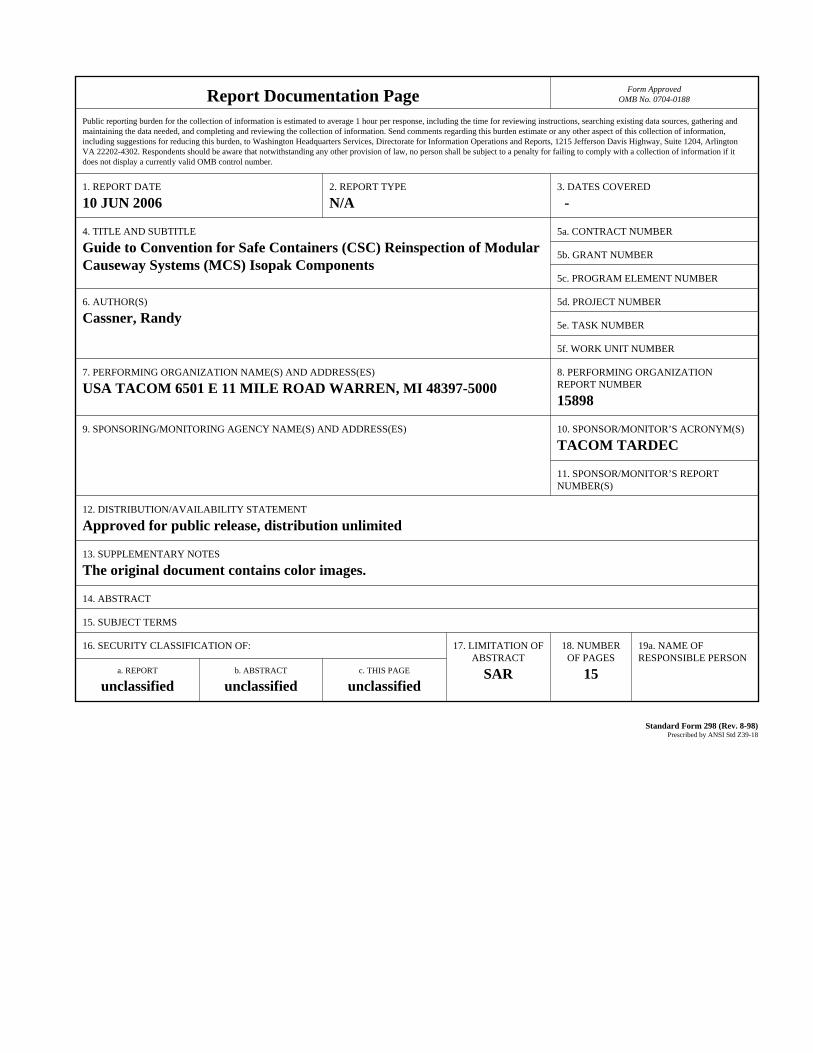
Report Documentation Page Form ApprovedOMB No. 0704-0188
Public reporting burden for the collection of information is estimated to average 1 hour per response, including the time for reviewing instructions, searching existing data sources, gathering andmaintaining the data needed, and completing and reviewing the collection of information. Send comments regarding this burden estimate or any other aspect of this collection of information,including suggestions for reducing this burden, to Washington Headquarters Services, Directorate for Information Operations and Reports, 1215 Jefferson Davis Highway, Suite 1204, ArlingtonVA 22202-4302. Respondents should be aware that notwithstanding any other provision of law, no person shall be subject to a penalty for failing to comply with a collection of information if itdoes not display a currently valid OMB control number.
1. REPORT DATE 10 JUN 2006
2. REPORT TYPE N/A
3. DATES COVERED -
4. TITLE AND SUBTITLE Guide to Convention for Safe Containers (CSC) Reinspection of ModularCauseway Systems (MCS) Isopak Components
5a. CONTRACT NUMBER
5b. GRANT NUMBER
5c. PROGRAM ELEMENT NUMBER
6. AUTHOR(S) Cassner, Randy
5d. PROJECT NUMBER
5e. TASK NUMBER
5f. WORK UNIT NUMBER
7. PERFORMING ORGANIZATION NAME(S) AND ADDRESS(ES) USA TACOM 6501 E 11 MILE ROAD WARREN, MI 48397-5000
8. PERFORMING ORGANIZATIONREPORT NUMBER 15898
9. SPONSORING/MONITORING AGENCY NAME(S) AND ADDRESS(ES) 10. SPONSOR/MONITOR’S ACRONYM(S) TACOM TARDEC
11. SPONSOR/MONITOR’S REPORT NUMBER(S)
12. DISTRIBUTION/AVAILABILITY STATEMENT Approved for public release, distribution unlimited
13. SUPPLEMENTARY NOTES The original document contains color images.
14. ABSTRACT
15. SUBJECT TERMS
16. SECURITY CLASSIFICATION OF: 17. LIMITATION OF ABSTRACT
SAR
18. NUMBEROF PAGES
15
19a. NAME OFRESPONSIBLE PERSON
a. REPORT unclassified
b. ABSTRACT unclassified
c. THIS PAGE unclassified
Standard Form 298 (Rev. 8-98) Prescribed by ANSI Std Z39-18
Army Modular Causeway Systems ISOPAK Components CSC Reinspection Process
FOREWORD
In accordance with AR 56-4 paragraph 3.3, intermodal configured modular systems must meet regulatory requirements to include CSC certification. In conformance with 49 CFR 452, in order to maintain CSC certification and ensure continued safe handling and transportability in the commercial intermodal transport environment, the intermodal configured modules must be periodically examined. In accordance with DOD 4500.9-R DEFENSE TRANSPORTATION REGULATION PART VI, All ISO containers (ISOPAK’s are classified as ISO containers for purposes of intermodal movement) that move in the Defense Transportation System (DTS) must be certified to meet 49 CFR and CSC/46 U.S.C. app. 1503 standards. This Modular Causeway Systems (MCS) reinspection program endeavors to comply with these directives and ensure that no injury to personnel or damage to property occurs from structural failure or deficiency. This document provides reinspection criteria and procedures to be used when visually examining MCS ISOPAK components. The criteria and procedures contained herein enable personnel to identify MCS components that are serviceable and safe for intermodal loading and shipping. This document applies to any commercially owned or military owned Modular Causeway Component System meeting the standards of the International Organization for Standardization (ISO) and certified under the provisions of the International Convention for Safe Containers (CSC). This document is specifically used worldwide by civilians and military personnel responsible for inspecting and selecting serviceable MCS Components for shipment of Department of Defense (DOD) materiel. This document provides a variety of helpful illustrations. Beneficial comments (recommendations, additions, deletions), and any other pertinent data that may be of use in improving this document, should be addressed to: Commander, U.S. Tank Automotive Armaments Command; ATTN: Program Executive Office Combat Support and Combat Service Support (PEO CS& CSS), Warren Michigan 48397-5000; or by letter.
1. GENERAL 1.1 Purpose This document provides inspection criteria and procedures will be used when visually examining MCS Components. Following the criteria and procedures contained herein will enable personnel to identify MCS Components that are serviceable and safe for loading and shipping. MCS is constructed of many different components, the inspection of each component is to recertify that they may be used in an ISOPAK or identify the component as unserviceable.
NOTE: This document is not to be used as the standard for performing container repairs. 1.2 Scope This document applies to the selection of any commercially owned or military owned MCS components meeting the standards of the International Organization for Standardization (ISO), and certified under the provisions of the International Convention for Safe Containers (CSC). This document is specifically used worldwide by civilians and military personnel responsible for inspecting and selecting serviceable MCS components for shipment of Department of Defense (DOD) materiel. 1.3 Objective Inspecting personnel will use this document to cause: a. Inspection standardization among DOD agencies for acceptability of MCS modules owned by the DOD. b. Preparation of inspection reports that are properly annotated to reflect MCS component condition and reason(s) for rejection; and c. Compliance with international treaties, conventions, and United States transportation law.
2. CONTAINER INSPECTION CRITERIA 2.1 General Requirements 2.1.1 Regulatory Mandates: An MCS ISOPAK may not be offered for the carriage of any type unless the container is structurally serviceable as evidenced by a valid CSC Safety Approval Plate and verified by a detailed visual examination. The CSC Safety Approval Plate and the visual examination must conform to the mandates of 49 CFR, parts 451 and 452. Furthermore, if the MCS has any Hazardous Material, it must meet specific structural serviceability requirements as prescribed by the IMDG Code and mandated by 49 CFR Part 176.172. If an MCS has any safety related deficiency or damage that could place any person in danger, it will not be used. 2.1.2 Markings and Data Plates: Each MCS module must bear a legible and valid CSC Safety Approval Plate marked in accordance with CSC format requirements. The CSC Safety Approval Plate will be securely affixed at a readily visible place on the MCS, where it is not easily damaged. All maximum gross weight markings on the manufacturer’s data plate must be consistent with the maximum gross weight marking on the CSC Safety Approval Plate. No ISO PAK is constrained by specific serial numbers; each component/module is a stand-alone unit that may be configured into an ISO PAK. An ISO PAK is defined as a group of components, when assembled, meets the ISO dimensional requirements for an intermodal container. 2.1.3 Configuration: Any distortion of the overall configuration great enough to preclude proper engagement of handling/lifting equipment, mounting and securing on chassis, vehicle, or aircraft pallet, or insertion into the cell of a ship is unacceptable. Side-to-side connector castings may not protrude beyond the ISO envelope by not more than 3/8. The external dimensions must conform to the tolerances prescribed by ISO standard 668 as depicted in Figure 2 .1.
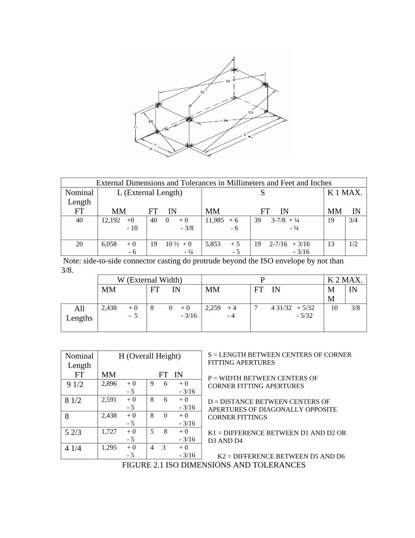
External Dimensions and Tolerances in Millimeters and Feet and Inches Nominal Length
FT
L (External Length) MM FT IN
S
MM FT IN
K 1 MAX.
MM IN 40 12,192 +0
- 10 40 0 + 0 - 3/8
11,985 + 6 - 6
39 3-7/8 + ¼ - ¼
19 3/4
20 6,058 + 0 - 6
19 10 ½ + 0 - ¼
5,853 + 5 - 5
19 2-7/16 + 3/16 - 3/16
13 1/2
Note: side-to-side connector casting do protrude beyond the ISO envelope by not than 3/8.
W (External Width) P K 2 MAX.MM FT IN MM FT IN M
M IN
All Lengths
2,438 + 0 - 5
8 0 + 0 - 3/16
2,259 + 4 - 4
7 4 31/32 + 5/32 - 5/32
10 3/8
S = LENGTH BETWEEN CENTERS OF CORNER FITTING APERTURES P = WIDTH BETWEEN CENTERS OF CORNER FITTING APERTURES D = DISTANCE BETWEEN CENTERS OF APERTURES OF DIAGONALLY OPPOSITE CORNER FITTINGS K1 = DIFFERENCE BETWEEN D1 AND D2 OR D3 AND D4
K2 = DIFFERENCE BETWEEN D5 AND D6 FIGURE 2.1 ISO DIMENSIONS AND TOLERANCES
Nominal Length
FT
H (Overall Height)
MM FT IN 9 1/2 2,896 + 0
- 5 9 6 + 0 - 3/16
8 1/2 2,591 + 0 - 5
8 6 + 0 - 3/16
8 2,438 + 0 - 5
8 0 + 0 - 3/16
5 2/3 1,727 + 0 - 5
5 8 + 0 - 3/16
4 1/4 1,295 + 0 - 5
4 3 + 0 - 3/16
2.2 Primary Structural Components: An MCS with any major defect in any component of its primary structure is unacceptable. For purposes of this criterion, primary (main) structural components (members) include: corner fittings, corner posts, top, bottom, and sides. 2.2.1 Acceptable Welding Patterns: MCS are originally deemed suitable for use if they have been given CSC certification by such agencies as the United States Coast Guard (USCG) or USCG appointed agencies. These agencies are highly reputable and bear the liability that the MCS is manufactured in accordance with ISO and CSC requirements. Welding patterns conforming to the original manufacturer’s design are, therefore, acceptable. Since welding patterns may vary depending on design and manufacture, inspection should be directed at looking for broken junctures or welded repairs that are not consistent with other corresponding welds of that container. 2.2.2 Acceptable Repairs: For purposes of these criteria, a repair is any repair of a primary structural member that replaces material without complete replacement of the member. Areas repaired by straightening and/or bead welding are not to be construed as splices. Gussets, backup plates or other reinforcement (protector) plates are not to be construed as repairs. An acceptable repair on steel side, bottom, or top is butt-welded, flush fitting and restores the original size and cross-sectional profile of the repaired component. An acceptable repair is a minimum of 6 inches (150mm) long. Both inserts and section (full profile) are acceptable types of repair, but not in all cases. Read inspection criteria of the component for specific repair allowances and IAW applicable repair manuals. If a repair would end within 12 inches (300mm) of another weld, such as at the juncture with the corner fitting, it must be extended to that weld. Backup plates installed on the backside of a splice are permissible if the backup plate extends a minimum of 6 inches (150mm) beyond each end of the repair. 2.2.3 Major Defects:
a. General MCS A major defect includes:
1) A crack, break, cut, tear, puncture, or corrosive failure in any primary structural component;
2) A missing, cracked, or broken corner fittings; 3) A missing, cracked, or broken weld at the juncture between any primary
structural components; 4) Any outward deformation such as a dent, bend or bow in any primary
structural component that is in excess of ISO external dimensional tolerances as depicted in Figure 2.1;
5) An improper splice (e.g. less than 6 inches long) in any primary
structural component;
6) Any damage to, or degradation within, a structural component which could place any person in danger during subsequent handling, stacking, or transport of the MCS.
b. Hazardous Material: For a powered module which contains any hazardous
material, a major defect includes any of the defects listed above, or a dent or bend in any primary structural component that is greater than 3/4 inch (19mm) in depth, regardless of length.
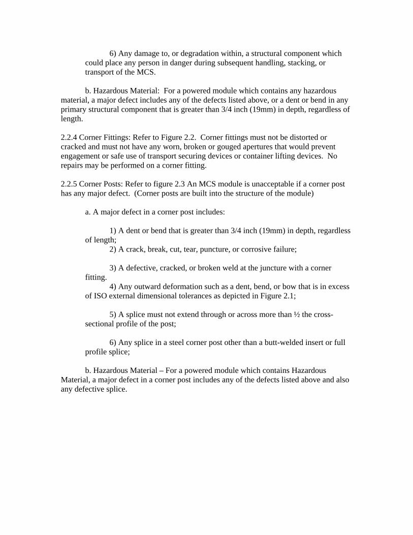
2.2.4 Corner Fittings: Refer to Figure 2.2. Corner fittings must not be distorted or cracked and must not have any worn, broken or gouged apertures that would prevent engagement or safe use of transport securing devices or container lifting devices. No repairs may be performed on a corner fitting. 2.2.5 Corner Posts: Refer to figure 2.3 An MCS module is unacceptable if a corner post has any major defect. (Corner posts are built into the structure of the module)
a. A major defect in a corner post includes:
1) A dent or bend that is greater than 3/4 inch (19mm) in depth, regardless of length;
2) A crack, break, cut, tear, puncture, or corrosive failure; 3) A defective, cracked, or broken weld at the juncture with a corner
fitting. 4) Any outward deformation such as a dent, bend, or bow that is in excess
of ISO external dimensional tolerances as depicted in Figure 2.1; 5) A splice must not extend through or across more than ½ the cross-
sectional profile of the post; 6) Any splice in a steel corner post other than a butt-welded insert or full
profile splice; b. Hazardous Material – For a powered module which contains Hazardous
Material, a major defect in a corner post includes any of the defects listed above and also any defective splice.
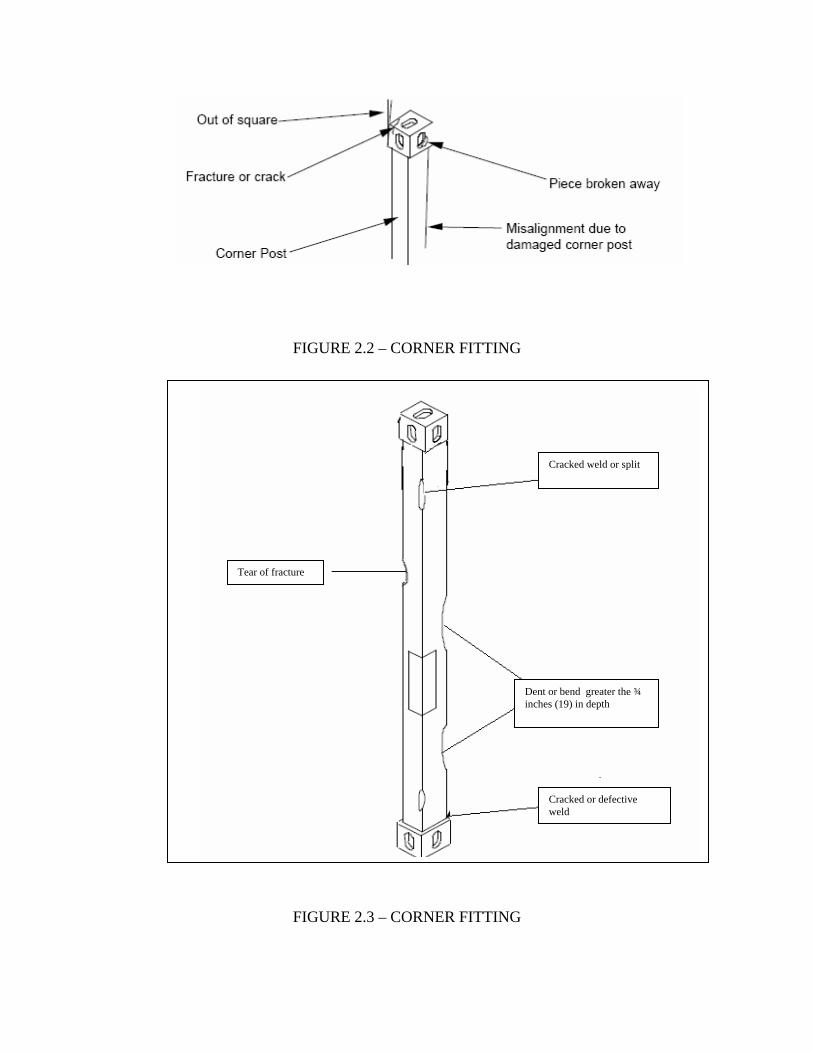
FIGURE 2.2 – CORNER FITTING
Cracked or defective weld
Dent or bend greater the ¾ inches (19) in depth
Tear of fracture
Cracked weld or split
FIGURE 2.3 – CORNER FITTING
2.2.6 Top, Bottom, End (wall) plating, or Sides (TBS). An MCS module is unacceptable if a Top, Bottom, or Side wall has any major defect.
a. Major defects include:
1) A dent or bend in the TBS that is greater than 1-9/16 inch in depth, regardless of length;
2) A crack, break, cut, tear, puncture, or corrosive failure in the TBS;
3) A missing, cracked, or broken weld at the juncture between primary
structural components;
4) Any outward deformation such as a dent, bend or bow in any primary structural component that is in excess of ISO external dimensional tolerances as depicted in Figure 2.1;
b. For a powered module which contains Hazardous Material a major defect
includes any of the defects listed above as well as a dent or bend in a top, bottom, or side that is greater than 3/4 inch (19mm) in depth, regardless of length.
3. CONTAINER INSPECTION PROCEDURES 3.1 Prerequisites: 3.1.1 Inspector Qualifications:
a. The CSC re-inspection must be performed by qualified personnel, trained and experienced in the detection of container structural damage. 3.1.2 Judgment of Criteria: The MCS inspection criteria will be met through a visual examination and, except where tolerances are provided, acceptance of the MCS will be based on the judgment of the inspector. 3.2 Suggested Tools and Equipment: 3.2.1 Long Straight Edge: A tautly drawn wire, string, or other form of a long straight edge is needed to determine whether any portion of the MCS (e.g., a side or a top) protrudes past the outside surfaces of the corner fittings. 3.2.2 Measuring Tape (Ruler): A measuring tape (ruler) is required to check dimensional tolerances and MCS alignment. 3.2.3 Welder's Hammer: A welder's hammer is helpful in determining the strength of welds or steel structural components
3.2.4 Ladder: A ladder or other safe means for accessing the top of the MCS is recommended.
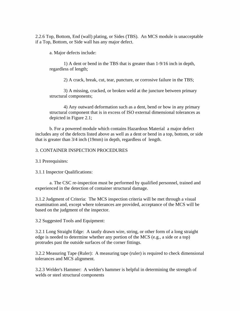
3.2.5 Flashlight: A flashlight improves visual acuity, especially during examination of the interior or the recesses of the understructure. 3.2.6 Chalk: Marking (circling) location of defects with chalk as they are discovered facilitates preparation of inspection report and helps maintenance personnel locate areas to be repaired. 3.2.7 Depth Gauge: A device with a straight edge and a point enables inspector to check depth of dents against a designated limit. 3.4 Documents: 3.4.1 Modular Causeway CSC Inspection Checklist: An MCS inspection checklist must be used to ensure complete examination and to indicate acceptance or reason(s) for failure. Appendix A contains the CSC checklist for MCS described in this document. A separate checklist shall be completed for each MCS module. All deficiencies found during inspection should be clearly annotated on the checklist and acceptance or rejection must be indicated, sign and dated. After a CSC reinspection is performed by a qualified inspector and the MCS is found acceptable, the owner will apply/stamp a new date of inspection or a new CSC Safety Approval Plate.
Figure 2.4 Typical Consolidated Data Plate.
MODULAR CAUSEWAY CSC INSPECTION CHECKLIST Appendix A MCS Serial Number Date of Inspection
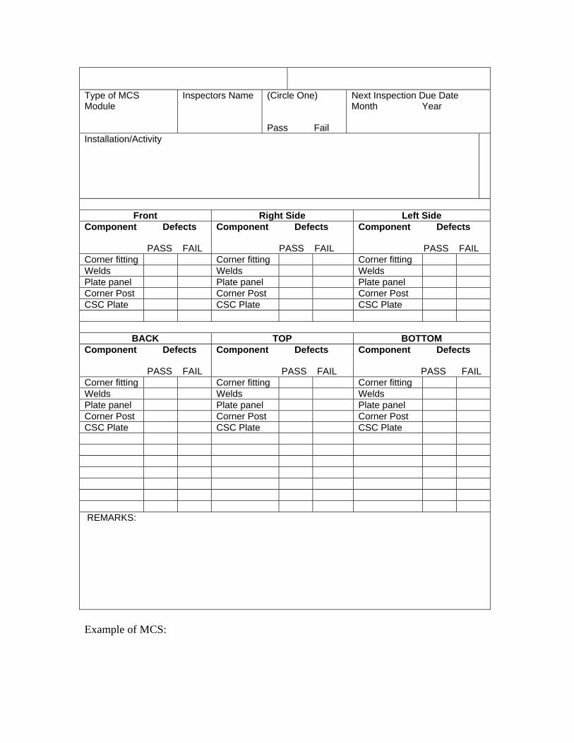
Type of MCS Module
Inspectors Name (Circle One) Pass Fail
Next Inspection Due Date Month Year
Installation/Activity
Front Right Side Left Side
Component Defects PASS FAIL
Component Defects PASS FAIL
Component Defects PASS FAIL
Corner fitting Corner fitting Corner fitting Welds Welds Welds Plate panel Plate panel Plate panel Corner Post Corner Post Corner Post CSC Plate CSC Plate CSC Plate
BACK TOP BOTTOM
Component Defects PASS FAIL
Component Defects PASS FAIL
Component Defects PASS FAIL
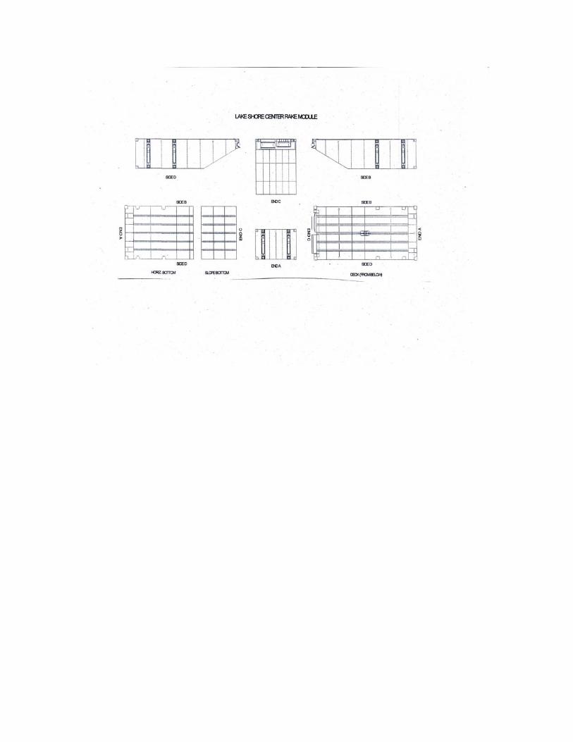
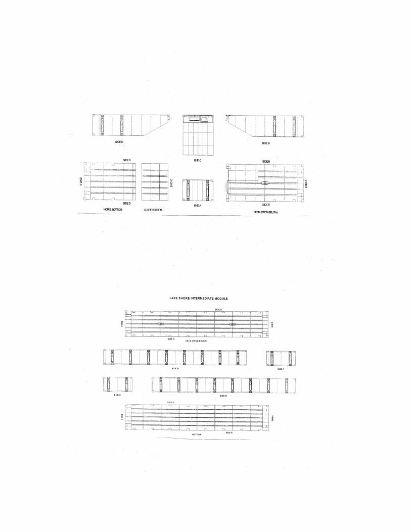
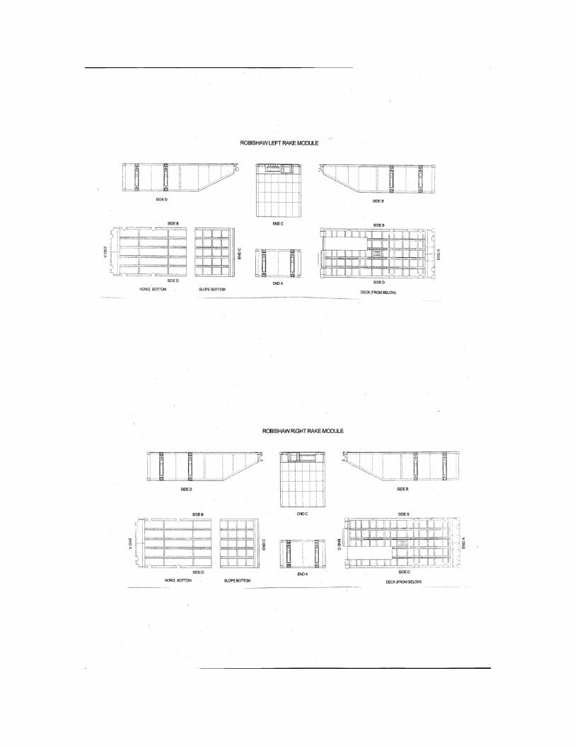
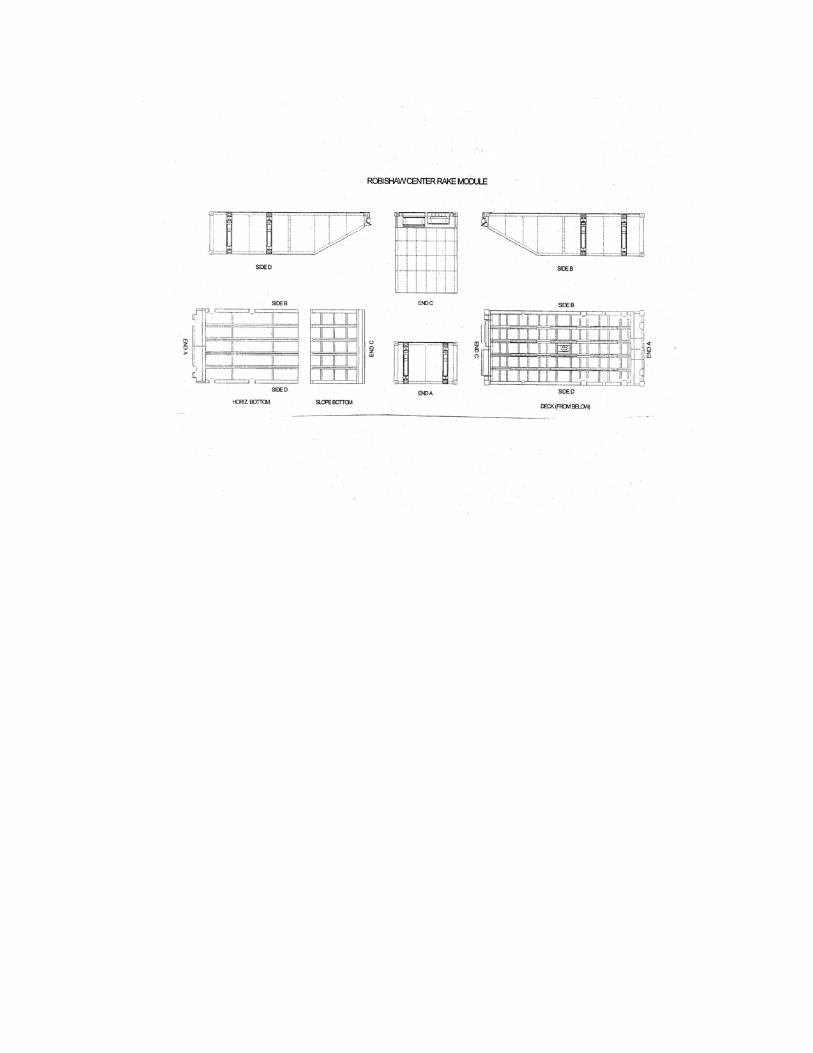
Corner fitting Corner fitting Corner fitting Welds Welds Welds Plate panel Plate panel Plate panel Corner Post Corner Post Corner Post CSC Plate CSC Plate CSC Plate REMARKS: Example of MCS: