Embed Size (px)
Citation preview
By Gregory E. Halsted, David R. Luhr, Wayne S. Adaska
Guide to Cement-Treated Base (CTB)
Guide to Cement-Treated Base (CTB)
Portland Cement Association
5420 Old Orchard RoadSkokie, Illinois 60077-1083847.966.6200 Fax 847.966.9781www.cement.org
ii
Abstract: Cement-treated base (CTB) is a mixed-in-place or central-plant-produced material consisting ofsoil/aggregate, cement, and water that creates a strong and durable stabilized roadway base. This guide toCTB discusses its applications, benefits, design, construction, testing, and performance.
Keywords: cement-treated base, CTB, pavement, subgrade, soil/aggregate, pavement structure, portlandcement, pavement design, mixed-in-place, pugmill, moisture-density relationship, compressive strength, mixdesign, Tube Suction Test, processing, scarification, pre-wetting, reflective cracking, soil-cement.
Reference: Halsted, Gregory, E.; Luhr, David, R.; Adaska, Wayne, S., Guide to Cement-Treated Base (CTB),EB236 Portland Cement Association, Skokie, Illinois, USA, 2006, 20 pages.
About the Authors: Gregory E. Halsted, P.E., Pavements Engineer, Portland Cement Association, PostOffice Box 5113, Bellingham, Washington 98227-5113, USA.
David R. Luhr, PhD, P.E., Program Manager, Portland Cement Association, Post Office Box 5895, Cary, NorthCarolina 27511, USA.
Wayne S. Adaska, P.E., Director of Public Works, Portland Cement Association, 5420 Old Orchard Road,Skokie, Illinois 60077-1083, USA.
WARNING: Contact with wet (unhardened) concrete,mortar, cement, or cement mixtures can cause SKIN IRRITA-TION, SEVERE CHEMICAL BURNS (THIRD DEGREE), or SERI-OUS EYE DAMAGE. Frequent exposure may be associatedwith irritant and/or allergic contact dermatitis. Wear water-proof gloves, a long-sleeved shirt, full-length trousers, andproper eye protection when working with these materials. Ifyou have to stand in wet concrete, use waterproof bootsthat are high enough to keep concrete from flowing intothem. Wash wet concrete, mortar, cement, or cementmixtures from your skin immediately. Flush eyes with cleanwater immediately after contact. Indirect contact throughclothing can be as serious as direct contact, so promptlyrinse out wet concrete, mortar, cement, or cement mixturesfrom clothing. Seek immediate medical attention if youhave persistent or severe discomfort.
Portland Cement Association (“PCA”) is a not-for-profit organization and provides this publicationsolely for the continuing education of qualified professionals. THIS PUBLICATION SHOULD ONLY BEUSED BY QUALIFIED PROFESSIONALS who possess all required license(s), who are competent to eval-uate the significance and limitations of the information provided herein, and who accept totalresponsibility for the application of this information. OTHER READERS SHOULD OBTAIN ASSISTANCEFROM A QUALIFIED PROFESSIONAL BEFORE PROCEEDING. PCA AND ITS MEMBERS MAKE NO EXPRESS OR IMPLIED WARRANTY WITH RESPECT TO THIS PUBLI-CATION OR ANY INFORMATION CONTAINED HEREIN. IN PARTICULAR, NO WARRANTY IS MADE OFMERCHANTABILITY OR FITNESS FOR A PARTICULAR PURPOSE. PCA AND ITS MEMBERS DISCLAIMANY PRODUCT LIABILITY (INCLUDING WITHOUT LIMITATION ANY STRICT LIABILITY IN TORT) INCONNECTION WITH THIS PUBLICATION OR ANY INFORMATION CONTAINED HEREIN.
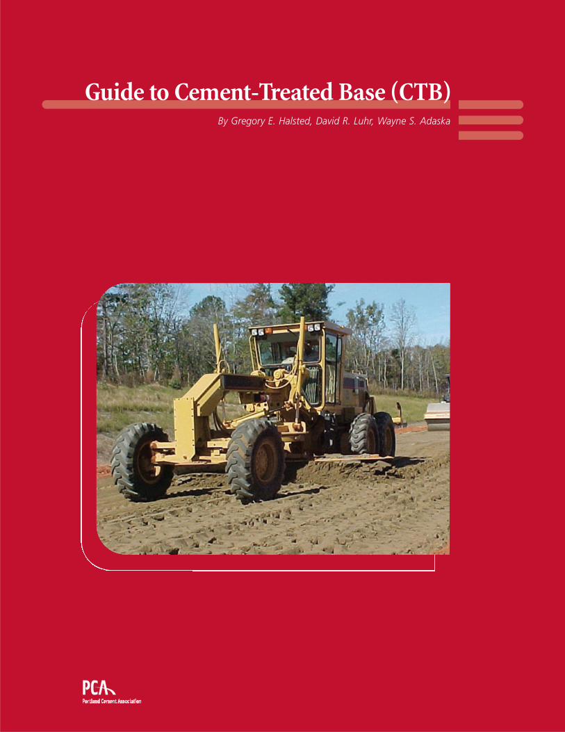
Cover photo: Plant-mixed CTBproject in South Georgia. Courtesy ofMr. Dwane Lewis, Technical ServicesManager, Georgia Department ofTransportation. (IMG24044)
Print HistoryFirst Printing 2006
©2006 Portland Cement Association
ISBN 0-89312-253-X
All rights reserved. No part of thisbook may be reproduced in any formwithout permission in writing fromthe publisher, except by a reviewerwho wishes to quote brief passagesin a review written for inclusion in amagazine or newspaper.
Guide to Cement-Treated Base (CTB)
iii
Table of Contents1 Introduction . . . . . . . . . . . . . . . . . . . . . . . . . . . . . . . . . . . . . . . . . . . . . . . . . . . . . . . . . . 1
Definition . . . . . . . . . . . . . . . . . . . . . . . . . . . . . . . . . . . . . . . . . . . . . . . . . . . . . . . . . . . 1
Performance with CTB . . . . . . . . . . . . . . . . . . . . . . . . . . . . . . . . . . . . . . . . . . . . . . . . . 1
2 Design . . . . . . . . . . . . . . . . . . . . . . . . . . . . . . . . . . . . . . . . . . . . . . . . . . . . . . . . . . . . . . 5
Material Requirements . . . . . . . . . . . . . . . . . . . . . . . . . . . . . . . . . . . . . . . . . . . . . . . . . 5
Pavement Design . . . . . . . . . . . . . . . . . . . . . . . . . . . . . . . . . . . . . . . . . . . . . . . . . . . . . 6
Mix Design . . . . . . . . . . . . . . . . . . . . . . . . . . . . . . . . . . . . . . . . . . . . . . . . . . . . . . . . . . 6
Balanced Design . . . . . . . . . . . . . . . . . . . . . . . . . . . . . . . . . . . . . . . . . . . . . . . . . . . . . . 7
Moisture Sensitivity . . . . . . . . . . . . . . . . . . . . . . . . . . . . . . . . . . . . . . . . . . . . . . . . . . . . 8
3 Construction . . . . . . . . . . . . . . . . . . . . . . . . . . . . . . . . . . . . . . . . . . . . . . . . . . . . . . . . . 9
General Requirements. . . . . . . . . . . . . . . . . . . . . . . . . . . . . . . . . . . . . . . . . . . . . . . . . . 9
Mixed-In-Place Method . . . . . . . . . . . . . . . . . . . . . . . . . . . . . . . . . . . . . . . . . . . . . . . . . 10
Central-Plant Method . . . . . . . . . . . . . . . . . . . . . . . . . . . . . . . . . . . . . . . . . . . . . . . . . . 11
Compaction, Finish, and Cure . . . . . . . . . . . . . . . . . . . . . . . . . . . . . . . . . . . . . . . . . . . . 12
Surfacing . . . . . . . . . . . . . . . . . . . . . . . . . . . . . . . . . . . . . . . . . . . . . . . . . . . . . . . . . . . 13
Reflective Cracking . . . . . . . . . . . . . . . . . . . . . . . . . . . . . . . . . . . . . . . . . . . . . . . . . . . . 13
4 Suggested Construction Specification for Cement-Treated Base . . . . . . . . . . . . . . . 15

iv
Guide to Cement-Treated Base (CTB)
1
1 Introduction
Definition
Cement-treated base (CTB) is a general term that applies toan intimate mixture of native soils and/or manufacturedaggregates with measured amounts of portland cement andwater that hardens after compaction and curing to form astrong, durable, frost resistant paving material. Otherdescriptions such as soil-cement base, cement-treated aggre-gate base, cement-stabilized roadbed, and cement-stabilizedbase are sometimes used.
CTB can be mixed in place using on-site materials, or mixedin a central plant using selected material (often manufacturedaggregates). Mixed-in-place CTB is compacted after blend-ing, and CTB mixed in a central plant is hauled to the place-ment area in dump trucks and placed on the roadway usinga grader, paver, or Jersey-type spreader. A bituminous wear-ing course or portland cement concrete is placed on top ofthe CTB to complete the pavement.
Performance with CTB
While the concept of stabilizing soils and aggregates forpavement purposes has been around for more than a century,engineered CTB was first used in 1935 to improve the road-bed for State Highway 41 near Johnsonville, South Carolina.Today, thousands of miles of CTB pavements in every state inthe United States and in all the Canadian provinces are pro-viding good service at low maintenance costs.
CTB is widely used as a pavement base for highways, roads,streets, parking areas, airports, industrial facilities, and mate-rials handling and storage areas. The structural propertiesof CTB depend on the soil/aggregate material, quantity ofcement, curing conditions, and age. Typical properties ofCTB material are shown in Table 1.
The advantages of CTB are many:
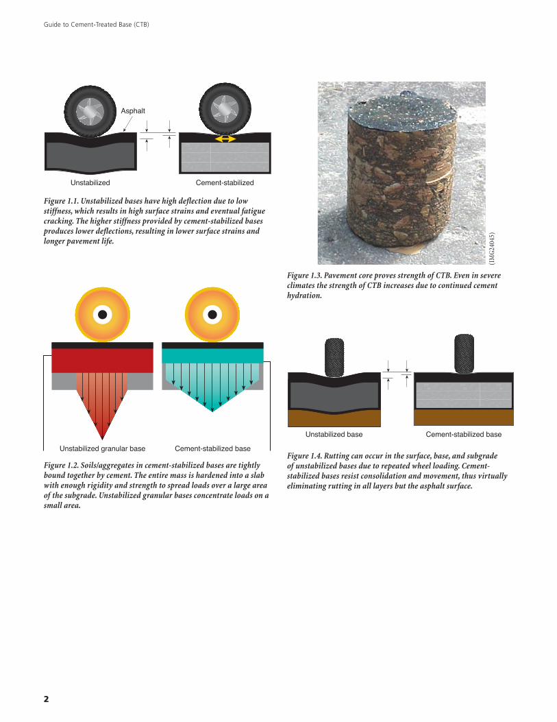
• CTB provides a stiffer and stronger base than an unboundgranular base. A stiffer base reduces deflections due totraffic loads, which results in lower strains in the asphaltsurface. This delays the onset of surface distress, suchas fatigue cracking, and extends pavement life (seeFigure 1.1).
• CTB thicknesses are less than those required for granularbases carrying the same traffic because the loads aredistributed over a large area (see Figure 1.2). The stronguniform support provided by CTB results in reducedstresses applied to the subgrade. A thinner cement-stabilized section can reduce subgrade stresses more thana thicker layer of untreated aggregate base. Subgradefailures, potholes, and road roughness are thus reduced.CTB’s slab-like characteristics and beam strength areunmatched by granular bases that can fail when interlockis lost. Figure 1.3 is a core of completed CTB showing thetightly bound soil/aggregate.
• A wide variety of in-situ soils and manufactured aggre-gates can be used for CTB. This eliminates the need tohaul in expensive select granular aggregates.
Table 1. Properties of CTB
Property 7-Day values
Compressive strength 300 – 800 psi (2.1 – 5.5 MPa)
Modulus of rupture 100 – 200 psi (0.7 – 1.4 MPa)
Modulus of elasticity600,000 – 1,000,000 psi(4,100 - 6,900 MPa)
Poisson’s ratio 0.15
Guide to Cement-Treated Base (CTB)
2
Asphalt
Unstabilized Cement-stabilized
Figure 1.1. Unstabilized bases have high deflection due to lowstiffness, which results in high surface strains and eventual fatiguecracking. The higher stiffness provided by cement-stabilized basesproduces lower deflections, resulting in lower surface strains andlonger pavement life.
Cement-stabilized baseUnstabilized granular base
Figure 1.2. Soils/aggregates in cement-stabilized bases are tightlybound together by cement. The entire mass is hardened into a slabwith enough rigidity and strength to spread loads over a large areaof the subgrade. Unstabilized granular bases concentrate loads on asmall area.
Figure 1.3. Pavement core proves strength of CTB. Even in severeclimates the strength of CTB increases due to continued cementhydration.
Unstabilized base Cement-stabilized base
Figure 1.4. Rutting can occur in the surface, base, and subgradeof unstabilized bases due to repeated wheel loading. Cement-stabilized bases resist consolidation and movement, thus virtuallyeliminating rutting in all layers but the asphalt surface.
(IM
G24
045)
3
• The construction operation progresses quickly with littledisruption to the traveling public. It can be accomplishedwhile still maintaining traffic.
• Rutting is reduced in a CTB pavement. Loads from chan-nelized traffic will displace unbound granular materialbeneath flexible surface pavements (see Figure 1.4).
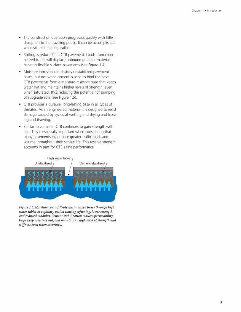
• Moisture intrusion can destroy unstabilized pavementbases, but not when cement is used to bind the base.CTB pavements form a moisture-resistant base that keepswater out and maintains higher levels of strength, evenwhen saturated, thus reducing the potential for pumpingof subgrade soils (see Figure 1.5).
• CTB provides a durable, long-lasting base in all types ofclimates. As an engineered material it is designed to resistdamage caused by cycles of wetting and drying and freez-ing and thawing.
• Similar to concrete, CTB continues to gain strength withage. This is especially important when considering thatmany pavements experience greater traffic loads andvolume throughout their service life. This reserve strengthaccounts in part for CTB's fine performance.
Chapter 1 • Introduction
High water table
Unstabilized Cement-stabilized
Figure 1.5. Moisture can infiltrate unstabilized bases through highwater tables or capillary action causing softening, lower strength,and reduced modulus. Cement stabilization reduces permeability,helps keep moisture out, and maintains a high level of strength andstiffness even when saturated.

Guide to Cement-Treated Base (CTB)
4
5
2 Design
Material Requirements
Because CTB can either be constructed in place or plantmixed, the correct selection of soil and aggregate materials isimportant to the production of quality CTB mixes. Thisknowledge of the ingredients is coupled with theconstruction requirements and specifications for theintended project in order to ensure a CTB mix that meets thedesign and performance objectives. The design proceduresmentioned in this document relate to all climate areas whenthe quality of the CTB meets requirements for aggregate andcement factor as described below, and when it is properlyconstructed.
The soil and aggregate materials for use in CTB may consistof (1) any combination of gravel, stone, sand, silt, and clay;(2) miscellaneous material such as caliche, scoria, slag, sand-shell, cinders, and ash; (3) waste material from aggregateproduction plants; (4) high-quality crushed stone and gravelbase course aggregates; or (5) old flexible pavements, in-cluding the pulverized bituminous surface and stone orgravel base course.
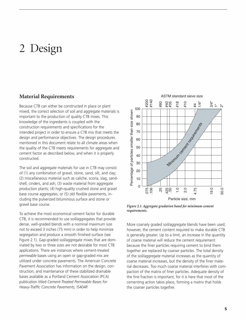
To achieve the most economical cement factor for durableCTB, it is recommended to use soil/aggregates that providedense, well-graded blends with a nominal maximum sizenot to exceed 3 inches (75 mm) in order to help minimizesegregation and produce a smooth finished surface (seeFigure 2.1). Gap-graded soil/aggregate mixes that are dom-inated by two or three sizes are not desirable for most CTBapplications. There are instances where cement-treatedpermeable bases using an open or gap-graded mix areutilized under concrete pavements. The American ConcretePavement Association has information on the design, con-struction, and maintenance of these stabilized drainablebases available as a Portland Cement Association (PCA)publication titled Cement-Treated Permeable Bases forHeavy-Traffic Concrete Pavements, IS404P.
More coarsely graded soil/aggregate blends have been used;however, the cement content required to make durable CTBis generally greater. Up to a limit, an increase in the quantityof coarse material will reduce the cement requirementbecause the finer particles requiring cement to bind themtogether are replaced by coarser particles. The total densityof the soil/aggregate material increases as the quantity ofcoarse material increases, but the density of the finer mate-rial decreases. Too much coarse material interferes with com-paction of the matrix of finer particles. Adequate density ofthe fine fraction is important, for it is here that most of thecementing action takes place, forming a matrix that holdsthe coarser particles together.
Minim
umce
men
t req
uire
men
ts
100
90
80
70
60
50
40
20
10
0
30
#140
#200
.075
.106 .25
.425 .50
1.0
2.0
4.75
19.0
50.0
#60
#40
#35
#18
#10
#4 1/4"
3/4"
2"1"
Particle size, mm
ASTM standard sieve size
Per
cent
age
of p
artic
les
smal
ler
than
siz
e sh
own
Figure 2.1. Aggregate gradation band for minimum cementrequirements.
Guide to Cement-Treated Base (CTB)
6
Pavement Design
The ability of a pavement base to carry loads depends on thestrength of the base material and the thickness of the baselayer. A thin, but strong base can theoretically carry the sameload as a thick, but weaker base. However, the thin, strongbase should be avoided because it can become brittle andfracture, resulting in potential reflection cracks in the pave-ment surface (see page 13 under Reflective Cracking). Whenselecting thicknesses for CTB pavements, a thicker base withless strength is usually preferred (see discussion of BalancedDesign on page 7). Today's more powerful mixing and com-pacting equipment has made the job of constructing thickerCTB layers much easier and more reliable compared withequipment used years ago.
CTB possesses its own unique structural characteristics. CTBpavements are designed for both economy and long servicelife. The factors analyzed to determine the CTB and surfacedesign thickness are:
1. Subgrade strength
2. Pavement design period
3. Traffic, including volume and distribution of axle weights(single- and tandem-axle loading configurations ofconventional trucks)
In most cases, engineers have the option of selecting a CTBdesign procedure for the pavement structure. The 1993American Association of State Highway and TransportationOfficials (AASHTO) design guide for pavement structures, forexample, uses a Structural Layer Coefficient to model basematerials. In addition, PCA has three separate informationsheets that present detailed design methods for streets andhighways (PCA publication Thickness Design for Soil-CementPavements, EB068), airfields (PCA publication Soil-CementPavements for Light Aircraft, IS203), and special heavy-loadareas such as container ports, log handling areas, and otherheavy industrial loads (PCA publication Thickness Design ofSoil-Cement Pavements for Heavy Industrial Vehicles, IS187).
These three PCA design procedures are based on informationfrom several sources including research, theory, full-scale testpavements, and the performance of pavements in service. Aresearch program conducted by PCA correlates the designinformation from these sources and results in a proceduredeveloped uniquely for CTB materials.
A few 4 to 5-inch (100 to 125 mm) thick pavements havebeen constructed and have held up well under favorable
conditions of light traffic and strong subgrade support; how-ever, most CTB pavements in service are 6 inches (150 mm)thick. This thickness has proved satisfactory for the serviceconditions of secondary roads, residential streets, and light-traffic airfields.
Many miles of 7 to 9-inch (175 to 225 mm) thick pavementsare in service on primary and heavy-traffic secondary roads.On interstate highways, thickness ranges from 6 to 12 inches(150 to 300 mm) have been incorporated into the totalpavement structures. CTB pavements with thicknesses of12 inches (300 mm) or more are not numerous, although afew airport projects have been built with thicknesses of upto 15 inches (375 mm). CTB thicknesses exceeding 12 inches(300 mm) are difficult to compact in one lift. For designthicknesses greater than 12 inches (300 mm) multiple liftconstruction is used.
CTB can also be used as a subbase layer under concrete pave-ments to prevent mud-pumping of fine-grained subgradesoils under wet conditions and heavy truck traffic. In additionto preventing mud-pumping, CTB provides a uniform, strongsupport for the pavement, provides a firm, stable workingplatform for construction equipment, prevents infiltration ofsubgrade into the subbase, prevents subbase consolidationunder traffic, and provides increased load transfer atpavement joints.
Mix Design
Designing the proper amount of water and cement for CTBis not only important to obtain a good final product, but alsoprovides important information for quality control duringconstruction. The PCA publication Soil-Cement LaboratoryHandbook, EB052, provides comprehensive information ontesting procedures for determining the appropriate cementcontent, water content, and compaction requirements forCTB materials. Research has shown that cement-stabilizedmaterials have better strength and performance when theyare fully compacted, so determining final compaction densityis fundamental to the design procedure.
Compaction density is determined through the Standard TestMethod for Moisture-Density Relations of Soil-CementMixtures (ASTM D 558). The test procedure is similar toASTM D 698 which uses the standard compaction effortused for soil and aggregate. The ASTM D 558 test methodis a common (as well as inexpensive) procedure for mostconstruction testing labs. The test can be performed in eitherthe laboratory or the field, and determines the maximum
7
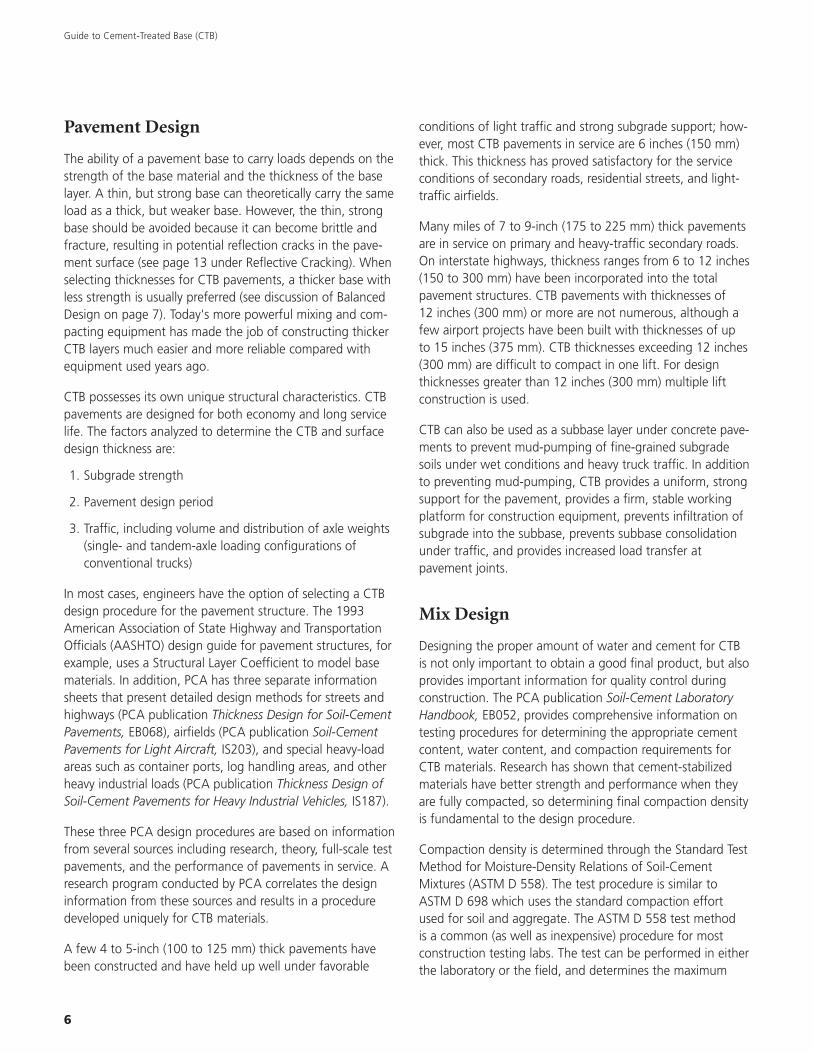
dry density (unit weight) for the CTB mix, and the optimum-moisture content. Figure 2.2 shows a typical compactioncurve from the ASTM D 558 test method. If the mix is toodry, there is not enough moisture available to lubricate theparticles into a denser formation. If the mix is too wet, theexcess moisture pushes the particles apart.
content is not known at this stage of the design, an assumedcement content can be chosen in conducting the test. Table1 in PCA publication Soil-Cement Laboratory Handbook maybe used to estimate cement content for the moisture-densitytest. Cement contents within a range of one or two percentwill not significantly influence the results. However, once theexact cement content is established, a moisture-density testshould be conducted with the established cement content inorder to determine the control factors for field construction.
Using the optimum moisture content from the initial moisture-density test, a series of CTB specimens are prepared at dif-ferent cement contents to determine compressive strength.Typically three cement contents are chosen (for example,2%, 5%, and 8%). Caution should be used when cementcontents exceed 8% as increased shrinkage may occur,resulting in reflection cracking. It is recommended that aminimum of two specimens be prepared for each cementcontent. These specimens are moist cured for 7 days, andthen tested for unconfined compressive strength accordingto ASTM Standard Test Method for Compressive Strength ofMolded Soil-Cement Cylinders (ASTM D 1633). This will givea range of strength results in which to determine therequired cement content.
Balanced Design
CTB must be strong enough to provide adequate pavementsupport for the current and future traffic loading conditions.In addition, CTB needs to remain hard and durable and beable to resist the volume changes or hydraulic pressurescaused by freezing and thawing and moisture changes thatcould gradually break down the cementitious bonds.
In general, a cement content that will provide a 7-dayunconfined compressive strength between 300 and 400 psi(2.1 and 2.8 MPa) is satisfactory for most mixed-in-place CTBapplications. Because there is usually more coarse aggregateinvolved, strengths for plant mixed CTB can be as high as800 psi (5.5 MPa). Even higher strengths may be achieveddepending on project requirements. However, the mainreason for limiting strength is to minimize shrinkage crackingcaused by higher cement and water content. Experience hasshown that high strengths can cause additional cracks toreflect through the pavement surface. The objective is tohave a “balanced design,” where enough cement is used sothat the resulting stabilized base is strong, durable, and rela-tively impermeable, but not so strong that it results in othertypes of distress in the pavement.
Chapter 2 • Design
5% 7% 9% 11%
Moisture contentASTM D 558
13%
Optimum moisture content
Maximum dry density
15% 17%
125
120
115
110
105
100
Dry
den
sity
(lb
/cf)
100 lb/cf = 1600 kg/cm
Moisture-Density Relationship
Figure 2.2. Determining the Maximum Dry Density and OptimumMoisture Content (ASTM D 558).
The amount of water in the mix is called the water (moisture)content, and is defined as the weight of water in the mix(expressed as a percentage of the dry material):
water content, = weight of water in mix X 100w (%) weight of oven-dry CTB material
The amount of cement is normally expressed in percentageon a weight or volume basis. The cement content by weightis based on the oven-dry weight of the soil/aggregate only(cement is not included) and is expressed as:
cement content, = weight of cement in mix X 100c (%) weight of oven-dry soil/aggregate
The amount of water and cement required in the mix willdepend upon the project specified strength and gradation ofthe soil/aggregate materials. Typical specifications for mostmixed-in-place and plant mixed CTB call for a minimum of100% passing the 3-inch (75 mm) sieve, 95% passing the2-inch (50 mm) sieve, and 55% passing the No. 4 (4.75 mm)sieve. If the blend contains more fine-grained soil, then morecement and water will be required because of the largersurface area of the finer particles.
The next step is to conduct a moisture-density test to deter-mine the moisture content for molding the CTB specimensfor compressive strength testing. Since the exact cement
Guide to Cement-Treated Base (CTB)
8
Moisture Sensitivity
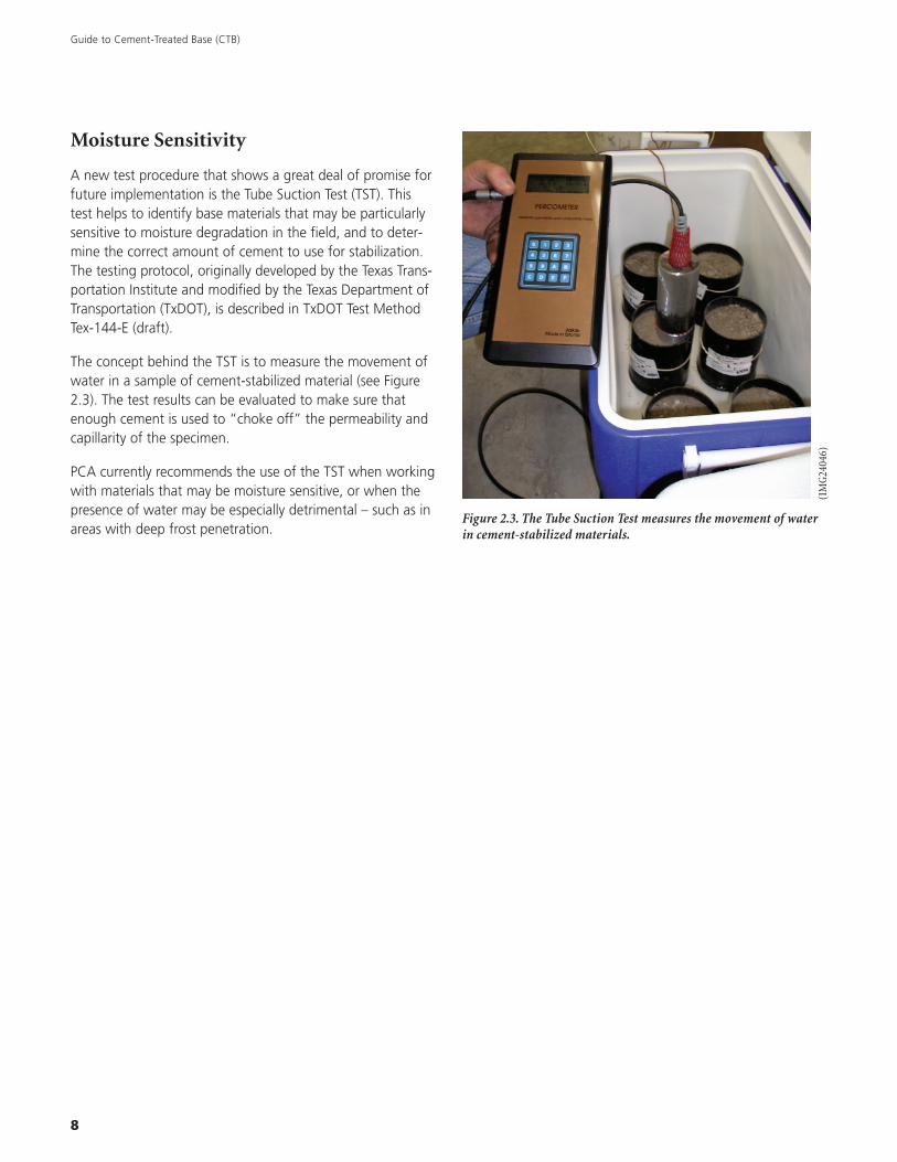
A new test procedure that shows a great deal of promise forfuture implementation is the Tube Suction Test (TST). Thistest helps to identify base materials that may be particularlysensitive to moisture degradation in the field, and to deter-mine the correct amount of cement to use for stabilization.The testing protocol, originally developed by the Texas Trans-portation Institute and modified by the Texas Department ofTransportation (TxDOT), is described in TxDOT Test MethodTex-144-E (draft).
The concept behind the TST is to measure the movement ofwater in a sample of cement-stabilized material (see Figure2.3). The test results can be evaluated to make sure thatenough cement is used to “choke off” the permeability andcapillarity of the specimen.
PCA currently recommends the use of the TST when workingwith materials that may be moisture sensitive, or when thepresence of water may be especially detrimental – such as inareas with deep frost penetration.
Figure 2.3. The Tube Suction Test measures the movement of waterin cement-stabilized materials.
(IM
G24
046)
9
3 Construction
General Requirements
In CTB construction, the objective is to thoroughly mix asoil/aggregate material with the correct quantity of portlandcement and enough water to permit maximum compaction.The resulting CTB must be adequately cured to provide thenecessary moisture needed for cement hydration to fullyharden the CTB mixture.
The fundamental control factors for quality CTB are:
1. Proper cement content
2. Adequate moisture content
3. Thorough mixing
4. Adequate compaction
5. Proper curing
The construction steps are
1. Preparation
• Checking and calibration of equipment
• Correcting any soft subgrade areas
• Shaping the area to proper crown and grade
2A. Mixed-in-Place Processing
• Spreading portland cement and mix
• Applying water and mix
• Compacting
• Finishing
• Curing
2B. Central Plant Processing
• Mixing soil/aggregate material, cement, and water incentral plant
• Hauling and spreading
• Compacting
• Finishing
• Curing
The area to be paved must be shaped to proper crown andgrade. Proper compaction is one of the fundamental require-ments for CTB construction. If the subgrade is soft and can-not support the compaction equipment, adequate densitywill not be obtained. Therefore, soft areas should be locatedand made stable before CTB material is mixed or placed.
Soil/aggregate, cement, and water can be mixed in a centralmixing plant, or mixed in place using traveling mixingmachines. The mixing methods include:
1. Single-shaft in-place mixing equipment
2. Central mixing plants
• Continuous-flow-type pugmill
• Batch-type pugmill
• Rotary-drum mixer
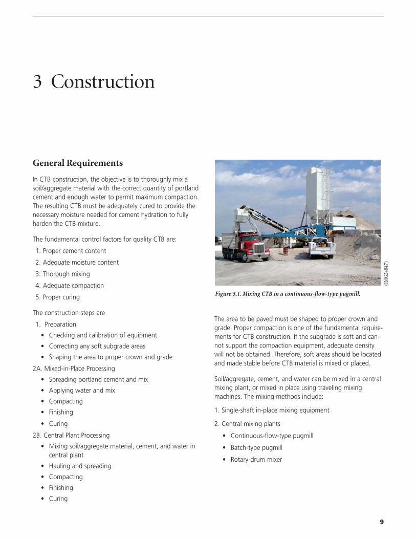
Figure 3.1. Mixing CTB in a continuous-flow-type pugmill.
(IM
G24
047)
Guide to Cement-Treated Base (CTB)
10
Mixed-In-Place Method
Guide stakes should be set to control the width of treatmentand to guide the operators during construction.
Soil/aggregate in required quantity should be distributed onan accurately graded, well-compacted subgrade in an evenlayer or in a uniform windrow, depending upon the type ofmixing equipment to be used.
For maximum efficiency the day’s work should be brokendown into several adjacent sections rather than one or twolong sections.
Bulk cement is normally hauled to the jobsite in bulk trans-port trucks. Cement is then transferred to job cementstorage trucks, which are usually enclosed or fitted withcanvas covers. Cement is transferred into the cement storagetrucks pneumatically by a screw or belt conveyor. Prior tocement spreading, truckloads of cement are weighed onportable platform scales or at a nearby scale.
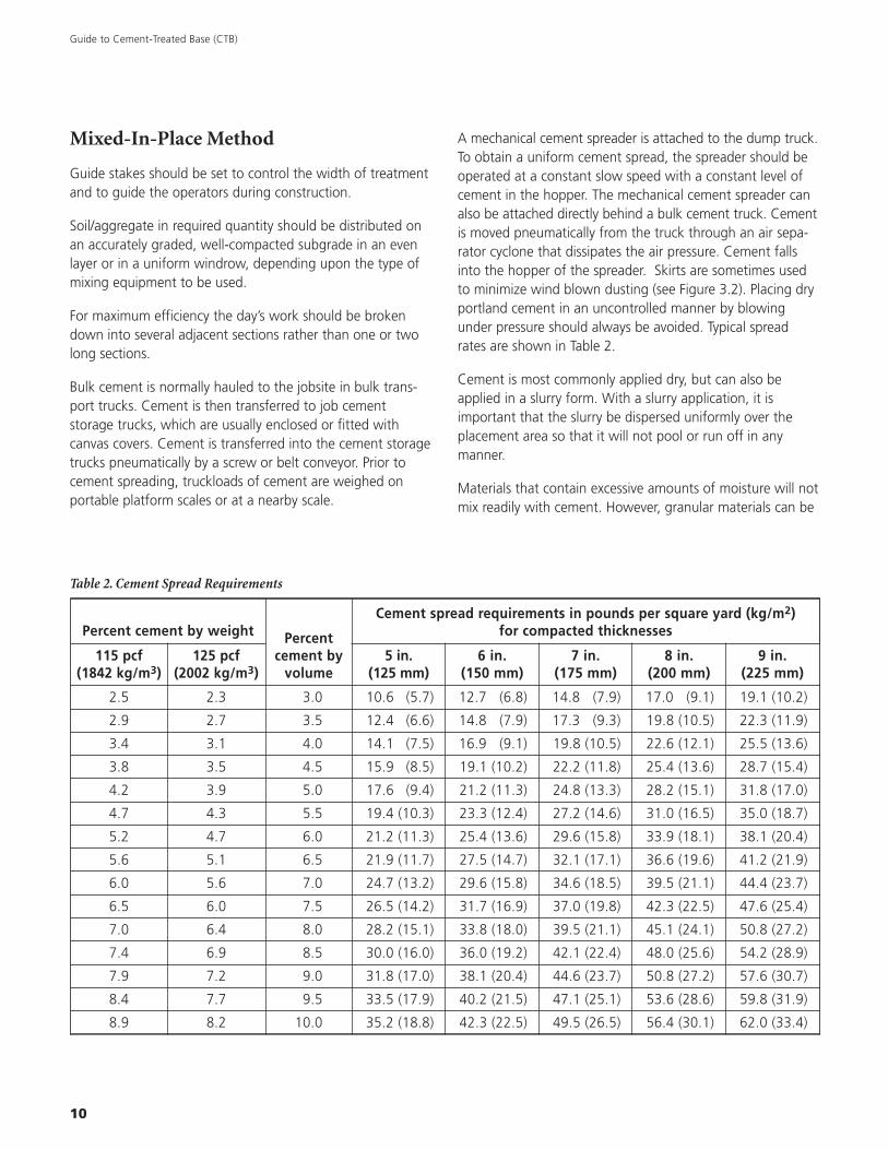
A mechanical cement spreader is attached to the dump truck.To obtain a uniform cement spread, the spreader should beoperated at a constant slow speed with a constant level ofcement in the hopper. The mechanical cement spreader canalso be attached directly behind a bulk cement truck. Cementis moved pneumatically from the truck through an air sepa-rator cyclone that dissipates the air pressure. Cement fallsinto the hopper of the spreader. Skirts are sometimes usedto minimize wind blown dusting (see Figure 3.2). Placing dryportland cement in an uncontrolled manner by blowingunder pressure should always be avoided. Typical spreadrates are shown in Table 2.
Cement is most commonly applied dry, but can also beapplied in a slurry form. With a slurry application, it isimportant that the slurry be dispersed uniformly over theplacement area so that it will not pool or run off in anymanner.
Materials that contain excessive amounts of moisture will notmix readily with cement. However, granular materials can be
Percent cement by weight Percentcement by
volume
Cement spread requirements in pounds per square yard (kg/m2)for compacted thicknesses
115 pcf(1842 kg/m3)
125 pcf(2002 kg/m3)
5 in.(125 mm)
6 in.(150 mm)
7 in.(175 mm)
8 in.(200 mm)
9 in.(225 mm)
2.5 2.3 3.0 10.6 (5.7) 12.7 (6.8) 14.8 (7.9) 17.0 (9.1) 19.1 (10.2)
2.9 2.7 3.5 12.4 (6.6) 14.8 (7.9) 17.3 (9.3) 19.8 (10.5) 22.3 (11.9)
3.4 3.1 4.0 14.1 (7.5) 16.9 (9.1) 19.8 (10.5) 22.6 (12.1) 25.5 (13.6)
3.8 3.5 4.5 15.9 (8.5) 19.1 (10.2) 22.2 (11.8) 25.4 (13.6) 28.7 (15.4)
4.2 3.9 5.0 17.6 (9.4) 21.2 (11.3) 24.8 (13.3) 28.2 (15.1) 31.8 (17.0)
4.7 4.3 5.5 19.4 (10.3) 23.3 (12.4) 27.2 (14.6) 31.0 (16.5) 35.0 (18.7)
5.2 4.7 6.0 21.2 (11.3) 25.4 (13.6) 29.6 (15.8) 33.9 (18.1) 38.1 (20.4)
5.6 5.1 6.5 21.9 (11.7) 27.5 (14.7) 32.1 (17.1) 36.6 (19.6) 41.2 (21.9)
6.0 5.6 7.0 24.7 (13.2) 29.6 (15.8) 34.6 (18.5) 39.5 (21.1) 44.4 (23.7)
6.5 6.0 7.5 26.5 (14.2) 31.7 (16.9) 37.0 (19.8) 42.3 (22.5) 47.6 (25.4)
7.0 6.4 8.0 28.2 (15.1) 33.8 (18.0) 39.5 (21.1) 45.1 (24.1) 50.8 (27.2)
7.4 6.9 8.5 30.0 (16.0) 36.0 (19.2) 42.1 (22.4) 48.0 (25.6) 54.2 (28.9)
7.9 7.2 9.0 31.8 (17.0) 38.1 (20.4) 44.6 (23.7) 50.8 (27.2) 57.6 (30.7)
8.4 7.7 9.5 33.5 (17.9) 40.2 (21.5) 47.1 (25.1) 53.6 (28.6) 59.8 (31.9)
8.9 8.2 10.0 35.2 (18.8) 42.3 (22.5) 49.5 (26.5) 56.4 (30.1) 62.0 (33.4)
Table 2. Cement Spread Requirements
11
mixed effectively with moisture contents slightly aboveoptimum.
Procedures for applying water and mixing will depend on thetype of mixing machine used. A thorough mixture of soil/aggregate, cement, and water must be obtained. Uniformityof the mix is easily checked by digging trenches or series ofholes at regular intervals for the full depth of treatment andinspecting the color of the exposed mixture. Uniform colorand texture from top to bottom indicate a satisfactory mix;a streaked appearance indicates insufficient mixing.
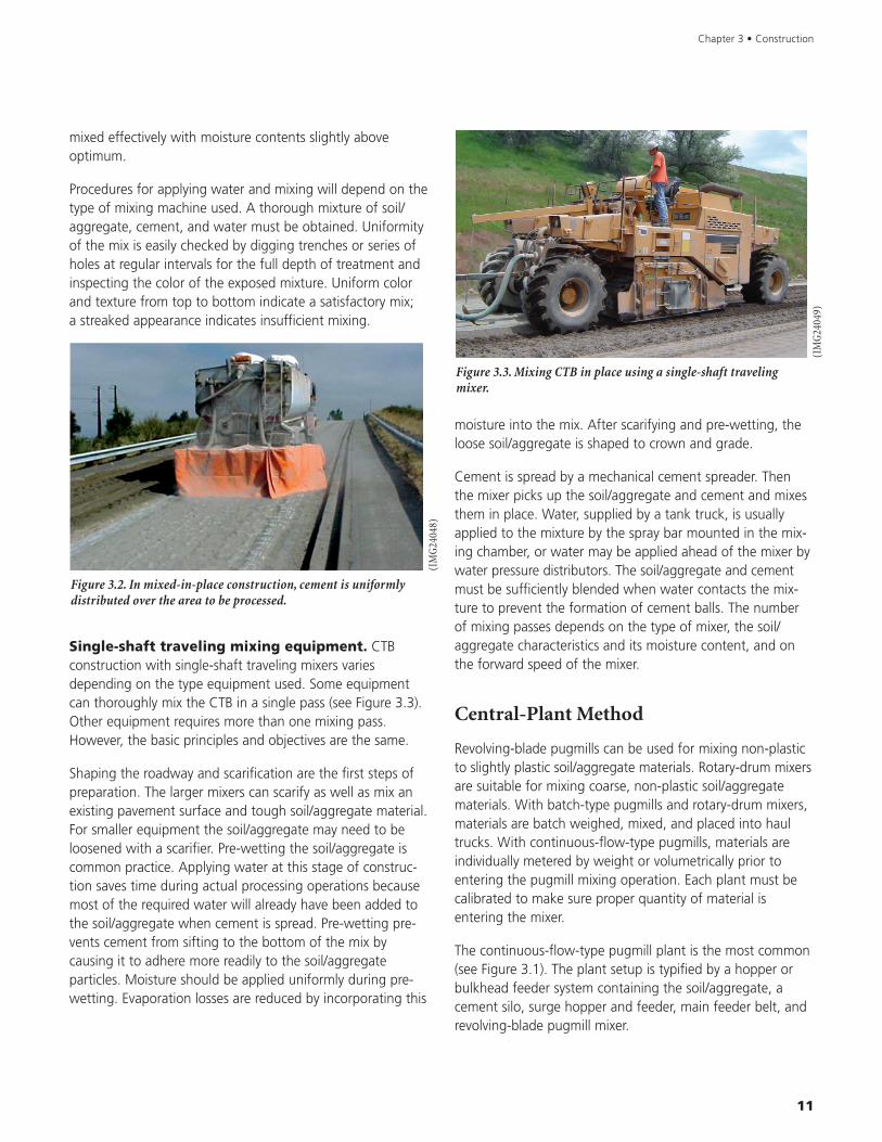
Single-shaft traveling mixing equipment. CTBconstruction with single-shaft traveling mixers variesdepending on the type equipment used. Some equipmentcan thoroughly mix the CTB in a single pass (see Figure 3.3).Other equipment requires more than one mixing pass.However, the basic principles and objectives are the same.
Shaping the roadway and scarification are the first steps ofpreparation. The larger mixers can scarify as well as mix anexisting pavement surface and tough soil/aggregate material.For smaller equipment the soil/aggregate may need to beloosened with a scarifier. Pre-wetting the soil/aggregate iscommon practice. Applying water at this stage of construc-tion saves time during actual processing operations becausemost of the required water will already have been added tothe soil/aggregate when cement is spread. Pre-wetting pre-vents cement from sifting to the bottom of the mix bycausing it to adhere more readily to the soil/aggregateparticles. Moisture should be applied uniformly during pre-wetting. Evaporation losses are reduced by incorporating this
Figure 3.2. In mixed-in-place construction, cement is uniformlydistributed over the area to be processed.
moisture into the mix. After scarifying and pre-wetting, theloose soil/aggregate is shaped to crown and grade.
Cement is spread by a mechanical cement spreader. Thenthe mixer picks up the soil/aggregate and cement and mixesthem in place. Water, supplied by a tank truck, is usuallyapplied to the mixture by the spray bar mounted in the mix-ing chamber, or water may be applied ahead of the mixer bywater pressure distributors. The soil/aggregate and cementmust be sufficiently blended when water contacts the mix-ture to prevent the formation of cement balls. The numberof mixing passes depends on the type of mixer, the soil/aggregate characteristics and its moisture content, and onthe forward speed of the mixer.
Central-Plant Method
Revolving-blade pugmills can be used for mixing non-plasticto slightly plastic soil/aggregate materials. Rotary-drum mixersare suitable for mixing coarse, non-plastic soil/aggregatematerials. With batch-type pugmills and rotary-drum mixers,materials are batch weighed, mixed, and placed into haultrucks. With continuous-flow-type pugmills, materials areindividually metered by weight or volumetrically prior toentering the pugmill mixing operation. Each plant must becalibrated to make sure proper quantity of material isentering the mixer.
The continuous-flow-type pugmill plant is the most common(see Figure 3.1). The plant setup is typified by a hopper orbulkhead feeder system containing the soil/aggregate, acement silo, surge hopper and feeder, main feeder belt, andrevolving-blade pugmill mixer.
Figure 3.3. Mixing CTB in place using a single-shaft travelingmixer.
Chapter 3 • Construction
(IM
G24
048)
(IM
G24
049)
Guide to Cement-Treated Base (CTB)
12
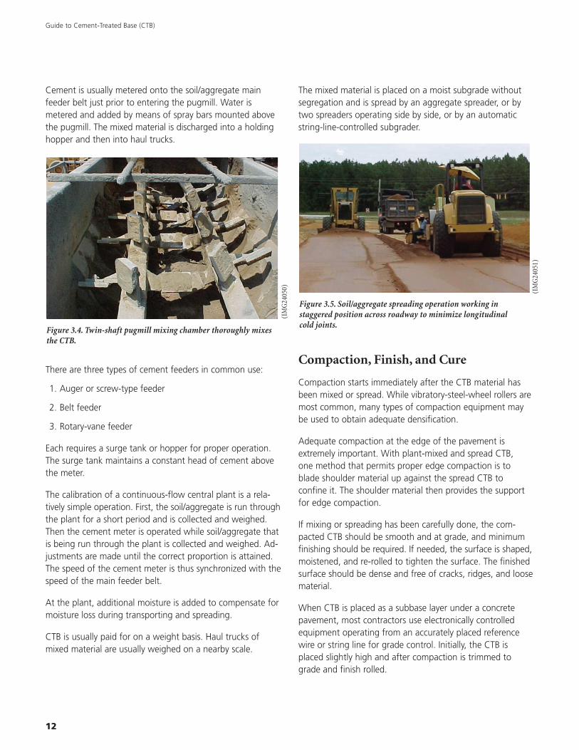
Cement is usually metered onto the soil/aggregate mainfeeder belt just prior to entering the pugmill. Water ismetered and added by means of spray bars mounted abovethe pugmill. The mixed material is discharged into a holdinghopper and then into haul trucks.
There are three types of cement feeders in common use:
1. Auger or screw-type feeder
2. Belt feeder
3. Rotary-vane feeder
Each requires a surge tank or hopper for proper operation.The surge tank maintains a constant head of cement abovethe meter.
The calibration of a continuous-flow central plant is a rela-tively simple operation. First, the soil/aggregate is run throughthe plant for a short period and is collected and weighed.Then the cement meter is operated while soil/aggregate thatis being run through the plant is collected and weighed. Ad-justments are made until the correct proportion is attained.The speed of the cement meter is thus synchronized with thespeed of the main feeder belt.
At the plant, additional moisture is added to compensate formoisture loss during transporting and spreading.
CTB is usually paid for on a weight basis. Haul trucks ofmixed material are usually weighed on a nearby scale.
Figure 3.4. Twin-shaft pugmill mixing chamber thoroughly mixesthe CTB.
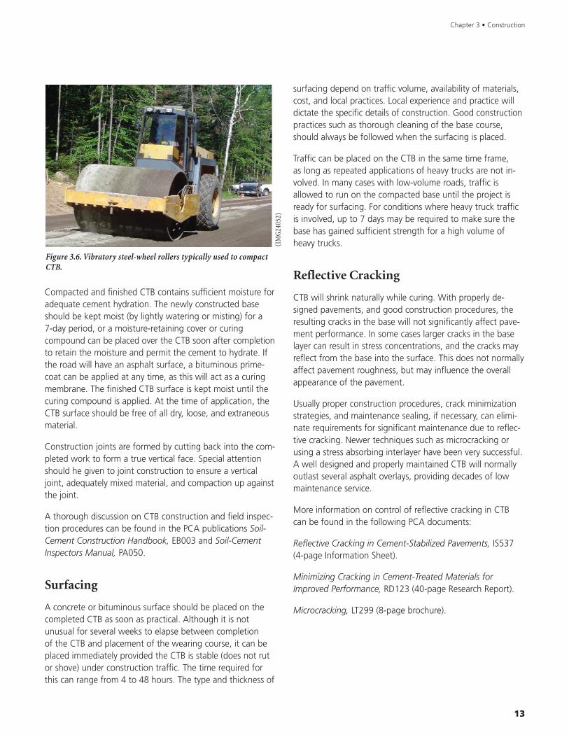
The mixed material is placed on a moist subgrade withoutsegregation and is spread by an aggregate spreader, or bytwo spreaders operating side by side, or by an automaticstring-line-controlled subgrader.
Compaction, Finish, and Cure
Compaction starts immediately after the CTB material hasbeen mixed or spread. While vibratory-steel-wheel rollers aremost common, many types of compaction equipment maybe used to obtain adequate densification.
Adequate compaction at the edge of the pavement isextremely important. With plant-mixed and spread CTB,one method that permits proper edge compaction is toblade shoulder material up against the spread CTB toconfine it. The shoulder material then provides the supportfor edge compaction.
If mixing or spreading has been carefully done, the com-pacted CTB should be smooth and at grade, and minimumfinishing should be required. If needed, the surface is shaped,moistened, and re-rolled to tighten the surface. The finishedsurface should be dense and free of cracks, ridges, and loosematerial.
When CTB is placed as a subbase layer under a concretepavement, most contractors use electronically controlledequipment operating from an accurately placed referencewire or string line for grade control. Initially, the CTB isplaced slightly high and after compaction is trimmed tograde and finish rolled.
Figure 3.5. Soil/aggregate spreading operation working instaggered position across roadway to minimize longitudinalcold joints.
(IM
G24
050) (IM
G24
051)
13
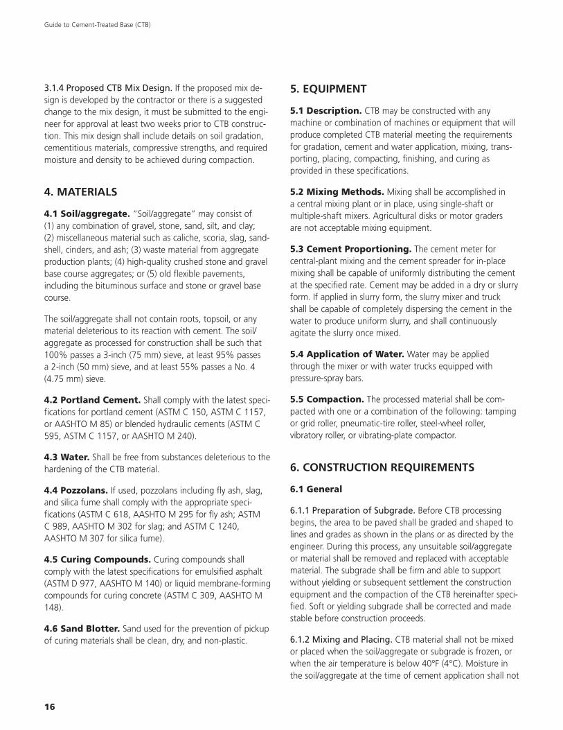
Compacted and finished CTB contains sufficient moisture foradequate cement hydration. The newly constructed baseshould be kept moist (by lightly watering or misting) for a7-day period, or a moisture-retaining cover or curingcompound can be placed over the CTB soon after completionto retain the moisture and permit the cement to hydrate. Ifthe road will have an asphalt surface, a bituminous prime-coat can be applied at any time, as this will act as a curingmembrane. The finished CTB surface is kept moist until thecuring compound is applied. At the time of application, theCTB surface should be free of all dry, loose, and extraneousmaterial.
Construction joints are formed by cutting back into the com-pleted work to form a true vertical face. Special attentionshould he given to joint construction to ensure a verticaljoint, adequately mixed material, and compaction up againstthe joint.
A thorough discussion on CTB construction and field inspec-tion procedures can be found in the PCA publications Soil-Cement Construction Handbook, EB003 and Soil-CementInspectors Manual, PA050.
Surfacing
A concrete or bituminous surface should be placed on thecompleted CTB as soon as practical. Although it is notunusual for several weeks to elapse between completionof the CTB and placement of the wearing course, it can beplaced immediately provided the CTB is stable (does not rutor shove) under construction traffic. The time required forthis can range from 4 to 48 hours. The type and thickness of
Figure 3.6. Vibratory steel-wheel rollers typically used to compactCTB.
surfacing depend on traffic volume, availability of materials,cost, and local practices. Local experience and practice willdictate the specific details of construction. Good constructionpractices such as thorough cleaning of the base course,should always be followed when the surfacing is placed.
Traffic can be placed on the CTB in the same time frame,as long as repeated applications of heavy trucks are not in-volved. In many cases with low-volume roads, traffic isallowed to run on the compacted base until the project isready for surfacing. For conditions where heavy truck trafficis involved, up to 7 days may be required to make sure thebase has gained sufficient strength for a high volume ofheavy trucks.
Reflective Cracking
CTB will shrink naturally while curing. With properly de-signed pavements, and good construction procedures, theresulting cracks in the base will not significantly affect pave-ment performance. In some cases larger cracks in the baselayer can result in stress concentrations, and the cracks mayreflect from the base into the surface. This does not normallyaffect pavement roughness, but may influence the overallappearance of the pavement.
Usually proper construction procedures, crack minimizationstrategies, and maintenance sealing, if necessary, can elimi-nate requirements for significant maintenance due to reflec-tive cracking. Newer techniques such as microcracking orusing a stress absorbing interlayer have been very successful.A well designed and properly maintained CTB will normallyoutlast several asphalt overlays, providing decades of lowmaintenance service.
More information on control of reflective cracking in CTBcan be found in the following PCA documents:
Reflective Cracking in Cement-Stabilized Pavements, IS537(4-page Information Sheet).
Minimizing Cracking in Cement-Treated Materials forImproved Performance, RD123 (40-page Research Report).
Microcracking, LT299 (8-page brochure).
Chapter 3 • Construction
(IM
G24
052)

Guide to Cement-Treated Base (CTB)
14
15
4 Suggested Construction Specificationfor Cement-Treated Base
1. GENERAL
1.1 Description. Cement-treated base (CTB) shall consistof soil/aggregate, portland cement, and water proportioned,mixed, placed, compacted, and cured in accordance withthese specifications; and shall conform to the lines, grades,thicknesses, and typical cross sections shown in the plans.
These suggested specifications cover construction of CTBcourse, also referred to in some areas as soil-cement base,cement-treated aggregate base, cement-stabilized base, andother names.
1.2 Caveat. These specifications are intended to serve as aguide to format and content for normal CTB construction.Most projects have features or requirements that should beincorporated in the project documents.
2. REFERENCED DOCUMENTS
American Society for Testing and Materials (ASTM)with corresponding American Association ofState Highway and Transportation Officials(AASHTO) designations:
ASTM
C 150 Specification for Portland Cement (AASHTO M 85)
C 309 Specification for Liquid Membrane-FormingCompounds for Curing Concrete (AASHTO M 148)
C 595 Specification for Blended Hydraulic Cements(AASHTO M 240)
C 618 Specification for Coal Fly Ash and Raw or CalcinedNatural Pozzolan for Use in Concrete (AASHTOM 295)
C 989 Specification for Ground Granulated Blast-FurnaceSlag for Use in Concrete and Mortars (AASHTOM 302)
C 1240 Specification for Silica Fume Used in CementitiousMixtures (AASHTO M 307)
D 558 Moisture-Density (Unit Weight) Relations of Soil-Cement Mixtures (AASHTO T 134)
D 977 Specification for Emulsified Asphalt (AASHTOM 140)
D 1556 Density and Unit Weight of Soil in Place by theSand-Cone Method (AASHTO T 191)
D 2167 Density and Unit Weight of Soil in Place by theRubber Balloon Method
D 2922 Density of Soil and Soil-Aggregate in Place byNuclear Methods (Shallow Depth) (AASHTO T 310)
3. SUBMITTALS
3.1 Submittal Requirements. The contractor shallsubmit the following to the engineer at least 30 days beforestart of any production of CTB:
3.1.1 Certifications. Certifications for portland cement andsupplementary cementitious materials as required by theengineer.
3.1.2 Specifications. Manufacturers’ data and specificationsfor equipment including capacities to be used in mixing,hauling, placing, and compacting CTB.
3.1.3 Plant Layout. If central-plant mixing, submit layout ofplant location showing mixing plant, cement and aggregatestorage, and water supply.
Guide to Cement-Treated Base (CTB)
16
3.1.4 Proposed CTB Mix Design. If the proposed mix de-sign is developed by the contractor or there is a suggestedchange to the mix design, it must be submitted to the engi-neer for approval at least two weeks prior to CTB construc-tion. This mix design shall include details on soil gradation,cementitious materials, compressive strengths, and requiredmoisture and density to be achieved during compaction.
4. MATERIALS
4.1 Soil/aggregate. “Soil/aggregate” may consist of(1) any combination of gravel, stone, sand, silt, and clay;(2) miscellaneous material such as caliche, scoria, slag, sand-shell, cinders, and ash; (3) waste material from aggregateproduction plants; (4) high-quality crushed stone and gravelbase course aggregates; or (5) old flexible pavements,including the bituminous surface and stone or gravel basecourse.
The soil/aggregate shall not contain roots, topsoil, or anymaterial deleterious to its reaction with cement. The soil/aggregate as processed for construction shall be such that100% passes a 3-inch (75 mm) sieve, at least 95% passes a 2-inch (50 mm) sieve, and at least 55% passes a No. 4(4.75 mm) sieve.
4.2 Portland Cement. Shall comply with the latest speci-fications for portland cement (ASTM C 150, ASTM C 1157,or AASHTO M 85) or blended hydraulic cements (ASTM C595, ASTM C 1157, or AASHTO M 240).
4.3 Water. Shall be free from substances deleterious to thehardening of the CTB material.
4.4 Pozzolans. If used, pozzolans including fly ash, slag,and silica fume shall comply with the appropriate speci-fications (ASTM C 618, AASHTO M 295 for fly ash; ASTMC 989, AASHTO M 302 for slag; and ASTM C 1240,AASHTO M 307 for silica fume).
4.5 Curing Compounds. Curing compounds shallcomply with the latest specifications for emulsified asphalt(ASTM D 977, AASHTO M 140) or liquid membrane-formingcompounds for curing concrete (ASTM C 309, AASHTO M148).
4.6 Sand Blotter. Sand used for the prevention of pickupof curing materials shall be clean, dry, and non-plastic.
5. EQUIPMENT
5.1 Description. CTB may be constructed with anymachine or combination of machines or equipment that willproduce completed CTB material meeting the requirementsfor gradation, cement and water application, mixing, trans-porting, placing, compacting, finishing, and curing asprovided in these specifications.
5.2 Mixing Methods. Mixing shall be accomplished ina central mixing plant or in place, using single-shaft ormultiple-shaft mixers. Agricultural disks or motor gradersare not acceptable mixing equipment.
5.3 Cement Proportioning. The cement meter forcentral-plant mixing and the cement spreader for in-placemixing shall be capable of uniformly distributing the cementat the specified rate. Cement may be added in a dry or slurryform. If applied in slurry form, the slurry mixer and truckshall be capable of completely dispersing the cement in thewater to produce uniform slurry, and shall continuouslyagitate the slurry once mixed.
5.4 Application of Water. Water may be appliedthrough the mixer or with water trucks equipped withpressure-spray bars.
5.5 Compaction. The processed material shall be com-pacted with one or a combination of the following: tampingor grid roller, pneumatic-tire roller, steel-wheel roller,vibratory roller, or vibrating-plate compactor.
6. CONSTRUCTION REQUIREMENTS
6.1 General
6.1.1 Preparation of Subgrade. Before CTB processingbegins, the area to be paved shall be graded and shaped tolines and grades as shown in the plans or as directed by theengineer. During this process, any unsuitable soil/aggregateor material shall be removed and replaced with acceptablematerial. The subgrade shall be firm and able to supportwithout yielding or subsequent settlement the constructionequipment and the compaction of the CTB hereinafter speci-fied. Soft or yielding subgrade shall be corrected and madestable before construction proceeds.
6.1.2 Mixing and Placing. CTB material shall not be mixedor placed when the soil/aggregate or subgrade is frozen, orwhen the air temperature is below 40°F (4°C). Moisture inthe soil/aggregate at the time of cement application shall not
17
exceed the quantity that will permit a uniform and intimatemixture of the soil/aggregate and cement during mixingoperations, and shall be within 2% of the optimum moisturecontent for the CTB mixture at start of compaction.
The operation of cement application, mixing, spreading,compacting and finishing shall be continuous and completedwithin 2 hours from the start of mixing. Any CTB mixturethat has not been compacted and finished shall not be leftundisturbed for longer than 30 minutes.
6.2 Central-Plant-Mixed Method
6.2.1 Mixing. CTB shall be central-plant mixed in anapproved continuous-flow or batch-type pugmill, or rotary-drum mixer. The plant shall be equipped with metering andfeeding devices that will add the soil/aggregate, cement, andwater into the mixer in the specified quantities. If necessary,a screening device shall be used to remove oversized materialgreater than 3 inches (75 mm) from the raw soil/aggregatefeed prior to mixing. Soil/aggregate and cement shall bemixed sufficiently to prevent cement balls from formingwhen water is added.
The mixing time shall be that which is required to secure anintimate, uniform mixture of the soil/aggregate, cement, andwater.
Free access to the plant must be provided to the engineerat all times for inspection of the plant’s operation and forsampling the CTB mixture and its components. If the actualquantities of the mix vary more than 3% by weight of thespecified quantities, the engineer may require such changesin the plant operation as will provide the required accuracy.
6.2.2 Handling. The CTB mixture shall be transported fromthe mixing plant to the paving area in trucks or other equip-ment having beds that are smooth, clean, and tight. Truckbed covers shall be provided and used at the engineer’sdiscretion to protect the CTB material during transport frommoisture variations due to weather conditions. Any CTBmaterial wet excessively by rain, whether during transportor after it has been spread, will be subject to rejection.
The total elapsed time between the addition of water to themixture and the start of compaction shall be the minimumpossible. Haul time shall not exceed 30 minutes, and com-paction shall start as soon as possible after spreading. In nocase shall the total elapsed time exceed 45 minutes betweenthe addition of water to the soil/aggregate and cement andthe start of compaction.
The contractor shall take all necessary precautions to avoiddamage to completed CTB by the equipment.
6.2.3 Placing. Immediately prior to placement of the CTBmaterial, the receiving surface shall be in a moist condition.The mixture shall be placed without segregation at a quantityper linear foot (meter) that will produce a uniformly com-pacted layer conforming to the required grade and crosssection. The mixture shall be spread by one or moreapproved spreading devices. Not more than 60 minutesshall elapse between placement of CTB material in adjacentlanes at any location except at longitudinal and transverseconstruction joints.
6.3 Mixed-in-Place Method
6.3.1 Preparation. The surface of the soil/aggregate to beprocessed into CTB shall be at an elevation so that, whenmixed with cement and water and re-compacted to therequired density, the final elevation will be as shown in theplans or as directed by the engineer. The material in placeand surface conditions shall be approved by the engineerbefore the next phase of construction is begun.
6.3.2 Pulverization. Before cement is applied, initial pulver-ization or scarification may be required to the full depth ofmixing.
For cohesive soils with a plasticity index greater than 20, thesoil shall be damp at the time of pulverizing to reduce dustand aid in processing.
For slurry application of cement, initial pulverization shall beperformed to provide a method to uniformly distribute theslurry over the soil without excessive runoff or ponding.
6.3.3 Application of Cement. The specified quantityof cement shall be applied uniformly in a manner that min-imizes dust and is satisfactory to the engineer. If cement isapplied as slurry, unless an approved retarding admixture isused, the time from first contact of cement with water toapplication on the soil/aggregate shall not exceed 60minutes. The time from slurry placement on the soil/aggregate to start of mixing shall not exceed 30 minutes.
6.3.4 Mixing. Mixing shall begin as soon as possible afterthe cement has been spread and shall continue until auniform mixture is produced. The final mixture shall bepulverized such that 100% passes the 3-inch (75 mm) sieve,at least 95% passes the 2-inch (50 mm) sieve, and at least55% passes the No. 4 (4.75 mm) sieve.
Chapter 4 • Suggested Construction Specification for CTB
Guide to Cement-Treated Base (CTB)
18
The final pulverization test shall be made at the conclusionof mixing operations. Mixing shall be continued until theproduct is uniform in color, meets gradation requirements,and is at the required moisture content throughout. Theentire operation of cement spreading, water application,and mixing shall result in a uniform soil/aggregate, cement,and water mixture for the full design depth and width.
6.4 Compaction. CTB material shall be uniformly com-pacted to a minimum of 98% of maximum dry density basedon a moving average of five consecutive tests with no indi-vidual test below 96%. Field density of compacted CTBmaterial can be determined by the 1) nuclear method in thedirect transmission mode (ASTM D 2922, AASHTO T 310);2) sand cone method (ASTM D 1556, AASHTO T 191); orrubber balloon method (ASTM D 2167). Optimum moistureand maximum dry density shall be determined prior to startof construction and also in the field during construction bya moisture-density test (ASTM D 558 or AASHTO T 134).
At the start of compaction, whether central-plant-mixed ormixed-in-place, the moisture content shall be within 2% ofthe specified optimum moisture. No section shall be leftundisturbed for longer than 30 minutes during compactionoperations. All compaction operations shall be completedwithin 2 hours from the start of mixing.
6.5 Finishing. As compaction nears completion, thesurface of the CTB shall be shaped to the specified lines,grades, and cross sections. If necessary or as required bythe engineer, the surface shall be lightly scarified or broom-dragged to remove imprints left by equipment or to preventcompaction planes. Compaction shall then be continueduntil uniform and adequate density is obtained. During thefinishing process the surface shall be kept moist by means offog-type sprayers. Compaction and finishing shall be done insuch a manner as to produce a dense surface free of com-paction planes, cracks, ridges, or loose material. All finishingoperations shall be completed within 4 hours from start ofmixing.
6.6 Curing. Finished portions of CTB that are traveled onby equipment used in constructing an adjoining section shallbe protected in such a manner as to prevent equipment frommarring, permanently deforming, or damaging completedwork.
After completion of final finishing, the surface shall be curedby application of a bituminous or other approved sealingmembrane, or by being kept continuously moist for a periodof 7 days with a fog-type water spray that will not erode the
surface of the CTB. If curing material is used, it shall beapplied as soon as possible, but not later than 24 hours aftercompleting finishing operations. The surface shall be keptcontinuously moist prior to application of curing material.
For bituminous curing material, the CTB surface shall bedense, free of all loose and extraneous materials, and shallcontain sufficient moisture to prevent excessive penetrationof the bituminous material. The bituminous material shall beuniformly applied to the surface of the completed CTB. Theexact rate and temperature of application for completecoverage, without undue runoff, shall be specified bythe engineer.
Should it be necessary for construction equipment or othertraffic to use the bituminous-covered surface before thebituminous material has dried sufficiently to prevent pickup,sufficient sand blotter cover shall be applied before such use.
Sufficient protection from freezing shall be given the CTBfor at least 7 days after its construction or as approved bythe engineer.
6.7 Construction Joints. At the end of each day’sconstruction a straight transverse construction joint shall beformed by cutting back into the completed work to form atrue vertical face.
CTB for large, wide areas shall be built in a series of parallellanes of convenient length and width meeting approval ofthe engineer. Straight longitudinal joints shall be formed atthe end of each day’s construction by cutting back intocompleted work to form a true vertical face free of looseor shared material.
Special attention shall be given to joint construction toensure a vertical joint, adequately mixed material, andcompaction up against the joint. On mixed-in-place con-struction using transverse shaft mixers, a longitudinal jointconstructed adjacent to partially hardened CTB built thepreceding day may be formed by cutting back into the pre-viously constructed area during mixing operations.
6.8 Traffic. Completed portions of CTB can be openedimmediately to low-speed local traffic and to constructionequipment provided the curing material or moist-curingoperations are not impaired, and provided the CTB issufficiently stable to withstand marring or permanentdeformation. The section can be opened up to all trafficafter the CTB has received a curing compound orsubsequent surface, and is sufficiently stable to withstand
19
marring or permanent deformation. If continuous moistcuring is employed in lieu of a curing compound, the CTBcan be opened to all traffic after the 7-day moist curingperiod, provided the CTB has hardened sufficiently toprevent marring or permanent deformation.
6.9 Surfacing. Subsequent pavement layers (asphaltconcrete, bituminous surface treatment. or portland cementconcrete) can be placed any time after finishing, as longas the CTB is sufficiently stable to support the requiredconstruction equipment without marring or permanentdistortion of the surface.
6.10 Maintenance. The contractor shall maintain the CTBmaterial in good condition until all work is completed andaccepted. Such maintenance shall be done by the contractorat his own expense.
Maintenance shall include immediate repairs of any defectsthat may occur. If it is necessary to replace any processedmaterial, the replacement shall be for the full depth, withvertical cuts, using either fresh cement-treated material orconcrete. No skin patches will be permitted.
7. INSPECTION AND TESTING
7.1 Description. The engineer, with the assistance andcooperation of the contractor, shall make such inspectionsand tests as deemed necessary to ensure the conformanceof the work to the contract documents. These inspectionsand tests may include, but shall not be limited to:
1. Obtaining test samples of the CTB material and itsindividual components at all stages of processing andafter completion.
2. Observing the operation of all equipment used on thework. Only those materials, machines, and methodsmeeting the requirements of the contract documentsshall be used unless otherwise approved by the engineer.
All testing of processed material or its individual components,unless otherwise provided specifically in the contract docu-ments, shall be in accordance with the latest applicableASTM or AASHTO specifications in effect as of the date ofadvertisement for bids on the project.
8. MEASUREMENT AND PAYMENT
8.1 Measurement. This work will be measured:
1. In square yards (meters) of completed and accepted CTBbase course as determined by the specified lines, grades,and cross sections shown on the plans.
2. In tons (tonnes) or cwt of cement incorporated into theCTB base course in accordance with the instructions ofthe engineer.
8.2 Payment. This work will be paid for at the contractunit price per square yard (meter) of CTB base course and atthe contract unit price per ton (tonne) or cwt of cement fur-nished, multiplied by the quantities obtained in accordancewith Section 8.1. Such payment shall constitute full reim-bursement for all work necessary to complete the CTB basecourse, including watering, curing, inspection and testingassistance, and all other incidental operations.
Chapter 4 • Suggested Construction Specification for CTB

Guide to Cement-Treated Base (CTB)
20

An organization of cement companies to improve
and extend the uses of portland cement and concrete
through market development, engineering, research,
education and public affairs work. EB236.01


![Package ‘broom’ - The Comprehensive R Archive Network · Michelle Evans [ctb], Jason Cory Brunson [ctb], Simon Jackson [ctb], Ben Whalley [ctb], Michael Kuehn [ctb], Jorge Cimentada](https://img.pdfslide.us/doc/110x75/5f03a8507e708231d40a21aa/package-abrooma-the-comprehensive-r-archive-network-michelle-evans-ctb.jpg)


![Package ‘kyotil’ › web › packages › kyotil › kyotil.pdf · Jason Becker [ctb], Bendix Carstensen [ctb], Daryl Morris [ctb], Josh Pasek [ctb], Dennis Chao [ctb], Andri](https://img.pdfslide.us/doc/110x75/5f1a10767e663e367f7f2769/package-akyotila-a-web-a-packages-a-kyotil-a-kyotilpdf-jason-becker.jpg)