Embed Size (px)
Citation preview

Guide to
Artificial Grass Pitches for Community Use
Part 3
Outline Design Brief
Summary
This document has been prepared as an aid to those drafting design and build specifications for artificial grass pitches. It includes clauses for many of the elements of the construction and gives advice on the project specific items that need to be considered and described in such a specification. It is envisaged that engineers, architects and consultants preparing tender specifications for artificial grass pitches will use the document.
April 2004 © The Football Association

1
Whilst every effort has been made to ensure the accuracy of the information contained
in this publication any party who makes use of any part of this document in the
development of an artificial grass pitch shall indemnify the Football Association, its
servants, consultants or agents against all claims, proceedings, actions, damages,
costs, expenses and any other liabilities for loss or damage to any property, or injury or
death to any person that may be made against or incurred by the Football Association
arising out of or in connection with such use.
There are many ways of designing, constructing and surfacing an artificial grass
football pitch. These guidelines do not constitute any form of preference or approval
from the FA on a particular form of surfacing or construction but are intended to
provide information to potential consumers to allow them to make informed choices
when designing and selecting surfaces, contractors, etc.

2
CONTENTS
Foreword
1 Project Details – Site, Employer and Employer’s Agent, etc
2 Description of works
3 Drawings
4 General Conditions, Preliminaries, Form of Contract
5 Design & performance requirements
6 Pitch construction requirements
7 Warranty
Appendix A Parties
Appendix B Description of works
Appendix C Schedule of Drawings
Appendix D Employer’s Specific Conditions, Preliminaries
Appendix E Planning Approval
Appendix F Pre-tender Health & Safety Plan
Appendix G Ground investigation report
Appendix H Schedule of information to be included in Contractor’s Proposals
Appendix I Equipment to be supplied by contractor
Appendix J Form of tender and Contract Sum Analysis

3
Foreword This Outline Design Brief has been prepared to assist in the preparation of a
design brief for an artificial grass football pitch where the pitch is to be procured using a design and build form of contract. This is where the body commissioning the pitch describes what they require, by way of the design brief (also known as the Employer’s Requirements) and the appointed contractor has responsibility for the detailed design and construction of the pitch to satisfy the brief. Where a site proves particularly difficult, or a number of different facilities form a larger development being undertaken at the same time, the procurement of the pitch may be best handled on the basis of a detailed specification, with full working drawings. If this method of procurement is selected, the outline design brief can be used as the basis of the design from which the drawings and bills of quantities can be derived.
Design and build is only one of a number of forms of procurement. A review of the various types that may be used including, traditional (where the pitch is fully designed prior to tendering) and partnering is included in A Guide to the Design, Specification & Construction of Multi-Use Games Areas (MUGAs) including Multi-Sport Synthetic Turf Pitches (STPs), published by Sport England and available on their website (www.sportengland.org.uk).
Every project and site is different meaning that it is not possible to take an “off
the shelf” specification and issue it to contractors to price. Every scheme will require project specific information that needs to be incorporated into the tender / project specification. The Football Association has produced three guideline documents (this document being Part 3) to provide assistance during the design, procurement construction and operation of artificial grass football pitches. It is recommended all parts be read before a design brief for a particular project is prepared.
The other parts are:
• Guide to Artificial Grass Pitches for Community Use: Part 1 - FA Performance Standards for Outdoor Pitches – this document defines the characteristics, performance and durability the FA consider artificial grass pitches (for community use) should have to ensure they are suitable for their intended use. It details the procedures for the laboratory assessment of artificial grass surfaces and the assessment of installed pitches. It also includes details on the construction tolerances, dimensions, lighting levels, etc that a pitch should achieve.
• Guide to Artificial Grass Pitches for Community Use: Part 2 - Their Design,
Specification & Construction - this document describes the many factors that need to be considered during the design, specification and construction of an

4
artificial grass pitch and describes some of the many surfacing and construction options being offered by contractors. It also includes advice on maintenance, life cycle costs and sinking funds.
To ensure all aspects of a scheme are adequately considered and specified
the preparation of a Design Brief for a particular project should be undertaken by a specialist with the necessary expertise and understandings of the project. Where such expertise cannot be provided in-house it is recommend that consultants be retained to provide assistance. SAPCA’s Professional Services Group contains organisations with the necessary expertise (http://www.sapca.org.uk/).

5
Artificial Grass Pitches for Community Use - Outline Design Brief 1 Project Details – Site, Employer and Employer’s Agent, etc
Details of the location of the works, the Employer and his agents are detailed in
Appendix A. 2 Description of works A description of the works is detailed in Appendix B. 3 Drawings
The drawings incorporated into the Design Brief are listed in Appendix C.
4 General Conditions, Preliminaries, Form of Contract and Form of Tender The Employer’s specific conditions, preliminaries, form of contract and conditions of tendering are detailed in Appendix D. The Form of Tender and Contract Sum Analysis to be completed and submitted as part of the contractors’ tender forms Appendix J.
4.01 Contract The Contractor shall agree to undertake to enter into a formal contract of the
form detailed in Appendix D. The Contractor shall further agree that until their tender is incorporated in such a formal contract, executed under deed by the Employer, their tender together with the Employer’s written acceptance thereof will constitute a binding contract between the parties.
4.02 Design and Construct Responsibilities The Contractor shall assume full responsibility for the preparation of the design,
and for the construction of the whole of the project as described in the Employer’s Requirements. Any preliminary or preferred scheme detailed in the Employer’s Requirements represents a discharged portion of the design service previously commissioned by the Employer. The Contractor shall use any such scheme indicated as a basis for the development of the undischarged portion of the design.
The Contractor shall conform to the mandatory data and dimensions indicated
in the Employer’s Requirements. Any materials, fixings, foundations or drainage detail indicated in the Employer’s Requirements are typical only and shall not relieve the Contractor in any way of any of his design or other

6
responsibilities. 4.03 Conditions of Tendering The Contractor shall take into account and comply with any conditions of
tendering or procurement stipulated by the funding agencies and notified to the contractor in these Employer’s Requirements.
The Employer does not bind itself to accept any design or tender. Contractors
tendering do so at their own cost and their tender shall remain open for acceptance for a period of TWELVE weeks after the due date for submission. The Contractor shall note that after the submission of his tender he may be required to attend an interview at the Employer’s office to explain his tender proposals including the methods of construction, the construction programme and management structure to be used to control and progress the works.
The Contract Sum is a fixed price and will not be subject to any adjustment
saves only in respect of any provisional or prime cost items or where the Employer shall have issued a written change in design instruction.
By submitting a tender the Contractor agrees that should obvious errors in
pricing or errors in arithmetic be discovered before acceptance of his offer in the Tender Sum Analysis, the errors shall be corrected in accordance with Alternative 2 contained in Section 10 of the NJCC Code of Procedure for Tendering for Design and Build.
4.04 Site Access and Temporary Roads, Hard Standings etc.
The contractor shall allow for forming a suitable site access to allow the works to be undertaken during the agreed contract period. This shall include all temporary roads, hard standings, crossings and the like, necessary for carrying out the whole of the works. On completion of the works the contractor shall remove all temporary roads and fully reinstate the disturbed areas.
4.05 Limitations of Working Space
The Contractor shall confine everything pertaining to the Contract within the area of the proposed works and surrounding areas, as agreed with/defined by the Employer. The Contractors operations are to be confined to the minimum area required to carry out the works, which shall be executed carefully so as to cause minimum nuisance and inconvenience to the users of adjoining facilities.

7
4.06 Trespass and Nuisance
All reasonable means shall be used to avoid inconveniencing adjoining owners and occupiers. No persons employed on the works shall be allowed to trespass on adjoining properties. The Contractor shall indemnify the Employer against any claims or action for damage on account of any trespass or other misconduct of the Contractors' employees.
4.07 Inspection of the Site
The Contractor is recommended to visit the site before submitting their tender, as no claim due to lack of knowledge that could have been obtained by such a visit will be entertained. Permission to visit the site may be obtained from the Employer.
4.08 Advertisements
All rights of advertising on the site shall be reserved by the Employer and Funding Agencies and the Contractor shall take all necessary measures to ensure that no unauthorised advertising takes place.
4.09 Publicity
No information, either written or verbal, nor photography or drawings concerning the Contract shall be supplied by the Contractor to any persons without the written authority of the Employer.
4.10 Programme
The Contractor shall before being given possession of the site prepare and submit his proposed programme for the execution of the works for comment by the Employer. Thereafter the Contractor shall amend and revise the programme as required by the Conditions of Contract or as requested by the Employer. The programme shall be represented on a bar chart showing each primary stage of construction. When updated this shall show the percentage of works completed up to the date of reporting.
4.11 Method Statement
The Contractor shall provide, prior to contract, a statement describing their proposed general and detailed arrangements and methods for carrying out the works.

8
The document should also indicate areas of work that will be sub-contracted and detail the company that will be employed. The Method Statement should include details of how all stages of the works will be executed. It should detail procedures to ensure the specified parameters are obtained, the appropriate climatic conditions in which the surfacing can be laid, the appropriate Health and Safety requirements and training that personnel will undergo prior to working on site.
4.12 Plant, Tools and Vehicles
The Contractor shall allow for providing all plant, tools and vehicles necessary for the completion of the Works.
4.13 Site Administration
The Contractor shall allow for all necessary site administration for the proper execution of the works. Prior to commencing the works on site the Contractor shall confirm to the Employer the name of the person in charge of the site together with brief details of their experience. This person is not to be changed without the prior agreement of the Employer, which shall not be unreasonably withheld.
4.14 Site Security and Temporary Fencing
The Contractor shall ensure that the works and the site are properly protected and secured at all times, including any works outside the site boundary, and that the Employer is indemnified against any claim for loss, damage, theft or the like. The Contractor shall provide for situating his temporary buildings and offices and the storing of materials etc. within the site boundaries. On completion of the works all temporary fencing, building materials and equipment shall be removed and the site reinstated.
4.15 Temporary Accommodation for use by the Contractor
The Contractor shall allow for providing and maintaining all necessary temporary services, offices, containers and compounds for storage of materials. No offices, stores or temporary buildings shall be erected on site without first obtaining the consent of the Employer as to the position in which they are to be erected.

9
Sanitary accommodation for workmen and staff shall be provided, connected to existing drainage where practicable, and maintained in a thoroughly clean, deodorised and orderly condition. All huts and other temporary facilities shall be removed, and contaminated soil disinfected and all damage made good on completion of the Contract.
4.16 Safety, Health and Welfare
The Contractor shall allow for providing and maintaining all welfare and safety measures to a standard not inferior to that laid down in statutory instruments, rules and orders and subsequent amendments thereto for all workmen employed on the site including the employees of subcontractors.
The Contractors' attention is particularly drawn to his obligations under the Health and Safety at Work Act etc., 1974.
4.17 Maintenance of Roads Etc.
The Contractor shall maintain all public and private roads, footpaths, paved areas, boundary walls and fences on or adjacent to the site in their present condition, and on completion, make good any damage arising from the works and reinstate to the satisfaction of the Employer. The Contractor shall keep any public, private and existing roads, drains, footpaths and paving on or adjacent to the site or used by traffic entering or leaving the site in a clean and unobstructed and safe condition state to the satisfaction of the Employer, the Police and the Local Authority. The Contractor shall use all means to prevent mud or rubbish of any kind being carried on to such roads, footpaths and paving, by vehicles belonging to himself or any other subcontractor to the reasonable satisfaction of the Employer. Where, however, in spite of such precautions, mud or rubbish is carried on to the roads, footpaths or paving, the Contractor shall immediately clean up such mud or rubbish at his own expense by scraping, brushing, shovelling and removing to tip. Special attention must be given to prevent mud becoming embedded in the road and footpath surfaces.
4.18 Removing Rubbish etc. and Cleaning Works
The Contractor shall allow for removing all rubbish, protective casings, coverings and debris from the site.

10
4.19 Statutory Regulations
Statutory regulations shall be ascertained and the Contractor shall allow for complying with any such regulations or requirements concerning pedestrian or vehicular traffic control, the loading and unloading of or waiting by vehicles on the public highway, site ingress and egress, safety precautions and other matters affecting the works.
4.20 Control of Noise and Pollution
The Contractor’s attention is drawn to the provision of Section 60 of the Control of Pollution Act 1974 with references to the control of noise in relation to any construction works, and must comply therewith. The Contractor is recommended to confer with the local Chief Environmental Officer in relation to proposed methods of construction and noise levels.
4.21 Planning Consent & Building Regulations Approval
The planning application, approval and conditions for the scheme form Appendix E of the Design Brief. The Contractor is to allow for any necessary liaisons with the relevant planning authority, and for complying with any requirements of the planning authority, as advised by the Employer. The Contractor shall obtain any necessary statutory formal approvals for the works, as advised by the Employer.
4.22 The Construction (Design and Management) Regulations 1994
The Pre-tender Health & Safety Plan for the project forms Appendix F of the Design Brief. The Contract will be executed strictly in accordance with the Regulations. The Contractor named in the Articles of Agreement of the Contract will be deemed the Principal Contractor. The Contractor shall allow the Planning Supervisor access to the works and afford him every reasonable facility for the performance of his duties. The Contractor shall co-ordinate with the Planning Supervisor, execute the Health and Safety Plan and contribute as required to the Health and Safety File.
11
4.23 Ground Conditions & Site Investigation
A ground investigation report forms Appendix G of the Design Brief. It is the responsibility of the Contractor to satisfy himself as to the completeness of the Report to ensure he has adequate knowledge of the existing ground, and its bearing capacity to allow the required design for the project. On the award of the contract the successful Contractor will have been deemed to have undertaken any additional site investigations they consider necessary and no increase in the tender price or subsequent Contract Sum will be allowed for any costs of resulting from unknown conditions.
4.24 Inspections & sampling Where the Contractor has given notice that a particular operation or stage of the
works will be ready for inspection by the Employer or his Agent on a specified date and they then find that the works are not complete on that date so that the inspection cannot be carried out or completed necessitating a further visit, any additional cost incurred, including all expenses, will be borne by the Contractor.
The Employer shall be at liberty to take samples of all materials and to have
them tested for compliance with the Contractor's tender submission and the Employer’s Requirements. The Contractor shall allow for the taking of such samples and the proper recording of the location to which the samples relate, as directed by the Employer and detailed in the Employer’s Requirements.
Samples for test shall be delivered within 48 hours of being instructed by the
Employer. Any delay to a scheduled inspection or preparation of a report by the Test House arising from late delivery of the samples for test or from failure to keep proper records as required, shall not relieve the Contractor from his responsibility with regard to completion within the Contract Period.
4.25 Failure of tests Should any samples or intermediate stages of construction tested be found, in
the opinion of the Employer or his Agent, to be unsatisfactory or likely to produce unsound work, the defective material or the consignment which the sample represents shall be removed from the site or suitable corrective action taken, as approved by the Employer, to achieve the specified performance outcome. Notwithstanding that, any sample or intermediate work stage, which has been accepted by the Employer or his Agent, may subsequently be rejected if they shall decide that the quality has in any way deteriorated.
The Contractor shall, at his own expense, remove and replace all rejected
materials, or correct any intermediate work stage shown to be outside specification. Any delays consequential upon the rejection of any sample or

12
work stage shall not in any way relieve the Contractor from his responsibility with regard to completion within the Contract Period.
Work corrected or materials replaced for these reasons will be re-checked or re-
tested by the Employer or his Agent. The additional costs of testing any material replaced for this reason or re-inspecting any work stage subjected to remedial works shall be recovered from the Contractor by an appropriate deduction from the contract sum.
4.26 Information to be supplied with tender The Contractor’s Proposals shall include all the information listed in Appendix
H of the Design Brief. 5. Design & performance requirements 5.01 Formation In the absence of any site specific geotechnical requirements the prepared
formation shall be trimmed to a tolerance of ±25mm and have a minimum undrained shear strength of at least 50kN/m2 or a minimum California Bearing Ratio (CBR) of 2%.
5.02 Drainage system The drainage system shall be designed and install to: (i) Ensure that all surface water is removed from the pitch at a rate greater
than 100mm/h and to ensure that no surface flooding will occur during heavy storms, or the facility will not be lost either through rain at the highest intensity which may be expected to occur once every five years or through continuous rainfall of 50mm over a 24 hour period.
(ii) Protect the installation from the effects of ground or surface water from
the areas surrounding the pitch. (iii) Ensure no water remains present in the construction so that it may result
in a reduction of the load bearing capacity of the formation or damage to the constructions from the actions of frost.
2.03 Sub-base The sub-base shall be designed and constructed to: (i) Resist the effects of frost or drought that may be expected to occur in a

13
return cycle of once every 50 years (ii) Provide adequate stability that it does not move outside the tolerances
for surface regularity over a period of 8 years (iii) Have an insitu density of not less than 95% of the maximum dry density
when tested in accordance with BS 1377 Part 4 (2.5kg method). 5.04 Artificial grass surfacing system The artificial grass surfacing system shall fully comply with the FA’s
Performance Standard for Outdoor Artificial Grass Pitches for Community Use. 5.05 Construction tolerances & requirements The pitch shall be designed and built to satisfy the construction tolerances and
requirements of the FA’s Performance Standard for Outdoor Artificial Grass Pitches for Community Use.
6. Pitch construction requirements 6.1 Quality of materials and workmanship Where and to the extent that materials, products and workmanship are not fully
specified they are to be: (i) suitable for the purposes of the Works stated in or reasonably to be
inferred from the contract documents. (ii) in accordance with good building and/or engineering practice, including
the relevant provisions of current British Standards. (iii) in accordance with the FA’s Performance Standard for Outdoor Artificial
Grass Pitches for Community Use (iv) in accordance with the Code of Practice for the Construction and
Maintenance of Artificial Grass Sports Pitches published by the Sports and Play Construction Association
(v) in accordance with the current edition of the Institute of Electrical
Engineers Wiring Regulations

14
6.01 Formation The area of the works shall be stripped of all vegetation and topsoil and the
ground trimmed and levelled using cut and fill techniques as required. Any filling should be carried out in layers not exceeding 150mm thickness, and each layer should be compacted before the next is spread.
Any soft spots shall be excavated and replaced with imported crushed rock,
free from detritus material, in accordance with the Department of Transport Specification for Highway Works (Class 6F1 or 6F2).
The prepared formation shall be treated with a total weed-killer selected to
minimise the risk of future weed growth within the construction and applied strictly in accordance with the manufacturer’s specified application rate
A geotextile membrane shall be laid over the formation. Joints shall overlap by
at least 300mm. 6.02 Drainage Drainage trenches shall be a minimum of 450mm deep by 300mm wide and be
back filled with clean graded round/sub-rounded gravel. Perforated drainage pipe shall comply with BS 4962 and be laid to a minimum
fall of 0.5%. Rodding eyes or catch-pits, with covers, shall be installed at each corner of the
pitch. Existing drains cut through during the construction of the pitch shall be re-
connected into the new drainage system. 6.03 Perimeter Edgings Edgings shall be precast concrete kerbs or other approved edgings, well
haunched in concrete with movement joints at appropriate spacings. The maximum gap between the outer kerb face and any adjacent perimeter fencing shall be 10mm.
6.04 Sub-base
The depth of the sub-base shall be determined to satisfy the specified design criteria and taking into account the findings of the ground investigation survey. In all cases the depth shall be equal to or greater than the minimum requirements of Clause 1.5 of the Code of Practice for the Construction and

15
Maintenance of Artificial Grass Sports Pitches. If the construction incorporates an unbound sub-base it shall be laid to satisfy the surface regularity requirements of the FA’s Guideline Performance Standard for Outdoor Artificial Grass Pitches for Community Use
6.05 Macadam binding course & surfacing course (optional)
Where specified or offered as part of the construction for the pitch, storage or spectator areas, macadam binding and surfacing courses shall be produced and laid in accordance with Clause 1.7.1 sub-clause (i) of the Code of Practice for the Construction and Maintenance of Artificial Grass Sports Pitches. The surfacing course shall be laid to satisfy the surface regularity requirements of the FA’s Guideline Performance Standard for Outdoor Artificial Grass Pitches for Community Use.
6.06 Synthetic surfacing system 6.06.1 Shockpad (optional) Where specified or offered a shockpad shall satisfy the following:
• Insitu shockpads shall be laid to the contractor’s specified depth. No joint should vary in level by more than 2mm and the regularity of the installed shockpad shall be in accordance with the surface regularity requirements of the FA’s Guideline Performance Standard for Outdoor Artificial Grass Pitches for Community Use.
• Prefabricated rubber and fibre shockpads shall be adequately
dimensionally stable that rucking, creasing or movement does not occur. They shall either be ribbon bonded to the base or seamed along side / head joints. The regularity of the installed shockpad shall be in accordance with the surface regularity requirements of the FA’s Guideline Performance Standard for Outdoor Artificial Grass Pitches for Community Use.
• The combined design of the shockpad and carpet backing shall ensure
that slippage and creep of the artificial grass carpet does not occur. 6.06.2 Artificial grass
The artificial grass surface shall be laid in full widths across the pitch, other than where longitudinal rolls are laid to include tufted sideline markings. The method of jointing / seaming, including all in-laid line markings, shall be such that no
16
ridge, groove, crease, or change in surface texture shall be apparent along any joint or seam to the extent that it may cause or result in the deviation from a straight line of a football rolling across the joint or seam at an angle of 10° and at a speed of 1 metre/sec + 10%. Notwithstanding this requirement, there shall be no height difference or separation at the joints of greater than 2mm.
6.06.3 Infilling & brushing The contractor shall carry out as many filling and brushing operations as
required to fill the carpet to the required depth and to provide the specified performance.
6.06.4 Line Marking Line markings shall be in accordance with the relevant rules of the game.
Unless stated in the rules, all lines shall be 100mm wide and (when measured with a steel tape) within 20mm of their specified position. Markings shall not deviate by more than 10mm from a line joining their ends, nor include any sudden steps. Line edges shall be parallel and uniform.
For a period of five years following Practical Completion each straight line marking shall remain straight to within +/- 100mm of a tensioned string line joining its ends and all lines shall remain within +/- 150mm of their original position as measured at Practical Completion. Furthermore, no line shall exhibit any sudden irregularity or deviation greater than 75mm over a distance of 1 metre.
6.07 Fencing All fencing works shall be undertaken in accordance with the appropriate
sections of BS 1722. Unless specified otherwise mesh shall be 50mm square weldmesh, corner
posts shall be hollow section measuring a minimum of 60mm x 60mm x 3mm and intermediate posts shall measure a minimum of 60mm x 40mm x 3mm. All posts shall be set in concrete footings. Heights shall be as detailed by the Employer.
All mesh and posts shall be galvanised in accordance with BS EN ISO 1461.
Post caps shall be fitted to tops of all hollow section posts. Where required, powder coating shall be in accordance with BS EN 6497
There shall be no protruding fence (or other) fixings within the pitch
boundaries. All fixing bolts shall be assembled with heads inside and bolts trimmed to within 6mm of the nut. The trimmed ends should be burred and

17
treated or shear head nuts used. On low level fencing no mesh ends or straining wire shall cause hazards to players, or spectators, particularly children.
Gates in high fencing shall have a lintel above to the fence height. All gates shall be hung plumb, level and secure for full opening without interference. Gate lathes shall include provision for padlocks. Gate hinges shall permit gates to open outwards through 180° and have stops to prevent reverse opening. Bolts on gates shall be captive and lockable both shot and withdrawn. Bolt sockets shall be set in concrete.
6.08 Floodlighting 6.08.1 Floodlighting design criteria The floodlighting system shall meet the specified lighting and uniformity levels
as detailed in Appendix B and be in full compliance with any conditions of the planning approval for the project (see Appendix E).
The works shall include the provision of all luminaries, columns, mains
distribution switch gear, sub-circuit protective devices, metering and control devices and the associated cabling, trenching, ducting & draw pit installation, back filling and making good.
All works shall be carried out in accordance with the latest edition of the IEE
Wiring regulations. 6.08.2 Floodlighting column bases The Contractor shall take full account of the ground conditions, as detailed in
the ground investigation report (Appendix G), when designing the bases for the floodlighting columns.
Base plates shall be arranged to ensure all fixing bolts are concealed and
cannot constitute a trip hazard. 6.08.3 Floodlighting system protection System protection shall include Mccbs, rated for the prospective load of the
proposed installation and selected to match the required fault level. The arrangement of the power distribution at the distribution point shall provide
short circuit and excess current protection for all sub-circuits. Adequate discrimination between main Mccb and sub-circuit protective devices shall be included.

18
6.08.4 Floodlighting earthing
All necessary earthing and cross bonding shall be provided in accordance with the current edition of the IEE Wiring Regulations.
6.08.5 Floodlighting system management Individual Mccb protection shall be provided for each control circuit. A master time clock with battery back up shall be provided to turn off the
floodlights at the programmed time. The clock shall allow for the seasonal changeover from GMT to BST. A key switch for manual override shall be provided.
The management system shall include a system of visual warning to warn users
the cut-off time is approaching. This shall be achieved by switching a flashing beacon mounted on the floodlight column. One beacon shall be installed for each operational section of the pitch. The beacons shall be programmed to operate five minutes before the cut-off time. They shall only operate if any element of the floodlighting is in use.
The management system shall ensure one luminaire on each operational
portion of the pitch remains in operation for five minutes after cut-off of the main pitch lighting.
A set of manual override switches shall be provided for test and emergency
control of the lights. A Kwhr meter shall be provided to monitor the total power used by the
floodlights. An ‘hours run’ facility shall also be provided to identify the cumulative time each group of floodlights serving the pitch has been in operation.
6.08.6 Floodlighting cables
Cabling at the central distribution point and to columns shall be carried out in correctly sized XPLESWA cable.
All necessary control cables shall be provided for the connection of controls within column gear trays to the main switchgear position. Cables in the soft ground shall be buried in trenches to a minimum depth of 500mm. Where applicable (as detailed in the IEE Wiring Regulations) cables

19
shall be laid on a bed and surround of sand 150mm thick. Buried cables shall be identified along their entire length with yellow marker tape installed 150mm from ground level. The marker tape shall be labelled DANGER – ELECTRIC CABLE BELOW.
6.08.7 Floodlighting ducting & draw pits Cable ducting shall be installed in all hard landscaping so, in conjunction with
draw pits, they provide an underground containment system to allow the future re-cabling of the lighting system.
Unless otherwise specified ducting shall comprise 100mm diameter minimum
rigid plastic ducting pipe, with flexible ducting where necessary. All ducting shall be buried to a minimum depth of 450mm and cable warning marker tape shall be laid 150mm above all ducting. Service ducting and draw pits shall include secured draw ropes.
Draw pits shall be installed at each floodlight column and at all changes of
direction. They shall be pre-formed, be a minimum of 450 diameter or 450mm by 450mm square and have lockable removable lids. They shall be installed prior to the installation of the ducting. Where stacked plastic sectional draw pits are used duct entries shall be drilled to avoid weakening of the structure.
6.08.8 Small power
Single socket outlets, common key controlled and RCD protected, shall be provided to at least two floodlight columns (or more if specified by the Employer). Each shall be terminated within the base of the column. The fitting shall be of a proprietary make and weatherproof. Where columns are sited outside the perimeter fencing of the pitch, provision for passing plugs through the fence from the pitch to the columns shall be made.
6.09 Sports and maintenance equipment The Contractor shall supply and erect the equipment detailed in Appendix I as
part of the contract: 6.10 Reinstatement On completion of the works site shall be left in a clean and tidy condition. All
damage caused to surrounding areas and surfaces shall be reinstated in full to the satisfaction of the Employer using similar materials to the existing.

20
6.11 Testing On completion of the works the Employer shall arrange for the pitch to be
evaluated for compliance with the performance requirements detailed in Section 8 of the FA’s Performance Standard for Outdoor Artificial Grass Pitches for Community Use.
. In addition to testing of the electrical installation by the Contractor (as required under the IEE Wiring Regulations) the Employer will arrange for illumination tests to be carried out, after dark, on the pitch to establish the specified illumination levels have been achieved. These tests shall establish the initial level(s) of illuminance and uniformity and shall be related to the maintained levels specified.
Practical Completion shall not be deemed to have been achieved until the Test
House confirms to the Employer the satisfactory performance of the pitch and floodlights.
7. Warranty
7.1 Artificial grass pitch - performance
The pitch shall satisfy the performance requirements of the FA’s Guideline Performance Standard for Outdoor Artificial Grass Pitches for Community Use throughout the Defects Liability Period and for a further period as agreed by the Employer and contractor (in writing) together with any agreed limitations and conditions.
Prior to handover the Contractor provide a written warranty for the durability of the artificial grass surfacing (including any shockpad) and fill materials, as advised (in writing) together with any agreed limitations and conditions. The minimum durability warranty period shall be five years and the Contractor's warranty shall be supported by the manufacturer's guarantee.
7.2 Repairs under warranty
The Contractor shall undertake as part of the Warranty that any remedial work or repair necessary under the terms of the Warranty in respect of failed seams or joints, or loss of adhesion will be completed within 14 days of notification in writing by the Employer that remedial work is required. The Contractor shall further undertake as part of the Warranty that any other remedial work or repair necessary under the terms of the Warranty will be completed within 28 days of notification in writing by the Employer that remedial work is required and repairs will be carried out with materials identical to the original installation and at such times as may be agreed with the Employer such that the planned programme of

21
activities shall not be affected.
22
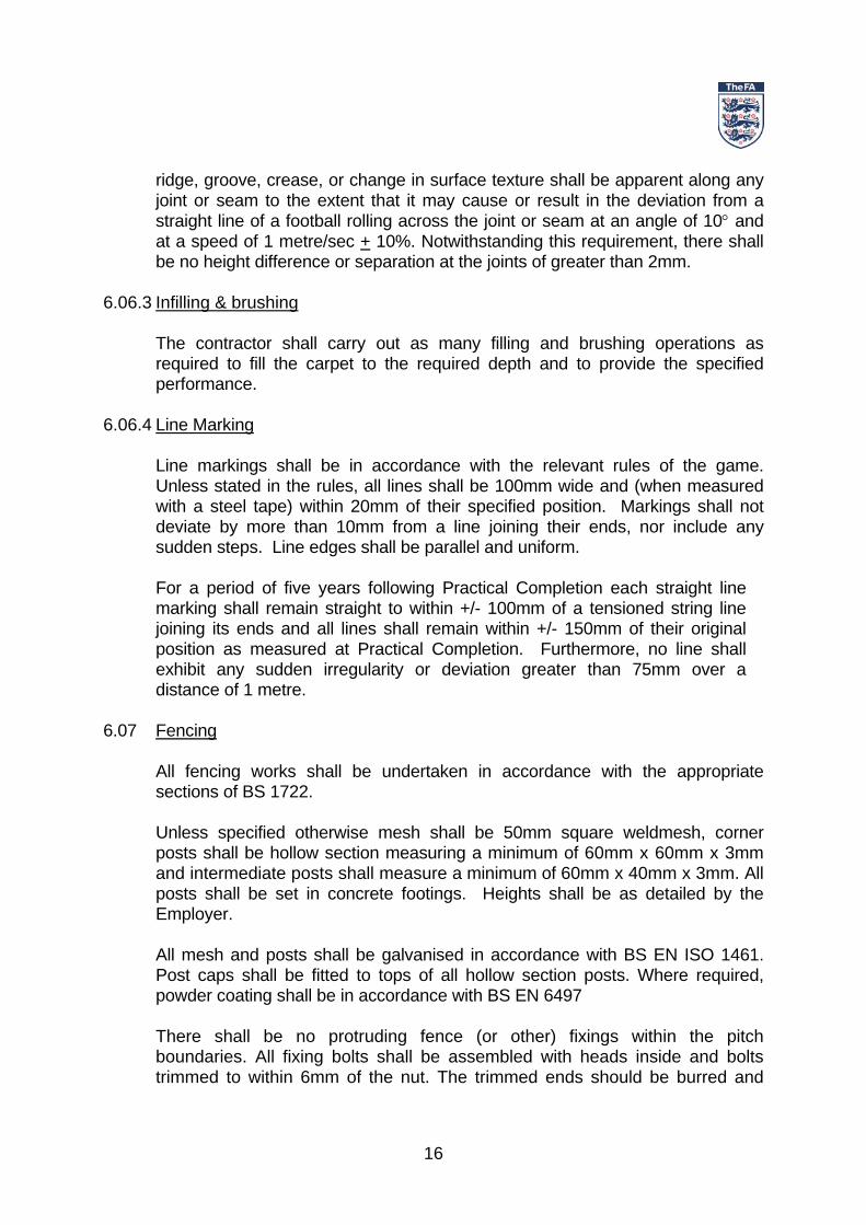
Appendix A Project Details – Site, Employer and Employer’s Agents
Site
1.1
Address
Employer Address
Tel Fax
1.2
E-mail Employer’s Agent / Contract Administrator
Address
Tel Fax
1.3
E-mail Pitch Consultant Address
Tel Fax
1.4
E-mail Electrical Engineer Address
Tel Fax
1.5
E-mail Planning Supervisor Address
Tel Fax
1.6
To b
e co
mpl
eted
in fu
ll be
fore
issu
ing
for t
ende
r

23
Appendix B Description of works
Guidance note The description of works should include:
• A full and detailed description of the works including a summary of the proposed sports to be played on the pitch (together with a prediction of the likely weekly usage)
• The type of surfacing, shockpad (if any) and sub-base required
• Details of any enabling works to be undertaken by others in advance of the
works
• Details of what is to happen to spoil arising from the works (taken off site, mounds, etc.)
• Details of the drainage outlet
• The type of fencing (height, mesh type and colour), gates (numbers, type
and height), rebound boards/mesh (type and colour), etc
• The required levels of floodlighting performance including details of any secondary level lighting to be provided for training and other sectional pitch use
• The location of the control and switchgear for the floodlighting system
• The location of an available power supply for the floodlighting system or
details of who is to provide an adequate supply
• Details of all small power, egress and amenity lighting and all control features to be provided as part of the floodlighting scheme
• Details of any landscaping works to be undertaken as part of the contract
• Details of any external maintenance access ways and footpaths etc to be
constructed by the contractor.
• Details of any site specific restrictions

24
Appendix C Schedule of drawings
Drawing number
Title Description
Topographical survey of existing site
Site location
Proposed layout & dimensions
Proposals for drainage outlet
Contractor’s access, working area and compound
Temporary fencing (type and locations)
Line markings (setting out and colours)
Add any other project or site specific drawings
To b
e co
mpl
eted
in fu
ll be
fore
be
ing
issu
ed fo
r ten
der

25
Appendix D
Employer’s Specific Conditions, Preliminaries & Form of Contract Guidance note: Appendix D should contain:
• The Employer’s specific conditions
• The Employer’s Preambles
• The Employer’s Preliminaries
• The Employer’s Form of Contract and Appendices to the Form of Contract
• The Employer’s specific conditions
• Any conditions of tendering or procurement stipulated by the Employer or
external funding partners

26
Appendix E
Planning Approval
Guidance note:
In order that the contractor is aware and may comply with all planning conditions
Appendix E should include a copy of the original planning application (including
all supporting information), the notification of planning approval and any
conditions attached.

27
Appendix F
Pre-tender Health & Safety Plan
Guidance note:
As required by the Construction (Design & Management Regulations) a pre-
tender health and safety plan should be prepared and issued as part of the
tender documentation.

28
Appendix G
Ground investigation report
Guidance note:
Appendix G should contain the ground investigation report commissioned by
the Employer prior to seeking tenders (see Guide to Artificial Grass Pitches for
Community Use, Part 2, Section 8)

29
Appendix H
Schedule of information to be included in Contractor’s Proposals
The Contractor shall supply the following information with their tender: • A fully detailed method statement, giving the methods and sequence of
construction operations. • Specifications for all proposed materials. • Drawings indicating the proposed construction, the anticipated finished levels
of the playing surface and surrounds, the arrangements for drainage works, together with anticipated invert levels, lines and depths of all ducts and cables and any proposed modifications of any existing services.
• An outline programme for the construction works in the form of a bar chart
showing the main sequence of the works. • Fencing design • Details of warranty being offered • An independent test report detailing the performance of the precise
construction being proposed and its ability to satisfy the FA’s Performance Standard for Outdoor Artificial Grass Pitches for Community Use
• Details of at least three pitches of similar construction, including date of
installation and reference contact • A computer plot showing the anticipated floodlight values of Horizontal
Illuminance over each playing area at each level of illuminance. • Computer plots of horizontal and vertical illuminance showing the predicted
floodlight light spillage of the proposed system extending at least 50m beyond the pitch perimeters.
• Specification and details of the make and types of floodlight equipment,
including details of the characteristics of the type(s) of lamp offered • The proposed locations and height of floodlight columns
• Details of the dimensions of the floodlight column bases and the calculations
on which these are based.

30
• The start-up and running power loadings (Kva) for the floodlight scheme
and the predicted running cost per hour.
• The floodlight manufacturer’s warranty
• Details of at least three pitches with similar lighting systems, including date of installation and reference contact
(Plus all other information required by the Employer, as listed)

31
Appendix I
Equipment to be supplied by contractor Sports equipment
Description Number
Required Supplier Supplier reference
Goals (full size)
Mini soccer goals
Small sided football goals
Corner flags
List all other sports equipment to be supplied by pitch contractor
Maintenance equipment
Description Number Required
Supplier Supplier reference
List all maintenance equipment to be supplied by pitch contractor

32
Appendix J
Form of Tender and Contract Sum analysis
FORM OF TENDER To: Name of Employer For: Construction of artificial grass football pitch at……………………………… From (Contractor):
……………………………………………………………………… Sirs, I/We having read the Conditions of contract and employer’s requirements
delivered to me/us and having examined all drawings referred to therein do hereby offer to execute and complete in accordance with the Conditions of Contract the whole of the Works described within …………….. weeks from the date of possession for the sum of:
£………………………………………………………….. (VAT exclusive) I/We agree that should obvious errors in pricing or errors in arithmetic be
discovered before acceptance of this offer in the Tender Sum Analysis submitted by me/us these errors will be corrected in accordance with Alternative 2 contained in Section 10 of the NJCC Code of Procedure for Tendering for Design and Build.
I/We undertake to enter into a formal contract in the form specified. I/We agree
that until this tender is incorporated in such a formal contract, executed under deed by the Employer, this tender together with your written acceptance thereof will constitute a binding contract between us.
I/We confirm that if our tender is accepted we will require a period of
…………………… weeks prior to works commencing on site. I/We further agree that this tender remains open for consideration for twelve
(12) weeks from the last day of submission of tenders. I/We note that you do not undertake to accept the lowest or any tender and that
the Contractors tendering do so free of charge.

33
I/We declare this tender to be a bona fide tender intended to be competitive and that I/We have not fixed or adjusted the amount of the tender by or under or in accordance with any agreement or arrangement with any other person.
I/We confirm that the Annual Renewal date of Insurance as supplied by me/us
and referred to in the Conditions of Contract is ……………………………….…………… We confirm that we have visited the site and made all necessary investigations
before submitting this tender.
Dated this …………… day of ………………………. 20……. For and on behalf of: ……………………………………………………………….. Signed:…………………………………………………………. Registered address: …………………………………………………………………………………………. ………………………………………………………………………………………….

34
Tender sum analysis The Contractor shall enter costs against those items specifically listed below.
Item
£ p
Contingency (normally set at between 5% and 10% of estimated cost)
Preliminaries & site establishment
Site strip and preparation of formation
Installation of sub-pitch drainage & outlet
Pitch edgings
Pitch sub-base (including geotextile)
Macadam courses, if applicable
Shockpad, if applicable
Artificial grass, filing and line markings
Spectator area, if applicable
Storage compounds, if applicable
Fencing & gates
Division nets, if applicable
Floodlight columns and local switchgear
Floodlight fittings
Floodlight power distribution cabling and connection
Floodlight system management
Power socket provision
Reinstatement & landscaping
Total carried forward
Exam
ple
To
be
com
plet
ed a
s ap
prop
riate
for a
ctua
l sch
eme

35
Total carried forward
Sports equipment (list)
Maintenance equipment (list)
Any items not specifically included above (list)
Total carried to form of tender
Exam
ple
To
be
com
plet
ed a
s ap
prop
riate
for a
ctua
l sc
hem
e
Value Added Tax The Contractor is set out below a provisional indication of the amount of Value
Added Tax the Employer will be called upon to pay under the VAT Agreement. £………………………………………………………………..

36
Extra-over costs (excluding VAT)
Item
£ p
Excavation and back filling of soft spots per m3
List all optional items to be priced by tenderers but not included in main
tender sum
Assignment of sub-contracting
The contractor is to state in the following schedule the names of all the sub-contractors that he will employ on the works and their stated trades.
Company Trade

37
Prepared for the Football Association by Centre for Sports Technology
Tel. +44 (0) 1629 58 33 66 Fax. +44 (0) 1629 58 33 77 http://www.cst-global.com/