Embed Size (px)
Citation preview

8/6/2019 Guide Right Product Catalog 2011
http://slidepdf.com/reader/full/guide-right-product-catalog-2011 1/29
by DéPlaqueGuide Right
2011 Product Catalog
www.deplaque.com • 1.800.314.0065
a precision implant planning,
correction and placement technique
™
8/6/2019 Guide Right Product Catalog 2011
http://slidepdf.com/reader/full/guide-right-product-catalog-2011 2/29
How to order
Order online at www.deplaque.com, or callDéPlaque customer service at
800-314-0065 (US)585-924-3190 (International)
between 9am and 4pm EST Monday throughFriday. Closed some holidays.
Orders may also be faxed to 585-924-3378.
Shipping information
All US orders are shipped via USPS prioritymail. Alternative carriers upon request. Inter-national orders will be shipped FedEx or UPS;
customs and taxes will be added to the order andbilled to the receiver.
Return policy
Customers may return unopened and undamagedDéPlaque product in its original packaging within 30days of date of invoice to be eligible for full credit or replacement. Customers must contact DePlaqueprior to a return to receive an RMA (customer returnnumber). A 15% restocking fee will be charged for returns without a customer return number. Allreturn inquiries should be sent to [email protected]. No credits, exchanges or refunds willbe provided on discontinued product or product witha shelf life of less than six months. Credit or refundfor returned items will be issued upon receipt andinspection of goods by DéPlaque.
Limitation of liability
Purchaser assumes all risks and liabilityresulting from the use of these products,
whether used separately or in combination with other products not sold by DéPlaque. DéPlaquerecommends completion of formal postgraduateimplant education and adherence to recommendedimplant procedures. U.S. law restricts the sale of medical devices to licensed or certied medical/dental professionals.
Trademark information
Guide RightTM is a trademark of DéPlaque, Inc.All rights reserved.
Product development updates
Product development updates can be viewed onour website: www.deplaque.com
DéPlaque
Guide RightTM is a doctor-developed, prosthetically generated precision implant template planningand correction system that can be made in the ofce or by a lab. The template enables dental profes-sionals to communicate the desired location of an implant placement by using radiopaque stainless steel
or ceramic guide sleeves to locate the exact position of the implant. Guide sleeves are captured in alight cured resin gel on a plaster cast, removed, and then indexed to the patient’s adjacent teeth. TheGuide RightTM technique requires a diagnostic wax-up, or set-up utilizing set-up disks to determine
the position and angle of the osteotomy sites. The fabricated template is placed in the patient’s mouthand a radiograph is taken to determine if the path of insertion is in conict with the adjacent teeth orother anatomic structures. If a conict exists, the components can be removed and the template can beremade using angled or offset guideposts that can be bent for your required application. Guide RightTM component parts work with 2D and 3D X-Rays, and all major implant systems and are reusable.
The Guide Right ™ Story
1-800-314-00651
What is Guide Right ™ ?
As with many beginner dental implant cases, Dr. Sean Meitner experienced less than desirableimplant placement often discovered in the post surgical x-ray. It wasn’t long before he made a tripto the hardware store to collect material to create a makeshift guide system to assist him in betterplacment. From his innovative discoveries he has designed and developed Guide Right™, a Universal PrecisionImplant Placement System that has resulted in signicantly more accurate implant placement.
®
8/6/2019 Guide Right Product Catalog 2011
http://slidepdf.com/reader/full/guide-right-product-catalog-2011 3/29
Guide RightTM Template Component Kits
Stainless ……………………………………………………………………………………… 3
Ceramic……………………………………………………………………………………… 5Magnetic Set ……………………………………………………………………………………… 6
Guide RightTM Components
Guide Posts ………………………………………………………………………… 7Guide Sleeves ………………………………………………………………………… 9Guide Sleeve Inserts ………………………………………………………………………… 11
Guide RightTM Accessories
Generation II Guide Post Bending Tool ………………………………… 13Protractor ………………………………………… 13Autoclavable Instrument Tray ………………………………………… 13Insert Removal Tool ………………………………………… 14Fabrication Insert ………………………………………… 14Depth Gauge/Direction Indicator ………………………………………… 14Setup Disks ………………………………………… 14
Drills ………………………………………………………………………………………………………………………… 16
Oral Hygiene
Interproximal Brushes …………………………………………………………………… 20Oral Hygiene Products …………………………………………………………………… 20
Educational
Use of the Bending Tool ………………………………………… 23-26Set-up Disk Technique ………………………………………… 19Universal Template Technique ………………………………………… 17-18Open Guide Sleeve/Magnetic Post Technique …………… 15Helpful Advice ………………………………………… 21Comparison Chart for Drill Size with Guide Sleeves ……………27-28
Index ……………………………………………………………………………………………………… 29
Table of Contents
2www.deplaque.com
8/6/2019 Guide Right Product Catalog 2011
http://slidepdf.com/reader/full/guide-right-product-catalog-2011 4/29
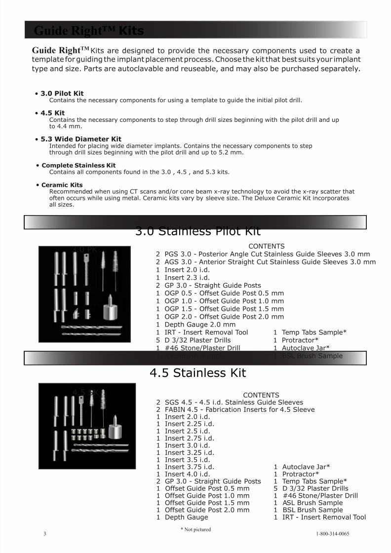
CONTENTS2 PGS 3.0 - Posterior Angle Cut Stainless Guide Sleeves 3.0 mm2 AGS 3.0 - Anterior Straight Cut Stainless Guide Sleeves 3.0 mm1 Insert 2.0 i.d.1 Insert 2.3 i.d.2 GP 3.0 - Straight Guide Posts1 OGP 0.5 - Offset Guide Post 0.5 mm1 OGP 1.0 - Offset Guide Post 1.0 mm1 OGP 1.5 - Offset Guide Post 1.5 mm1 OGP 2.0 - Offset Guide Post 2.0 mm1 Depth Gauge 2.0 mm1 IRT - Insert Removal Tool 1 Temp Tabs Sample*5 D 3/32 Plaster Drills 1 Protractor*1 #46 Stone/Plaster Drill 1 Autoclave Jar*1 ASL Brush Sample 1 BSL Brush Sample
CONTENTS2 SGS 4.5 - 4.5 i.d. Stainless Guide Sleeves2 FABIN 4.5 - Fabrication Inserts for 4.5 Sleeve1 Insert 2.0 i.d.1 Insert 2.25 i.d.1 Insert 2.5 i.d.1 Insert 2.75 i.d.1 Insert 3.0 i.d.1 Insert 3.25 i.d.1 Insert 3.5 i.d.1 Insert 3.75 i.d. 1 Autoclave Jar*1 Insert 4.0 i.d. 1 Protractor*
2 GP 3.0 - Straight Guide Posts 1 Temp Tabs Sample*1 Offset Guide Post 0.5 mm 5 D 3/32 Plaster Drills1 Offset Guide Post 1.0 mm 1 #46 Stone/Plaster Drill1 Offset Guide Post 1.5 mm 1 ASL Brush Sample1 Offset Guide Post 2.0 mm 1 BSL Brush Sample1 Depth Gauge 1 IRT - Insert Removal Tool
Guide Right™ Kits
3.0 Stainless Pilot Kit
4.5 Stainless Kit
• 3.0 Pilot KitContains the necessary components for using a template to guide the initial pilot drill.
• 4.5 KitContains the necessary components to step through drill sizes beginning with the pilot drill and upto 4.4 mm.
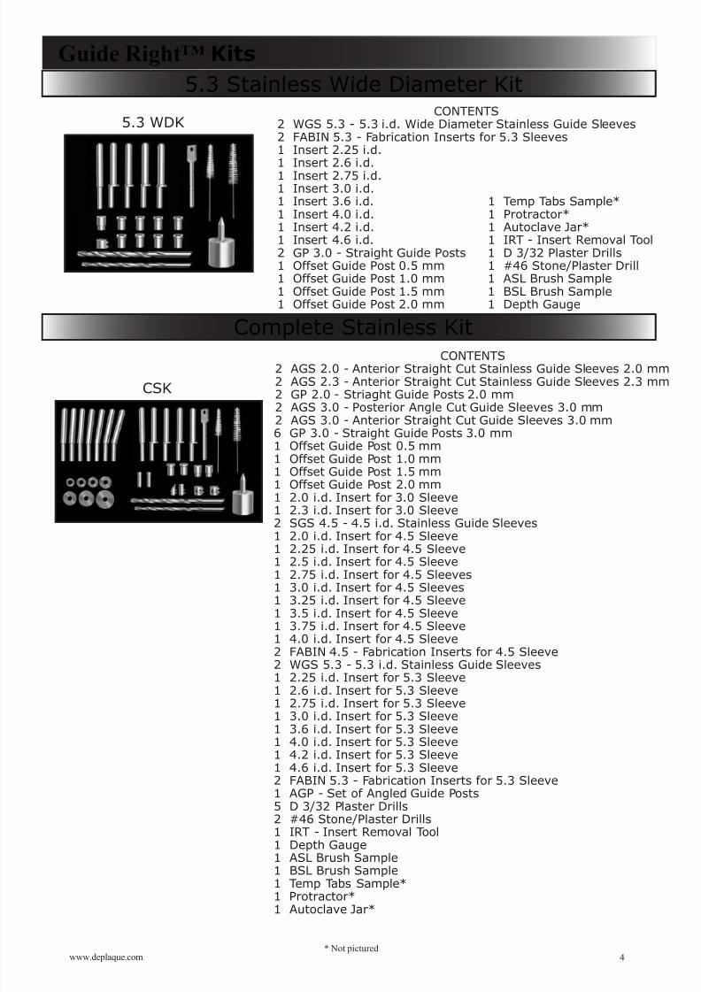
• 5.3 Wide Diameter Kit Intended for placing wide diameter implants. Contains the necessary components to stepthrough drill sizes beginning with the pilot drill and up to 5.2 mm.
• Complete Stainless KitContains all components found in the 3.0 , 4.5 , and 5.3 kits.
• Ceramic Kits
Recommended when using CT scans and/or cone beam x-ray technology to avoid the x-ray scatter thatoften occurs while using metal. Ceramic kits vary by sleeve size. The Deluxe Ceramic Kit incorporatesall sizes.
1-800-314-00653
Guide RightTM Kits are designed to provide the necessary components used to create a template for guiding the implant placement process. Choose the kit that best suits your implanttype and size. Parts are autoclavable and reuseable, and may also be purchased separately.
* Not pictured
3.0 PK
4.5 SK
8/6/2019 Guide Right Product Catalog 2011
http://slidepdf.com/reader/full/guide-right-product-catalog-2011 5/29
CONTENTS2 AGS 2.0 - Anterior Straight Cut Stainless Guide Sleeves 2.0 mm2 AGS 2.3 - Anterior Straight Cut Stainless Guide Sleeves 2.3 mm2 GP 2.0 - Striaght Guide Posts 2.0 mm2 AGS 3.0 - Posterior Angle Cut Guide Sleeves 3.0 mm2 AGS 3.0 - Anterior Straight Cut Guide Sleeves 3.0 mm6 GP 3.0 - Straight Guide Posts 3.0 mm1 Offset Guide Post 0.5 mm1 Offset Guide Post 1.0 mm1 Offset Guide Post 1.5 mm1 Offset Guide Post 2.0 mm1 2.0 i.d. Insert for 3.0 Sleeve1 2.3 i.d. Insert for 3.0 Sleeve
2 SGS 4.5 - 4.5 i.d. Stainless Guide Sleeves1 2.0 i.d. Insert for 4.5 Sleeve1 2.25 i.d. Insert for 4.5 Sleeve1 2.5 i.d. Insert for 4.5 Sleeve1 2.75 i.d. Insert for 4.5 Sleeves1 3.0 i.d. Insert for 4.5 Sleeves1 3.25 i.d. Insert for 4.5 Sleeve1 3.5 i.d. Insert for 4.5 Sleeve1 3.75 i.d. Insert for 4.5 Sleeve1 4.0 i.d. Insert for 4.5 Sleeve2 FABIN 4.5 - Fabrication Inserts for 4.5 Sleeve2 WGS 5.3 - 5.3 i.d. Stainless Guide Sleeves1 2.25 i.d. Insert for 5.3 Sleeve
1 2.6 i.d. Insert for 5.3 Sleeve1 2.75 i.d. Insert for 5.3 Sleeve1 3.0 i.d. Insert for 5.3 Sleeve1 3.6 i.d. Insert for 5.3 Sleeve1 4.0 i.d. Insert for 5.3 Sleeve1 4.2 i.d. Insert for 5.3 Sleeve1 4.6 i.d. Insert for 5.3 Sleeve2 FABIN 5.3 - Fabrication Inserts for 5.3 Sleeve1 AGP - Set of Angled Guide Posts5 D 3/32 Plaster Drills2 #46 Stone/Plaster Drills1 IRT - Insert Removal Tool1 Depth Gauge1 ASL Brush Sample
1 BSL Brush Sample1 Temp Tabs Sample*1 Protractor*1 Autoclave Jar*
CONTENTS2 WGS 5.3 - 5.3 i.d. Wide Diameter Stainless Guide Sleeves2 FABIN 5.3 - Fabrication Inserts for 5.3 Sleeves1 Insert 2.25 i.d.1 Insert 2.6 i.d.
1 Insert 2.75 i.d.1 Insert 3.0 i.d.1 Insert 3.6 i.d. 1 Temp Tabs Sample*1 Insert 4.0 i.d. 1 Protractor*1 Insert 4.2 i.d. 1 Autoclave Jar*1 Insert 4.6 i.d. 1 IRT - Insert Removal Tool2 GP 3.0 - Straight Guide Posts 1 D 3/32 Plaster Drills1 Offset Guide Post 0.5 mm 1 #46 Stone/Plaster Drill1 Offset Guide Post 1.0 mm 1 ASL Brush Sample1 Offset Guide Post 1.5 mm 1 BSL Brush Sample1 Offset Guide Post 2.0 mm 1 Depth Gauge
5.3 Stainless Wide Diameter Kit Guide Right™ Kits
Complete Stainless Kit
4www.deplaque.com* Not pictured
5.3 WDK
CSK
8/6/2019 Guide Right Product Catalog 2011
http://slidepdf.com/reader/full/guide-right-product-catalog-2011 6/29
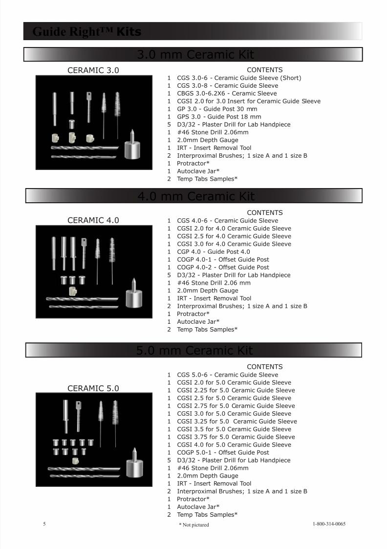
CONTENTS1 CGS 3.0-6 - Ceramic Guide Sleeve (Short)1 CGS 3.0-8 - Ceramic Guide Sleeve
1 CBGS 3.0-6.2X6 - Ceramic Sleeve1 CGSI 2.0 for 3.0 Insert for Ceramic Guide Sleeve1 GP 3.0 - Guide Post 30 mm1 GPS 3.0 - Guide Post 18 mm5 D3/32 - Plaster Drill for Lab Handpiece1 #46 Stone Drill 2.06mm1 2.0mm Depth Gauge1 IRT - Insert Removal Tool2 Interproximal Brushes; 1 size A and 1 size B1 Protractor*1 Autoclave Jar*2 Temp Tabs Samples*
CONTENTS1 CGS 4.0-6 - Ceramic Guide Sleeve1 CGSI 2.0 for 4.0 Ceramic Guide Sleeve1 CGSI 2.5 for 4.0 Ceramic Guide Sleeve1 CGSI 3.0 for 4.0 Ceramic Guide Sleeve1 CGP 4.0 - Guide Post 4.01 COGP 4.0-1 - Offset Guide Post1 COGP 4.0-2 - Offset Guide Post5 D3/32 - Plaster Drill for Lab Handpiece1 #46 Stone Drill 2.06 mm
1 2.0mm Depth Gauge1 IRT - Insert Removal Tool2 Interproximal Brushes; 1 size A and 1 size B1 Protractor*1 Autoclave Jar*2 Temp Tabs Samples*
CONTENTS1 CGS 5.0-6 - Ceramic Guide Sleeve
1 CGSI 2.0 for 5.0 Ceramic Guide Sleeve1 CGSI 2.25 for 5.0 Ceramic Guide Sleeve1 CGSI 2.5 for 5.0 Ceramic Guide Sleeve1 CGSI 2.75 for 5.0 Ceramic Guide Sleeve1 CGSI 3.0 for 5.0 Ceramic Guide Sleeve1 CGSI 3.25 for 5.0 Ceramic Guide Sleeve1 CGSI 3.5 for 5.0 Ceramic Guide Sleeve1 CGSI 3.75 for 5.0 Ceramic Guide Sleeve1 CGSI 4.0 for 5.0 Ceramic Guide Sleeve1 COGP 5.0-1 - Offset Guide Post5 D3/32 - Plaster Drill for Lab Handpiece1 #46 Stone Drill 2.06mm1 2.0mm Depth Gauge
1 IRT - Insert Removal Tool2 Interproximal Brushes; 1 size A and 1 size B1 Protractor*1 Autoclave Jar*2 Temp Tabs Samples*
Guide Right™ Kits
3.0 mm Ceramic Kit
4.0 mm Ceramic Kit
5.0 mm Ceramic Kit
1-800-314-00655 * Not pictured
CERAMIC 3.0
CERAMIC 4.0
CERAMIC 5.0
8/6/2019 Guide Right Product Catalog 2011
http://slidepdf.com/reader/full/guide-right-product-catalog-2011 7/29
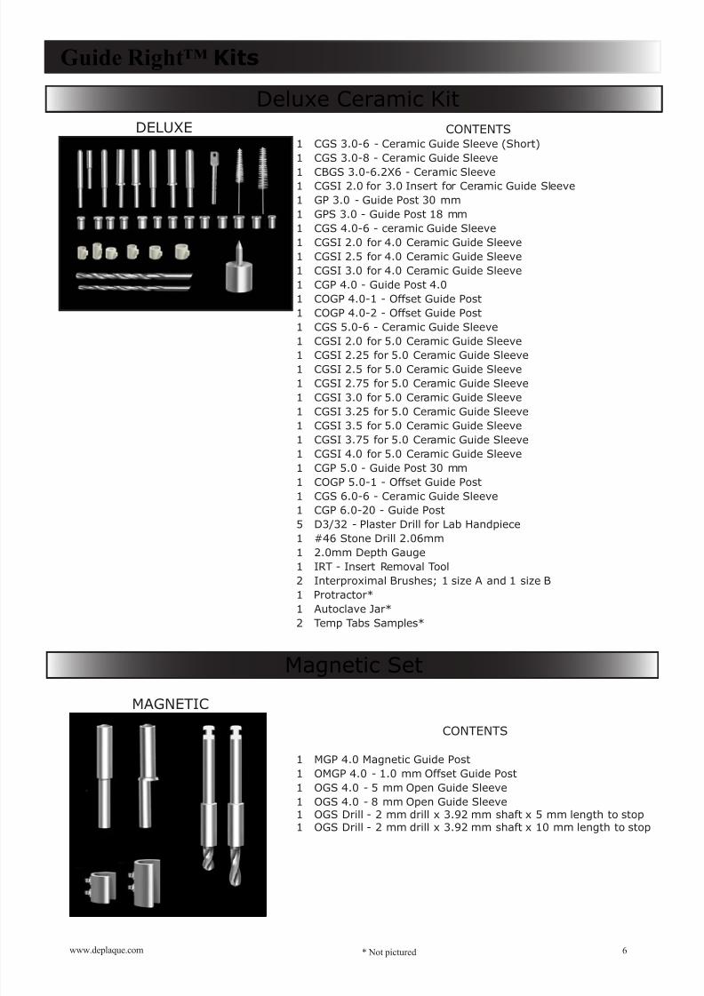
CONTENTS1 CGS 3.0-6 - Ceramic Guide Sleeve (Short)1 CGS 3.0-8 - Ceramic Guide Sleeve
1 CBGS 3.0-6.2X6 - Ceramic Sleeve1 CGSI 2.0 for 3.0 Insert for Ceramic Guide Sleeve
1 GP 3.0 - Guide Post 30 mm
1 GPS 3.0 - Guide Post 18 mm1 CGS 4.0-6 - ceramic Guide Sleeve1 CGSI 2.0 for 4.0 Ceramic Guide Sleeve1 CGSI 2.5 for 4.0 Ceramic Guide Sleeve1 CGSI 3.0 for 4.0 Ceramic Guide Sleeve1 CGP 4.0 - Guide Post 4.01 COGP 4.0-1 - Offset Guide Post1 COGP 4.0-2 - Offset Guide Post1 CGS 5.0-6 - Ceramic Guide Sleeve1 CGSI 2.0 for 5.0 Ceramic Guide Sleeve1 CGSI 2.25 for 5.0 Ceramic Guide Sleeve1 CGSI 2.5 for 5.0 Ceramic Guide Sleeve1 CGSI 2.75 for 5.0 Ceramic Guide Sleeve1 CGSI 3.0 for 5.0 Ceramic Guide Sleeve1 CGSI 3.25 for 5.0 Ceramic Guide Sleeve1 CGSI 3.5 for 5.0 Ceramic Guide Sleeve1 CGSI 3.75 for 5.0 Ceramic Guide Sleeve1 CGSI 4.0 for 5.0 Ceramic Guide Sleeve1 CGP 5.0 - Guide Post 30 mm1 COGP 5.0-1 - Offset Guide Post1 CGS 6.0-6 - Ceramic Guide Sleeve1 CGP 6.0-20 - Guide Post
5 D3/32 - Plaster Drill for Lab Handpiece1 #46 Stone Drill 2.06mm1 2.0mm Depth Gauge1 IRT - Insert Removal Tool2 Interproximal Brushes; 1 size A and 1 size B1 Protractor*1 Autoclave Jar*2 Temp Tabs Samples*
Guide Right™ Kits
Deluxe Ceramic Kit
CONTENTS
1 MGP 4.0 Magnetic Guide Post1 OMGP 4.0 - 1.0 mm Offset Guide Post1 OGS 4.0 - 5 mm Open Guide Sleeve1 OGS 4.0 - 8 mm Open Guide Sleeve1 OGS Drill - 2 mm drill x 3.92 mm shaft x 5 mm length to stop1 OGS Drill - 2 mm drill x 3.92 mm shaft x 10 mm length to stop
6www.deplaque.com
Magnetic Set
* Not pictured
DELUXE
MAGNETIC
8/6/2019 Guide Right Product Catalog 2011
http://slidepdf.com/reader/full/guide-right-product-catalog-2011 8/29
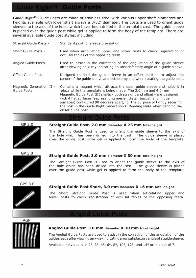
Straight Guide Post Short, 3.0 mm diameter X 16 mm total height
The Short Straight Guide Post is used when articulating upper andlower casts to check registration of occlusal tables of the opposing teeth.
Straight Guide Post, 3.0 mm diameter X 30 mm total height
The Straight Guide Post is used to orient the guide sleeve to the axis of the hole which has been drilled into the cast. The guide sleeve is placedover the guide post while gel is applied to form the body of the template.
Angled Guide Post 3.0 mm diameter X 30 mm total height
The Angled Guide Posts are used to assist in the correction of the angulation of theguide sleeve after viewing an x-ray indicating an unsatisfactory angle of a guide sleeve.
Available individually in 2°, 3°, 4°, 6°, 8°, 10°, 12°, and 14° or in a set of 7.
Guide Right™ Guide Posts
Straight Guide Posts
GP 3.0
Angled Guide Posts
Guide RightTM Guide Posts are made of stainless steel with various upper shaft diameters andheights available with lower shaft always a 3/32” diameter. The posts are used to orient guidesleeves to the axis of the holes which have been drilled in the template cast. The guide sleeveis placed over the guide post while gel is applied to form the body of the template. There areseveral available guide post styles, including:
Straight Guide Posts - Standard post for sleeve orientation.
Short Guide Posts - Used when articulating upper and lower casts to check registration of occlusal tables of the opposing teeth.
Angled Guide Posts - Used to assist in the correction of the angulation of the guide sleeveafter viewing an x-ray indicating an unsatisfactory angle of a guide sleeve.
Offset Guide Posts - Designed to hold the guide sleeve in an offset position to adjust thecenter of the guide sleeve and osteotomy site when rotating the guide post.
Magnetic Generation II - Contains a magnet which attracts the open guide sleeve and holds it inGuide Posts place while the template is being made. The 3.0 mm and 4.0 mm
Magnetic Guide Post GII shafts - both straight and offset - are designed
with 4 at surfaces (representing mesial, distal, buccal, and lingualsurfaces) congured 90 degrees apart, for the purpose of tightly securingthe post in the Guide Right Generation II Bending Plate when bending theoffset guide post.
GPS 3.0
AGP
1-800-314-00657
Straight Guide Post, 2.0 mm diameter X 25 mm total height
The Straight Guide Post is used to orient the guide sleeve to the axis of the hole which has been drilled into the cast. The guide sleeve is placedover the guide post while gel is applied to form the body of the template.
GP 2.0
8/6/2019 Guide Right Product Catalog 2011
http://slidepdf.com/reader/full/guide-right-product-catalog-2011 9/29
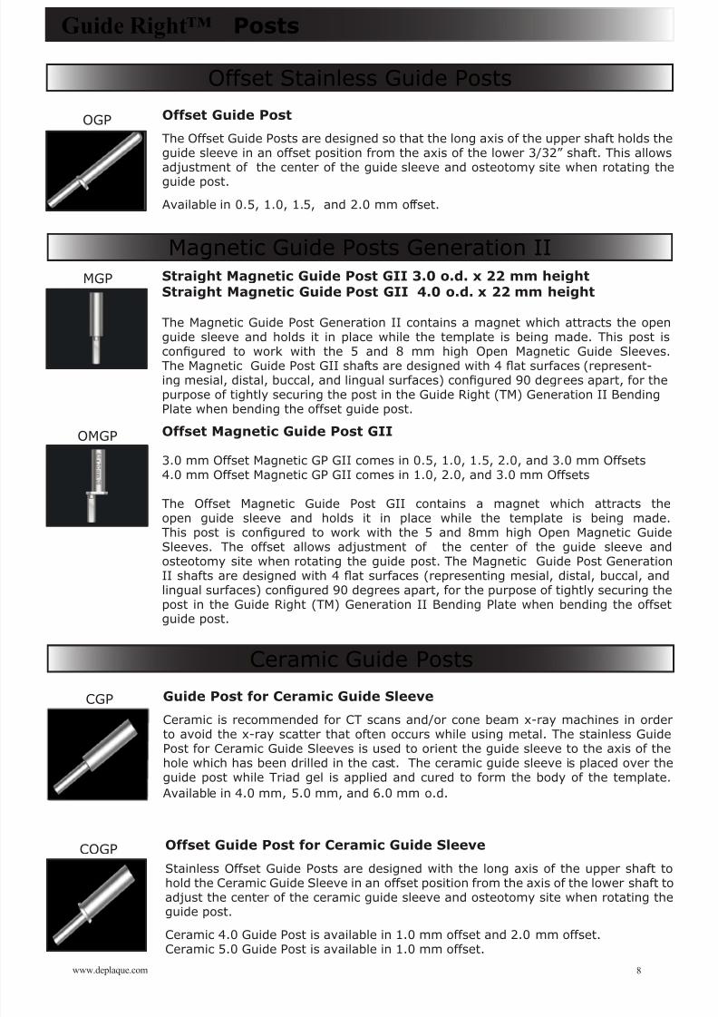
Straight Magnetic Guide Post GII 3.0 o.d. x 22 mm heightStraight Magnetic Guide Post GII 4.0 o.d. x 22 mm height
The Magnetic Guide Post Generation II contains a magnet which attracts the openguide sleeve and holds it in place while the template is being made. This post is
congured to work with the 5 and 8 mm high Open Magnetic Guide Sleeves.The Magnetic Guide Post GII shafts are designed with 4 at surfaces (represent-ing mesial, distal, buccal, and lingual surfaces) congured 90 degrees apart, for thepurpose of tightly securing the post in the Guide Right (TM) Generation II BendingPlate when bending the offset guide post.
Offset Magnetic Guide Post GII
3.0 mm Offset Magnetic GP GII comes in 0.5, 1.0, 1.5, 2.0, and 3.0 mm Offsets4.0 mm Offset Magnetic GP GII comes in 1.0, 2.0, and 3.0 mm Offsets
The Offset Magnetic Guide Post GII contains a magnet which attracts theopen guide sleeve and holds it in place while the template is being made.
This post is congured to work with the 5 and 8mm high Open Magnetic GuideSleeves. The offset allows adjustment of the center of the guide sleeve and osteotomy site when rotating the guide post. The Magnetic Guide Post GenerationII shafts are designed with 4 at surfaces (representing mesial, distal, buccal, andlingual surfaces) congured 90 degrees apart, for the purpose of tightly securing thepost in the Guide Right (TM) Generation II Bending Plate when bending the offsetguide post.
Offset Stainless Guide Posts
Offset Guide Post
The Offset Guide Posts are designed so that the long axis of the upper shaft holds theguide sleeve in an offset position from the axis of the lower 3/32” shaft. This allowsadjustment of the center of the guide sleeve and osteotomy site when rotating theguide post.
Available in 0.5, 1.0, 1.5, and 2.0 mm offset.
Magnetic Guide Posts Generation II
Guide Right™ Posts
Ceramic Guide Posts
Guide Post for Ceramic Guide Sleeve
Ceramic is recommended for CT scans and/or cone beam x-ray machines in orderto avoid the x-ray scatter that often occurs while using metal. The stainless GuidePost for Ceramic Guide Sleeves is used to orient the guide sleeve to the axis of thehole which has been drilled in the cast. The ceramic guide sleeve is placed over theguide post while Triad gel is applied and cured to form the body of the template.Available in 4.0 mm, 5.0 mm, and 6.0 mm o.d.
Offset Guide Post for Ceramic Guide Sleeve
Stainless Offset Guide Posts are designed with the long axis of the upper shaft tohold the Ceramic Guide Sleeve in an offset position from the axis of the lower shaft toadjust the center of the ceramic guide sleeve and osteotomy site when rotating theguide post.
Ceramic 4.0 Guide Post is available in 1.0 mm offset and 2.0 mm offset.Ceramic 5.0 Guide Post is available in 1.0 mm offset.
OGP
MGP
OMGP
CGP
COGP
8www.deplaque.com
8/6/2019 Guide Right Product Catalog 2011
http://slidepdf.com/reader/full/guide-right-product-catalog-2011 10/29
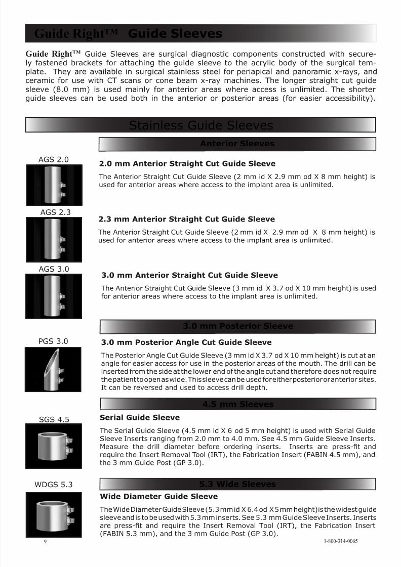
Guide RightTM Guide Sleeves are surgical diagnostic components constructed with secure-ly fastened brackets for attaching the guide sleeve to the acrylic body of the surgical tem-plate. They are available in surgical stainless steel for periapical and panoramic x-rays, andceramic for use with CT scans or cone beam x-ray machines. The longer straight cut guidesleeve (8.0 mm) is used mainly for anterior areas where access is unlimited. The shorter
guide sleeves can be used both in the anterior or posterior areas (for easier accessibility).
Guide Right™ Guide Sleeves
3.0 mm Anterior Straight Cut Guide Sleeve
The Anterior Straight Cut Guide Sleeve (3 mm id X 3.7 od X 10 mm height) is used
for anterior areas where access to the implant area is unlimited.
3.0 mm Posterior Angle Cut Guide Sleeve
The Posterior Angle Cut Guide Sleeve (3 mm id X 3.7 od X 10 mm height) is cut at anangle for easier access for use in the posterior areas of the mouth. The drill can beinserted from the side at the lower end of the angle cut and therefore does not requirethe patient to open as wide. This sleeve can be used for either posterior or anterior sites.It can be reversed and used to access drill depth.
Serial Guide Sleeve
The Serial Guide Sleeve (4.5 mm id X 6 od 5 mm height) is used with Serial GuideSleeve Inserts ranging from 2.0 mm to 4.0 mm. See 4.5 mm Guide Sleeve Inserts.Measure the drill diameter before ordering inserts. Inserts are press-t and require the Insert Removal Tool (IRT), the Fabrication Insert (FABIN 4.5 mm), andthe 3 mm Guide Post (GP 3.0).
Wide Diameter Guide Sleeve
The Wide Diameter Guide Sleeve (5.3 mm id X 6.4 od X 5 mm height) is the widest guidesleeve and is to be used with 5.3 mm inserts. See 5.3 mm Guide Sleeve Inserts. Insertsare press-t and require the Insert Removal Tool (IRT), the Fabrication Insert(FABIN 5.3 mm), and the 3 mm Guide Post (GP 3.0).
Stainless Guide Sleeves
AGS 2.0
PGS 3.0
SGS 4.5
WDGS 5.3
AGS 3.0
2.0 mm Anterior Straight Cut Guide Sleeve
The Anterior Straight Cut Guide Sleeve (2 mm id X 2.9 mm od X 8 mm height) isused for anterior areas where access to the implant area is unlimited.
AGS 2.32.3 mm Anterior Straight Cut Guide Sleeve
The Anterior Straight Cut Guide Sleeve (2 mm id X 2.9 mm od X 8 mm height) isused for anterior areas where access to the implant area is unlimited.
1-800-314-00659
Anterior Sleeves
3.0 mm Posterior Sleeve
4.5 mm Sleeves
5.3 Wide Sleeves
8/6/2019 Guide Right Product Catalog 2011
http://slidepdf.com/reader/full/guide-right-product-catalog-2011 11/29
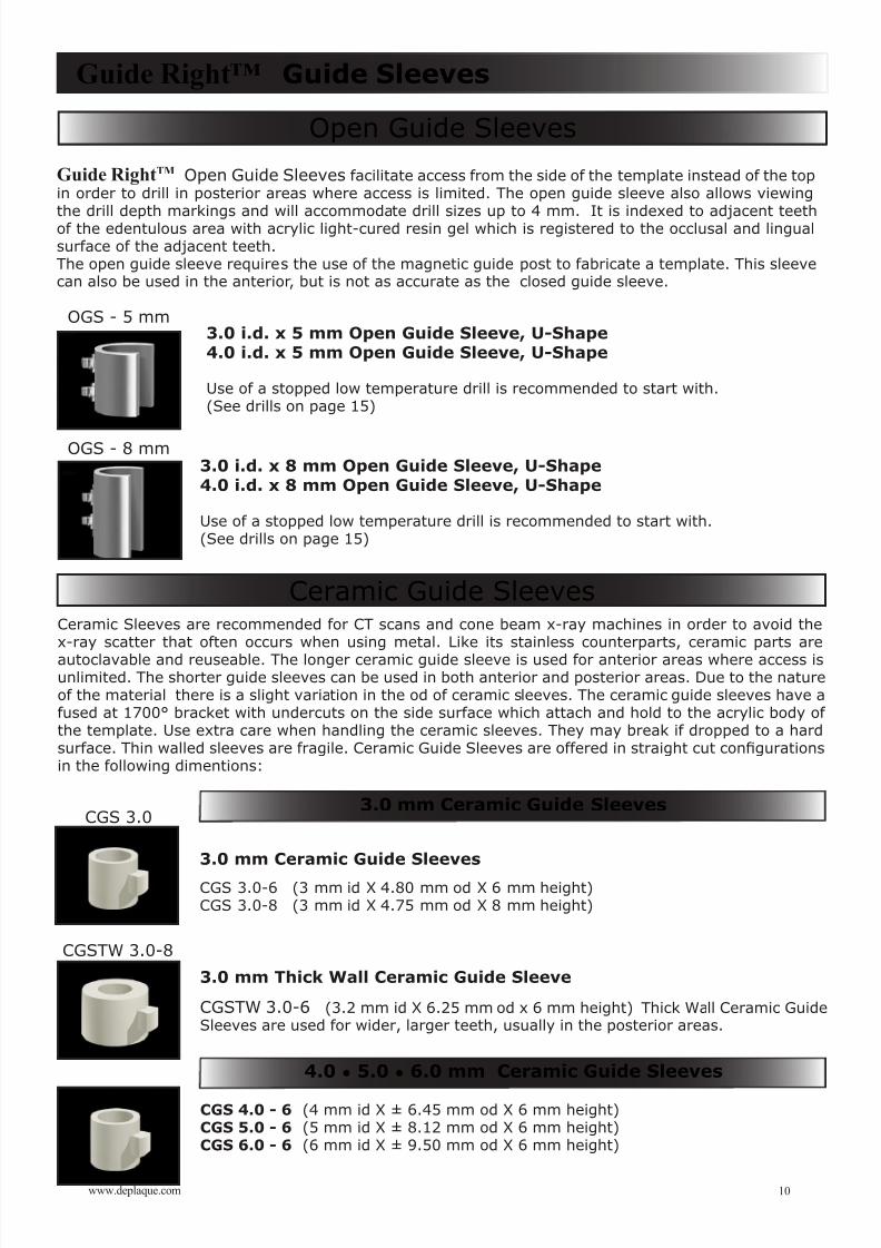
Guide RightTM Open Guide Sleeves facilitate access from the side of the template instead of the topin order to drill in posterior areas where access is limited. The open guide sleeve also allows viewing
the drill depth markings and will accommodate drill sizes up to 4 mm. It is indexed to adjacent teethof the edentulous area with acrylic light-cured resin gel which is registered to the occlusal and lingualsurface of the adjacent teeth.The open guide sleeve requires the use of the magnetic guide post to fabricate a template. This sleevecan also be used in the anterior, but is not as accurate as the closed guide sleeve.
3.0 i.d. x 8 mm Open Guide Sleeve, U-Shape4.0 i.d. x 8 mm Open Guide Sleeve, U-Shape
Use of a stopped low temperature drill is recommended to start with.(See drills on page 15)
3.0 mm Ceramic Guide Sleeves
CGS 3.0-6 (3 mm id X 4.80 mm od X 6 mm height)CGS 3.0-8 (3 mm id X 4.75 mm od X 8 mm height)
3.0 mm Thick Wall Ceramic Guide Sleeve
CGSTW 3.0-6 (3.2 mm id X 6.25 mm od x 6 mm height) Thick Wall Ceramic GuideSleeves are used for wider, larger teeth, usually in the posterior areas.
Guide Right™ Guide Sleeves
Open Guide Sleeves
Ceramic Guide Sleeves
CGSTW 3.0-8
CGS 3.0
OGS - 8 mm
OGS - 5 mm
10www.deplaque.com
Ceramic Sleeves are recommended for CT scans and cone beam x-ray machines in order to avoid thex-ray scatter that often occurs when using metal. Like its stainless counterparts, ceramic parts are
autoclavable and reuseable. The longer ceramic guide sleeve is used for anterior areas where access isunlimited. The shorter guide sleeves can be used in both anterior and posterior areas. Due to the natureof the material there is a slight variation in the od of ceramic sleeves. The ceramic guide sleeves have afused at 1700° bracket with undercuts on the side surface which attach and hold to the acrylic body of the template. Use extra care when handling the ceramic sleeves. They may break if dropped to a hardsurface. Thin walled sleeves are fragile. Ceramic Guide Sleeves are offered in straight cut congurationsin the following dimentions:
3.0 mm Ceramic Guide Sleeves
4.0 • 5.0 • 6.0 mm Ceramic Guide Sleeves
3.0 i.d. x 5 mm Open Guide Sleeve, U-Shape4.0 i.d. x 5 mm Open Guide Sleeve, U-Shape
Use of a stopped low temperature drill is recommended to start with.(See drills on page 15)
CGS 4.0 - 6 (4 mm id X ± 6.45 mm od X 6 mm height)CGS 5.0 - 6 (5 mm id X ± 8.12 mm od X 6 mm height)CGS 6.0 - 6 (6 mm id X ± 9.50 mm od X 6 mm height)
8/6/2019 Guide Right Product Catalog 2011
http://slidepdf.com/reader/full/guide-right-product-catalog-2011 12/29
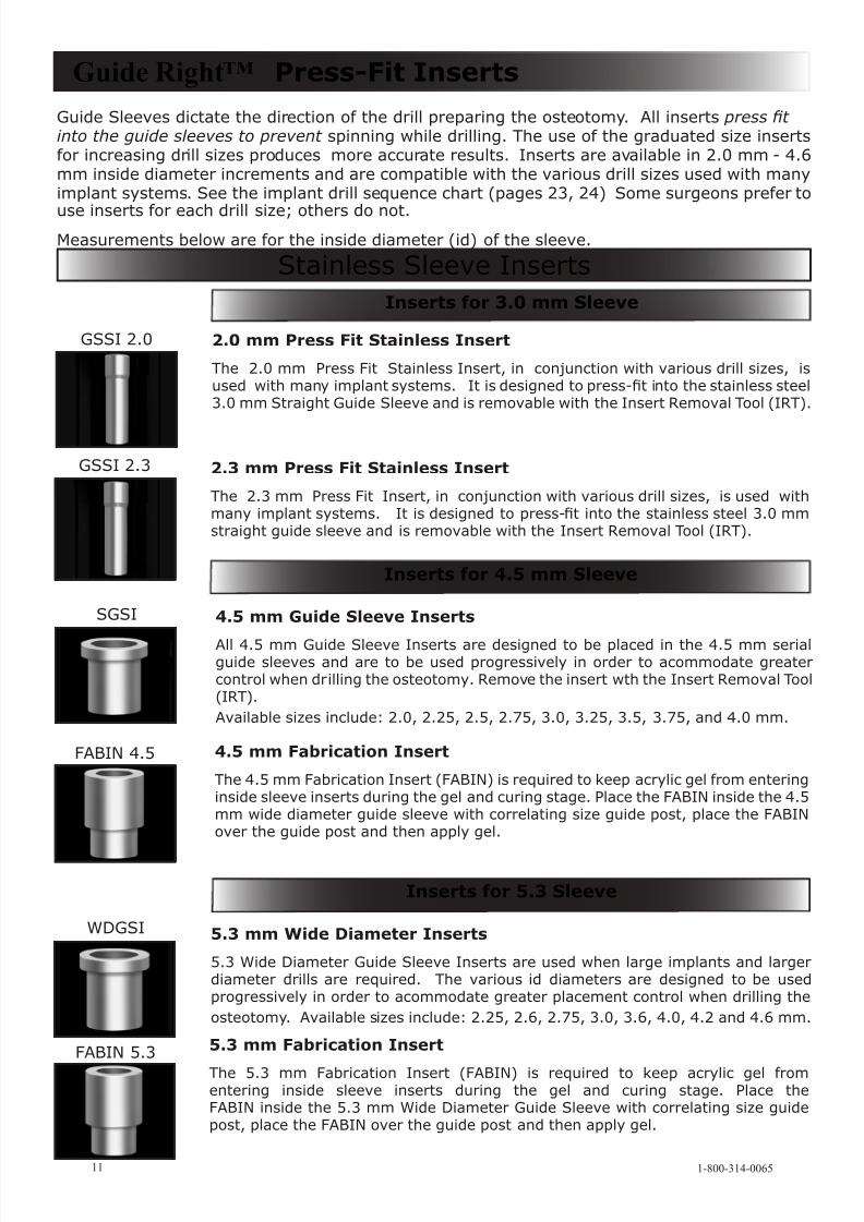
Guide Sleeves dictate the direction of the drill preparing the osteotomy. All inserts press t into the guide sleeves to prevent spinning while drilling. The use of the graduated size insertsfor increasing drill sizes produces more accurate results. Inserts are available in 2.0 mm - 4.6mm inside diameter increments and are compatible with the various drill sizes used with manyimplant systems. See the implant drill sequence chart (pages 23, 24) Some surgeons prefer to
use inserts for each drill size; others do not.Measurements below are for the inside diameter (id) of the sleeve.
2.0 mm Press Fit Stainless Insert
The 2.0 mm Press Fit Stainless Insert, in conjunction with various drill sizes, isused with many implant systems. It is designed to press-t into the stainless steel3.0 mm Straight Guide Sleeve and is removable with the Insert Removal Tool (IRT).
4.5 mm Guide Sleeve Inserts
All 4.5 mm Guide Sleeve Inserts are designed to be placed in the 4.5 mm serialguide sleeves and are to be used progressively in order to acommodate greatercontrol when drilling the osteotomy. Remove the insert wth the Insert Removal Tool(IRT).Available sizes include: 2.0, 2.25, 2.5, 2.75, 3.0, 3.25, 3.5, 3.75, and 4.0 mm.
4.5 mm Fabrication Insert
The 4.5 mm Fabrication Insert (FABIN) is required to keep acrylic gel from enteringinside sleeve inserts during the gel and curing stage. Place the FABIN inside the 4.5mm wide diameter guide sleeve with correlating size guide post, place the FABINover the guide post and then apply gel.
5.3 mm Wide Diameter Inserts
5.3 Wide Diameter Guide Sleeve Inserts are used when large implants and largerdiameter drills are required. The various id diameters are designed to be usedprogressively in order to acommodate greater placement control when drilling theosteotomy. Available sizes include: 2.25, 2.6, 2.75, 3.0, 3.6, 4.0, 4.2 and 4.6 mm.
5.3 mm Fabrication Insert
The 5.3 mm Fabrication Insert (FABIN) is required to keep acrylic gel fromentering inside sleeve inserts during the gel and curing stage. Place theFABIN inside the 5.3 mm Wide Diameter Guide Sleeve with correlating size guidepost, place the FABIN over the guide post and then apply gel.
Guide Right™ Press-Fit Inserts
GSSI 2.0
SGSI
FABIN 4.5
WDGSI
FABIN 5.3
Stainless Sleeve Inserts
1-800-314-006511
Inserts for 3.0 mm Sleeve
Inserts for 5.3 Sleeve
GSSI 2.3 2.3 mm Press Fit Stainless Insert
The 2.3 mm Press Fit Insert, in conjunction with various drill sizes, is used withmany implant systems. It is designed to press-t into the stainless steel 3.0 mmstraight guide sleeve and is removable with the Insert Removal Tool (IRT).
Inserts for 4.5 mm Sleeve
8/6/2019 Guide Right Product Catalog 2011
http://slidepdf.com/reader/full/guide-right-product-catalog-2011 13/29
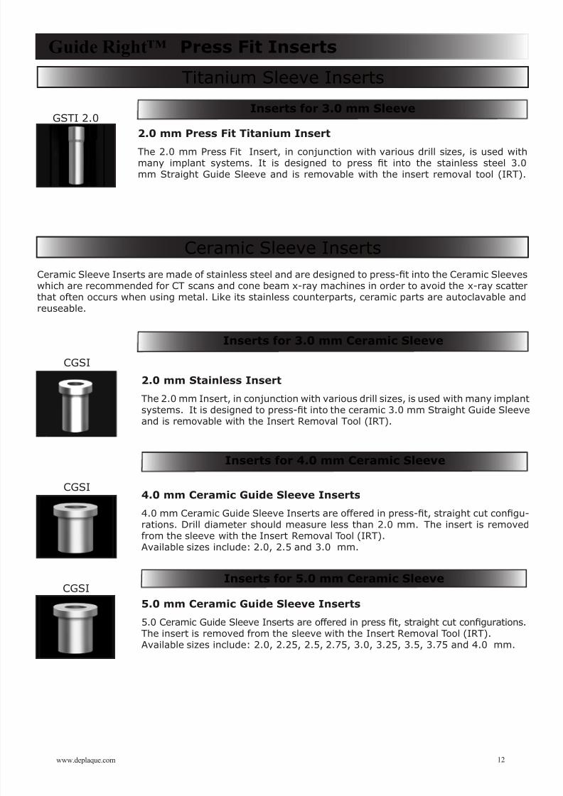
2.0 mm Press Fit Titanium Insert
The 2.0 mm Press Fit Insert, in conjunction with various drill sizes, is used withmany implant systems. It is designed to press t into the stainless steel 3.0mm Straight Guide Sleeve and is removable with the insert removal tool (IRT).
Titanium Sleeve Inserts
Ceramic Sleeve Inserts
Guide Right™ Press Fit Inserts
CGSI
CGSI
GSTI 2.0
4.0 mm Ceramic Guide Sleeve Inserts
4.0 mm Ceramic Guide Sleeve Inserts are offered in press-t, straight cut congu-rations. Drill diameter should measure less than 2.0 mm. The insert is removedfrom the sleeve with the Insert Removal Tool (IRT).Available sizes include: 2.0, 2.5 and 3.0 mm.
5.0 mm Ceramic Guide Sleeve Inserts
5.0 Ceramic Guide Sleeve Inserts are offered in press t, straight cut congurations.The insert is removed from the sleeve with the Insert Removal Tool (IRT).Available sizes include: 2.0, 2.25, 2.5, 2.75, 3.0, 3.25, 3.5, 3.75 and 4.0 mm.
CGSI
12www.deplaque.com
Inserts for 3.0 mm Sleeve
Inserts for 3.0 mm Ceramic Sleeve
Inserts for 4.0 mm Ceramic Sleeve
Ceramic Sleeve Inserts are made of stainless steel and are designed to press-t into the Ceramic Sleeveswhich are recommended for CT scans and cone beam x-ray machines in order to avoid the x-ray scatterthat often occurs when using metal. Like its stainless counterparts, ceramic parts are autoclavable andreuseable.
2.0 mm Stainless Insert
The 2.0 mm Insert, in conjunction with various drill sizes, is used with many implantsystems. It is designed to press-t into the ceramic 3.0 mm Straight Guide Sleeve
and is removable with the Insert Removal Tool (IRT).
Inserts for 5.0 mm Ceramic Sleeve
8/6/2019 Guide Right Product Catalog 2011
http://slidepdf.com/reader/full/guide-right-product-catalog-2011 14/29
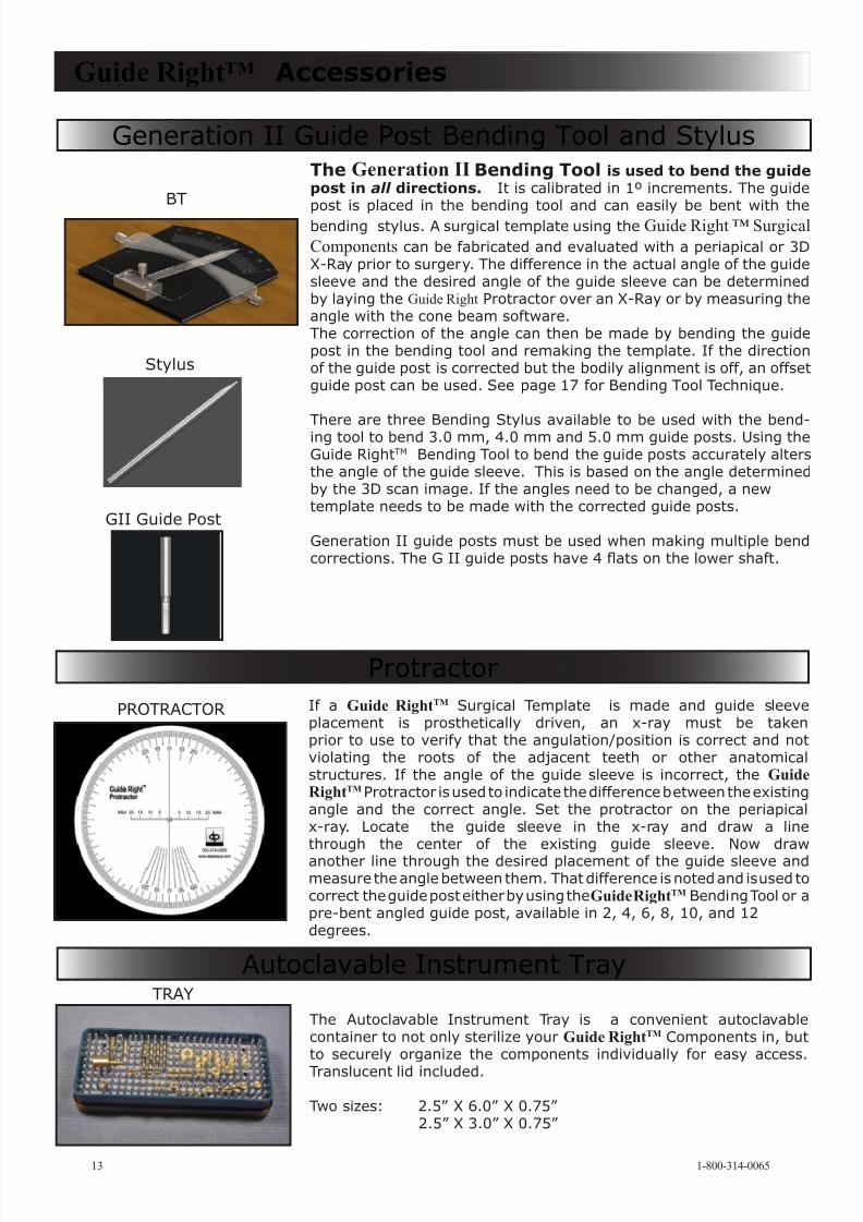
The Generation II Bending Tool is used to bend the guidepost in all directions. It is calibrated in 1º increments. The guidepost is placed in the bending tool and can easily be bent with thebending stylus. A surgical template using the Guide Right ™ Surgical
Components can be fabricated and evaluated with a periapical or 3DX-Ray prior to surgery. The difference in the actual angle of the guidesleeve and the desired angle of the guide sleeve can be determinedby laying the Guide Right Protractor over an X-Ray or by measuring theangle with the cone beam software.The correction of the angle can then be made by bending the guidepost in the bending tool and remaking the template. If the directionof the guide post is corrected but the bodily alignment is off, an offsetguide post can be used. See page 17 for Bending Tool Technique.
There are three Bending Stylus available to be used with the bend-ing tool to bend 3.0 mm, 4.0 mm and 5.0 mm guide posts. Using theGuide RightTM Bending Tool to bend the guide posts accurately altersthe angle of the guide sleeve. This is based on the angle determinedby the 3D scan image. If the angles need to be changed, a newtemplate needs to be made with the corrected guide posts.
Generation II guide posts must be used when making multiple bendcorrections. The G II guide posts have 4 ats on the lower shaft.
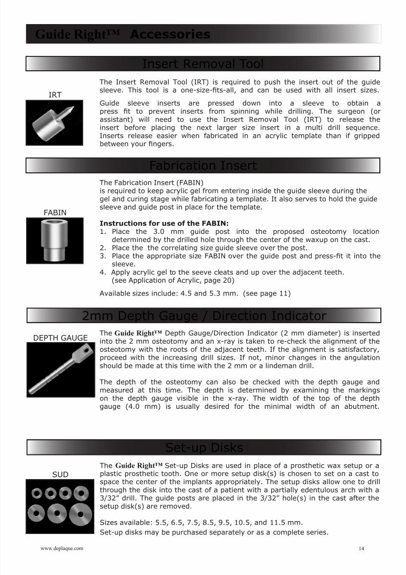
If a Guide RightTM Surgical Template is made and guide sleeveplacement is prosthetically driven, an x-ray must be takenprior to use to verify that the angulation/position is correct and notviolating the roots of the adjacent teeth or other anatomicalstructures. If the angle of the guide sleeve is incorrect, the GuideRightTM Protractor is used to indicate the difference between the existingangle and the correct angle. Set the protractor on the periapical x-ray. Locate the guide sleeve in the x-ray and draw a linethrough the center of the existing guide sleeve. Now draw
another line through the desired placement of the guide sleeve andmeasure the angle between them. That difference is noted and is used tocorrect the guide post either by using theGuide RightTM Bending Tool or apre-bent angled guide post, available in 2, 4, 6, 8, 10, and 12degrees.
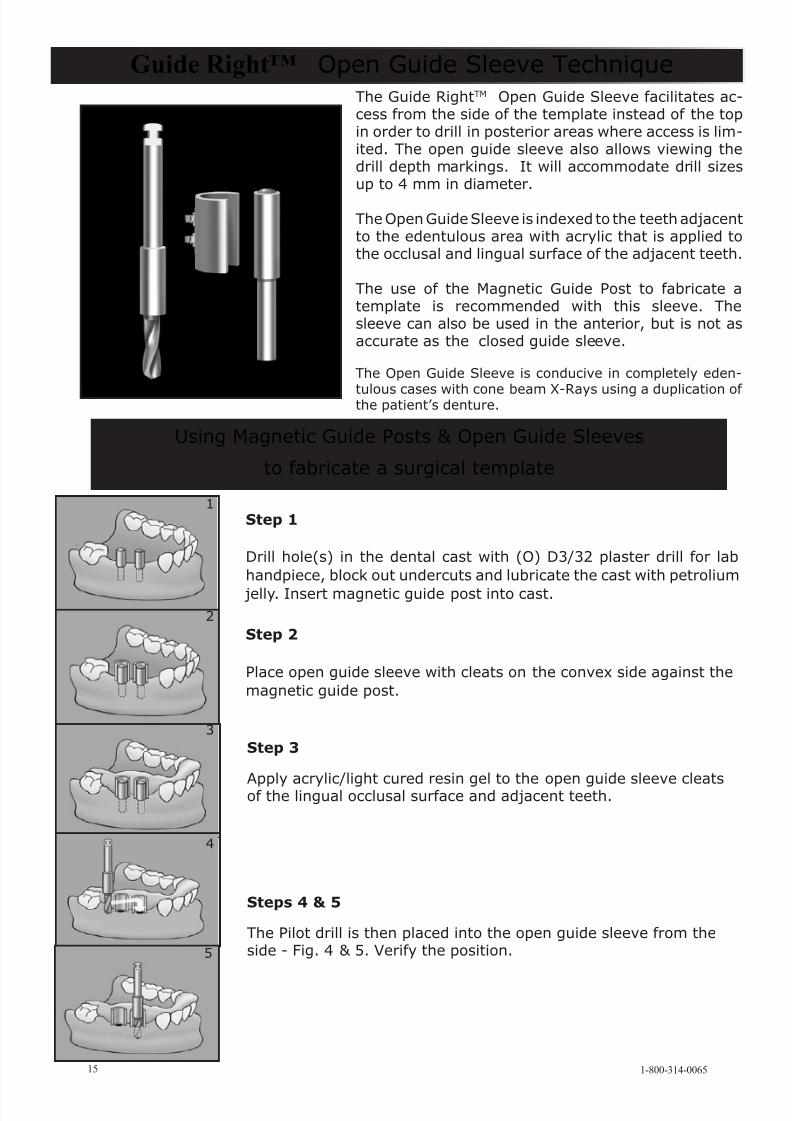
The Autoclavable Instrument Tray is a convenient autoclavablecontainer to not only sterilize your Guide RightTM Components in, butto securely organize the components individually for easy access.
Translucent lid included.
Two sizes: 2.5” X 6.0” X 0.75” 2.5” X 3.0” X 0.75”
Guide Right™ Accessories
BT
PROTRACTOR
TRAY
Generation II Guide Post Bending Tool and Stylus
Protractor
Autoclavable Instrument Tray
1-800-314-006513
Stylus
GII Guide Post
8/6/2019 Guide Right Product Catalog 2011
http://slidepdf.com/reader/full/guide-right-product-catalog-2011 15/29
The Insert Removal Tool (IRT) is required to push the insert out of the guidesleeve. This tool is a one-size-ts-all, and can be used with all insert sizes.
Guide sleeve inserts are pressed down into a sleeve to obtain apress t to prevent inserts from spinning while drilling. The surgeon (orassistant) will need to use the Insert Removal Tool (IRT) to release theinsert before placing the next larger size insert in a multi drill sequence.Inserts release easier when fabricated in an acrylic template than if grippedbetween your ngers.
The Guide Right™ Depth Gauge/Direction Indicator (2 mm diameter) is insertedinto the 2 mm osteotomy and an x-ray is taken to re-check the alignment of theosteotomy with the roots of the adjacent teeth. If the alignment is satisfactory,proceed with the increasing drill sizes. If not, minor changes in the angulationshould be made at this time with the 2 mm or a lindeman drill.
The depth of the osteotomy can also be checked with the depth gauge andmeasured at this time. The depth is determined by examining the markings on the depth gauge visible in the x-ray. The width of the top of the depthgauge (4.0 mm) is usually desired for the minimal width of an abutment.
The Guide Right™ Set-up Disks are used in place of a prosthetic wax setup or aplastic prosthetic tooth. One or more setup disk(s) is chosen to set on a cast tospace the center of the implants appropriately. The setup disks allow one to drillthrough the disk into the cast of a patient with a partially edentulous arch with a3/32” drill. The guide posts are placed in the 3/32” hole(s) in the cast after thesetup disk(s) are removed.
Sizes available: 5.5, 6.5, 7.5, 8.5, 9.5, 10.5, and 11.5 mm.Set-up disks may be purchased separately or as a complete series.
Guide Right™ Accessories
IRT
FABIN
DEPTH GAUGE
The Fabrication Insert (FABIN)is required to keep acrylic gel from entering inside the guide sleeve during the
gel and curing stage while fabricating a template. It also serves to hold the guidesleeve and guide post in place for the template. Instructions for use of the FABIN:1. Place the 3.0 mm guide post into the proposed osteotomy location
determined by the drilled hole through the center of the waxup on the cast.2. Place the the correlating size guide sleeve over the post.3. Place the appropriate size FABIN over the guide post and press-t it into the
sleeve.4. Apply acrylic gel to the seeve cleats and up over the adjacent teeth.
(see Application of Acrylic, page 20)
Available sizes include: 4.5 and 5.3 mm. (see page 11)
Insert Removal Tool
Fabrication Insert
Set-up Disks
2mm Depth Gauge / Direction Indicator
14www.deplaque.com
SUD
8/6/2019 Guide Right Product Catalog 2011
http://slidepdf.com/reader/full/guide-right-product-catalog-2011 16/29
15 1-800-314-0065
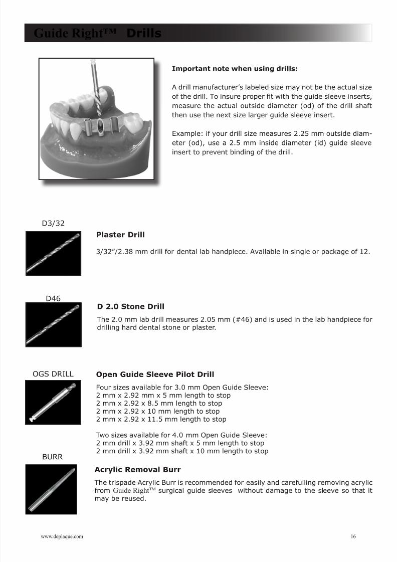
The Guide RightTM Open Guide Sleeve facilitates ac-cess from the side of the template instead of the topin order to drill in posterior areas where access is lim-ited. The open guide sleeve also allows viewing thedrill depth markings. It will accommodate drill sizesup to 4 mm in diameter.
The Open Guide Sleeve is indexed to the teeth adjacentto the edentulous area with acrylic that is applied tothe occlusal and lingual surface of the adjacent teeth.
The use of the Magnetic Guide Post to fabricate atemplate is recommended with this sleeve. Thesleeve can also be used in the anterior, but is not asaccurate as the closed guide sleeve.
The Open Guide Sleeve is conducive in completely eden-
tulous cases with cone beam X-Rays using a duplication of the patient’s denture.
Guide Right™ Open Guide Sleeve Technique
Using Magnetic Guide Posts & Open Guide Sleeves
to fabricate a surgical template
Step 1
Drill hole(s) in the dental cast with (O) D3/32 plaster drill for labhandpiece, block out undercuts and lubricate the cast with petrolium
jelly. Insert magnetic guide post into cast.
Step 3
Apply acrylic/light cured resin gel to the open guide sleeve cleatsof the lingual occlusal surface and adjacent teeth.
Steps 4 & 5
The Pilot drill is then placed into the open guide sleeve from theside - Fig. 4 & 5. Verify the position.
Step 2
Place open guide sleeve with cleats on the convex side against themagnetic guide post.
1
5
3
2
4
8/6/2019 Guide Right Product Catalog 2011
http://slidepdf.com/reader/full/guide-right-product-catalog-2011 17/29
Plaster Drill
3/32”/2.38 mm drill for dental lab handpiece. Available in single or package of 12.
D 2.0 Stone Drill
The 2.0 mm lab drill measures 2.05 mm (#46) and is used in the lab handpiece fordrilling hard dental stone or plaster.
Open Guide Sleeve Pilot Drill
Four sizes available for 3.0 mm Open Guide Sleeve:
2 mm x 2.92 mm x 5 mm length to stop2 mm x 2.92 x 8.5 mm length to stop2 mm x 2.92 x 10 mm length to stop2 mm x 2.92 x 11.5 mm length to stop
Two sizes available for 4.0 mm Open Guide Sleeve:2 mm drill x 3.92 mm shaft x 5 mm length to stop2 mm drill x 3.92 mm shaft x 10 mm length to stop
Acrylic Removal Burr
The trispade Acrylic Burr is recommended for easily and carefulling removing acrylic
from Guide RightTM
surgical guide sleeves without damage to the sleeve so that itmay be reused.
Guide Right™ Drills
D3/32
D46
OGS DRILL
BURR
Important note when using drills:
A drill manufacturer’s labeled size may not be the actual size
of the drill. To insure proper t with the guide sleeve inserts,measure the actual outside diameter (od) of the drill shaftthen use the next size larger guide sleeve insert.
Example: if your drill size measures 2.25 mm outside diam-eter (od), use a 2.5 mm inside diameter (id) guide sleeveinsert to prevent binding of the drill.
www.deplaque.com 16
8/6/2019 Guide Right Product Catalog 2011
http://slidepdf.com/reader/full/guide-right-product-catalog-2011 18/29
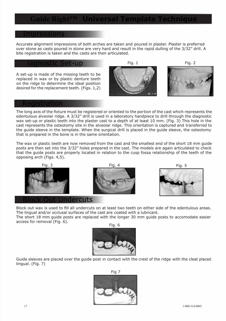
Block out wax is used to ll all undercuts on at least two teeth on either side of the edentulous areas.The lingual and/or occlusal surfaces of the cast are coated with a lubricant.The short 18 mm guide posts are replaced with the longer 30 mm guide posts to accomodate easieraccess for removal (Fig. 6).
Block Out Undercuts
Fig. 6
Guide sleeves are placed over the guide post in contact with the crest of the ridge with the cleat placedlingual. (Fig. 7)
Fig 7
Diagnostic Set-up
Accurate alignment impressions of both arches are taken and poured in plaster. Plaster is preferredover stone as casts poured in stone are very hard and result in the rapid dulling of the 3/32” drill. Abite registration is taken and the casts are then articulated.
A set-up is made of the missing teeth to bereplaced in wax or by plastic denture teethon the ridge to determine the ideal positiondesired for the replacement teeth. (Figs. 1,2)
The long axis of the xture must be registered or oriented to the portion of the cast which represents theedentulous alveolar ridge. A 3/32” drill is used in a laboratory handpiece to drill through the diagnosticwax set-up or plastic teeth into the plaster cast to a depth of at least 10 mm. (Fig. 3) This hole in thecast represents the osteotomy site in the alveolar ridge. This orientation is captured and transferred tothe guide sleeve in the template. When the surgical drill is placed in the guide sleeve, the osteotomythat is prepared in the bone is in the same orientation.
The wax or plastic teeth are now removed from the cast and the smallest end of the short 18 mm guideposts are then set into the 3/32” holes prepared in the cast. The models are again articulated to checkthat the guide posts are properly located in relation to the cusp fossa relationship of the teeth of theopposing arch (Figs. 4,5).
Guide Right™ Universal Template Technique
Impressions
Registration
Fig. 2Fig. 1
Fig. 5Fig. 3 Fig. 4
1-800-314-006517

8/6/2019 Guide Right Product Catalog 2011
http://slidepdf.com/reader/full/guide-right-product-catalog-2011 19/29
18www.deplaque.com
Fig. 11 Fig. 12 Fig. 13
Triad™ gel or other suitable acrylic is applied to the lingual and/or occlusal surfaces of the adjacentteeth and the lingual surface of the posterior guide sleeves. (Fig. 8) The guide posts are removed from
the guide sleeves prior to removing the template from the cast except with offset or angled posts.(Fig. 9) The acrylic template is then removed from the cast and any sharp edges are trimmed with anacrylic burr. Any acrylic extending over the edge of the guide sleeve should be trimmed so as not tocontact the surgical drill used in the preparation of the osteotomy site. (Fig. 10) The guide sleeves arecleaned of any acrylic with a DéPlaque Interrproximal Brush.
The template is placed in the patient’s mouth to see that it ts accurately, and for radiographicevaluation. A periapical, panorex or linear tomography or a volumetric 3-D scan can be taken todetermine the projected position of the osteotomy site. By extending the line of the edge of the guidesleeve on the radiographic image in the facial view or the cross sectional view, one can determine theprojected location of the osteotomy site (Figs. 11, 12). If the proposed trajectory is not correct, theguide sleeves are removed from the acrylic material, the necessary corrections are made, and the
template is remade. The template again should be placed in the patient’s mouth and a new radiographtaken. Fig.13 demonstrates the nal result of the accurate placement of the xture.
Guide Right™ Universal Template Technique
Fig. 8 Fig. 9 Fig. 10
Application of Acrylic
Checking Fit and Accuracy
1. Insert the Fabrication Insert (Fabin) / (X) into theGuide Sleeve (R).
2. Place the Fabrication Insert with the nested 4.5mm guide sleeve over the 3.0 mm Guide Post (G)already in the cast. The Fabrication Insert willkeep the acrylic gel out of the guide sleevewhile building your surgical template/stent.
3. When you build up the template be sure thesleeve-cleats are on the lingual/palatal side andare rmly imbedded in the acrylic
4. The Guide Sleeve Inserts should be rmlypressed down for the press t design to keepinserts from spinning while drilling the osteotomy.
Use of Serial Guide Sleeve Inserts
The surgeon (or assistant) will need to use the Insert Removal Tool (IRT) / (Y) to release the insertbefore placing the next larger size insert in a multi drill sequence.
Releasing the Insert
8/6/2019 Guide Right Product Catalog 2011
http://slidepdf.com/reader/full/guide-right-product-catalog-2011 20/29
19 1-800-314-0065
Step 1
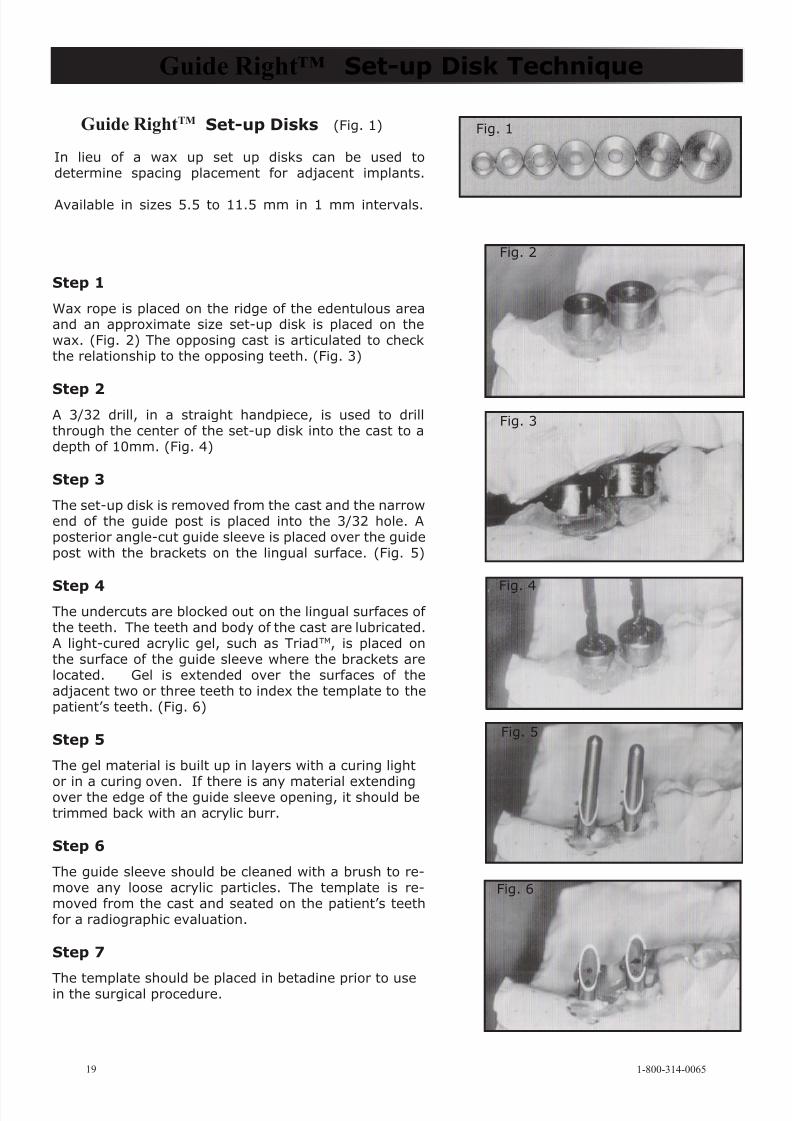
Wax rope is placed on the ridge of the edentulous areaand an approximate size set-up disk is placed on thewax. (Fig. 2) The opposing cast is articulated to checkthe relationship to the opposing teeth. (Fig. 3)
Step 2A 3/32 drill, in a straight handpiece, is used to drillthrough the center of the set-up disk into the cast to adepth of 10mm. (Fig. 4)
Step 3
The set-up disk is removed from the cast and the narrowend of the guide post is placed into the 3/32 hole. Aposterior angle-cut guide sleeve is placed over the guidepost with the brackets on the lingual surface. (Fig. 5)
Step 4The undercuts are blocked out on the lingual surfaces of the teeth. The teeth and body of the cast are lubricated.A light-cured acrylic gel, such as TriadTM, is placed onthe surface of the guide sleeve where the brackets arelocated. Gel is extended over the surfaces of theadjacent two or three teeth to index the template to thepatient’s teeth. (Fig. 6)
Step 5
The gel material is built up in layers with a curing light
or in a curing oven. If there is any material extendingover the edge of the guide sleeve opening, it should betrimmed back with an acrylic burr.
Step 6
The guide sleeve should be cleaned with a brush to re-move any loose acrylic particles. The template is re-moved from the cast and seated on the patient’s teethfor a radiographic evaluation.
Step 7
The template should be placed in betadine prior to usein the surgical procedure.
Guide Right™ Set-up Disk Technique
Fig. 2
Fig. 3
Fig. 4
Fig. 1
Fig. 5
Fig. 6
Guide RightTM Set-up Disks (Fig. 1)
In lieu of a wax up set up disks can be used todetermine spacing placement for adjacent implants.
Available in sizes 5.5 to 11.5 mm in 1 mm intervals.
8/6/2019 Guide Right Product Catalog 2011
http://slidepdf.com/reader/full/guide-right-product-catalog-2011 21/29
www.deplaque.com 20
Silverline Brushes
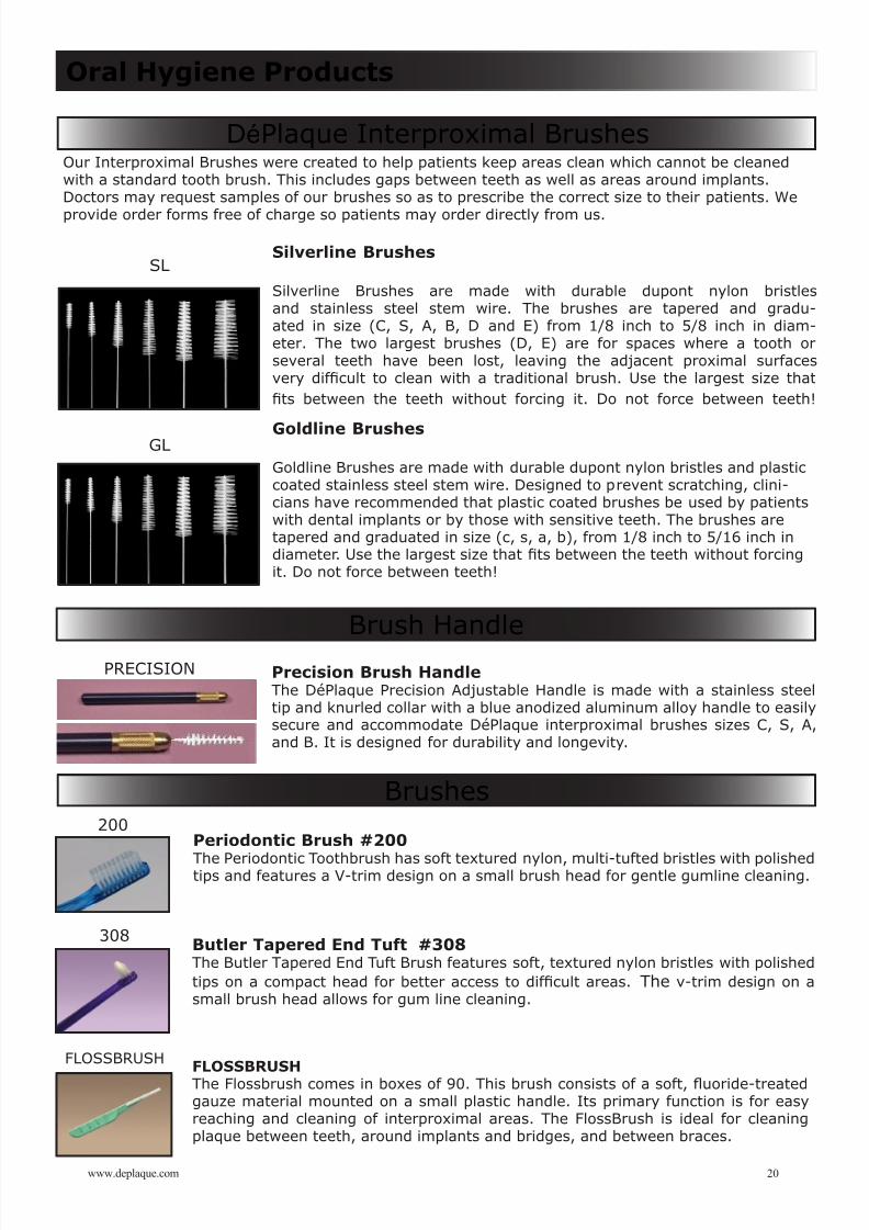
Silverline Brushes are made with durable dupont nylon bristlesand stainless steel stem wire. The brushes are tapered and gradu-ated in size (C, S, A, B, D and E) from 1/8 inch to 5/8 inch in diam-eter. The two largest brushes (D, E) are for spaces where a tooth orseveral teeth have been lost, leaving the adjacent proximal surfacesvery difcult to clean with a traditional brush. Use the largest size thatts between the teeth without forcing it. Do not force between teeth!
Goldline Brushes
Goldline Brushes are made with durable dupont nylon bristles and plasticcoated stainless steel stem wire. Designed to prevent scratching, clini-cians have recommended that plastic coated brushes be used by patientswith dental implants or by those with sensitive teeth. The brushes aretapered and graduated in size (c, s, a, b), from 1/8 inch to 5/16 inch indiameter. Use the largest size that ts between the teeth without forcingit. Do not force between teeth!
Butler Tapered End Tuft #308The Butler Tapered End Tuft Brush features soft, textured nylon bristles with polishedtips on a compact head for better access to difcult areas. The v-trim design on asmall brush head allows for gum line cleaning.
FLOSSBRUSH
The Flossbrush comes in boxes of 90. This brush consists of a soft, uoride-treatedgauze material mounted on a small plastic handle. Its primary function is for easyreaching and cleaning of interproximal areas. The FlossBrush is ideal for cleaningplaque between teeth, around implants and bridges, and between braces.
Oral Hygiene Products
SL
DéPlaque Interproximal Brushes
Brush Handle
Brushes
GL
200
308
PRECISION Precision Brush HandleThe DéPlaque Precision Adjustable Handle is made with a stainless steeltip and knurled collar with a blue anodized aluminum alloy handle to easilysecure and accommodate DéPlaque interproximal brushes sizes C, S, A,and B. It is designed for durability and longevity.
Periodontic Brush #200
The Periodontic Toothbrush has soft textured nylon, multi-tufted bristles with polishedtips and features a V-trim design on a small brush head for gentle gumline cleaning.
FLOSSBRUSH
Our Interproximal Brushes were created to help patients keep areas clean which cannot be cleanedwith a standard tooth brush. This includes gaps between teeth as well as areas around implants.Doctors may request samples of our brushes so as to prescribe the correct size to their patients. We
provide order forms free of charge so patients may order directly from us.
8/6/2019 Guide Right Product Catalog 2011
http://slidepdf.com/reader/full/guide-right-product-catalog-2011 22/29
Speak to a consultant...
Schedule an appointment with the patient for a template try-inbefore the surgery date. Take an x-ray with the template in the patient’s mouth to insure thealignment of the sleeve is where you want it. If the alignment is incorrect, break it apart by placing thetemplate into 1/4 cup of boiling water, remove from hot water with forcepts to carefully break the softenedacrylic away from the guide sleeve with your ngers. Remake it using the correct offset and/or angled
guide posts. Disinfect and retry the new template in the patient’s mouth. Take another verifying x-ray.
All guide sleeves and inserts are reusable andautoclavable. The autoclaving should be at 135 degrees C for at least 10 minutes. Regular guidesleeves are made of 303 stainless steel. The open guide sleeves are made of 410 stainless steel andcan also be autoclaved, but they will show some signs of rusting unless you use some of the surgi-cal milk* pre rinse to prevent rusting when autoclaved. Alumina ceramic guide sleeves are red at1600 degrees when they are made so they can also be autoclaved at 135 degrees C for 10 minuteswith no problems To reuse the guide sleeves, place the fabricated template in 1/4 cup of boilingwater for 1 minute to soften the acrylic. Remove it from the hot water with forcepts.Immediately and carefully break the softened acrylic away from the guide sleeve with your ngers.
The surgical template cannot be autoclaved or it willmelt. It should be placed in Betadyne for 10 minutes at room temperature, then rinsed or placed insterile water or saline for 3 seconds. Rinse once more prior to use. At the time of surgery the ap canbe reected to the palatal and the template placed on the teeth (the template will hold the palatal tis-sue out of the way.) A 3 mm hybrid drill is placed in the guide sleeve of the template. The hybrid drill isrecommended because it determines precision guidance for the drill within the 3 mm guide sleeve andfollows the 2 mm pilot hole in the same trajectory. After drilling approximately 2 mm into the bone,the template should be removed and the location of the pilot hole checked, to see that it is locatedwhere it should be in relation to the mesio-distal and bucco-lingual dimension of the alveolar crest.
If there is a concavity on the buccal or lingual aspectbelow the crest of bone, a perforation may occur. If this happens, one has to decide whether or notto change the angle of the drill which would change the angle of the xture, thus changing the longaxis of the implant body and position of the head of the implant. The original orientation can befollowed, but augmentation may be necessary. The area of perforation may be augmented with abone graft and gortex membrane. However, if the inadequacy is too severe, the ridge may have to beaugmented, the site closed, and the surgeon may have to return at a later date to place the implant.
A drill manufacturer’s labeledsize may not be the actual size of the drill. To insure proper t with any guide sleeve insert, measurethe actual outside diameter (od) of the drill shaft, then order the next size larger guide sleeve insertto prevent binding of the drill.
Consider Guide Right Kits, which contain a variety of insert sizes, to further insure accuracy of the drill position, which will ultimately result in more ac-curate implant placement.
Helpful Advice
21
To insure proper alignment ...
Components Reusable ...
Disinfecting and use ...
Complications ...
Important note when ordering Guide Sleeve Inserts ...
Alternative applications ...
S
For advice call 585.924-3190 / 800.314.0065
1-800-314-0065
* Surgical Milk is available through Henry ScheinGallon - $46.99 (8893280) 32oz. - $20.99 (9972049)

8/6/2019 Guide Right Product Catalog 2011
http://slidepdf.com/reader/full/guide-right-product-catalog-2011 23/29
8/6/2019 Guide Right Product Catalog 2011
http://slidepdf.com/reader/full/guide-right-product-catalog-2011 24/29
Guide Right™ Generation ll Bending Tool
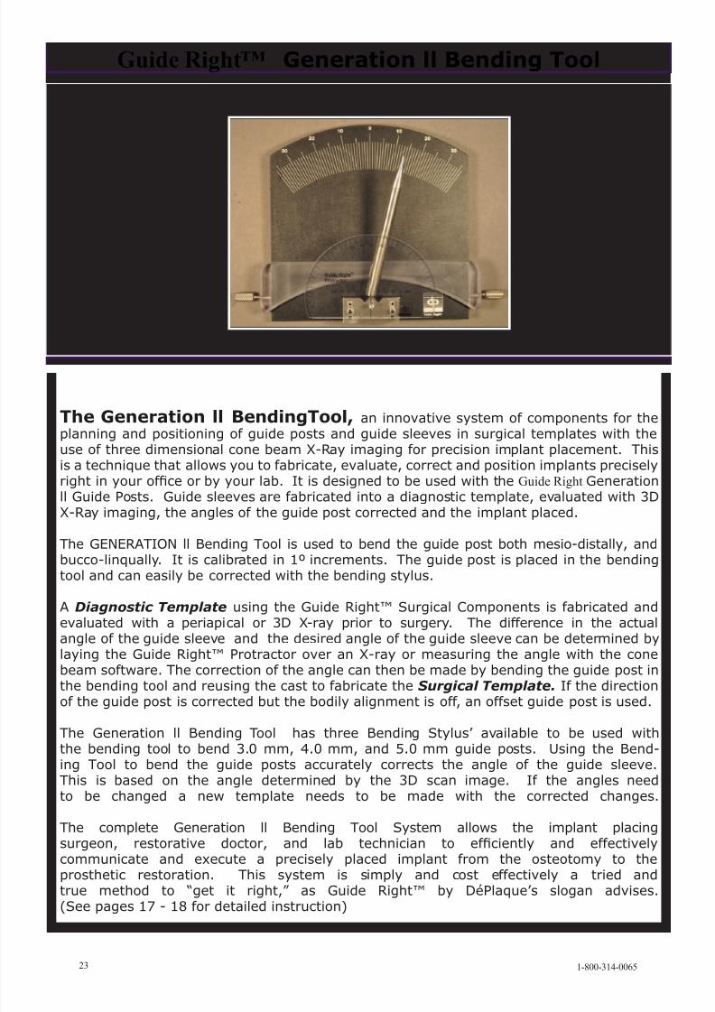
The Generation ll BendingTool, an innovative system of components for theplanning and positioning of guide posts and guide sleeves in surgical templates with theuse of three dimensional cone beam X-Ray imaging for precision implant placement. Thisis a technique that allows you to fabricate, evaluate, correct and position implants preciselyright in your ofce or by your lab. It is designed to be used with the Guide Right Generationll Guide Posts. Guide sleeves are fabricated into a diagnostic template, evaluated with 3DX-Ray imaging, the angles of the guide post corrected and the implant placed.
The GENERATION ll Bending Tool is used to bend the guide post both mesio-distally, andbucco-linqually. It is calibrated in 1º increments. The guide post is placed in the bendingtool and can easily be corrected with the bending stylus.
A Diagnostic Template using the Guide Right™ Surgical Components is fabricated andevaluated with a periapical or 3D X-ray prior to surgery. The difference in the actualangle of the guide sleeve and the desired angle of the guide sleeve can be determined bylaying the Guide Right™ Protractor over an X-ray or measuring the angle with the conebeam software. The correction of the angle can then be made by bending the guide post inthe bending tool and reusing the cast to fabricate the Surgical Template. If the directionof the guide post is corrected but the bodily alignment is off, an offset guide post is used.
The Generation ll Bending Tool has three Bending Stylus’ available to be used withthe bending tool to bend 3.0 mm, 4.0 mm, and 5.0 mm guide posts. Using the Bend-ing Tool to bend the guide posts accurately corrects the angle of the guide sleeve.This is based on the angle determined by the 3D scan image. If the angles needto be changed a new template needs to be made with the corrected changes.
The complete Generation ll Bending Tool System allows the implant placingsurgeon, restorative doctor, and lab technician to efciently and effectivelycommunicate and execute a precisely placed implant from the osteotomy to theprosthetic restoration. This system is simply and cost effectively a tried and
true method to “get it right,” as Guide Right™ by DéPlaque’s slogan advises.(See pages 17 - 18 for detailed instruction)
23 1-800-314-0065
8/6/2019 Guide Right Product Catalog 2011
http://slidepdf.com/reader/full/guide-right-product-catalog-2011 25/29
8/6/2019 Guide Right Product Catalog 2011
http://slidepdf.com/reader/full/guide-right-product-catalog-2011 26/29
Guide Right™ Generation ll Bending Tool
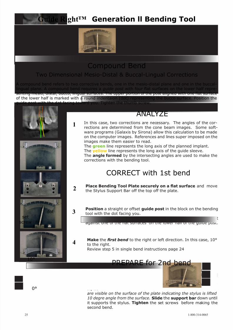
A compound bend refers to two corrective bends, one in the mesio-distal plane and one in the buccal-lingual plane. A compound bend requires a guide post with four at surfaces on the lower half repre-senting mesio, distal, bucco, lingual surfaces. The upper portion of the post aligned with one at surfaceof the lower half is marked with a round indentaion (dot) representing the bucco surface. Position theguide post with the dot facing toward you. Tighten the thumb screw.
Compound BendTwo Dimensional Mesio-Distal & Buccal-Lingual Corrections
In this case, two corrections are necessary. The angles of the cor-rections are determined from the cone beam images. Some soft-ware programs (Galaxis by Sirona) allow this calculation to be madeon the computer images. References and lines super imposed on theimages make them easier to read.The green line represents the long axis of the planned implant.The yellow line represents the long axis of the guide sleeve.The angle formed by the intersecting angles are used to make thecorrections with the bending tool.
1
2
Position a straight or offset guide post in the block on the bendingtool with the dot facing you.Using the screw driver tighten the set screw to secure the postagainst one of the at surfaces on the lower half of the guide post.
10°
Place Bending Tool Plate securely on a at surface and movethe Stylus Support Bar off the top off the plate.
Make the rst bend to the right or left direction. In this case, 10°to the right.Review step 5 in single bend instructions page 24
3
4
5
The Stylus Support Bar is required for the 2nd bend.Loosen the set screw and rotate the guide post 90° to the nextat surface, up and away from the surface of the bending plate toregister the stylus point back to zero degrees. The shadows of the
stylusare visible on the surface of the plate indicating the stylus is lifted 10 degre angle from the surface. Slide the support bar down untilit supports the stylus. Tighten the set screws before making thesecond bend.
10°
0°
setscrew
dot
25 1-800-314-0065
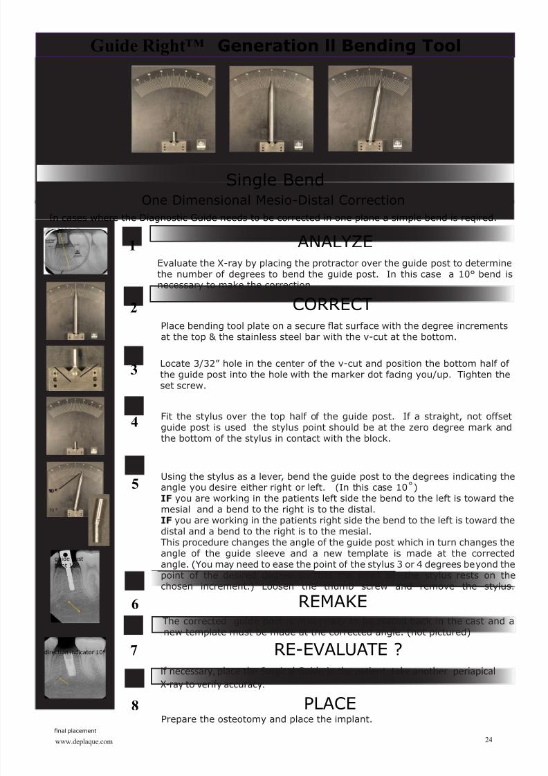
ANALYZE
CORRECT with 1st bend
PREPARE for 2nd bend
8/6/2019 Guide Right Product Catalog 2011
http://slidepdf.com/reader/full/guide-right-product-catalog-2011 27/29
8/6/2019 Guide Right Product Catalog 2011
http://slidepdf.com/reader/full/guide-right-product-catalog-2011 28/29
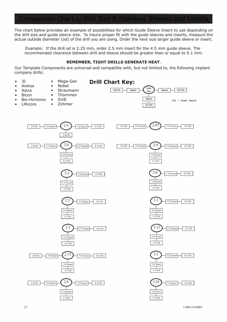
Comparison Chart for Drill Size & Stainless Sleeves and Inserts
27
The chart below provides an example of possibilities for which Guide Sleeve Insert to use depending onthe drill size and guide sleeve size. To insure proper t with the guide sleeves and inserts, measure theactual outside diameter (od) of the drill you are using. Order the next size larger guide sleeve or insert.
Example: If the drill od is 2.25 mm, order 2.5 mm insert for the 4.5 mm guide sleeve. Therecommended clearance between drill and sleeve should be greater than or equal to 0.1 mm.
REMEMBER, TIGHT DRILLS GENERATE HEAT.
Our Template Components are universal and compatible with, but not limited to, the following implantcompany drills:
• 3I• Anklos• Astra• Bicon• Bio-Horizons• Lifecore
• Mega-Gen• Nobel• Straumann• Thommen• XiVE• Zimmer
1.6 2.0 Insert 4.5 GS
2.0 GS
2.0 Insert3.0 GS
2.0 2.25 Insert 4.5 GS
2.25 Insert
5.3 GS
2.3 Insert3.0 GS
2.2 2.25 Insert 4.5 GS
2.25 Insert
5.3 GS
5.3 GS
2.3 2.5 Insert 4.5 GS
2.6 Insert
2.75 3.0 Insert 4.5 GS
3.0 Insert
5.3 GS
3.0 Insert3.0 GS
2.8 3.0 Insert 4.5 GS
3.0 Insert
5.3 GS
3.0 Insert3.0 GS
3.0 Insert 4.5 GS2.853.0 Insert3.0 GS
2.9 3.0 Insert 4.5 GS
3.0 Insert
5.3 GS
3.0 Insert3.0 GS
3.25 3.5 Insert 4.5 GS
3.6 Insert
5.3 GS
Drill Chart Key:Drill
Size Insert 4.5 GSInsert3.0 GS
Insert
5.3 GS
GS = Guide Sleeve
3.0 3.25 Insert 4.5 GS
3.6 Insert
5.3 GS
3.1 3.25 Insert 4.5 GS
3.6 Insert
5.3 GS
3.15 3.25 Insert 4.5 GS
3.6 Insert
5.3 GS
2.5 2.75 Insert 4.5 GS
2.6 Insert
5.3 GS
3.2 3.25 Insert 4.5 GS
3.6 Insert
5.3 GS
1-800-314-0065

8/6/2019 Guide Right Product Catalog 2011
http://slidepdf.com/reader/full/guide-right-product-catalog-2011 29/29