Embed Size (px)
Citation preview
CNR – Advisory Committee on Technical Recommendations for Construction
CNR-DT 203/2006
ROME – CNR June 2007
NATIONAL RESEARCH COUNCIL
ADVISORY COMMITTEE
ON TECHNICAL RECOMMENDATIONS FOR CONSTRUCTION
Guide for the Design and Construction
of Concrete Structures Reinforced
with Fiber-Reinforced Polymer Bars

This document is subject to copyright.
No part of this publication may be stored in a retrieval system, or
transmitted in any form or by any means
– electronic, mechanical, recording, or otherwise –
without the prior written permission
of the Italian National Research Council.
The reproduction of this document is permitted
for personal, noncommercial use.
CNR-DT 203/2006
i
CONTENTS
1 FOREWORD................................................................................................................................. 1
1.1 PUBLIC HEARING ................................................................................................................. 3
2 INTRODUCTION......................................................................................................................... 4
2.1 SYMBOLS ............................................................................................................................... 4
3 MATERIALS................................................................................................................................. 6
3.1 MANUFACTURING TECHNIQUES ..................................................................................... 6
3.2 CHARACTERISTICS OF FRP BARS .................................................................................... 6
3.2.1 Geometrical properties .......................................................................................................6
3.2.2 Strength and Young’s modulus of elasticity for tensile stress in the longitudinal
direction (bar axis)..............................................................................................................6
3.2.3 Coefficients of thermal expansion......................................................................................7
3.2.4 Static fatigue.......................................................................................................................8
3.2.5 Bar-concrete bond ..............................................................................................................8
3.3 FRP GRIDS CHARACTERISTICS......................................................................................... 8
3.4 TECHNICAL DATA SHEET FOR FRP BARS...................................................................... 8
3.5 CERTIFICATION AND FACTORY PRODUCTION CONTROL ........................................ 8
3.6 ACCEPTANCE ........................................................................................................................ 9
4 BASIS OF DESIGN .................................................................................................................... 10
4.1 BASIC REQUIREMENTS..................................................................................................... 10
4.2 STRUCTURE SERVICE LIFE.............................................................................................. 10
4.3 DURABILITY REQUIREMENTS ........................................................................................ 10
4.4 REINFORCEMENT: GENERAL PRINCIPLES................................................................... 11
4.4.1 Introduction ......................................................................................................................11
4.4.2 Design loads .....................................................................................................................11
4.4.3 Material properties............................................................................................................11
4.4.4 Design capacity ................................................................................................................12
4.5 PARTIAL FACTORS ............................................................................................................ 12
4.5.1 Material partial factors m.................................................................................................12
4.6 SPECIAL DESIGN PROBLEMS AND RELEVANT CONVERSION FACTORS............. 12
4.6.1 Environmental conversion factor a .................................................................................12
4.6.2 Loading modes and conversion factors for long-term effects l .....................................13
4.7 FLEXURE .............................................................................................................................. 14
4.7.1 Introduction ......................................................................................................................14
4.7.2 Analysis of the behaviour for ultimate limit state ............................................................14 4.7.2.1 Design basis ........................................................................................................................ 14
4.7.2.2 Member flexural capacity.................................................................................................... 14
4.7.2.3 Minimum reinforcement ..................................................................................................... 16
4.7.3 Service limit state analysis ...............................................................................................16 4.7.3.1 Design assumptions............................................................................................................. 16
4.7.3.2 Stress limitation................................................................................................................... 17
4.7.3.3 Deflection control................................................................................................................ 17
4.7.3.4 Crack control ....................................................................................................................... 18
4.8 SHEAR ................................................................................................................................... 20
4.8.1 Introduction ......................................................................................................................20
4.8.2 Basis for design ................................................................................................................20 4.8.2.1 Members without shear reinforcement................................................................................ 20
4.8.2.2 Elements with shear reinforcement ..................................................................................... 20
CNR-DT 203/2006
ii
4.8.3 Minimum shear reinforcement .........................................................................................21
4.9 SECONDARY FRP REINFORCEMENT ............................................................................. 21
4.10 DEVELOPMENT LENGTH.................................................................................................. 21
4.11 CONSTRUCTION DETAILS................................................................................................ 22
5 APPENDIX A (MANUFACTURING TECHNIQUES OF FRP BARS AND GRIDS) ........ 24
5.1 FRP BARS.............................................................................................................................. 24
5.2 FRP GRIDS ............................................................................................................................ 26
6 APPENDIX B (TEST METHODS FOR CHARACTERISING FRP BARS) ....................... 27
6.1 METHOD FOR CALCULATING THE GEOMETRIC PROPERTIES ............................... 27
6.2 METHOD FOR CALCULATING THE MECHANICAL PROPERTIES ............................ 27
7 APPENDIX C .............................................................................................................................. 30
7.1 TECHNICAL DATA SHEET FOR FRP BARS.................................................................... 30
8 APPENDIX D .............................................................................................................................. 32
8.1 SELECTION AND TESTING OF FRP BARS: TASKS AND RESPONSIBILITIES
OF PROFESSIONALS........................................................................................................... 32
9 APPENDIX E (CALCULATING DEFLECTIONS AND CRACK WIDTHS FOR
FLEXURAL ELEMENTS OF CONCRETE REINFORCED WITH FRP BARS) ............. 34
10 ACKNOWLEDGEMENTS........................................................................................................ 35
CNR-DT 203/2006
1
1 FOREWORD The present document adds to the series of documents recently issued by the CNR on the structural
use of fiber-reinforced polymer (FRP) composites, started with the publication of CNR-DT
200/2004. The documents published refer to the use of externally bonded systems for strengthening
concrete and masonry structures (CNR-DT 200/2004), timber structures (CNR-DT 201/2005) and
structural steel (CNR-DT 202/2005). The subject of the present document is the use of FRP bars as
internal reinforcement in concrete structures.
The use of fiber-reinforced polymer composites, in substitution for steel, for concrete structural
elements is a widespread practice in many countries. The peculiar characteristic of FRP materials of
not being susceptible to corrosion phenomena makes their use particularly suitable in different
situations.
Several international guidelines are currently available supporting the design, construction and
control of such structures.
From a theoretical perspective, there are no conceptual differences in relation to the classical theory
of steel reinforced concrete elements. What does need to be taken into account, is the different
mechanical behavior of FRP material, whose constitutive law is fundamentally linear elastic up to
failure.
There are five guidelines currently available in English, listed from the most recently issued to the
most dated: the document issued by the fib (Task Group 9.3, 2005); the American Concrete Institute
(ACI 440.1R-03, 2003); the two documents published in Canada (CAN/CSA-S6-02, 2002 for
buildings, and CAN/CSA-S6-00, 2000 for bridges) and the Japanese document (JSCE, 1997).
A complete reference to these documents can be found in the following:
fib, 2005, “FRP Reinforcement for reinforced concrete Structures”, Task Group 9.3 (Fiber Reinforced Polymer) Reinforcement for Concrete Structures, Lausanne, Switzerland.
ACI 440.1R-03, 2003, “Guide for the Design and Construction of Concrete Reinforced
with FRP Bars”, American Concrete Institute, Farmington Hills, MI, USA.
CAN/CSA-S6-02, 2002, “Design and Construction of Building Components with Fiber-
Reinforced Polymers,” CAN/CSA S806-02, Canadian Standards Association, Rexdale,
Canada.
CAN/CSA-S6-00, 2000, “Canadian High Bridge Design Code,” Clause 16.8.6, Canadian
Standard Association (CSA) International, Toronto, Ontario, Canada.
Japan Society of Civil Engineers (JSCE), 1997, “Recommendation for Design and
construction of Concrete Structures Using Continuous Fiber Reinforcing Materials”,
Concrete Engineering Series No. 23, Tokyo, Japan.
All the aforementioned documents are written using the semi-probabilistic approach for both
ultimate (ULS) and serviceability (SLS) limit states.
There are several reasons that make the use of FRP bars preferable to conventional steel ones.
As above mentioned, these innovative bars are not susceptible to corrosion which makes them
suitable for marine structures as well as structures exposed to harsh environments. Furthermore,
glass FRP composites (GFRP) are nonconductive and therefore can be used effectively when stray
currents are an issue, as in the case of structures serving rail transportation (railway or subway
lines), either outdoor or in tunnels. Even bridge decks used as railway overpasses can be affected by
the same phenomenon.
In the building industry, the use of this new technology can be adopted for the construction of
building slabs for civil or industrial use.
The reasons that lead to choosing FRP in this case can be related not only to durability issues, but
also to the possibility of taking advantage of specific properties of composite materials, such as
CNR-DT 203/2006
2
magnetic transparency. The latter is of fundamental importance in the construction of hospital
rooms to avoid interference where Magnetic Resonance Imager (MRI) units are located.
There are further attractive and promising uses of composites materials in the building of temporary
structures and tunnel coverings.
It is important that the designer be informed about both the benefits and the drawbacks of composite
materials to take full advantage of the former and properly reduce the latter. This target is
particularly important in order to ensure a satisfactory service life of the designed structures. In this
document the most considerable aspects related to this issue will be highlighted, both in terms of
design as well as construction requirements.
For a wider and more exhaustive presentation of the constitutive and rheological properties of FRP,
the reader should refer to the technical document CNR-DT 200/2004 as well as specialised
textbooks available.
The purpose of this guide is to provide an advisory document for the design, construction and
control of concrete structures reinforced with FRP bars. The approach followed is that of the limit
states semi-probabilistic method, while the format adopted is that of ‘principles’ and ‘practical
rules’ in compliance with the classical style of Eurocodes.
A guideline, by its nature, is not a binding regulation, but merely represents an aid for practitioners
interested in the field of composites. Nevertheless, the responsibility of the operated choices
remains with the designer.
Within the seismic field, the methods assuming plastic redistribution capability are not applicable,
since the mechanical behavior of concrete elements reinforced with FRP bars is essentially elastic.
Consequently, the nearly complete lack of ductility displayed by FRP reinforced concrete structures
shall be taken into account.
In the case of primary structural elements subjected to seismic actions, the design spectrum shall be
derived from the elastic spectrum by setting the structural factor to an appropriate value to account
for the elastic behavior shown by an element reinforced with FRP bars.
This Technical Document has been prepared by a Task Group whose members are:
ASCIONE Prof. Luigi - University of Salerno
BENEDETTI Prof. Andrea - University of Bologna
BERARDI Dr. Valentino Paolo - University of Salerno
CERSOSIMO Dr. Giuseppe - Interbau S.r.l.- Milano
COSENZA Prof. Edoardo - University “Federico II”- Napoli
FEO Prof. Luciano - University of Salerno
FICO Dr. Raffaello - University “Federico II”- Napoli
FRASSINE Prof. Roberto - Polytechnic of Milano
GIAMUNDO Dr. Aniello - ATP Pultrusion - Angri (SA)
GREMEL Dr. Doug - Hughes Brothers - Nebraska, U.S.A.
GRIMALDI Prof. Antonio - University “Tor Vergata” - Roma
MACERI Prof. Franco - University “Tor Vergata” - Roma
MANFREDI Prof. Gaetano - University “Federico II” - Napoli
MONTI Prof. Giorgio - University “La Sapienza” - Roma
NANNI Prof. Antonio - University “Federico II”- Napoli
PARRETTI Dr. Renato - University “Federico II”- Napoli
PECCE Prof. Maria Rosaria - University of Sannio - Benevento
PISANI Prof. Marco Andrea - Polytechnic of Milano
POGGI Prof. Carlo - Polytechnic of Milano
PROTA Dr. Andrea - University “Federico II”- Napoli
SAVOIA Prof. Marco - University of Bologna
VAGO Mr. Giuseppe - Sireg - Arcore (MI)
CNR-DT 203/2006
3
Coordinator:
GRIMALDI Prof. Antonio.
General Coordinator:
ASCIONE Prof. Luigi.
Technical Secretariat:
FEO Prof. Luciano, ROSATI Prof. Luciano.
1.1 PUBLIC HEARING
After its publication, this document CNR-DT 203/2006 was subject to a public hearing. Following
the public hearing, some modifications and/or integrations have been made to the document
including corrections of typos, additions of subjects that had not been dealt with in the original
version, and elimination of others deemed not to be relevant.
This Technical Document has been approved as a final version on 18/06/2007, including the
modifications derived from the public hearing, by the “Advisory Committee on Technical
Recommendation for Construction”, whose members are:
ANGOTTI Prof. Franco - University of Firenze
ASCIONE Prof. Luigi - University of Salerno
BARATTA Prof. Alessandro - University “Federico II”- Napoli
COSENZA Prof. Edoardo - University “Federico II”- Napoli
GIANGRECO Prof. Elio - University “Federico II”- Napoli
JAPPELLI Prof. Ruggiero - University “Tor Vergata” - Roma
MACERI Prof. Franco, Chairman - University “Tor Vergata” - Roma
MAZZOLANI Prof. Federico Massimo - University “Federico II”- Napoli
PINTO Prof. Paolo Emilio - University “La Sapienza” - Roma
POZZATI Prof. Piero - University of Bologna
SOLARI Prof. Giovanni - University of Genova
URBANO Prof. Carlo - Polytechnic of Milano
VINCI Dr. Roberto - Italian National Research Council
ZANON Prof. Paolo - University of Trento
CNR-DT 203/2006
4
2 INTRODUCTION
(1) The subject of this document regards structures reinforced with non-prestressed FRP bars.
Nevertheless, the possibility that elements of such structures have traditional steel reinforcement is
also accounted for.
(2) Principles and practical rules included in this document can not be used for prestressed
structures using FRP tendons.
Such applications, however, have already been developed in several countries and need specific
guidance, depending mainly on both pre-stressing technology and selected anchoring device, as
well as on materials properties, particularly with reference to long term effects under high stress
conditions.
2.1 SYMBOLS
General notations
(.)c value of quantity (.) for concrete
(.)d design value of quantity (.)
(.)f value of quantity (.) for FRP composite
(.)k characteristic value of quantity (.)
(.)R value of quantity (.) as resistance
(.)S value of quantity (.) as demand
Uppercase Roman letters
Ab equivalent area of FRP bar
Ac area of concrete cross section, net of steel reinforcement
Af area of FRP reinforcement
Afw area of FRP shear reinforcement within spacing s
Ap equivalent area of FRP specimen
Ec Young’s modulus of elasticity of concrete
Ef Young’s modulus of elasticity of FRP reinforcement
Es Young’s modulus of elasticity of steel reinforcement
MRd flexural capacity of FRP reinforced element
MSd factored moment
Rck characteristic cubic compressive strength of concrete
Tg glass transition temperature of resin
VRd shear capacity of FRP reinforced element
VRd,ct concrete contribution to the shear capacity
VRd,f FRP contribution to the shear capacity
VRd,max maximum concrete contribution to the shear capacity
VSd factored shear force
Lowercase Roman letters
b width of the section
d distance from extreme compression fiber to centroid of tension reinforcement
db equivalent diameter of FRP bar
fc (cylindrical) concrete compressive strength
fcd design compressive strength of concrete
CNR-DT 203/2006
5
fck characteristic compressive strength of concrete
fctd design tensile strength of concrete
ffd design tensile strength of FRP reinforcement
ffk characteristic tensile strength of FRP reinforcement
h section depth
s FRP stirrups spacing
x distance from extreme compression fiber to neutral axis
Lowercase Greek letters
m partial factor for materials
Rd partial factor for resistance models
c concrete strain of compression fiber
cu ultimate strain of concrete in compression
f strain of FRP reinforcement
fd design strain of FRP reinforcement
fk characteristic rupture strain of FRP reinforcement
l flexural FRP reinforcement ratio
c stress in the concrete
f stress in the FRP reinforcement
Rd design shear stress
CNR-DT 203/2006
6
3 MATERIALS
(1) FRP composite materials considered in this document are limited to bars and grids
manufactured using thermosetting resins and glass, carbon or aramid fibers.
(2)P The mechanical properties of such materials depend mainly on both matrix and fibers type,
as well as on their volume fraction.
(3) Based on the experience and knowledge acquired, this guide is restricted to the use of bars
and grids made of fiber reinforced material using thermosetting resin with a fiber volume fraction
greater than 50%.
(4)P Bond properties of FRP bars to concrete are influenced mainly by the manufacturing process
as well as the characteristics of the bar surface.
(5) In addition to the parameters characterizing the bars, the bond properties of the grids also
depend on the way the grid elements are interconnected.
3.1 MANUFACTURING TECHNIQUES
(1) The main manufacturing techniques of FRP bars and grids as well as the most popular
typologies available on the market are reported in Appendix A.
3.2 CHARACTERISTICS OF FRP BARS
(1)P The determination of both the geometrical and mechanical properties of FRP bars requires
the use of specific procedures.
3.2.1 Geometrical properties
(1)P In relation to the considerable variety of bars available on the market, also in terms of cross
section geometry, it is suitable referring to an equivalent (or nominal) circular cross section, with
both the diameter and area being defined properly.
(2) One of the procedures for the evaluation of equivalent diameter and area is described in
Appendix B.
3.2.2 Strength and Young’s modulus of elasticity for tensile stress in the longitudinal direction (bar axis)
(1)P Similar to pre-formed composites, FRP bars are characterized by a unidirectional array of
fibers, generally having a volume fraction ranging between 50% and 70%.
Only for small diameter bars, this circumstance allows using the rule of mixtures to determine the
proper values of the mechanical properties such as stiffness and strength.
However, the derived values represent only an estimation of the real values, which are often
approximated to excess. In fact, these values do not take into account the influence of further
significant parameters, such as the bond between the fibers and matrix, the presence of
manufacturing defects and voids, as well as fiber misalignment.
(2)P In order to evaluate the mechanical properties of the FRP bars, consideration shall be given
to suitable experimental tests to obtain significant statistic values. Values provided by
manufacturers shall be derived according to the principles described in Section 3.5.
CNR-DT 203/2006
7
(3) There are two approaches to evaluate the strength and Young’s modulus of elasticity for
tensile stress in the longitudinal direction. The first is based on pure tensile tests, while the second
on flexural tests carried out on bar specimens embedded in concrete beams. Although the latter
generally gives higher strength values, the direct test is usually preferred from a practical
standpoint. Further information is reported in Appendix B.
(4) Strength and stiffness values provided by the manufacturer shall refer to the bar equivalent
area.
(5) All types of FRP bars can be used provided that the characteristic strength is not lower than
400 MPa, and the average value of the Young’s modulus of elasticity in the longitudinal direction is
not lower than 100 GPa for carbon FRP bars, 35 GPa for glass FRP bars, and 65 GPa for aramid
bars.
3.2.3 Coefficients of thermal expansion
(1)P The coefficients of thermal expansion of FRP bars in both longitudinal, l, and transversal,
t, directions, are strictly related to those of the single phases (matrix and fibers) of the composite
material.
In particular, as the volume fraction of the fibers increases, the value of l approaches that of the
fibers; for lower volume fraction, l can be approximated to the coefficient of thermal expansion of
the matrix.
For more in-depth indications on thermal properties of the single phase refer to the technical
document CNR-DT 200/2004.
(2) Typical values of the coefficient of thermal expansion in the longitudinal and transversal
directions, l and t, respectively, of composite bars with a fibers volume fraction ranging between
50% and 70%, are reported in Table 3-1.
Table 3-1 – Coefficients of thermal expansion
Bar l
[10-6
°C-1
]t
[10-6
°C-1
]
AFRP -6.0 -2.0 60.0 80.0
CFRP -2.0 0.0 23.0 32.0
GFRP 6.0 10.0 21.0 23.0
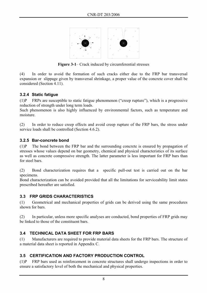
(3)P Higher values of the transversal coefficients of thermal expansion, combined with the
Poisson’s effect in the case of compressed reinforcements, can be responsible for circumferential
tensile stresses that allow the formation of cracks in the radial direction (Figure 3-1).
These cracks may endanger the concrete-FRP bond with undesirable consequences on the structural
behavior both under service and ultimate conditions.
CNR-DT 203/2006
8
Figure 3-1– Crack induced by circumferential stresses
(4) In order to avoid the formation of such cracks either due to the FRP bar transversal
expansion or slippage given by transversal shrinkage, a proper value of the concrete cover shall be
considered (Section 4.11).
3.2.4 Static fatigue
(1)P FRPs are susceptible to static fatigue phenomenon (“creep rupture”), which is a progressive
reduction of strength under long term loads.
Such phenomenon is also highly influenced by environmental factors, such as temperature and
moisture.
(2) In order to reduce creep effects and avoid creep rupture of the FRP bars, the stress under
service loads shall be controlled (Section 4.6.2).
3.2.5 Bar-concrete bond
(1)P The bond between the FRP bar and the surrounding concrete is ensured by propagation of
stresses whose values depend on bar geometry, chemical and physical characteristics of its surface
as well as concrete compressive strength. The latter parameter is less important for FRP bars than
for steel bars.
(2) Bond characterization requires that a specific pull-out test is carried out on the bar
specimens.
Bond characterization can be avoided provided that all the limitations for serviceability limit states
prescribed hereafter are satisfied.
3.3 FRP GRIDS CHARACTERISTICS
(1) Geometrical and mechanical properties of grids can be derived using the same procedures
shown for bars.
(2) In particular, unless more specific analyses are conducted, bond properties of FRP grids may
be linked to those of the constituent bars.
3.4 TECHNICAL DATA SHEET FOR FRP BARS
(1) Manufacturers are required to provide material data sheets for the FRP bars. The structure of
a material data sheet is reported in Appendix C.
3.5 CERTIFICATION AND FACTORY PRODUCTION CONTROL
(1)P FRP bars used as reinforcement in concrete structures shall undergo inspections in order to
ensure a satisfactory level of both the mechanical and physical properties.
CNR-DT 203/2006
9
The following is required:
The Factory Production Control (FPC) shall relate to the geometrical, mechanical (stiffness
and strength) and physical properties of the FRP bars as discussed in the following Sections.
The bar manufacturer shall use basic materials (fiber and resin) certified by their supplier.
(2)P The sampling as well as the tests on the product samples shall be regularly carried out on the
manufacturing plant. Both the mechanical and physical qualification tests shall be carried out by a
certified laboratory provided with the necessary equipment and experience in the characterization of
composite materials. If the factory laboratory is either not available or not certified, the qualification
tests shall be carried out by an external laboratory certified in the characterization of composite
materials.
The mechanical characteristics, reported in the technical data sheets of the products, shall be
obtained through a statistical analysis, including the characteristic values, percentile, sample mean,
sample standard deviations, confidence intervals, and the number of samples tested. Suitable partial
factors of the semi-probabilistic method should be employed on the characteristic evaluated values.
(3) Test methods for characterising the FRP bar mechanical properties bars are reported in
Appendix C. For further requirements, international specific standards (e.g., ACI, ISO and ASTM
standards) are available.
3.6 ACCEPTANCE
(1) The following operators shall take part in the acceptance process of the FRP bars:
Manufacturer;
Designer;
Contractor;
Construction manager;
Test laboratories;
Inspector.
The tasks and responsibilities of these professionals are reported in Appendix D.
CNR-DT 203/2006
10
4 BASIS OF DESIGN (1)P The design of concrete structures reinforced with FRP bars shall satisfy strength and
serviceability requirements.
(2)P The design of concrete structures shall not rely upon strength and stiffness contributions
provided by the compressed FRP bars.
(3)P Special care is required in the case of structural analysis, where the almost complete lack of
ductility of the FRP reinforced concrete structures shall be taken into account
More specifically, the analyses assuming either the elastic or elastic-plastic redistribution capability
are not applicable.
(4)P Specific fire resistance analyses of the structural element shall be performed according to
current fire regulations, taking into account the value of the glass transition temperature, Tg.
Some structural typologies, such as bridge decks and more generally those less susceptible to fire
problems, do not require a specific fire verifications.
(5) The use of bent bars is allowed in compliance with Section 4.11.
4.1 BASIC REQUIREMENTS
(1)P Basic requirements related to the design of FRP reinforced concrete structures can be
considered fulfilled when:
Suitable materials are chosen;
A careful choice of construction details is ensured;
Controlling procedures for design, manufacturing, construction and use are defined.
4.2 STRUCTURE SERVICE LIFE
(1)P For the purposes of FRP design of reinforced concrete structural elements, the conventional
service life and the corresponding levels of the design loads according to the current building code
shall be considered.
(2)P If FRP bars are used for the construction of temporary reinforced concrete structures, the
design loads and the safety assessment shall be adjusted to the structure service life (less than one
year), according to specific current regulations.
4.3 DURABILITY REQUIREMENTS
(1)P The structure shall be designed by taking into account both the environmental conditions as
well as the maintenance program.
(2) In order to ensure proper durability, the following should be considered:
The intended or foreseeable use;
The expected environmental conditions;
The composition, properties and performance of the materials employed.
CNR-DT 203/2006
11
(3)P Special design problems (environmental actions, loading modes, etc.) shall be identified at
the first stage of design in order to evaluate their relevance to the durability of the FRP
reinforcement.
4.4 REINFORCEMENT: GENERAL PRINCIPLES
4.4.1 Introduction
(1)P Design of FRP reinforced concrete members shall be performed at both the ultimate and
service limit states, as defined by the current building code.
(2) Verification of one limit state may be omitted provided that sufficient information are avail-
able to prove that it is satisfied by another one.
(3)P The following inequality shall always be met:
d dE R , (4.1)
where dE and dR are the factored design values of the demand and the corresponding factored
capacity, respectively, within the limit state being considered.
(4) The design values are obtained from the characteristic values through suitable partial factors,
to be chosen according to the current building code, or indicated in this document with reference to
specific issues dealt herewith.
4.4.2 Design loads
(1) Design loads shall be chosen according to the current building code.
4.4.3 Material properties
(1)P The properties of the FRP bars shall be determined through standardized laboratory tests,
such as those indicated in the present document.
(2) Strength and strain properties of the FRP bars are quantified by the corresponding
characteristic values. Only the stiffness parameters (Young’s modulus of elasticity) are evaluated
through the corresponding average values.
(3) The design value, dX , of the generic strength and/or strain property of a material, in
particular of a FRP bar, can be expressed as follows:
k
d
m
XX , (4.2)
where kX is the characteristic value of the property being considered, is a conversion factor
accounting for special design problems, and m is the material partial factor.
(4) The conversion factor is obtained by multiplying the environmental conversion factor, a ,
by the conversion factor due to long-term effects, l . Possible values to be assigned to such factors
are reported in Table 4-1 and Table 4-2, respectively. Values obtained from experimental tests can
be assigned when available. Such values are obtained by testing FRP bars to a constant stress equal
CNR-DT 203/2006
12
to the maximum stress at service for environmental conditions similar to that encountered by the
structure in its life and by evaluating the bar residual strength over time in compliance with the
standard ISO TC 71/SC 6 N.
4.4.4 Design capacity
(1) The design strength, dR can be expressed as follows:
d d,i d,i
Rd
1;R R X a , (4.3)
where R is a function depending upon the specific mechanical model considered (e.g. flexure,
shear) and Rd is a partial factor covering uncertainties in the capacity model; unless otherwise
specified, such factor shall be set equal to 1. The arguments of the function R are typically the
mechanical and geometrical parameters, whose design and nominal values are d,iX and id,a ,
respectively.
4.5 PARTIAL FACTORS
4.5.1 Material partial factors m
(1) For ultimate limit states, the partial factor m for FRP bars, denoted by f , shall be set equal
to 1.5.
(2) For serviceability limit states, the value to be assigned to the partial factor is f 1.
(3) The partial factor prescribed by the current building code shall be assigned for concrete.
4.6 SPECIAL DESIGN PROBLEMS AND RELEVANT CONVERSION FACTORS
(1) Reference values to be assigned to the conversion factor that affect durability and
behaviour of FRP reinforced concrete members are reported in the next sections.
4.6.1 Environmental conversion factor a
(1)P The mechanical properties (e.g. tensile strength, ultimate strain, and Young’s modulus of
elasticity) of FRP bars degrade under specific environmental conditions such as alkaline
environment and moisture (water and salt added to water).
(2) Effects of the alkaline environment. The water contained in concrete pores may be
responsible for the degradation of the polymeric matrix. The damage to the polymeric matrix due to
the alkali attack is typically more dangerous than that due to moisture.
(3) Effects of moisture (water and salt added to water). The main effects of moisture absorption
concern the matrix and are: plasticization, reduction of glass transition temperature, strength
reduction, and stiffness reduction (less pronounced). The absorption of moisture depends on the
types of polymeric matrix, the matrix-fiber interface, as well as the composition and quality of the
bars.
CNR-DT 203/2006
13
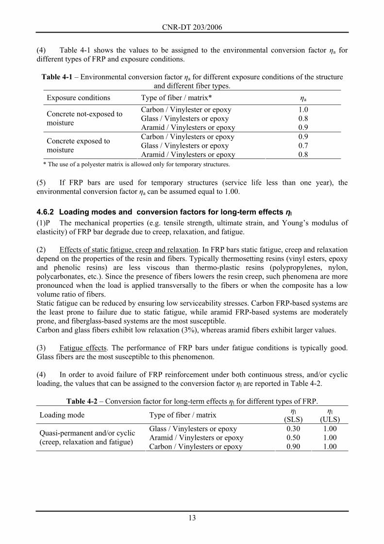
(4) Table 4-1 shows the values to be assigned to the environmental conversion factor a for
different types of FRP and exposure conditions.
Table 4-1 – Environmental conversion factor a for different exposure conditions of the structure
and different fiber types.
Exposure conditions Type of fiber / matrix* a
Carbon / Vinylester or epoxy 1.0
Glass / Vinylesters or epoxy 0.8 Concrete not-exposed to
moisture Aramid / Vinylesters or epoxy 0.9
Carbon / Vinylesters or epoxy 0.9
Glass / Vinylesters or epoxy 0.7 Concrete exposed to
moisture Aramid / Vinylesters or epoxy 0.8
* The use of a polyester matrix is allowed only for temporary structures.
(5) If FRP bars are used for temporary structures (service life less than one year), the
environmental conversion factor a can be assumed equal to 1.00.
4.6.2 Loading modes and conversion factors for long-term effects l
(1)P The mechanical properties (e.g. tensile strength, ultimate strain, and Young’s modulus of
elasticity) of FRP bar degrade due to creep, relaxation, and fatigue.
(2) Effects of static fatigue, creep and relaxation. In FRP bars static fatigue, creep and relaxation
depend on the properties of the resin and fibers. Typically thermosetting resins (vinyl esters, epoxy
and phenolic resins) are less viscous than thermo-plastic resins (polypropylenes, nylon,
polycarbonates, etc.). Since the presence of fibers lowers the resin creep, such phenomena are more
pronounced when the load is applied transversally to the fibers or when the composite has a low
volume ratio of fibers.
Static fatigue can be reduced by ensuring low serviceability stresses. Carbon FRP-based systems are
the least prone to failure due to static fatigue, while aramid FRP-based systems are moderately
prone, and fiberglass-based systems are the most susceptible.
Carbon and glass fibers exhibit low relaxation (3%), whereas aramid fibers exhibit larger values.
(3) Fatigue effects. The performance of FRP bars under fatigue conditions is typically good.
Glass fibers are the most susceptible to this phenomenon.
(4) In order to avoid failure of FRP reinforcement under both continuous stress, and/or cyclic
loading, the values that can be assigned to the conversion factor l are reported in Table 4-2.
Table 4-2 – Conversion factor for long-term effects l for different types of FRP.
Loading mode Type of fiber / matrix l
(SLS)l
(ULS)
Glass / Vinylesters or epoxy 0.30 1.00
Aramid / Vinylesters or epoxy 0.50 1.00 Quasi-permanent and/or cyclic
(creep, relaxation and fatigue) Carbon / Vinylesters or epoxy 0.90 1.00
CNR-DT 203/2006
14
4.7 FLEXURE
4.7.1 Introduction
(1) The case of uniaxial bending, e.g. when the loading axis coincides with a symmetry axis of
the reinforced element cross section, is examined.
4.7.2 Analysis of the behaviour for ultimate limit state
4.7.2.1 Design basis
(1)P Design at ultimate limit state requires that the factored ultimate moment MSd and the flexural
capacity MRd of the FRP reinforced concrete element satisfy the following inequality:
Sd RdM M . (4.4)
(2)P The ultimate limit state analysis for FRP reinforced concrete sections relies on the following
fundamental hypotheses:
Cross-beam sections remain plane after deflection up to failure;
Perfect bond exists between the FRP and concrete;
Concrete does not react in tension;
Contribution in compression of the FRP bars to the flexural capacity is neglected;
Constitutive laws for concrete are accounted for according to the current building code;
FRP is considered a linear-elastic material up to failure.
(3)P It is assumed that flexural failure takes place when one of the following conditions is met:
The maximum concrete compressive strain cu as defined by the current building code is
reached.
The maximum FRP tensile strain fd is reached; fd is computed from the characteristic
tensile strain, fk, as follows:
fkfd a
f
0.9 , (4.5)
where the coefficient (0.9) accounts for the lower ultimate strain of specimens subjected to
flexure as compared to specimens subjected to standard tensile tests, while a and f are the
defined in Table 4-1 and in Section 4.5.1, respectively.
4.7.2.2 Member flexural capacity
(1)P The evaluation of the member flexural capacity is carried out as indicated in Section 4.7.2.1.
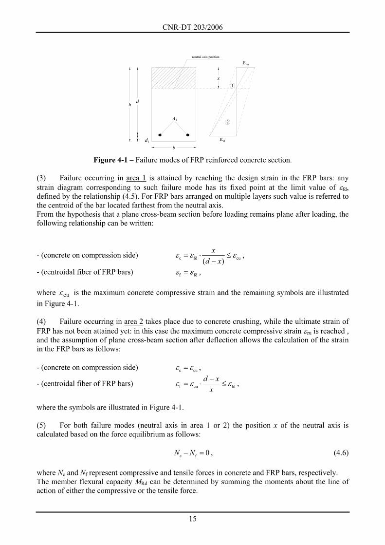
(2) With reference to the illustrative scheme shown in Figure 4-1, two types of failure may be
accounted for, depending upon whether the ultimate FRP strain (area 1) or the concrete ultimate
compressive strain (area 2) is reached.
CNR-DT 203/2006
15
d
d
h
1
b
A f
x
cu
fd
2
1
neutral axis position
Figure 4-1 – Failure modes of FRP reinforced concrete section.
(3) Failure occurring in area 1 is attained by reaching the design strain in the FRP bars: any
strain diagram corresponding to such failure mode has its fixed point at the limit value of fd,
defined by the relationship (4.5). For FRP bars arranged on multiple layers such value is referred to
the centroid of the bar located farthest from the neutral axis.
From the hypothesis that a plane cross-beam section before loading remains plane after loading, the
following relationship can be written:
- (concrete on compression side) c fd cu( )
x
d x,
- (centroidal fiber of FRP bars) f fd ,
where cu is the maximum concrete compressive strain and the remaining symbols are illustrated
in Figure 4-1.
(4) Failure occurring in area 2 takes place due to concrete crushing, while the ultimate strain of
FRP has not been attained yet: in this case the maximum concrete compressive strain cu is reached ,
and the assumption of plane cross-beam section after deflection allows the calculation of the strain
in the FRP bars as follows:
- (concrete on compression side) c cu ,
- (centroidal fiber of FRP bars) f cu fd
d x
x,
where the symbols are illustrated in Figure 4-1.
(5) For both failure modes (neutral axis in area 1 or 2) the position x of the neutral axis is
calculated based on the force equilibrium as follows:
c f0N N , (4.6)
where Nc and Nf represent compressive and tensile forces in concrete and FRP bars, respectively.
The member flexural capacity MRd can be determined by summing the moments about the line of
action of either the compressive or the tensile force.
CNR-DT 203/2006
16
(6) Due to the FRP bars having linear elastic behaviour up to failure, their stress may be
computed as the product of the pertaining strain by the FRP modulus of elasticity.
(7) According to the current building code, design at ULS can be conducted by assuming a
simplified distribution of the normal stresses for concrete (“stress block”), for elements whose
failure is initiated either by the crushing of concrete or rupture of the FRP bars.
4.7.2.3 Minimum reinforcement
(1) The amount of longitudinal FRP reinforcement in tension shall not be less than the
minimum value that satisfies the following equation:
MRd = 1.5 · Mcr , (4.7)
where Mcr is the the cracking moment to be determined according to the current building code.
(2) For elements that do not require shear reinforcement, sufficient longitudinal FRP
reinforcement in tension shall be provided such that l f /( ) 0.01A b d .
4.7.3 Service limit state analysis
4.7.3.1 Design assumptions
(1)P The present section deals with the most frequent service limit states, and particularly those
relating to:
Stress limitation (Section 4.7.3.2);
Deflection control (Section 4.7.3.3);
Cracking control (Section 4.7.3.4).
Other service limit states may be relevant in particular situations, even though they are not listed in
this Document.
(2)P The following items shall be checked at SLS:
The stress level in all materials is properly limited in order to avoid FRP bars rupture under
continuous stress as well as to mitigate creep phenomena in the concrete;
Both deformations and deflections do not attain excessive values, so as to inhibit the normal
use of the structure, induce damage to non supporting elements, and cause psychological
disturbances to the users;
Cracking phenomena are properly limited to not significantly affect the durability of the
structures, their functionality, their aspect, and damage the integrity of the adhesive bond at
the FRP-concrete interface.
(3)P Safety checks at SLS can be carried out in the linear-elastic range, by taking into account
both the behaviour of the uncracked or cracked transformed section. The stress in the materials can
be evaluated by the superposition principle.
The design hypotheses are as follows:
Linear elastic behaviour of materials;
Plane cross-beam sections before loading remains plane after loading;
CNR-DT 203/2006
17
Perfect bond exists between the concrete and FRP bars.
(4)P The first hypothesis implies the assumption of a constant Young’s modulus of elasticity (in
the direction of the beam axis) for each material; the second implies the linearity of the strain
diagram; the third, coupled with the first, allows a proportionality ratio between the stress in the
FRP reinforcement and that in a concrete fiber bonded to it ( f/ c=Ef/Ec=nf).
Such ratio is called modular ratio of the FRP reinforcement with respect to concrete. It represents
the stress diagram on FRP reinforced elements as a concrete transformed cross section, provided
that the FRP is magnified by the coefficient fn .
The value of fn shall be set accounting for the evolution of creep for both short and long-term
situations.
(5)P The position of the neutral axis and the moment of inertia of both uncracked and cracked
transformed cross-beam sections shall be evaluated for safety checks at SLS.
(6)P In addition to applied loads, when computing stresses at SLS the effects of thermal
variation, creep and shrinkage shall be accounted for.
4.7.3.2 Stress limitation
(1)P The stress in the FRP reinforcement at SLS under the quasi-permanent load shall satisfy the
limitation f fdf , ffd being the FRP design stress at SLS computed by setting f = 1 with the
values of reported in Section 4.6.
Stress in the concrete shall be limited according to the current building code.
4.7.3.3 Deflection control
(1)P Deflections exhibited by FRP reinforced structures shall comply with current building code
requirements.
(2)P The adopted deflection model shall simulate the real behaviour of the structure. If deemed
necessary, cracking shall be accounted for.
(3)P The adopted deflection model shall take into account the following:
Appropriate concrete Young’s modulus of elasticity depending upon concrete curing at the
time of loading;
Creep and shrinkage of concrete;
Concrete stiffening between cracks;
Thermal loads;
Static and/or dynamic loads.
(4)P The superposition principle shall not be applied if deflections are computed using non-linear
analysis.
(5) Deflection computation for FRP reinforced members can be performed by integration of the
curvature diagram. Such diagram can be computed with non-linear analyses by taking into account
both cracking and tension stiffening of concrete. Alternatively, simplified analyses are possible,
similar to those used for traditional RC members. Experimental tests have shown that the model
proposed by Eurocode 2 (EC2) when using traditional reinforced concrete members can be deemed
CNR-DT 203/2006
18
suitable for FRP reinforced concrete elements too. Therefore, the following EC2 equation to
compute the deflection f can be considered:
m m
cr cr1 1 2 2 1 2
max max
1M M
f f fM M
(4.8)
where:
- 1f is the deflection of the uncracked section;
- 2f is the deflection of the transformed cracked section;
- 1 0 5. is a non-dimensional coefficient accounting for bond properties of FRP bars;
- 2 is a non-dimensional coefficient accounting for the duration of loading (1.0 for short time
loads, 0.5 for long time or cyclic loads);
- maxM is the maximum moment acting on the examined element;
- crM is the cracking moment calculated at the same cross section of maxM ;
- m is a coefficient to be set equal to 2.
4.7.3.4 Crack control
(1)P At SLS, crack width shall be checked in order to guarantee a proper use of the structure as
well as to protect the FRP reinforcement.
(2) It is recommended to consider only permanent loading for crack control.
(3)P Under no circumstances crack width of FRP reinforced structures shall be higher than 0.5
mm.
(4)P Experimental tests on FRP reinforced members (with the exception of smooth bars) showed
the suitability of the relationships provided by the EC2 for computation of both distance between
cracks and concrete stiffening.
The following equation can be used:
k rm fmw s , (4.9)
where:
- kw is the characteristic crack width, in mm;
- is a coefficient relating average crack width to the characteristic value, to be set equal to:
i) 1.7 for cracking due to loads;
ii) 1.7 for restrained cracking in cross sections with a minimum dimension (depth, width or
thickness, whichever is the least) higher than 800 mm.
CNR-DT 203/2006
19
iii) 1.3 for restrained cracking in cross sections with a minimum dimension (depth, width or
thickness, whichever is the least) less than 300 mm.
iv) a linearly interpolated value between 1.3 and 1.7 for restrained cracking in sections with a
minimum dimension ranging between 300 mm and 800 mm.
- rms is the final average distance between cracks, in mm;
- fm is the average strain accounting for tension stiffening, shrinkage, etc.
(5) The final average distance between cracks can be computed using the following equation:
brm 1 2
r
50 0 25d
s . k k , (4.10)
where:
- 1k is a coefficient accounting for the bond properties of the FRP bars, to be set equal to 1.6;
- 2k is a coefficient depending upon the strain diagram (0.5 for flexure, 1.0 for pure tension);
- bd is the equivalent diameter of the FRP bars, in mm; if bars of different diameter are used, their
average value can be considered;
- r is the effective reinforcement ratio, equal to f c,effA / A , where c,effA is the effective area in
tension defined as the concrete area surrounding the tensile FRP reinforcement, having depth equal
to 2.5 times the distance between tension fiber and bars centroid (EC2).
(6) fm can be derived using the following equation:
m
f frfm 1 2
f f
1E
, (4.11)
where:
- f is the reinforcement stress in tension of the cracked cross section;
- 1 e 2 are coefficients defined in Section 4.7.3.3;
- fr is the reinforcement stress in tension of the cracked cross section when the first crack is
observed;
- m is a coefficient to be set equal to 2.
(7) A specific bond characterization of FRP bars for the investigation of crack control is
reported in Appendix E to determine both m and 1k .
CNR-DT 203/2006
20
4.8 SHEAR
4.8.1 Introduction
(1) This document refers to shear reinforcement made of FRP stirrups perpendicular to the axis
of the element.
(2)P Shear verifications of FRP reinforced concrete members shall be carried out at ULS only.
4.8.2 Basis for design
4.8.2.1 Members without shear reinforcement
(1) Design of slabs, plates, or frames without stirrups is permitted provided that proper
transversal distribution of loads is allowed.
(2) Shear capacity of FRP reinforced members without stirrups can be evaluated as follows:
Rd Rd,ct Rd,maxminV V ,V , (4.12)
where Rd,ctV represents the concrete contribution to shear capacity, and Rd,maxV is the concrete
contribution corresponding to shear failure due to crashing of the web, as reported by the current
building code.
(3) Rd,ctV can be computed as follows:
1/ 2
fRd,ct Rd 1
s
1.3 1.2 40E
V k b dE
, (4.13)
satisfying the limitation
1/ 2
f
s
1.3 1E
E.
The following symbols have been introduced in the equation (4.13):
- Ef and Es, which represent the Young’s moduli of elasticity of the FRP and steel bars (N/mm2),
respectively;
- Rd , which is defined the design shear stress (N/mm2), defined as: Rd ctd0.25 f ;
- k , which represents a coefficient to be set equal to 1 for members where more than 50 % of the
bottom reinforcement is interrupted; if this is not the case, k shall be assumed as (1.6 ) 1d ,
where d is in m;
- the parameter l f /( )A b d , which shall not be assumed larger than 0.02.
4.8.2.2 Elements with shear reinforcement
(1) Shear capacity of FRP reinforced elements using FRP stirrups can be computed using the
following equation:
CNR-DT 203/2006
21
Rd Rd,ct Rd,f Rd,maxminV V V ,V ,
where Rd,ctV and Rd,maxV have been introduced in Section 4.8.2.1, and Rd,fV is the FRP contribution to
the shear capacity, to be evaluated as defined hereafter.
(2) Rd,fV can be calculated as follows:
fw frRd,f
A f dV
s, (4.14)
where Afw is the amount of FRP shear reinforcement within stirrups spacing s (sum of the area of
single stirrup legs), and frf is the reduced tensile strength of the FRP reinforcement, defined as
fd f,f .
The partial factor f, , which further reduces the design tensile strength of FRP reinforcement to
account for the bending effect, shall be set equal to:
- 2 when no specific experimental tests are performed, provided that the bend radius is not
less than six times the equivalent diameter, bd ;
- the ratio of the straight FRP bar strength to the bent FRP design strength, in all other cases
(see Section 4.11).
4.8.3 Minimum shear reinforcement
(1) Where shear reinforcement is required, the minimum area of shear reinforcement shall be
computed as follows:
2
fw,min ck
f
0.06 [stresses in N/mm ]0.004
b sA f
E, (4.15)
but shall not be less than f(0.35 ) 0.004b s E .
4.9 SECONDARY FRP REINFORCEMENT
(1) For slabs and other two-dimensional elements calculated using a one-way approach, only
primary FRP reinforcement to be placed in the main direction can be calculated. Secondary FRP
reinforcement of not less than 20% of the primary reinforcement shall be placed perpendicular to
the primary reinforcement.
4.10 DEVELOPMENT LENGTH
(1) The development length of FRP reinforcement shall not be less than the following:
d f b0 1 [forces in N, lengths in mm]l . d , (4.16)
nor 400 mm.
In Equation (4.16) f and bd are the stress of the FRP bar at the end anchorage cross section and
the equivalent diameter bar, respectively.
CNR-DT 203/2006
22
The possibility of a suitable shifting of the bending moment diagram close to the support zone,
where the shear forces may induce inclined cracking, shall be taken into account in the evaluation
of stress f .
(2) Anchoring and lap splice of smooth FRP bars in tension is not allowed. Anchoring and lap
splice of smooth FRP bars in compression can be computed as twice the value provided by the
equation (4.16).
4.11 CONSTRUCTION DETAILS
(1) In addition to Section 4 item (2)P, a minimum amount of FRP reinforcement equal to: 0.3 %
of the concrete area for columns reinforced with carbon FRP bars; 1.5 % of the concrete area for
columns reinforced with glass FRP bars; 0.8 % of the concrete area for columns reinforced with
aramid FRP bars, shall be provided.
(2) To limit the stress concentration at the bent portion of the FRP bars, the radius of the bend
shall not be less than 6 bd .
The use of lower values of the bend radius is allowed provided that:
- The manufacturer performs experimental tests (ACI 440.3R-04) in order to determine the
characteristic strength of the bent portion of the specimen;
- The value of partial factor f, to use for computation of frf shall be derived according to
item (2) of Section 4.8.2.2.
(3) According to Section 3.2.3 item (4) the concrete cover ds shall be determined as
recommended in the current building code for traditional steel reinforced concrete structures. In
addition, ds shall satisfy the following limitations:
S
25 mm (two-ways slabs)
30 mm (one-ways slabs)
35 mm (columns)
d (4.17)
The threshold ds shall be increased by 20% for concrete with Rck < 25 N/mm2.
(4) FRP reinforced concrete beams shall have at least three stirrups per meter and in no case
shall be s 0.8 d (s = stirrup spacing).
At connections of principal framing elements (such as beams and columns) and at the location of
concentrated loads, for a distance equal to the effective depth of the cross section, stirrup spacing
shall not exceed the least among the following:
- 4d ,
- 12 times the minimum equivalent diameter of longitudinal FRP reinforcement;
- 15 cm.
(5) Spacing of shear reinforcement in columns shall not exceed 15 times the minimum FRP bar
diameter used in the longitudinal direction, nor 25 cm.
Stirrups spacing shall be decreased at column edges for a length not less than the following:
- the larger dimension of the cross section;

CNR-DT 203/2006
23
- 1 6 of net column height (1 3 of net column height for isostatic columns);
- 45 cm.
Along column edges the distance between stirrups shall not exceed the lesser between the
following:
- 1 6 of minimum dimension of the cross section;
- 15 cm.
CNR-DT 203/2006
24
5 APPENDIX A (MANUFACTURING TECHNIQUES OF FRP BARS AND GRIDS)
5.1 FRP BARS
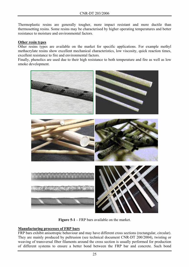
FRP bars are available on the market as reinforcement for concrete structures (Figure 5-1). They are
made of glass fibers (GFRP), carbon fibers (CFRP) or aramid fibers (AFRP), embedded in
thermoset or thermoplastic resins. The use of the last ones is not included in the present document.
In this guide, the main characteristics of resins are reported, whereas fibers characteristics are
detailed in the technical document CNR-DT 200/2004.
FRP bars properties, such as high temperature performances, corrosion resistance, dielectric
properties, flammability and thermal conductivity are mainly derived from the properties of their
components.
Unsaturated polyester resins
The basic components of unsaturated polyester resins are made of orthophthalic acids, isophthalic
acids or anhydrides, mixed with maleic anhydride and different glycols. Polyester resins shall have
gelling and quick hardening capability. Resins with a viscosity of 100 mPas are used in pultrusion.
Monomers with larger viscosity and lower reactivity can be mixed with styrene to aid the
manufacturing process. Styrene level shall be such that proper reticulation without styrene residuals
will occur in the composite.
Polyester resins exhibit good resistance to corrosion with respect to aliphatic hydrocarbons, water,
and acid environment. They do not exhibit good resistance to aromatic hydrocarbons, ketones and
concentrated acids and alkali. Highly unsaturated polyester chains can cause shrinkage up to 7%
during the curing process. This can be reduced by using fillers or additives. Polyester resins show
good electrical insulation and fire resistance, with bromide process or additives reducing even
further flammability and smoke development.
Vinyl ester resins
Vinyl ester resins show better resistance to both corrosion and penetration of moisture, and they
have good mechanical properties at elevated temperatures. They also have good resistance to
interlaminar shear and impact. Their chemical structure promotes reactions at the edges of
polymeric chains rather than along the chain itself, thus resulting in a stiffer internal framework.
This implies lower connection density and resistance to higher temperatures.
Epoxy resins
Epoxy resins show good resistance to both moisture and chemical agents and they have good
adhesive properties. They are used mainly due to their good mechanical properties, excellent
electric properties, corrosion resistance and performances at elevated temperatures, up to 150°C.
Epoxy resins show higher flexure and shear capacity than polyester and vinyl ester resins. They
need longer curing time, therefore affecting the efficiency of the pultrusion process.
Thermoplastic resins
Composite bars using thermoplastic resins are currently being studied as they can be bent through
thermal treatment even after the manufacturing process. Such resins have the capability of flowing
after heating at a temperature higher than the glass transition temperature for amorphous materials,
and higher than the melting temperature for semi-crystalline materials. The shape of each
component may be modified by simply heating the material at a suitable temperature (hot forming).
CNR-DT 203/2006
25
Thermoplastic resins are generally tougher, more impact resistant and more ductile than
thermosetting resins. Some resins may be characterised by higher operating temperatures and better
resistance to moisture and environmental factors.
Other resin types
Other resins types are available on the market for specific applications. For example methyl
methacrylate resins show excellent mechanical characteristics, low viscosity, quick reaction times,
excellent resistance to fire and environmental factors.
Finally, phenolics are used due to their high resistance to both temperature and fire as well as low
smoke development.
Figure 5-1 – FRP bars available on the market.
Manufacturing processes of FRP bars
FRP bars exhibit anisotropic behaviour and may have different cross sections (rectangular, circular).
They are mainly produced by pultrusion (see technical document CNR-DT 200/2004), twisting or
weaving of transversal fiber filaments around the cross section is usually performed for production
of different systems to ensure a better bond between the FRP bar and concrete. Such bond
CNR-DT 203/2006
26
properties are typically made by helical-wrapping of fiber filaments around the cross section,
frosting of bar surfaces or pure resin molding.
Wrapping of transversal fiber filaments around the cross section is very significant for the shear
behavior of the FRP bars, which show a low resistance to interlaminar shear mainly governed by
the polymeric matrix. Filaments are applied after the pultrusion process. An alternative technology
using layers of mat (fabric made of short fibers randomly oriented) allows transversally reinforcing
the bar during the pultrusion process.
In relation to steel reinforcement, FRP bars show limited applicability due to the bending
difficulties when producing either stirrups or shaped pieces. Such elements can be manufactured
through molding in specific machineries, but only limited shapes and dimensions can be performed
at higher cost. FRP bars are currently used as straight bars or grids to build slabs, walls and
diaphragms. The use of thermoplastic resins is likely to solve the aforementioned drawbacks,
making FRP bars competitive with metallic bars.
Factors such as volume and fibers orientation, fibers and resins nature, dimensional effects and
quality control during manufacturing play an important role in determining the properties of FRP
bars.
5.2 FRP GRIDS
FRP grids are characterised by specific physical and mechanical properties: lightness, high strength
and corrosion resistance.
These grids are generally adopted, either in place of or in addition to traditional reinforcement (steel
bars and welded grids) for the construction of reinforced concrete elements.
A further advantage of the use of FRP grids over steel ones is represented by the possibility of being
positioned closer to structural element extrados, since there is no need for a concrete cover against
corrosion phenomena.
The use of FRP grids in structural elements may reduce the concrete cracking.
FRP grids are supplied on market in rolls and are characterised by fixed grid spacing and its cross
sectional area.
CNR-DT 203/2006
27
6 APPENDIX B (TEST METHODS FOR CHARACTERISING FRP BARS)
This Appendix includes the test methods for determining the geometric and mechanical properties
of FRP bars, as proposed by the ACI Committee 440 in the document entitled “Guide Test Methods
for Fiber-Reinforced Polymers (FRPs) for Reinforcing or Strengthening Concrete Structures”
(2004).
6.1 METHOD FOR CALCULATING THE GEOMETRIC PROPERTIES
The following test method described is intended to determine the equivalent cross sectional area of
an FRP bar.
At least five bar specimens, approximately 200 mm long, shall be used. The specimens shall be
conditioned prior to test in accordance to procedure A of ASTM D 618 standard.
This procedure requires that the specimen bars with a diameter of approximately 7 mm or less are
conditioned for 40 hours at 23°C with 50% relative humidity whereas those bars with a diameter
greater than 7 mm shall be conditioned for 88 hours under the same conditions.
The tests shall be carried out under standard environmental conditions (at 23 3 °C and 50 10 %
relative humidity) with the specimens being kept in the test environment for at least 24 hours prior
to testing.
The tests consists of immersing the specimen bars in a graduated cylinder filled with either water,
or ethanol if air bubbles are present on the specimen surface, and then once the bars are fully
immersed, measuring the volume increase of the liquid.
The cylinder used shall be of an appropriate height in order to contain the whole bar as well as
ensure that there will be no overflow once the specimen is immersed. It shall also be graduated
with a maximum gradient of 10 ml.
In order to determine the equivalent cross sectional area of the tested specimen, Ap, its average
length, lp, shall be determined. The latter is assumed to be equal to the average value of the three
specimen lengths, measured rotating the bar by 120° for each measure. The measurement shall be
carried out using callipers with a precision of 0.025 mm.
Once the average length of the single specimen, lp, has been calculated, its equivalent cross
sectional area can be evaluated using the following expression:
1 0p
p
V VA
l, (6.1)
where V0 and V1 are the volume in the cylinder before and after immersing the bar, respectively.
Once all the equivalent cross sectional areas of the specimens have been determined, the average
value of these quantities, Ab, which characterises the geometry of the bar, may be evaluated. The
corresponding diameter is indicated using db.
6.2 METHOD FOR CALCULATING THE MECHANICAL PROPERTIES
This section describes the test method intended to determine the mechanical properties of a
composite bar. The test conditions are the same for the aforementioned test, with standard
environmental conditions (at 23 3 °C and 50 10 % relative humidity). At least five FRP specimen
bars are also required for this test, conditioned according to procedure A of the ASTM 618 (see
Section 6.1). The bars must be kept in the test environment for at least 24 hours prior to testing.
The length of the specimens to be tested, lp, shall be in compliance with the following requirements:
CNR-DT 203/2006
28
p a
p b a
100 + 2 [length in mm],
40 + 2 ,
l l
l d l (6.2)
considering that la and db, are the length of the anchorage and the bar diameter, respectively, with
the latter being calculated according to Section 6.1.
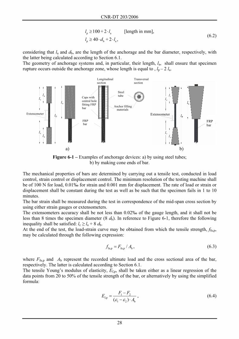
The geometry of anchorage systems and, in particular, their length, la, shall ensure that specimen
rupture occurs outside the anchorage zone, whose length is equal to , lp – 2 la.
l
l
l
l
FRP
a
Longitudinal
section
Transversal
section
Steel
tube
materialsAnchor filling
bar
Caps with
central hole
fitting FRP
bar
a
a
pExtensometer
lc
lc
FRP bar
Extensometer
a) b)
Figure 6-1 – Examples of anchorage devices: a) by using steel tubes;
b) by making cone ends of bar.
The mechanical properties of bars are determined by carrying out a tensile test, conducted in load
control, strain control or displacement control. The minimum resolution of the testing machine shall
be of 100 N for load, 0.01‰ for strain and 0.001 mm for displacement. The rate of load or strain or
displacement shall be constant during the test as well as be such that the specimen fails in 1 to 10
minutes.
The bar strain shall be measured during the test in correspondence of the mid-span cross section by
using either strain gauges or extensometers.
The extensometers accuracy shall be not less than 0.02‰ of the gauge length, and it shall not be
less than 8 times the specimen diameter (8 db). In reference to Figure 6-1, therefore the following
inequality shall be satisfied: lc la + 8 db.
At the end of the test, the load-strain curve may be obtained from which the tensile strength, ffu,p,
may be calculated through the following expression:
fu,p fu,p b/f F A , (6.3)
where Ffu,p and Ab represent the recorded ultimate load and the cross sectional area of the bar,
respectively. The latter is calculated according to Section 6.1.
The tensile Young’s modulus of elasticity, Ef,p, shall be taken either as a linear regression of the
data points from 20 to 50% of the tensile strength of the bar, or alternatively by using the simplified
formula:
1 2f,p
1 2 b( )
F FE
A, (6.4)
CNR-DT 203/2006
29
where F1 and 1 are the load and corresponding strain, respectively, at approximately 50% of the
ultimate tensile capacity, while F2 and 2, are the load and corresponding strain, respectively, at
approximately 20% of the ultimate tensile capacity.
The ultimate strain of the specimen bars, fu,p, shall be calculated with the following expression:
fu,p
fu,p
f,p b
F
E A. (6.5)
Once the mechanical properties of the specimens have been determined, the characteristic values of
these properties of the FRP bar may be determined according to Section 4.4.3.
CNR-DT 203/2006
30
7 APPENDIX C
7.1 TECHNICAL DATA SHEET FOR FRP BARS
(1) An example of a standard technical data sheet for FRP bars is proposed in the following
section. It presents analogies with the data sheet proposed in the CNR-DT 200/2004 document for
pre-cured systems used in external strengthening of existing structures. Technical data sheets of
FRP bars available on the market can also include other information or report only a portion of
those here indicated. The proposed structure is exhaustive regarding the type and amount of
information given.
TECHNICAL DATA SHEET: FRP bars for reinforced concrete structures
THE MANUFACTURER SHALL REPORT THE STATISTICAL VALUES NEEDED FOR THE
EVALUATION OF THE CHARACTERISTIC STRENGTHS (E.G. SAMPLE MEAN, STANDARD
DEVIATION, POPULATION, PERCENTILE, CONFIDENCE INTERVAL).
Description
Commercial name, type of fiber, type of resin, manufacturing technology and any other information
deemed useful
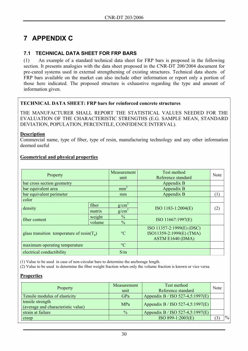
Geometrical and physical properties
Property Measurement
unit
Test method
Reference standard Note
bar cross section geometry Appendix B
bar equivalent area mm2 Appendix B
bar equivalent perimeter mm Appendix B (1)
color
fiber g/cm3
densitymatrix g/cm3 ISO 1183-1:2004(E) (2)
weight %fiber content
volume %ISO 11667:1997(E)
glass transition temperature of resin(Tg) °C
ISO 11357-2:1999(E) (DSC)
ISO11359-2:1999(E) (TMA)
ASTM E1640 (DMA)
maximum operating temperature °C
electrical conductibility S/m
(1) Value to be used in case of non-circular bars to determine the anchorage length.
(2) Value to be used to determine the fiber weight fraction when only the volume fraction is known or vice versa.
Properties
Property Measurement
unit
Test method
Reference standard Note
Tensile modulus of elasticity GPa Appendix B / ISO 527-4,5:1997(E)
tensile strength
(average and characteristic value) MPa Appendix B / ISO 527-4,5:1997(E)
strain at failure % Appendix B / ISO 527-4,5:1997(E)
creep ISO 899-1:2003(E) (3) %
CNR-DT 203/2006
31
relaxation (bars, cables) (4)
bond: tangential stress (bars, cables) pull-out test (4)
(3) The ISO 899-1:2003(E) standard is the general reference standard for creep behaviour of FRP materials, while the ISO
standard (TC71/SC6N) “Non-conventional strengthening of concrete - Test methods-Part 1: Fiber strengthened polymer
(FRP) bars and grids” is under way for reinforcing FRP bars and prestressed grids, where a specific test is proposed for FRP
bars (“Test Method for creep failure”). As an alternative, there is a test proposed in the document ACI 440.3R-04 “Guide
Test Methods for Fiber-reinforced Polymers for Reinforcing or Strengthening Concrete Structures” named “Test Method for
creep rupture of FRP bars”.
(4) In the ISO standard (TC71/SC6N) concerning FRP bars and grids the following two tests are proposed: “Test method for
bond strength by pull-out testing” for bond, and “Test Method for long-term relaxation” for relaxation. Similar tests are
included in the ACI 440.3R-04 document.
Storage Conditions
Description
Safety and handling
Description
CNR-DT 203/2006
32
8 APPENDIX D
8.1 SELECTION AND TESTING OF FRP BARS: TASKS AND RESPONSIBILITIES OF PROFESSIONALS
Manufacturers:
Production of FRP bars as well as that of single phase (fibers and matrix) shall be subjected
to a quality control program including fibers, matrices, adhesives, pre-cured composites and
other constituents.
Manufacturers shall provide test certificates for each production lot in compliance with their
published literature.
Whenever possible, each production lot shall be marked to ensure traceability. If this is not
the case, each lot shall be accompanied by labels or tags reporting all the information needed
for their traceability.
Designer:
Designers shall clearly state the quality and characteristics (geometrical, mechanical, and
physical) of FRP bars, specifying, if necessary, the minimum acceptance requirements.
Designers shall specify the acceptance criteria for FRP bars, informing the construction
manager of the samples to be taken and the tests to be carried out. For example, depending
on the relevance of the application, designers could suggest to carry out some tests to check
some or all of the mechanical and physical characteristics reported by the manufacturer in
the technical data sheets.
Contractor/subcontractors:
Shall obtain the FRP bars indicated by the designer through suppliers/manufacturers who
guarantee the quality of their products.
Shall make sure that the products are accompanied by suitable technical data sheets,
reporting both mechanical and physical characteristics, and possibly by laboratory test
certificates.
Shall make sure that the products comply with the provisions indicated by the designer; if
the material with the indicated requirements is not available, they shall agree with the
designer upon viable alternatives.
Construction manager:
Shall make decisions as to the acceptance of products.
Shall check the compliance of the material with the designer’s provisions.
Shall check the origin of the supplied material. FRP bars are typically marked by the
manufacturer for their identification or they have labels or tags with the necessary
information for their traceability.
Shall check the mechanical and physical characteristics of products using the test certificates
provided by the manufacturer.
Based upon the importance of the application, it may require experimental tests to evaluate
both quality of materials and compliance with the values provided by the manufacturer.
Such tests shall be carried out in laboratories of proven experience that are appropriately
equipped to characterize FRP materials. Acceptance criteria may be based on the maximum
acceptable deviation of results from the values obtained during production. In such a case, it
is necessary to ensure that the test procedures are the same. In some cases, tests may be
required to evaluate both mechanical and physical properties of un-conditioned and
conditioned specimens to take into account temperature and moisture variation.
CNR-DT 203/2006
33
Test laboratories:
Shall demonstrate experience in the experimental characterization of FRP materials.
Shall be equipped with appropriate measurement devices and tests instrumentation.
Shall carry out the experimental tests according to the procedures indicated in the specific
standards for FRP bars.
Shall provide detailed test reports on test instrumentation and results.
Shall own a quality manual and carry out experimental activities according to EN-ISO17025
“General requirements for the competence of testing and calibration laboratories”.
Inspector:
Check the quality of the materials to be in compliance with the manufacturer specifications.
Verify that all materials used have been accepted by the construction manager.
Check the results of experimental tests required by the construction manager, if available.
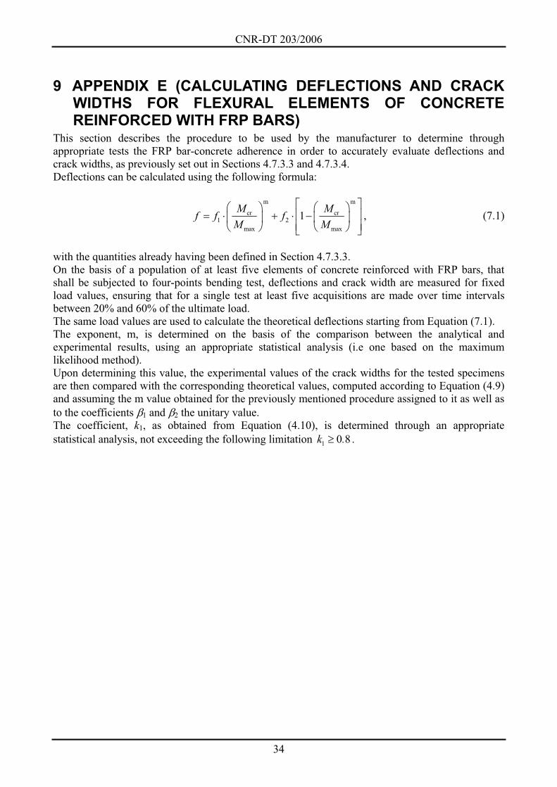
CNR-DT 203/2006
34
9 APPENDIX E (CALCULATING DEFLECTIONS AND CRACK WIDTHS FOR FLEXURAL ELEMENTS OF CONCRETE REINFORCED WITH FRP BARS)
This section describes the procedure to be used by the manufacturer to determine through
appropriate tests the FRP bar-concrete adherence in order to accurately evaluate deflections and
crack widths, as previously set out in Sections 4.7.3.3 and 4.7.3.4.
Deflections can be calculated using the following formula:
m m
cr cr1 2
max max
1M M
f f fM M
, (7.1)
with the quantities already having been defined in Section 4.7.3.3.
On the basis of a population of at least five elements of concrete reinforced with FRP bars, that
shall be subjected to four-points bending test, deflections and crack width are measured for fixed
load values, ensuring that for a single test at least five acquisitions are made over time intervals
between 20% and 60% of the ultimate load.
The same load values are used to calculate the theoretical deflections starting from Equation (7.1).
The exponent, m, is determined on the basis of the comparison between the analytical and
experimental results, using an appropriate statistical analysis (i.e one based on the maximum
likelihood method).
Upon determining this value, the experimental values of the crack widths for the tested specimens
are then compared with the corresponding theoretical values, computed according to Equation (4.9)
and assuming the m value obtained for the previously mentioned procedure assigned to it as well as
to the coefficients 1 and 2 the unitary value.
The coefficient, k1, as obtained from Equation (4.10), is determined through an appropriate
statistical analysis, not exceeding the following limitation 1 0 8k . .

CNR-DT 203/2006
35
10 ACKNOWLEDGEMENTS This document has been translated verbatim from Italian with the support of Department of Civil
Engineering of University of Salerno (DICIV) and the Center of Excellence on Structural
Composites for Innovative Construction (SCIC).
The translation has been carried out by the members of the Task Group under the supervision of
Raffaello Fico, Renato Parretti, Andrea Prota (SCIC) and Valentino Paolo Berardi (DICIV), whose
contribution is gratefully acknowledged.
The members of the Task Group thank all the practitioners, industries, and academia that have
worked in order to achieve the general consensus on the present document.