Embed Size (px)
Citation preview
GUIDE FOR THE
CERTIFICATION OF DRILLING SYSTEMS
JANUARY 2004
American Bureau of Shipping Incorporated by Act of Legislature of the State of New York 1862
Copyright 2004 American Bureau of Shipping ABS Plaza 16855 Northchase Drive Houston, TX 77060 USA

This Page Intentionally Left Blank
ABS GUIDE FOR THE CERTIFICATION OF DRILLING SYSTEMS . 2004 iii
Foreword
This Guide has been revised to assist the industry with Certification of Drilling Systems. The Guide describes criteria to be used for drilling systems, which are to be certified by American Bureau of Shipping (ABS), and it is built upon requirements of the American Petroleum Institute (API). The Guide contains the following nine main sections:
1 Scope and Condition of Classification
2 Design of Drilling Systems
3 Drilling Systems
4 Drilling System Certification Process
5 Drilling System Piping
6 Materials for Drilling Systems and Components
7 Welding and Nondestructive Examination
8 Surveys at Vendor’s Plant and at Installation
9 Surveys After Construction and Maintenance of Class
This Guide is to be used in conjunction with other Rules and Guides published by ABS and recognized Industrial Standards.
ABS certification continues to provide the offshore industry with a pathway toward agreement by Regulatory Authorities. However, the Owner’s specific request for compliance with applicable requirements of Flag or Coastal State Authorities affecting the drilling systems is to be filed as an addendum to the Request for Classification.

This Page Intentionally Left Blank
ABS GUIDE FOR THE CERTIFICATION OF DRILLING SYSTEMS . 2004 1
GUIDE FOR THE
CERTIFICATION OF DRILLING SYSTEMS
CONTENTS SECTION 1 Scope and Conditions of Classification ..............................7
1 Classification..........................................................................7 1.1 Process ............................................................................. 7 1.3 Certificates and Reports.................................................... 7 1.5 Representations as to Classification ................................. 8 1.7 Scope of Classification...................................................... 8
3 Suspension and Cancellation of Class ..................................9 3.1 Termination of Classification ............................................. 9 3.3 Notice of Surveys .............................................................. 9 3.5 Special Notations .............................................................. 9 3.7 Suspension of Class ......................................................... 9 3.9 Lifting of Suspension....................................................... 10 3.11 Cancellation of Class ...................................................... 10
5 Notations..............................................................................10 5.1 ABS Class Notation......................................................... 10 5.3 Systems Not Built Under Survey..................................... 10
7 Rules for Classification ........................................................11 7.1 Applications..................................................................... 11 7.3 Scope.............................................................................. 11 7.5 Alternatives ..................................................................... 11 7.7 ABS Type Approval Program .......................................... 12 7.9 Novel Features................................................................ 14 7.11 Risk Evaluations for Alternative Arrangements and
Novel Features................................................................ 15 7.13 Effective Date of Change of Requirement....................... 15
9 Other Regulations ................................................................15 9.1 International and Other Regulations................................ 15 9.3 Governmental Regulations.............................................. 16
11 IACS Audit ...........................................................................16 13 Submission of Plans ............................................................16 15 Conditions for Survey After Construction.............................16
15.1 Damage, Failure and Repair ........................................... 16 15.3 Notification and Availability for Survey ............................ 17
2 ABS GUIDE FOR THE CERTIFICATION OF DRILLING SYSTEMS . 2004
17 Units .....................................................................................17 19 Fees .....................................................................................17 21 Disagreement.......................................................................18
21.1 Rules and Guides............................................................18 21.3 Surveyor ..........................................................................18
23 Limitation of Liability.............................................................18 25 References...........................................................................18
SECTION 2 Design of Drilling Systems ................................................. 21
1 Drilling System Basics .........................................................21 1.1 General............................................................................21 1.3 Equipment Layout ...........................................................21 1.5 Overpressurization Protection .........................................21 1.7 Materials..........................................................................21 1.9 Welding and Nondestructive Examination .......................21
3 Design Specifications...........................................................22 5 Design Considerations.........................................................22
5.1 Recognized Standards ....................................................22 5.3 Alternative Basis of Design..............................................22 5.7 Corrosion/Erosion Allowance ..........................................22 5.9 Operating Conditions.......................................................23
7 Design Plans and Data ........................................................23 7.1 Systems...........................................................................23 7.3 Piping Design Documentation .........................................24 7.5 Derrick Documentation....................................................25 7.7 Burner/Flare Booms ........................................................25 7.9 Electrical Systems ...........................................................26 7.11 Instrumentation and Control Systems .............................26 7.13 Equipment Documentation ..............................................26
9 Risk Assessment .................................................................27 SECTION 3 Drilling Systems................................................................... 29
1 General ................................................................................29 3 Bulk Storage, Circulation and Transfer Systems.................29
3.1 Bulk Storage and Transfer Equipment ............................29 3.3 Cementing Equipment .....................................................29 3.5 Mud Return Equipment ...................................................30 3.7 Well Circulation Equipment .............................................30
5 Heave Compensation System .............................................31 5.1 Drill String Compensation Equipment..............................31 5.3 Tensioning Equipment.....................................................31 5.5 Motion Compensation and Tensioning System
Component Specific Requirements .................................31
7 Hoisting, Rotating and Pipe Handling System.....................31 7.1 Derricks/Masts.................................................................32 7.3 Hoisting Equipment .........................................................33
ABS GUIDE FOR THE CERTIFICATION OF DRILLING SYSTEMS . 2004 3
7.5 Miscellaneous Equipment ............................................... 38 7.7 Pipe Handling Equipment................................................ 39 7.9 Rotary Equipment ........................................................... 40
9 Marine Riser System............................................................40 9.1 Operating Envelope ........................................................ 41 9.3 Technical Requirements ................................................. 41 9.5 Design Documentation.................................................... 41 9.7 Testing ............................................................................ 42
11 Well Control System ............................................................42 11.1 Blow-out Preventer Equipment........................................ 42 11.3 Choke and Kill Equipment............................................... 44 11.5 Diverter Equipment ......................................................... 44
13 Well Test System.................................................................46 13.1 Burner/Flare Booms ........................................................ 46 13.3 Component Compliance.................................................. 46 13.5 Hydrocarbon Disposal Facilities ...................................... 47 13.7 Surface Safety Systems.................................................. 47 13.9 Classified Areas .............................................................. 47 13.11 Survey and Operations ................................................... 48
15 Control Systems...................................................................48 15.1 Control Safety ................................................................. 48 15.3 Logic Circuit Features ..................................................... 48
17 Pressure Retaining Components.........................................49 17.1 Pressure Vessels ............................................................ 49 17.3 Hydraulic Cylinders ......................................................... 49 17.5 High Pressure Hoses ...................................................... 49
19 Electrical Systems................................................................49 19.1 Rotating Machines .......................................................... 50
21 Internal Combustion Engines...............................................50 SECTION 4 Drilling System Certification Process ................................51
1 General ................................................................................51 3 Certification Process............................................................51
3.1 Manufacturer’s Affidavit................................................... 51 3.3 Design Review ................................................................ 51 3.5 ABS Survey..................................................................... 52
TABLE 1 Certification Codes for Drilling Systems ....................52
SECTION 5 Drilling System Piping .........................................................59
1 General ................................................................................59 3 Design Criteria .....................................................................59
3.1 Maximum Allowable Working Pressure (MAWP) and Minimum Thickness ........................................................ 59
3.3 Fittings, Valves, Connections.......................................... 60 3.5 Alternative Criteria........................................................... 60
4 ABS GUIDE FOR THE CERTIFICATION OF DRILLING SYSTEMS . 2004
3.7 Socket Welds ..................................................................60 3.9 Threaded Connections ....................................................60 3.11 Quick Connect Fittings ....................................................60 3.13 Flexible Hoses.................................................................60
5 Piping Materials ...................................................................61 SECTION 6 Materials for Drilling Systems and Components .............. 63
1 General ................................................................................63 3 Selection of Structural Steels...............................................63 5 Selection of Drilling Equipment Materials ............................63
5.1 Toughness.......................................................................63 5.3 Corrosion – Hydrogen Sulfide .........................................64 5.5 Corrosion – Marine Atmosphere......................................65 5.7 Stress ..............................................................................65
7 Fabrication Considerations ..................................................65 7.1 Welding ...........................................................................65 7.3 Forming ...........................................................................65
9 Primary Product Form..........................................................65 9.1 General............................................................................65 9.3 Rolled Products ...............................................................65 9.5 Forgings ..........................................................................65 9.7 Castings ..........................................................................66
11 Sealing Materials .................................................................66 11.1 Elastomeric Sealants.......................................................66 11.3 Ring Joint Gaskets ..........................................................66
13 Materials and Traceability ....................................................66 13.1 Materials..........................................................................66 13.3 Traceability ......................................................................66
FIGURE 1 Full Size Charpy V-Notch Specimens........................64
SECTION 7 Welding and Nondestructive Examination ........................ 67
1 General ................................................................................67 3 Specifications.......................................................................67
3.1 Welding Procedure Specification.....................................67 3.3 NDE Procedures .............................................................68
5 Welder/Welding Operator Qualification ...............................68 7 Qualification of Nondestructive Technicians........................68 9 Post Weld Heat Treatment...................................................68 11 Nondestructive Examination ................................................68
11.1 Extent of Examination for Materials and Welds ...............68 11.3 Methods and Acceptance Criteria ...................................69
13 Record Retention .................................................................70
ABS GUIDE FOR THE CERTIFICATION OF DRILLING SYSTEMS . 2004 5
SECTION 8 Surveys at Vendor’s Plant and During Installation...........71 1 General ................................................................................71 3 Surveys at Manufacture and During Assembly ...................71
3.1 Vendor Coordination Program ........................................ 72
5 Surveys During Installation Onboard...................................72 SECTION 9 Surveys After Construction and Maintenance of Class ...75
1 General ................................................................................75 3 Surveys Onshore and Issuance of Release Notes..............75 5 Survey of Drilling Systems...................................................75
5.1 Survey Intervals and Maintenance Manuals/Records ..... 75 5.3 Annual Surveys............................................................... 76 5.5 Special Periodical Surveys.............................................. 77 5.7 Continuous Survey Program ........................................... 77 5.9 Survey Based on Preventative Maintenance
Techniques ..................................................................... 77 5.11 Surveys Using Risk-based Techniques........................... 78
7 Modifications, Damage and Repairs....................................78 APPENDIX 1 Typical API Publications Related to ABS Certification
of Drilling Systems...............................................................79 APPENDIX 2 Sample Manufacturer’s Affidavit ........................................81 APPENDIX 3 Sample Release Note...........................................................83

This Page Intentionally Left Blank
ABS GUIDE FOR THE CERTIFICATION OF DRILLING SYSTEMS . 2004 7
S E C T I O N 1 Scope and Conditions of Classification
1 Classification
1.1 Process The term classification, as used herein, indicates that a drilling system and its equipment has been designed, constructed, installed and surveyed in compliance with the subject Guide, existing Rules and Guides or other acceptable standards.
The continuance of classification is dependent on the fulfillment of requirements for surveys after construction.
The classification process consists of:
a) The development of Rules, Guides, standards and other criteria for the design, construction, installation and maintenance of drilling systems and their equipment;
b) The review of the design and survey during and after construction to verify compliance with such Rules, Guides, standards or other criteria;
c) The assignment and registration of class when such compliance has been verified, and;
d) The issuance of a renewable Classification certificate, with annual endorsements, valid for five years.
The Rules, Guides and standards are developed by the Bureau staff and passed upon by committees made up of naval architects, ocean and marine engineers, shipbuilders, engine builders, steel makers, process engineers and by other technical, operating and scientific personnel associated with the worldwide maritime industry. Theoretical research and development, established engineering disciplines, as well as satisfactory service experience are utilized in their development and promulgation. The Bureau and its committees can act only upon such theoretical and practical considerations in developing Rules and standards.
For Classification, the drilling system and its equipment are to comply with the requirements of this Guide and all applicable Rules.
1.3 Certificates and Reports Review of design documentation and surveys during and after construction are conducted by the Bureau to verify to itself and its committees that an item of material, equipment or machinery is in compliance with this Guide and is to the satisfaction of the attending Surveyor. All reports and certificates are issued solely for the use of the Bureau, its committees, its clients and other authorized entities.
Section 1 Scope and Conditions of Classification
8 ABS GUIDE FOR THE CERTIFICATION OF DRILLING SYSTEMS . 2004
1.5 Representations as to Classification Classification is a representation by the Bureau as to the structural and mechanical fitness for a particular use or service, in accordance with its Rules, Guides and standards. The Rules and Guides of the American Bureau of Shipping are not meant as a substitute for the independent engineering judgment of professional designers, naval architects, marine engineers, owners, operators, masters and crew, nor as a substitute for the quality control procedures of ship and platform builders, engine builders, steel makers, suppliers, manufacturers and sellers of marine vessels, materials, system components, machinery or equipment. The Bureau, being a technical society, can only act through Surveyors or others who are believed by it to be skilled and competent.
The Bureau represents solely to the Drilling System Owner or other client of the Bureau that when assigning class, it will use due diligence in the development of Rules, Guides and Standards, and in using normally applied testing standards, procedures and techniques as called for by the Rules, Guides, standards or other criteria of the Bureau for the purpose of assigning and maintaining class. The Bureau further represents to the Owner or other Client of the Bureau that its certificates and reports evidence compliance only with one or more of the Rules, Guides, standards or other criteria of the Bureau, in accordance with the terms of such certificate or report. Under no circumstances whatsoever are these representations to be deemed to relate to any third party.
The user of this document is responsible for ensuring compliance with all applicable laws, regulations and other governmental directives and orders related to a vessel, its machinery and equipment, or their operation. Nothing contained in any Rule, Guide, standard, certificate or report issued by the Bureau shall be deemed to relieve any other entity of its duty or responsibility to comply with all applicable laws, including those related to the environment.
1.7 Scope of Classification Nothing contained in any certificate or report is to be deemed to relieve any designer, builder, owner, manufacturer, seller, supplier, repairer, operator, other entity or person of any warranty, express or implied. Any certificate or report evidences compliance only with one or more of the Rules, Guides, standards or other criteria of the American Bureau of Shipping, and is issued solely for the use of The Bureau, its committees, its clients or other authorized entities. Nothing contained in any certificate, report, plan or document review or approval is to be deemed to be in any way a representation or statement beyond those contained in 1/1.5. The validity, applicability and interpretation of any certificate, report, plan or document review or approval are governed by the Rules, Guides and standards of the American Bureau of Shipping, who shall remain the sole judge thereof. The Bureau is not responsible for the consequences arising from the use by other parties of the Rules, Guides, standards or other criteria of the American Bureau of Shipping, without review, plan approval and survey by the Bureau.
The term “approved” is to be interpreted to mean that the plans, reports or documents have been reviewed for compliance with one or more of the Rules, Guides, standards or other criteria of ABS.
This Guide is published with the understanding that responsibility for shutting down drilling operations, beyond the limit specified in the drilling system design basis, does not rest upon the Committee.
Section 1 Scope and Conditions of Classification
ABS GUIDE FOR THE CERTIFICATION OF DRILLING SYSTEMS . 2004 9
3 Suspension and Cancellation of Class
3.1 Termination of Classification The continuance of the Classification of the drilling system and its equipment is conditional upon the Guide requirements for periodical, damage and other surveys being duly carried out. The Committee reserves the right to reconsider, withhold, suspend or cancel the class of any drilling system and its equipment for non-compliance with the Rules, for defects reported by the Surveyors which have not been rectified in accordance with their recommendations or for nonpayment of fees which are due on account of Classification, Statutory and Cargo Gear Surveys. Suspension or cancellation of class may take effect immediately or after a specified period of time.
3.3 Notice of Surveys It is the responsibility of the Owner to ensure that all surveys necessary for the maintenance of class are carried out at the proper time. The Bureau will give proper notice to an Owner of upcoming surveys. This may be done by means of a letter, a quarterly status report or other communication. The non-receipt of such notice, however, does not absolve the Owner from his responsibility to comply with survey requirements for maintenance of class.
3.5 Special Notations If the survey requirements related to maintenance of special notations are not carried out as required, the suspension or cancellation may be limited to those notations only.
3.7 Suspension of Class Class will be suspended and the Certificate of Classification will become invalid from the date of any use, operation or other application of any drilling system and its equipment for which it has not been approved and which affects or may affect classification or the structural integrity, quality or fitness for a particular use or service.
Class will be suspended and the Certificate of Classification will become invalid in any of the following circumstances:
i) If recommendations issued by the Surveyor are not carried out by their due dates and no extension has been granted,
ii) If Continuous Survey items which are due or overdue at the time of Annual Survey are not completed and no extension has been granted,
iii) If the periodical surveys required for maintenance of class, other than Annual or Special Surveys, are not carried out by the due date and no Rule-allowed extension has been granted, or
iv) If any damage, failure or deterioration repair has not been completed as recommended.
Class may be suspended, in which case the Certificate of Classification will become invalid, if proposed repairs, as referred to in 1/15.1, have not been submitted to the Bureau and agreed upon prior to commencement.
Section 1 Scope and Conditions of Classification
10 ABS GUIDE FOR THE CERTIFICATION OF DRILLING SYSTEMS . 2004
Class is automatically suspended and the Certificate of Classification is invalid in any of the following circumstances:
i) If the Annual Survey is not completed by the date which is three (3) months after the due date,
ii) If the Special Survey is not completed by the due date, unless the drilling system is under attendance for completion prior to resuming operation. Under exceptional circumstances, consideration may be given for an extension of the Special Survey, provided the drilling system is attended and the attending Surveyor so recommends. Such an extension shall not exceed three (3) months.
3.9 Lifting of Suspension Class will be reinstated after suspension for overdue surveys upon satisfactory completion of the overdue surveys. Such surveys will be credited as of the original due date. Class will be reinstated after suspension for overdue recommendations upon satisfactory completion of the overdue recommendation. Class will be reinstated after suspension for overdue continuous survey items upon satisfactory completion of the overdue items.
3.11 Cancellation of Class If the circumstances leading to suspension of class are not corrected within the time specified, the drilling system’s class will be cancelled.
Class is cancelled immediately when a drilling system and its equipment are operated without having completed recommendations which were required to be dealt with before the drilling system was brought back into service.
When class has been suspended for a period of three (3) months due to overdue Annual, Special or other periodical surveys required for maintenance of class; overdue Continuous Survey items; or overdue outstanding recommendations, class will be canceled. A longer suspension period may be granted for drilling systems and their equipment which are either laid up, awaiting disposition of a casualty or under attendance for reinstatement.
5 Notations
5.1 ABS Class Notation Drilling systems and their equipment that have been built, installed and commissioned to the satisfaction of the Surveyors to the Bureau to the full requirements of this Guide, where approved by the Committee for service for the specified design environmental conditions, will be classed and distinguished in the ABS Record by the notation À CDS.
5.3 Systems Not Built Under Survey The symbol “À” (Maltese-Cross) signifies that the system was built, installed and commissioned to the satisfaction of the Bureau Surveyors. Drilling systems and their equipment that have not been built under survey to this Bureau, but which are submitted for Classification, will be subjected to special consideration. Where found satisfactory and thereafter approved by the Committee, it will be classed and distinguished in the Record by the notation described above, but the symbol “À” signifying survey during construction will be omitted.
Section 1 Scope and Conditions of Classification
ABS GUIDE FOR THE CERTIFICATION OF DRILLING SYSTEMS . 2004 11
7 Rules for Classification
7.1 Applications This Guide contains provisions for the optional certification of drilling systems and their equipment that are used to drill, complete, workover and/or test hydrocarbon wells or support such activities on mobile offshore drilling units (MODU), offshore installations, tendering vessels and other structures that are classed with ABS. This Guide is intended for use in conjunction with the ABS Rules for Building and Classing Mobile Offshore Drilling Units (MODU Rules), the Rules for Building and Classing Offshore Installations (Offshore Installations Rules) or other applicable ABS Rules and Guides.
Drilling systems and equipment designed and manufactured in accordance with the main body of this Guide will comply with the applicable requirements of the American Petroleum Institute (API).
Drilling systems and components designed and manufactured in accordance with this Guide and the applicable U.S. Code of Federal Regulations (CFR) will comply with U.S. Coast Guard (USCG) requirements.
If specifically requested by the Owner, this Guide can also be used as a basis for acceptance or certification under the requirements of other Administrations. Owners who desire to have a drilling system evaluated for compliance with other National Regulations should contact the Bureau.
7.3 Scope This Guide covers the safety aspects of the systems and equipment used in connection with drilling, completion, workover and well testing operations. Compliance with this Guide is required for the drilling systems, equipment and components mentioned in Section 3, “Drilling Systems,” including their typical listing in Section 4, Table 1. These systems include but are not limited to:
• Bulk Storage, Circulating and Transfer System
• Heave Compensation System
• Hoisting, Rotating and Pipe Handling System
• Marine Riser System
• Well Control System
• Well Test System
• Miscellaneous Support Systems
7.5 Alternatives The committee is at all times ready to consider alternative arrangements and designs which can be shown, through either satisfactory service experience or a systematic analysis based on sound engineering principles, to meet the overall safety, serviceability and strength standards of the Rules and Guides.
The committee will consider special arrangements or design for details of drilling systems and their equipment which can be shown to comply with standards recognized in the country in which the drilling system and its equipment are designed or built, provided these are not less effective.

Section 1 Scope and Conditions of Classification
12 ABS GUIDE FOR THE CERTIFICATION OF DRILLING SYSTEMS . 2004
7.7 ABS Type Approval Program
7.7.1 Type Approval Products that can be consistently manufactured to the same design and specification may be Type Approved under the ABS Type Approval Program. The ABS Type Approval Program is a voluntary option for the demonstration of compliance of a product with the Rules or other recognized standards. It may be applied at the request of the designer or manufacturer. The ABS Type Approval Program generally covers Product Type Approval (1/7.7.3), but is also applicable for a more expeditious procedure towards Unit-Certification, as specified in 1/7.7.2.
7.7.2 Unit-Certification Unit-Certification is a review of individual materials, components, products and systems for compliance with ABS Rules, Guides or other recognized standards. This allows these items to be placed on a vessel, marine structure or system to become eligible for classification. Certification is a “one-time” review.
The process is:
i) A technical evaluation of drawings or prototype tests of a material, component, product or system for compliance with the ABS Rules, Guides or other recognized standards.
ii) A survey during manufacture for compliance with the ABS Rules, Guides or other recognized standards and results of the technical evaluation.
iii) Alternatively, a certificate of type approval (see below) will expedite the requirements of i) and ii) above.
iv) Products found in compliance are issued “Individual Unit Certification”.
v) There is no requirement for subsequent reviews or surveys.
7.7.3 Product Type Approval Product Type Approval is a voluntary program used to prove eligibility for certification by demonstrating a product manufacturer’s conformance to a specific standard or specification. Manufacturers who can demonstrate the ability to produce consistent products in compliance with these standards are issued “Confirmations of Type Approval” (see 1-1-A3/5.3.4 of the Rules for Building and Classing Steel Vessels). The Confirmation of Type Approval is neither an alternative to nor an equivalent of an Individual Unit Certificate. In order to remain valid, the Confirmation of Type Approval requires routine audits of the manufacturer and continued compliance of the product with existing or new specifications.
7.7.4 Approval on Behalf of Administrations ABS has also been authorized and/or notified to type approve certain equipment on behalf of Administrations. The list of authorizations and notifications are maintained at each ABS Technical Office.
7.7.5 Applicable uses of Type Approved Products i) When a product is at a stage suitable for testing and/or for use in a classed vessel, and
unit certification is required, the manufacturer is to present the product to an attending Surveyor for witnessing of all required Rule testing. Unless specified in the Design Assessment, technical evaluation would not normally be required.
ii) When a product is at a stage suitable for use in a classed vessel, and unit certification is not required, the product may be installed, to the satisfaction of the attending Surveyor, without the need for technical evaluation.
Section 1 Scope and Conditions of Classification
ABS GUIDE FOR THE CERTIFICATION OF DRILLING SYSTEMS . 2004 13
7.7.6 Definitions Audit. A systematic and independent examination to determine whether quality activities and related results comply with planned arrangements and whether these arrangements are implemented effectively and are suitable to achieve the stated objectives.
General Audit. An audit that addresses the general operation of a site, and addresses applicable sections of the Quality and Environmental System Manual, quality and environmental system procedures, and operating procedures and process instructions.
Surveillance Audit. An audit that addresses specific areas within the operation at a site, and addresses selected sections of the Quality and Environmental System Manual, quality and environmental system procedures, and operating procedures and process instructions.
Audit Checklist. A listing of specific items within a given area that are to be audited.
Audit Report/Checklist. A combination of audit report and associated checklist.
Component. Parts/members of a product or system formed from material.
Finding. A statement of fact supported by objective evidence about a process whose performance characteristics meet the definition of non-conformance or observation.
Material. Goods used that will require further forming or manufacturing before becoming a new component or product.
Non-conformance. Non-fulfillment of a specified requirement.
Observation. A detected weakness that, if not corrected, may result in the degradation of product or service quality or potential negative impact on the environment.
Product. Result of the manufacturing process.
Production Testing. This is the destructive and nondestructive examination of the materials and components used in the manufacture of a product and its final testing that is recorded in Unit Certification. The waiving of witnessed testing during production testing may only be allowed as defined in 1-1-A3/3 “Limitations” and 1-1-A3/5.5 “Product Quality Assessment Certification” of the Rules for Building and Classing Steel Vessels.
Prototype Testing (also known as "Type Testing"). This is the destructive and nondestructive testing of the materials and components presented for evaluation of the original or first article product. If a Surveyor’s witness is required, this may not be waived under any section of this Guide, unless it is done by a recognized third party.
Recognized Third Party. Is a member of the International Association of Classification Societies, a Flag Administration, Nationally Certified testing Laboratories and others who may be presented to the Bureau for special consideration.
7.7.7 The Terms and Conditions for use of ABS Type Approved Product Logo When a product is eligible for a Confirmation of Type Approval (1-1-A3/5.3.4 of the Rules for Building and Classing Steel Vessels), the Type Approved Product Logo may also be used with the understanding that it is copyrighted and its use must be controlled as follows:
i) Any advertisement or other use of the logo is to be presented to the Manager of ABS Programs for review prior to use
ii) The logo may only be used on correspondence, advertising and promotional material and must not be used except in connection with those goods or services described in the scope and conditions of the Product Design Assessment Certificate.
Section 1 Scope and Conditions of Classification
14 ABS GUIDE FOR THE CERTIFICATION OF DRILLING SYSTEMS . 2004
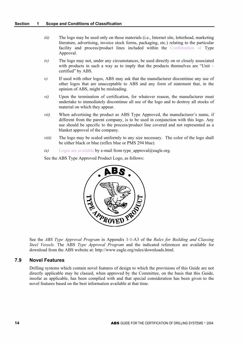
iii) The logo may be used only on those materials (i.e., Internet site, letterhead, marketing literature, advertising, invoice stock forms, packaging, etc.) relating to the particular facility and process/product lines included within the Confirmation of Type Approval.
iv) The logo may not, under any circumstances, be used directly on or closely associated with products in such a way as to imply that the products themselves are “Unit – certified” by ABS.
v) If used with other logos, ABS may ask that the manufacturer discontinue any use of other logos that are unacceptable to ABS and any form of statement that, in the opinion of ABS, might be misleading.
vi) Upon the termination of certification, for whatever reason, the manufacturer must undertake to immediately discontinue all use of the logo and to destroy all stocks of material on which they appear.
vii) When advertising the product as ABS Type Approved, the manufacturer’s name, if different from the parent company, is to be used in conjunction with this logo. Any use should be specific to the process/product line covered and not represented as a blanket approval of the company.
viii) The logo may be scaled uniformly to any size necessary. The color of the logo shall be either black or blue (reflex blue or PMS 294 blue).
ix) Logos are available by e-mail from [email protected].
See the ABS Type Approved Product Logo, as follows:
See the ABS Type Approval Program in Appendix 1-1-A3 of the Rules for Building and Classing Steel Vessels. The ABS Type Approval Program and the indicated references are available for download from the ABS website at: http://www.eagle.org/rules/downloads.html.
7.9 Novel Features Drilling systems which contain novel features of design to which the provisions of this Guide are not directly applicable may be classed, when approved by the Committee, on the basis that this Guide, insofar as applicable, has been complied with and that special consideration has been given to the novel features based on the best information available at that time.
Section 1 Scope and Conditions of Classification
ABS GUIDE FOR THE CERTIFICATION OF DRILLING SYSTEMS . 2004 15
7.11 Risk Evaluations for Alternative Arrangements and Novel Features Risk evaluations for alternative arrangements and novel features are a voluntary option for the demonstration of compliance with ABS Rules and Guides, or any recognized standard, which can be applied at the specific request of the designer or manufacturer.
When applied, risk assessment techniques should demonstrate that alternatives and novel features provide acceptable levels of safety in line with current offshore and marine industry practice. The ABS Guide for Risk Evaluations for the Classification of Marine-Related Facilities provides guidance to ABS clients on how to prepare a risk evaluation to demonstrate equivalency or acceptability for a proposed drilling system design.
Risk evaluations for the justification of alternative arrangements or novel features may be applicable either to the installation as a whole, or to individual systems, subsystems or components. The Bureau will consider the application of risk evaluations for alternative arrangements and novel features in the design of the drilling system, verification surveys during construction and surveys for maintenance of Class.
Portions of the drilling system or any of its components not explicitly included in the risk evaluation submitted to ABS are to comply with any applicable part of the ABS Rules and Guides. If any proposed alternative arrangement or novel feature affects any applicable requirements of Flag and Coastal State, it is the responsibility of the Owner to discuss with the applicable authorities the acceptance of alternatives based on risk evaluations.
7.13 Effective Date of Change of Requirement
7.13.1 Effective Date This Guide and subsequent changes to this Guide are to become effective on the date specified by the Bureau. In general, the effective date is not less than six months from the date on which the Guide is published and released for its use. However, the Bureau may bring into force the Guide or individual changes before that date, if necessary or appropriate.
7.13.2 Implementation of Rule Changes In general, until the effective date, plan approval for designs will follow prior practice, unless review under the latest Guide is specifically requested by the party signatory to the application for classification. If one or more systems are to be constructed from plans previously approved, no retroactive application of the subsequent Rule changes will be required, except as may be necessary or appropriate for all contemplated construction.
9 Other Regulations
9.1 International and Other Regulations While this Guide covers the requirements for the classification of drilling systems and their equipment, the attention of Owners, designers and builders is directed to the regulations of international, governmental and other authorities dealing with those requirements in addition to or over and above the classification requirements.
Where authorized by the Administration of a country signatory thereto and upon request of the Owners of a classed drilling system or one intended to be classed, the Bureau will survey for compliance with the provision of International and Governmental Conventions and Codes, as applicable.

Section 1 Scope and Conditions of Classification
16 ABS GUIDE FOR THE CERTIFICATION OF DRILLING SYSTEMS . 2004
9.3 Governmental Regulations Where authorized by a government agency and upon request of the Owners of a new or existing drilling system, the Bureau will survey and certify a classed drilling system or one intended to be classed for compliance with particular regulations of that government on their behalf.
11 IACS Audit The International Association of Classification Societies (IACS) conducts audits of processes followed by all of its member societies to assess the degree of compliance with the IACS Quality System Certification Scheme requirements. For this purpose, auditors for IACS may accompany ABS personnel at any stage of the classification or statutory work, which may necessitate the auditors having access to the drilling system and its equipment or access to the premises of the builder or manufacturer. In such instances, prior authorization for the auditor’s access will be sought by the local ABS office.
13 Submission of Plans Section 4, Table 1 identifies requirements for a typical list of drilling system components that will be part of the certification process for an ABS-certified drilling system. In most cases, manufacturer’s component and system related drawings, calculations and documentation would be required for submittal to substantiate the design of the system or component. In these cases, upon satisfactory completion of ABS review of the manufacturer’s submittal, ABS Engineers will issue a review letter. This letter, in conjunction with the submitted package, will be used and referenced during surveys and subsequently issued reports by attending ABS Surveyors. Upon satisfactory completion of all of the required engineering and survey processes, ABS will issue the Classification Certificate to the operating unit, including the Class notation CDS (abbreviation for Certified Drilling System).
15 Conditions for Survey After Construction
15.1 Damage, Failure and Repair
15.1.1 Examination and Repair Damage, failure, deterioration or repair to the drilling system and its equipment which affects classification is to be submitted by the Owners or their representatives for examination by the Surveyor at the first opportunity. All repairs found necessary by the Surveyor are to be carried out to the Surveyor’s satisfaction.
15.1.2 Repairs Where repairs to the drilling system and its equipment which may affect classification are planned in advance to be carried out, a complete repair procedure including the extent of the proposed repair and the need for Surveyor’s attendance is to be submitted to and agreed upon by the Surveyor reasonably in advance. Failure to notify ABS in advance of the repairs may result in suspension of the drilling system’s classification until such time as the repair is redone or evidence is submitted to satisfy the Surveyor that the repair was properly carried out. The above is not intended to include maintenance and overhaul to machinery and equipment, in accordance with recommended manufacturer’s procedures and established marine and offshore practice, which do not require ABS approval. However, any repair as a result of such maintenance and overhauls which affects or may affect classification is to be noted in the drilling system’s log and submitted to the Surveyors, as required by 1/15.1.1.
Section 1 Scope and Conditions of Classification
ABS GUIDE FOR THE CERTIFICATION OF DRILLING SYSTEMS . 2004 17
15.1.3 Representation Nothing contained in this Section or in a Rule or regulation of any government or other administration, or the issuance of any report or certificate pursuant to this Section or such a Rule or regulation, is to be deemed to enlarge upon the representations expressed in 1/1.1 through 1/1.7 hereof, and the issuance and use of any such reports or certificates are to be governed in all respects by 1/1.1 through 1/1.7 hereof.
15.1.4 Temporary Installation, Maintenance, Modification, Repair or Replacements The Bureau is to be notified of the Owner’s intention to install temporary equipment that can affect the safety or intended functioning of the certified drilling system. The installation of temporary equipment is to be no less effective than permanent drilling system equipment. The Bureau reserves the right to certify such equipment and is to be advised of temporary installations.
When the components of the drilling system are subject to annual maintenance or inspections due to repairs by qualified personnel on the drilling unit or by an authorized company/manufacturer offshore or onshore, the Bureau is to be notified for survey of the component preferably before it is placed into service. These surveys will be carried out in accordance with API requirements or other recognized codes/standards referenced in this Guide and shall be considered part of the Bureau’s Annual Survey for Drilling Systems.
Where a major modification or replacement is made to components that are part of a certified drilling system, the Bureau is to be notified and the applicable requirements of this Guide are to be met.
15.3 Notification and Availability for Survey The Surveyors are to have access to classed drilling systems and their equipment at all reasonable times. For the purpose of Surveyor monitoring, monitoring Surveyors are also to have access to classed drilling systems and their equipment at all reasonable times. Such access may include attendance at the same time as the assigned Surveyor or during a subsequent visit without the assigned Surveyor. The Owners or their representatives are to notify the Surveyors for inspection on occasions when the units on which the drilling systems are installed are in dry dock or on a slipway.
The Surveyors are to undertake all surveys on classed drilling systems and their equipment upon request, with adequate notification, of the Owners or their representatives, and are to report thereon to the Committee. Should the Surveyors find occasion during any survey to recommend repairs or further examination, notification is to be given immediately to the Owners or their representatives so that appropriate action may be taken. The Surveyors are to avail themselves of every convenient opportunity for carrying out periodical surveys in conjunction with surveys of damages and repairs in order to avoid duplication of work.
17 Units
This Guide is written in three systems of units, viz., SI units, MKS units and US customary units. Each system is to be used independently of any other system. Unless indicated otherwise, the format of presentation of the three systems of units in this Guide is as follows:
SI units (MKS units, US customary units)
19 Fees
Fees in accordance with normal ABS practice will be charged for all services rendered by ABS. Expenses incurred by ABS in connection with these services will be charged in addition to the fees. Fees and expenses will be billed to the party requesting that particular service.
Section 1 Scope and Conditions of Classification
18 ABS GUIDE FOR THE CERTIFICATION OF DRILLING SYSTEMS . 2004
21 Disagreement
21.1 Rules and Guides Any disagreement regarding either the proper interpretation of Rules and Guides or the translation of Rules and Guides from the English language edition is to be referred to the Bureau for resolution.
21.3 Surveyor In case of disagreement between the Owners or builders and the Surveyors regarding the material, workmanship, extent of repairs or application of the Rules and Guides relating to any system classed or proposed to be classed by ABS, an appeal may be made in writing to the Committee, who will order a special survey to be held. Should the opinion of the Surveyor be confirmed, expense of this special survey is to be paid by the party appealing.
23 Limitation of Liability
The combined liability of the American Bureau of Shipping, its committees, officers, employees, agents or subcontractors for any loss, claim or damage arising from its negligent performance or nonperformance of any of its services or from breach of any implied or express warranty of workmanlike performance in connection with those services, or from any other reason, to any person, corporation, partnership, business entity, sovereign, country or nation, will be limited to the greater of a) $100,000 or b) an amount equal to ten times the sum actually paid for the services alleged to be deficient.
The limitation of liability may be increased, up to an amount twenty-five times the sum paid for services, upon receipt of Client’s written request at or before the time of performance of services, and upon payment by Client of an additional fee of $10.00 for every $1,000.00 increase in the limitation.
25 References
Some of the applicable requirements of the following Rules, Guides, Codes or Standards are referenced in this Guide are listed below:
• ABS MODU Rules – ABS Rules for Building and Classing Mobile Offshore Drilling Units
• ABS Steel Vessel Rules – ABS Rules for Building and Classing Steel Vessels
• ABS NDI Guide – ABS Guide for Nondestructive Inspection of Hull Welds
• ABS OI Rules – ABS Rules for Building and Classing Offshore Installations
• ABS Facilities Guide – ABS Guide for Building and Classing Facilities on Offshore Installations
• ABS RBI Guide – ABS Guide for Surveys using Risk-Based Inspections for the Offshore Industry
• ABS RCM Guide – ABS Guide for Surveys based on Reliability-Centered Maintenance
• AGMA – American Gear Manufacturers Association
• AISC – American Institute of Steel Construction
• ANSI – American National Standards Institute
• API – American Petroleum Institute
• ASME – American Society of Mechanical Engineers
Section 1 Scope and Conditions of Classification
ABS GUIDE FOR THE CERTIFICATION OF DRILLING SYSTEMS . 2004 19
• ASNT – American Society for Nondestructive Testing
• ASTM – American Society for Testing and Materials
• IEEE – Institute of Electrical and Electronic Engineers
• NACE – National Association of Corrosion Engineers
• NEMA – National Electrical Manufacturers Association
• NFPA – National Fire Protection Association
• UL – Underwriters Laboratory
ABS is prepared to consider other appropriate alternative methods and recognized codes of practice.

This Page Intentionally Left Blank
ABS GUIDE FOR THE CERTIFICATION OF DRILLING SYSTEMS . 2004 21
S E C T I O N 2 Design of Drilling Systems
1 Drilling System Basics
1.1 General The designer of the drilling system is to evaluate the system as a whole, considering the interfacing and interdependence of subsystems. Except as indicated below, the required drawings and data to be submitted for design review related to the drilling systems are listed in Subsection 2/7.
1.3 Equipment Layout Drilling system components are to be arranged so that electrical cables and cableways, exhaust ducting and air intake ducting, control and shutdown systems and safety systems are protected from damage during drilling operations. Equipment arrangements are to provide access for inspection and servicing and a safe means of egress from machinery spaces. The installation of electrical equipment within hazardous areas is to be in compliance with the ABS MODU Rules. Combustion equipment and combustion engines should not be located in hazardous areas.
1.5 Overpressurization Protection The equipment will be reviewed for the specified design parameters. It is to be the responsibility of the designer to specify and design equipment and systems to the most severe combination of natural (reservoir), flow restriction and thermally induced pressures. Systems that may be exposed to pressure excursions greater than that for which they are designed are to be safeguarded by suitable pressure relief valves or the equivalent.
1.7 Materials The materials for each component are to be selected in consideration of their fitness for the intended service and designated scope of work. The experience of the manufacturer and designer and pertinent performance records will be considered in addition to the general requirements of Section 6 of this Guide.
1.9 Welding and Nondestructive Examination All welds, material and welding procedures are to be selected in consideration of their fitness for the intended service and designed scope of work. General requirements for welding and nondestructive examination are covered in Section 7 of this Guide.
Section 2 Design of Drilling Systems
22 ABS GUIDE FOR THE CERTIFICATION OF DRILLING SYSTEMS . 2004
3 Design Specifications
Design specifications are to be submitted for approval for each major component. Specific component drawings and data to be submitted are outlined in Subsection 2/7 of this Guide.
The design specification is to consider the most adverse combination of applicable loads listed in 2/5.9 of this Guide and is to consist of sufficient drawings, data and calculations to substantiate the design.
Material, welding and nondestructive examination, and testing procedures/specifications utilized in the production of each component are to be included in the fabrication specification and are to comply with the applicable section of this Guide.
5 Design Considerations
5.1 Recognized Standards The submitted design is to be in accordance with the requirements of this Guide and the specified standards as referenced herein. Designs complying with other international or national standards not listed in Appendix 1 will be subject to special consideration.
Manufacturers are required to provide ABS an affidavit of compliance with an applicable recognized standard. This affidavit is to accompany all drilling system components that are placed onboard the drilling unit, and shall be verified by the Surveyor prior to final certification of the drilling system. It is expected that an affidavit of compliance to be issued by the manufacturer be similar to the sample shown in Appendix 2 of this Guide.
5.3 Alternative Basis of Design Designs based on manufacturer’s standards may also be accepted. In such cases, complete details of manufacturer’s standard and engineering justification are to be submitted for review. The manufacturer will be required to demonstrate by way of testing or analysis that the design criteria employed results in a level of safety consistent with that of a recognized standard or code of practice. Where strain gauge testing, fracture analysis, proof testing or similar procedures form a part of the manufacturer’s design criteria, the procedure is to be submitted for review.
5.7 Corrosion/Erosion Allowance Where components are subjected to a corrosive or erosive environment, the design of components is to include allowances for such extra material as specified by a recognized standard. Alternative allowances will be considered when supplemented with technical justification. This justification can be in the form of previous documented experience or consideration of in-service thickness monitoring records, in which case, a detailed summary of the monitoring records is to be submitted for consideration. The amount of additional material needed will be determined based on the predicted rate of corrosion and/or erosion and the design service life of the component. In the absence of any standard allowance or submitted information, a corrosion allowance of 0.125 mm (50 mils.) will be utilized.
Section 2 Design of Drilling Systems
ABS GUIDE FOR THE CERTIFICATION OF DRILLING SYSTEMS . 2004 23
5.9 Operating Conditions The components are to be designed to account for all applicable environmental operation loads. These include, but are not limited to, the following:
i) Environmental Conditions
• earthquake
• ice
• current, waves
• wind
• temperature
ii) Operational
• static pressure
• transient pressure excursion
• temperature excursion
• tension
• bending
• vibration
• acceleration loads due to movement of the drilling unit
iii) Test Loads
7 Design Plans and Data
Plans and data to be submitted for design review shall be submitted at least in triplicate; one copy for return to the submitter, one copy retained by ABS engineering office, and one copy for the use of the attending Surveyor. Full size prints of documents are preferred. If this is not feasible, all reduced prints must be clearly legible in all details.
7.1 Systems The detailed, dimensioned drawings listed below are to be submitted and are to include material specifications, welding specifications and dimensions, and strength calculations:
i) Process schematics and narrative description of system design parameters of pressure, temperature and flows of drilling and stimulation. Steady state conditions of design and potential transient excursions that impact the design should be clearly articulated.
ii) General arrangement, equipment layout and elevation drawings showing the location of all machinery and stores, electrical equipment components and piping systems.
iii) Piping arrangements and general details, including pipe and fitting materials, specifications, sizes and pressure ratings. Piping system stress calculations, operational sizing, design analysis and weld details are to be submitted.
iv) Pressure vessel design drawings, including dimensional plans, design calculations, material specifications, fabrication procedures and weld details for all pressure vessels, supports and internal components.
v) Complete details of burners, including pilots, igniters, water seals, etc.
Section 2 Design of Drilling Systems
24 ABS GUIDE FOR THE CERTIFICATION OF DRILLING SYSTEMS . 2004
vi) Hydrocarbon and hydrogen sulphide gas detection system plans and data, including detectors, piping, set points, type of detectors, and location of alarm panels, and recalibration program for gas detectors.
vii) Plans showing sizing arrangements, materials, backpressure and capacity calculations for all pressure relief systems.
viii) Riser details and analysis including arrangements, dimensions, materials and welding details. Design criteria for flexible hoses, as applicable.
ix) Control system details and operations panel arrangements for surface and subsurface blow-out preventer (BOP) systems
x) Blow-out preventer stack configuration and individual ram details.
xi) Blow-out preventer design criteria and supporting analysis, including calculations and any documented empirical data used therein.
xii) Mud, cement and other high-pressure application pumping unit documentation showing compliance with a recognized standard is to be submitted. Additionally, detailed dimensioned drawings of pressure retaining and gear units (if any) are to be submitted along with material, welding specifications, design criteria and supporting analysis.
xiii) Rotary drilling equipment detailed drawings for drawworks and brake, crown block, traveling block, hook and swivel, power swivel, pipe rackers/manipulator systems, including all other primary lifting components. Additionally, details of stabbing boards, racking platforms, man-riding elevators/winches and other lifting devices are to have detailed drawings submitted as per Section 4, Table 1.
7.3 Piping Design Documentation The piping design documentation to be submitted for review shall include the following information:
i) Mechanical Flowsheets (piping and instrument diagrams) complete with reference to appropriate piping class and valves in the piping design specification.
ii) Piping Design Specification covering all piping classes and valving and other piping-related parts with the following information per piping standard rating.
iii) Design pressure and pressure rating.
iv) Design temperature (maximum and minimum).
v) Fluid medium (specifically note if piping standard rating is for sour service).
vi) Design code and dimensional standards including corrosion/erosion allowances.
vii) Wall thickness for each line size.
viii) Rating and type of flanges, valves, fittings, gaskets, etc.
ix) Material specifications for pipes, hoses, fittings, flanges, bolts, nuts, valve bodies, bonnets, stems, seats, springs, actuators.
x) List of special components.
xi) Stress Calculations and Drawings or Test Reports for non-standard piping elements.
xii) Piping Fabrication Specification which will include:
• identification and marking method
• piping pressure testing procedure
• nondestructive testing methods
Section 2 Design of Drilling Systems
ABS GUIDE FOR THE CERTIFICATION OF DRILLING SYSTEMS . 2004 25
• pipe welding, bending and heat treating procedures
• piping installation procedures, including support systems
• damage repair procedures
7.5 Derrick Documentation The following derrick plans and data are to be submitted for design review:
i) Plans showing size and general dimensions of the drilling derrick. All loads to be considered are to be stated.
ii) Structural drawings of main structural elements of drilling derrick.
iii) Material specifications of profiles, plates and bolts (if bolted design).
iv) Welding procedure specifications.
v) Fabrication specifications.
vi) Name and address of derrick manufacturer.
vii) Vendors.
viii) Model No.
ix) General arrangement of the derrick.
x) Intended location of the derrick or the installation.
xi) Ratings of the derrick.
xii) Limitations of use and design ambient temperature and operational conditions of the derrick.
xiii) Codes and standards, etc., applied for the derrick structure, system and details.
xiv) Pertinent stress and loading calculations.
7.7 Burner/Flare Booms The following boom plans and data are to be submitted for design review:
i) Plans showing sizes and general dimensions of the boom and supporting structural elements.
ii) Drawings of main structural elements of boom and other load-sharing components of the boom.
iii) Material specifications of profiles, plates and bolts.
iv) Welding procedure of boom manufacturer.
v) Vendors.
vi) Model No.
vii) General arrangement of the boom.
viii) Intended location of the boom on the installation.
ix) Limitations of use and design ambient temperature and operational conditions of the boom.
x) Codes and Standards etc., applied for the boom structure, system and details.
xi) Pertinent calculations, including statement of maximum loads.
Section 2 Design of Drilling Systems
26 ABS GUIDE FOR THE CERTIFICATION OF DRILLING SYSTEMS . 2004
7.9 Electrical Systems The following electrical plans and data are to be submitted for design review:
i) Rectifier systems, generators, motors and motor controllers used solely for drilling functions, including complete rating, insulation class, rated ambient temperature, temperature rise, enclosure type, details of construction, details of cooling system, electrical characteristics and standard to which manufactured.
ii) Batteries used for emergency blow-out preventer control service, including installation, arrangement and details of batteries, where provided, to include charging apparatus, ventilation and corrosion protection.
iii) Schematics and arrangement drawings of switchboards.
7.11 Instrumentation and Control Systems The following instrumentation and control system plans and data are to be submitted for design review:
i) Arrangement plans showing location of units controlled, instrumentation and control devices. ii) Specifications for control and instrumentation equipment. iii) Set points for control system components. iv) Control system operating and maintenance manuals. v) Hazards analysis for control systems. vi) Calculations for control systems demonstrating the system’s ability to react adequately to
anticipated occurrences, including transients. vii) Arrangements and details of control consoles, including front views, installation arrangements
together with schematic plans and logic description for all power, control and monitoring systems, including their functions.
viii) Kind and size of all electrical cables and wiring associated with the control systems, including voltage rating, service voltage and currents, together with overload and short-circuit protection.
ix) Schematic plans and logic description of hydraulic and pneumatic control systems together with all interconnections, piping sizes and materials, including working pressures and relief-valve settings.
x) Description of all alarm and emergency tripping arrangements and functional sketches or description of all special valves, actuators, sensors and relays.
7.13 Equipment Documentation Unless required otherwise in previous Subsections 2/7.1 through 2/7.11 of this Guide, particularly in Section 4, Table 1, a specification for manufacture, including the following information for all drilling systems and components, are to be made available to the Bureau: i) Design specifications ii) Drawings with sufficient details and dimensions to evaluate the design iii) Strength calculations iv) Bill of Materials complete with material specifications v) Fabrication specifications, including welding heat treatment, type and extent of NDT testing vi) Stress analysis, as appropriate vii) Type testing certification issued by a recognized independent testing agency, as appropriate
Section 2 Design of Drilling Systems
ABS GUIDE FOR THE CERTIFICATION OF DRILLING SYSTEMS . 2004 27
9 Risk Assessment Risk assessment techniques may be used to demonstrate that alternatives and novel features provide acceptable levels of safety in line with current offshore and marine industry practice. The ABS Guide for Risk Evaluations for the Classification of Marine-Related Facilities provides guidance to ABS clients on how to prepare a risk evaluation to demonstrate equivalency or acceptability for a proposed drilling system design. Risk evaluations for the justification of alternative arrangements or novel features may be applicable to individual systems, subsystems or components. The Bureau will consider the application of risk evaluations for alternative arrangements and novel features in the design of the drilling system, verification surveys during construction and surveys for maintenance of class. Portions of the drilling system or any of its components not explicitly included in the risk evaluation submitted to ABS are to comply with any applicable part of the ABS Rules and this Guide. If any proposed alternative arrangement or novel feature affects any applicable requirements of Flag and Coastal State, it is the responsibility of the Owner to discuss with the applicable authorities the acceptance of alternatives based on risk evaluations. The risk assessment technique is a voluntary option for the demonstration of compliance of drilling equipment with this Guide. When this option is applied at the specific request of the designer or manufacturer, all hazards that may affect the drilling systems or any of its components are to be identified. A systematic process is to be applied to identify situations where a combination or sequence of events could lead to undesirable consequences (property damage, personnel safety and environmental damage), with consideration given to all foreseeable causes. The objective of the hazard identification is to identify areas of the design that may require the implementation of further risk control options in order to reduce the risk to an acceptable level. The hazard identification shall consider, as a minimum, the following events: i) Blow-out ii) Release of H2S and Combustible Gas iii) Fire iv) Explosion v) Loss of Purge Air vi) Structural Failure vii) Mechanical Failure viii) Electrical Failure ix) Loss/Failure of Mooring/Station Keeping x) Impact to Equipment xi) Dropped Objects xii) Collision xiii) Helicopter Crash The identified risk control options (prevention and mitigation measures) deemed necessary to be implemented should be considered part of the design basis of the drilling system. Appendix 4 in the ABS Guide for Risk Evaluations for the Classification of Marine-Related Facilities contains a description of the most common hazard identification techniques. Also, Appendix 2 in the same Guide provides an overview of how to assemble an appropriate risk assessment team. When the risk assessment technique is considered, ABS’ participation in the hazard identification meeting(s) is recommended. Tangible benefits can be derived by the participation of an ABS representative who will later be directly involved in reviewing the design for classification.

This Page Intentionally Left Blank

ABS GUIDE FOR THE CERTIFICATION OF DRILLING SYSTEMS . 2004 29
S E C T I O N 3 Drilling Systems
1 General
The term classification, in this document, indicates that a drilling system and its equipment have been designed, constructed, installed and surveyed in compliance with relevant ABS Rules, Guides, this Guide or other acceptable standards. The continuance of classification is dependent on the fulfillment of requirements for surveys after construction.
The degree of certification process requirements for typical drilling system components is outlined in Section 4, Table 1 of this Guide
3 Bulk Storage, Circulation and Transfer Systems
The bulk storage, circulation and transfer system equipment can be categorized as follows:
• Bulk storage and transfer equipment
• Cementing equipment
• Mud return equipment
• High pressure well circulation equipment
3.1 Bulk Storage and Transfer Equipment Typical components of the bulk storage and transfer equipment subject to certification would include bulk storage vessels, utility air system, and transport and transfer piping.
Provisions are to be made so that utility air used to transport cement or bulk mud is dried to a water dew point of at least 7°C (13°F) below the minimum ambient air temperature. All utility air piping is to be designed to be purged with dry air prior to transfer operations. The utility air transfer piping is to be fitted with relief valves set at a pressure not greater than the working pressure of the bulk storage tanks.
Bulk storage vessels are to be fitted with safety relief valves or rupture disks piped to a safe relief area. Unless they are fitted with a relief line to an open area, the use of rupture disks shall be limited to tanks installed in open areas.
A P&ID or equivalent schematic of the bulk transfer system should be clearly posted at the operator station to allow operation of the system during emergency cementing operations. If the schematic is electronic, it should be provided with an emergency source of power.
3.3 Cementing Equipment Typical components of the cementing equipment subject to certification would include cement pump, centrifugal pumps for mixing cement, piping to and from cement pumps, pulsation dampeners and safety valves.
Section 3 Drilling Systems
30 ABS GUIDE FOR THE CERTIFICATION OF DRILLING SYSTEMS . 2004
The cement pumps shall be arranged to be capable of emergency mixing and circulation, using the drilling fluid transferred from the mud pits. Cement pump installations or modifications to existing installations shall be subject to Bureau review.
The interconnect lines between systems which are used only in an emergency are to be fitted with blind or spectacle flanges, lockable valves or similar devices that can be opened at need, but which positively isolate the systems during normal operations. These flanges should be clearly identified and labeled on the P&ID, and corresponding flanges or valves are to be appropriately identified and their function indicated.
3.5 Mud Return Equipment Typical components of the mud return equipment subject to certification would include agitators, chemical mixers, degassers, desanders, desilters, centrifuges, mud pits, dump tanks, piping from degassers to burners or vents, piping of mud return, shale shakers and trip tanks.
The mud circulating piping system is to be arranged so that the mud reconditioning system may be run in a series of degasser, desander, desilter and centrifuge so as to prevent mud from entering other piping systems.
3.7 Well Circulation Equipment Typical components of the well circulation equipment subject to certification would include circulation head, control consoles/panels, Kelly, Kelly cocks, mixing pumps, mud-gas separators, mud pumps, non-return valve in drill string (inside BOP), piping for circulation of drilling fluid, pulsation dampeners, rotary hose (Kelly hose or mud hose), safety valves and standpipe manifold, or similar related equipment used for circulation.
High-pressure mud pumps are to be fitted with safety relief valves whose maximum setting is no higher than the maximum allowable pressure of the system. Relief lines from the mud system are to be self-draining. Where rupture disk type pressure relief devices are installed, rupture disks should be certified to meet a recognized standard and the disk assembly shall be subject to survey in accordance with the manufacturer’s specifications.
3.7.1 Kelly Cocks The drilling unit will be equipped with two Kelly cocks, one of which is to be mounted below the swivel, and the other at the bottom of the power swivel or Kelly. The lower Kelly cock is to be sized so that it can be run through the blow-out preventer stack when the blow-out preventers are not installed on the seabed.
Testing of Kelly cocks are to be performed bi-directionally and at a low and high pressure, with the low pressure tests first.
3.7.2 Mud, Cement and Kill Pumps The mud and cement pumps mentioned in 3/3.3 and 3/3.7 of this Guide are to also satisfy the following requirements:
i) Materials used for major pressure retaining components of the fluid end are to comply with Section 6 of this Guide.
ii) Gears are to comply with API Spec. 7.
iii) The fluid end and associated manifolds (suction and discharge) are to be hydrostatically tested to 1.5 times working pressure.
iv) Motor couplings and shafting are to comply with a recognized standard and be suitable for intended service in terms of maximum power and minimum operating temperature.
Section 3 Drilling Systems
ABS GUIDE FOR THE CERTIFICATION OF DRILLING SYSTEMS . 2004 31
v) Materials used for discharge manifold components on pumps designated as kill pumps must also comply with 6/5.1 of this Guide, regardless of minimum design temperature.
vi) The pumps are to be equipped with suitable vibration (pulsation) dampening devices.
vii) Discharge piping to comply with ASME B31-3.
viii) Belt driven mud pumps must be checked as to run-out and correct tension by OEM recommended standards.
5 Heave Compensation System
The heave compensation system equipment can be categorized as follows:
• Drill string compensation equipment
• Tensioning equipment
• Active heave drawworks compensation
Theory of operation, included in submitted plans, should include the backup braking system and computer/control redundancy studies.
5.1 Drill String Compensation Equipment Typical components of the drill string compensation equipment subject to certification would include accumulators, air compressors, air dryers, compensators, control consoles/panels, hydraulic cylinders, piping, pressure vessels, sheaves and wire ropes.
5.3 Tensioning Equipment Typical components of the tensioning equipment subject to certification would include accumulators, air compressors, air dryers, control consoles/panels, hydraulic cylinders, piping, pressure vessels, tensioners (riser, guideline and podline), sheaves for tensioners, telescopic arms and wire ropes.
5.5 Motion Compensation and Tensioning System Component Specific Requirements Piping and hoses are to be in accordance with Section 5 of this Guide.
Load-carrying parts are to be in accordance with 3/7.3.6i), 3/7.3.6iii) and 3/7.3.6iv) of this Guide. If the locking mechanism is in the load path, it should be in accordance with 3/7.3.6i), 3/7.3.6iii) and 3/7.3.6iv) of this Guide.
Hydraulic and pneumatic cylinders are to be in accordance with 3/17.3.
7 Hoisting, Rotating and Pipe Handling System
The hoisting, rotating and pipe handling system equipment can be categorized as follows:
• Derricks
• Hoisting equipment
• Miscellaneous equipment
• Pipe handling equipment
• Rotary equipment
Section 3 Drilling Systems
32 ABS GUIDE FOR THE CERTIFICATION OF DRILLING SYSTEMS . 2004
7.1 Derricks/Masts
7.1.1 Recognized Codes and Standards Except as provided below, the design and fabrication of drilling derricks/masts are to be in accordance with API Spec. 4E and API Spec. 4F. Alternatively, other recognized standards may be used when agreed to by ABS.
7.1.2 Design Loads Where API Spec. 4F is used as the basis of the structural design, the definition of forces and loads, and the applicable loading conditions are to be as specified therein. The Owner is required to specify appropriate values to establish the static and dynamic loadings on the derrick/mast, as required in API Spec. 4F. However, the following loads are also to be given consideration, where applicable:
i) The accumulation of ice and snow on a structure in increasing its dead load and wind-induced load.
ii) The use of wind speeds higher than those provided in Spec. 4F, where required by the operational demands of the user. The wind speed to be considered in the Survival Case (no hook load or setback loads) is not to be taken less than 51.4 m/sec. (100 knots).
iii) The use of a higher specified fraction of the rated setback, where required by the operational demands of the user.
iv) For the calculation of dynamic loading induced by floating hull motion, the vertical distance and the horizontal distance, where applicable, between the center of flotation of the host drilling unit and the center of gravity of the derrick are to be provided by the Owner/Operator to the derrick designer and are to be used in the calculations. Note that the horizontal distance is to be considered in addition to the vertical distance in the transit condition for self-elevating drilling units.
As applicable, the design live load on walkways is to comply with 3/7.1.3 of this Guide. Only the dead loads resulting from the presence of walkways, ladders and guardrails need be considered in the design of the derrick. The local design of ladders, guardrails and walkways and their connections to the derrick or substructure is to consider anticipated live loads.
7.1.3 Live Loads for Local Structure and Arrangements The arrangement of members should allow the free drainage of water from the structure. The following are the minimum vertical live loads that are to be considered in the design of walkways:
• General Traffic Areas – 4,500 N/m2 (94 psf)
• Working Platforms – 9,000 N/m2 (188 psf)
• Storage Areas –13,000 N/m2 (272 psf)
Attention is drawn to the fact that various national and international regulatory bodies have requirements for the loading, arrangement and construction of local structure such as guardrails, ladders and walkways. ABS will include in the scope of its design review and fabrication inspection such requirements, when requested.
7.1.4 Allowable Stresses To preclude excessive stresses in members and connections, or buckling, reference is to be made to the allowable stress limits given in the AISC Manual of Steel Construction or other equivalent and recognized code.
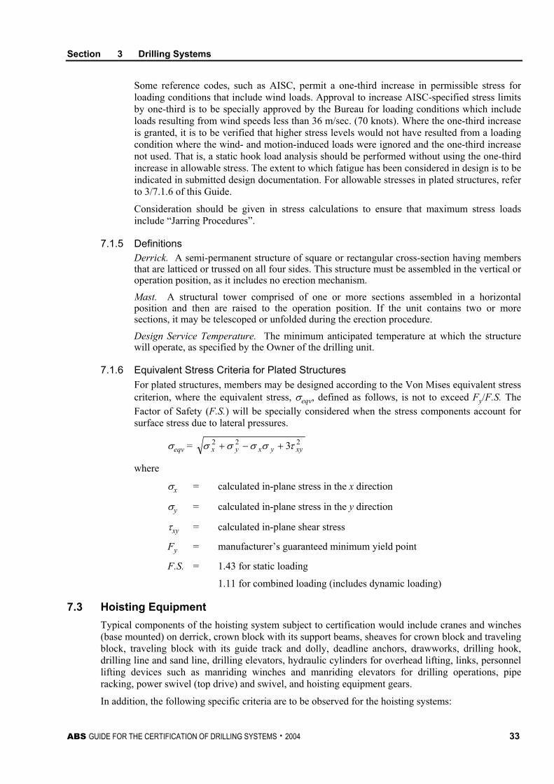
Section 3 Drilling Systems
ABS GUIDE FOR THE CERTIFICATION OF DRILLING SYSTEMS . 2004 33
Some reference codes, such as AISC, permit a one-third increase in permissible stress for loading conditions that include wind loads. Approval to increase AISC-specified stress limits by one-third is to be specially approved by the Bureau for loading conditions which include loads resulting from wind speeds less than 36 m/sec. (70 knots). Where the one-third increase is granted, it is to be verified that higher stress levels would not have resulted from a loading condition where the wind- and motion-induced loads were ignored and the one-third increase not used. That is, a static hook load analysis should be performed without using the one-third increase in allowable stress. The extent to which fatigue has been considered in design is to be indicated in submitted design documentation. For allowable stresses in plated structures, refer to 3/7.1.6 of this Guide.
Consideration should be given in stress calculations to ensure that maximum stress loads include “Jarring Procedures”.
7.1.5 Definitions Derrick. A semi-permanent structure of square or rectangular cross-section having members that are latticed or trussed on all four sides. This structure must be assembled in the vertical or operation position, as it includes no erection mechanism. Mast. A structural tower comprised of one or more sections assembled in a horizontal position and then are raised to the operation position. If the unit contains two or more sections, it may be telescoped or unfolded during the erection procedure. Design Service Temperature. The minimum anticipated temperature at which the structure will operate, as specified by the Owner of the drilling unit.
7.1.6 Equivalent Stress Criteria for Plated Structures For plated structures, members may be designed according to the Von Mises equivalent stress criterion, where the equivalent stress, σeqv, defined as follows, is not to exceed Fy/F.S. The Factor of Safety (F.S.) will be specially considered when the stress components account for surface stress due to lateral pressures.
σeqv = 222 3 xyyxyx τσσσσ +−+
where
σx = calculated in-plane stress in the x direction
σy = calculated in-plane stress in the y direction
τxy = calculated in-plane shear stress
Fy = manufacturer’s guaranteed minimum yield point
F.S. = 1.43 for static loading
1.11 for combined loading (includes dynamic loading)
7.3 Hoisting Equipment Typical components of the hoisting system subject to certification would include cranes and winches (base mounted) on derrick, crown block with its support beams, sheaves for crown block and traveling block, traveling block with its guide track and dolly, deadline anchors, drawworks, drilling hook, drilling line and sand line, drilling elevators, hydraulic cylinders for overhead lifting, links, personnel lifting devices such as manriding winches and manriding elevators for drilling operations, pipe racking, power swivel (top drive) and swivel, and hoisting equipment gears.
In addition, the following specific criteria are to be observed for the hoisting systems:
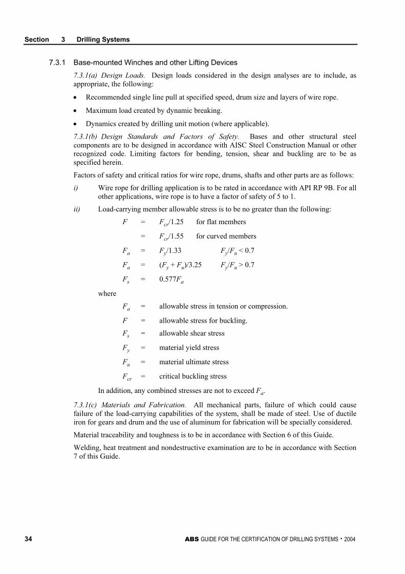
Section 3 Drilling Systems
34 ABS GUIDE FOR THE CERTIFICATION OF DRILLING SYSTEMS . 2004
7.3.1 Base-mounted Winches and other Lifting Devices
7.3.1(a) Design Loads. Design loads considered in the design analyses are to include, as appropriate, the following:
• Recommended single line pull at specified speed, drum size and layers of wire rope.
• Maximum load created by dynamic breaking.
• Dynamics created by drilling unit motion (where applicable).
7.3.1(b) Design Standards and Factors of Safety. Bases and other structural steel components are to be designed in accordance with AISC Steel Construction Manual or other recognized code. Limiting factors for bending, tension, shear and buckling are to be as specified herein.
Factors of safety and critical ratios for wire rope, drums, shafts and other parts are as follows:
i) Wire rope for drilling application is to be rated in accordance with API RP 9B. For all other applications, wire rope is to have a factor of safety of 5 to 1.
ii) Load-carrying member allowable stress is to be no greater than the following:
F = Fcr/1.25 for flat members
= Fcr/1.55 for curved members
Fa = Fy/1.33 Fy/Fu < 0.7
Fa = (Fy + Fu)/3.25 Fy/Fu > 0.7
Fs = 0.577Fa
where
Fa = allowable stress in tension or compression.
F = allowable stress for buckling.
Fs = allowable shear stress
Fy = material yield stress
Fu = material ultimate stress
Fcr = critical buckling stress
In addition, any combined stresses are not to exceed Fa.
7.3.1(c) Materials and Fabrication. All mechanical parts, failure of which could cause failure of the load-carrying capabilities of the system, shall be made of steel. Use of ductile iron for gears and drum and the use of aluminum for fabrication will be specially considered.
Material traceability and toughness is to be in accordance with Section 6 of this Guide.
Welding, heat treatment and nondestructive examination are to be in accordance with Section 7 of this Guide.
Section 3 Drilling Systems
ABS GUIDE FOR THE CERTIFICATION OF DRILLING SYSTEMS . 2004 35
7.3.1(d) Drums. The drum capacity is to accommodate the recommended rope size and length necessary to perform the function required for the load-handling equipment with which the hoist is used.
• Plain or grooved drums will normally be considered acceptable, provided no less than five full wraps of rope remain on the drum with the load in its lowest possible position. Other design specifications/standards will be subject to special consideration based on calculations submitted to this Bureau.
• Each drum end of the rope shall be anchored by a clamp attached to the drum, or by a socket arrangement approved by the hoist or rope manufacturer, providing for attachment of rope to the drum.
• The outermost wrap of a wire rope in any load case is to be less than two (2) rope diameters from the outer radius of the drum flange.
Diameter of the drum shall provide first layer rope pitch diameter of not less than 18 times the nominal diameter of the rope used.
7.3.1(e) Wire Ropes. Wire ropes are to be constructed in accordance with a recognized standard applicable to the intended service, such as API specification 9A. Usage records such as ton-mile records are to be maintained and wire rope changed out in accordance with manufacturer’s recommendations.
Regardless of ton-miles, wire ropes used in manriding applications should be replaced if kinks, rust, flattening, strand breakage or other physical damage is visible. Wire ropes used in non-manriding applications should be replaced if damage exceeds manufacturer’s specifications for their rated capacity or if damage could affect smooth passage through sheaves.
7.3.1(f) Brakes. A power control braking means such as regenerative, dynamic, counter torque breaking, controlled lowering or a mechanically controlled braking means shall be provided and shall be capable of maintaining controlled lowering speeds.
Brakes are to have the ability to stop and hold 100% of the design load with the outermost layer of wire on the drum. Brakes are to set automatically on loss of power and when the winch lever is returned to neutral.
Thermal capacity of the brakes as outlined in the manufacturer’s ratings or charts is to be suitable for the intended services.
Brake linings containing asbestos material are not to be used.
Documentation and calculations for the braking effect of the newer AC motors should be submitted when they are the only backup system to the disc brakes.
7.3.1(g) Testing
i) Load Test – After installation, the system is to be tested with a load equal to 125% of the rated capacity in the presence of the Surveyor. Satisfactory operation of power drives and brakes is to be demonstrated. After being tested, the system with all its components is to be visually examined for permanent deformation and failure.
ii) Performance Test – Testing in the presence of the Surveyor is to demonstrate that rated line pull can be achieved at rated speed with the outermost layer of wire on the drum.
iii) Braking Test – It is to be demonstrated that the brakes have the ability to stop and hold 100% of the design load. Confirmatory testing to demonstrate the braking effect of the newer AC motors, mentioned above in 3/7.3.1(f), should also be carried out upon installation onboard.
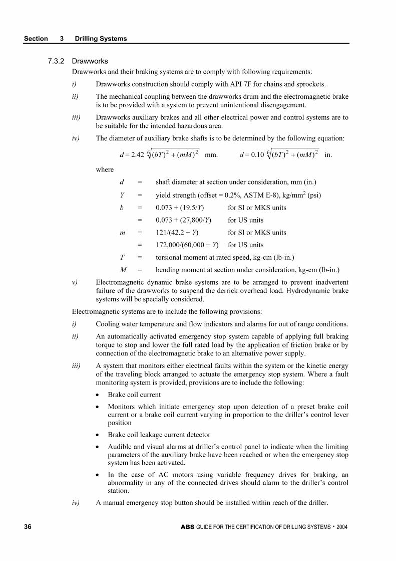
Section 3 Drilling Systems
36 ABS GUIDE FOR THE CERTIFICATION OF DRILLING SYSTEMS . 2004
7.3.2 Drawworks Drawworks and their braking systems are to comply with following requirements:
i) Drawworks construction should comply with API 7F for chains and sprockets.
ii) The mechanical coupling between the drawworks drum and the electromagnetic brake is to be provided with a system to prevent unintentional disengagement.
iii) Drawworks auxiliary brakes and all other electrical power and control systems are to be suitable for the intended hazardous area.
iv) The diameter of auxiliary brake shafts is to be determined by the following equation:
d = 2.42 6 22 )()( mMbT + mm. d = 0.10 6 22 )()( mMbT + in.
where
d = shaft diameter at section under consideration, mm (in.)
Y = yield strength (offset = 0.2%, ASTM E-8), kg/mm2 (psi)
b = 0.073 + (19.5/Y) for SI or MKS units
= 0.073 + (27,800/Y) for US units
m = 121/(42.2 + Y) for SI or MKS units
= 172,000/(60,000 + Y) for US units
T = torsional moment at rated speed, kg-cm (lb-in.)
M = bending moment at section under consideration, kg-cm (lb-in.)
v) Electromagnetic dynamic brake systems are to be arranged to prevent inadvertent failure of the drawworks to suspend the derrick overhead load. Hydrodynamic brake systems will be specially considered.
Electromagnetic systems are to include the following provisions:
i) Cooling water temperature and flow indicators and alarms for out of range conditions.
ii) An automatically activated emergency stop system capable of applying full braking torque to stop and lower the full rated load by the application of friction brake or by connection of the electromagnetic brake to an alternative power supply.
iii) A system that monitors either electrical faults within the system or the kinetic energy of the traveling block arranged to actuate the emergency stop system. Where a fault monitoring system is provided, provisions are to include the following:
• Brake coil current • Monitors which initiate emergency stop upon detection of a preset brake coil
current or a brake coil current varying in proportion to the driller’s control lever position
• Brake coil leakage current detector • Audible and visual alarms at driller’s control panel to indicate when the limiting
parameters of the auxiliary brake have been reached or when the emergency stop system has been activated.
• In the case of AC motors using variable frequency drives for braking, an abnormality in any of the connected drives should alarm to the driller’s control station.
iv) A manual emergency stop button should be installed within reach of the driller.
Section 3 Drilling Systems
ABS GUIDE FOR THE CERTIFICATION OF DRILLING SYSTEMS . 2004 37
7.3.3 Personnel Lifting Devices Manriding winches are to comply with the general requirements of this Section. In addition, the following minimum criteria are to be complied with: i) The personnel rated load is to be no greater than 20% of the load calculated in
accordance with 3/7.3.2. ii) The winch operating lever should automatically return to neutral upon release from
any position. All positions should be clearly marked as to their intended function. iii) A secondary brake is to be provided to prevent the load from falling in the event of
failure of the primary automatic brake. iv) A clutch capable of disengaging shall not be fitted. v) Devices should be fitted to prevent the winch from overriding or underriding, and a
secondary means of lowering personnel should be provided in case of winch or power failure.
vi) Wire rope specifications are to be clearly defined and specific to the applicable personnel lifting device.
vii) Setting of upper limit should provide at least a vertical clearance of six (6) feet from the upper block, and the lower limit shall be set so that the winch cannot be operated with number of wraps less than specified in 3/7.3.2iv) of this Guide.
All winches shall be identified as “Manrider Only” and marked with their SWL. Personnel elevators used for access from/to the drilling system shall comply with ABS Guide for Construction of Shipboard Elevators, as far as applicable and practicable.
7.3.4 Power Swivels This equipment includes all devices used to rotate the drill string other than by means of the rotary table. This equipment shall meet the specific requirements listed below: i) Major load-carrying components are to comply with the requirements of 3/7.3.6i) of
this Guide. ii) Pressure-retaining components are to comply with the applicable requirements of
Subsection 3/17 of this Guide. iii) Electrical equipment and installations are to comply with the applicable requirements
of Subsection 3/19 of this Guide. iv) Piping systems are to comply with Section 5 of this Guide. v) Rotary hoses are to comply with API Specification 7K. vi) Gears and couplings are to comply with a recognized standard and be suitable for
their intended service in terms of maximum power rating and minimum operating temperature.
7.3.5 Safety Devices and Instrumentation Typical safety devices and instrumentation required for hoisting equipment are as follows: i) The overhead drilling hoisting equipment is to have a weight indicator installed and
the display is to be easily read from the driller’s console. ii) A safety device is to be installed to prevent the traveling block from contacting the
crown block. This safety device shall be designed to be fail-safe, i.e., if the sensor is destroyed or fails, the blocks cease to move. Testing intervals for the safety device shall be agreed upon by the operator and contractor, but should not be less frequent than as specified by the drawworks manufacturer. If override to the uppermost limit of travel is provided, it should be part of the testing, accordingly.
Section 3 Drilling Systems
38 ABS GUIDE FOR THE CERTIFICATION OF DRILLING SYSTEMS . 2004
iii) All winches are to be marked with the maximum permissible load allowed for the winch and its system components.
iv) Where pneumatic winches are provided, the air supply lines are to be sized to operate the winch at safe working loads. An air regulator and pressure relief valve are to be provided to limit air supply pressure to the winch, and the supply lines serving the winches shall be fitted with appropriate non-return valves and water separators/filters before the operating valves.
7.3.6 Hoisting Equipment Specific Requirements The hoisting equipment shall also meet the specific requirements listed below:
i) Crown block, traveling block, hook, swivel, tubular goods elevators and other overhead hoisting equipment are to be designed in compliance with API 8A or 8C and the additional requirements of this Guide.
ii) The results of the prototype load test required in API 8A or 8C along with design calculations for the component tested are to be submitted with the specification of manufacture outlined in Subsection 2/3 of this Guide.
iii) Materials for major load-carrying or pressure-retaining components are to comply with the material traceability and toughness requirements of Section 6 of this Guide.
iv) Welding and nondestructive examination is to be carried out in accordance with Section 7 of this Guide.
v) Swivels are to be hydrostatically tested to 1.5 times rated working pressure.
vi) Lighting fixtures and other equipment installed in the derrick are to be secured against vibration to prevent falling.
vii) A production load test at 1.5 times the rated load is to be carried out on overhead hoisting equipment, as indicated in Section 4, Table 1 of this Guide.
viii) Gears having a rated power of 100 kW (135 hp) and over and part of the critical load path are to be designed, constructed, certified and installed in accordance with a recognized standard. ABS is to review the design and the gears are to be constructed under attendance by Bureau Surveyors.
ix) Gears having a rated power of 100 kW (135 hp) and over, but not part of the critical load path, and all gears having a rated power of less than 100 kW (135 hp) are to be designed, constructed and equipped in accordance with good commercial and marine practice. Acceptance of such gears will be based on manufacturer’s affidavit stating compliance with a recognized standard, verification of gear nameplate data and subject to a satisfactory performance test after installation conducted in the presence of the Surveyor.
7.5 Miscellaneous Equipment Typical components that can be categorized under miscellaneous equipment in the drilling system could include manual tongs, power slips, power tongs and any other handling devices used to aid in the transfer of drilling tubulars and marine riser between the rotary table and storage areas.
Major load-carrying parts are to be in accordance with 3/7.3.6i), 3/7.3.6iii) and 3/7.3.6iv) of this Guide.
Hydraulic and pneumatic cylinders are to be in accordance with 3/17.3 of this Guide.
Section 3 Drilling Systems
ABS GUIDE FOR THE CERTIFICATION OF DRILLING SYSTEMS . 2004 39
All tongs are to be capable of being securely attached to the derrick mast or back-up post and anchored by appropriate means such as a wire rope line or stiff arm, which will have a breaking strength greater than the force exerted by the tongs. Safety lines on tongs are to be positioned in such a manner that the tongs cannot rotate beyond anticipated limits. Power tong pressure systems are to be equipped with safety relief valves that are to be set no higher than the maximum working pressure of the system. Safety cables attached to Kelly hose, tongs and other suspended equipment are to be properly secured to prevent their breaking loose in the event of a connection failure.
Suitable NDE on all drill pipe handling and auxiliary equipment should be carried out on a regular basis and records maintained for review by the attending Surveyors.
7.7 Pipe Handling Equipment Typical components of the pipe handling equipment subject to certification would include finger boards, racking arms, stabbing boards and relative wire ropes.
The drilling rig is to be equipped with hydraulic or pneumatic equipment capable of suspending the drill pipe in the rotary table and making up or breaking out the drilling pipe.
All drill pipe, collars, tubing and casing which may be racked in the derrick is to have provisions to be secured in place. Foundations and storage racks are to be designed to withstand the maximum anticipated load of the racked pipe, drill collars and other intended loads. All storage racks are to be designed to prevent drill collars, pipe and other tubulars from being released from the rack. Racking stands are to have provision for drainage.
Major load-carrying parts are to be in accordance with 3/7.3.6i), 3/7.3.6iii) and 3/7.3.6iv) of this Guide.
Hydraulic and pneumatic cylinders are to be in accordance with 3/17.3 of this Guide.
Mechanized pipe handling systems must have their safety controls verified on computer controlled racking systems. Indexing of all mechanical movement must be verified by operational testing. This procedure should be carried out in all available fingerboard configurations, and system safety verified.
7.7.1 Casing Stabbing Boards 7.7.1(a) Rails, Masts, Guides and Runners. The rails and masts supporting the casing stabbing board are to be securely attached to their supports, designed so that they are unable to open under operating conditions and capable of supporting the casing stabbing board in the event of the operation of the safety gear. The guides and runners are to be designed so that in the event of a roller or wheel failure, the platform cannot become detached from the mast. Plates that are capable of supporting the weight of the fully loaded platform are to be fitted at the bottom of the rail. Upper and lower limits are to be provided and tested before use.
7.7.1(b) Controls and Safety Provisions. The controls are to be arranged to stop the platform if the raising and lowering handle is released. Two independent locking devices are to be provided. One locking device is to be engaged when the lifting handle is in neutral and the second is to engage upon failure of the hoisting system. If practicable, upper and lower limit switches are to be provided. All platforms are to be fitted with sufficient anchoring points for safety harnesses. A non-slip surface is to be provided on the platform, and adequate handrails, midrails and toebars are to be provided. The platform is to be fitted with a lock latch mechanism that secures it when it is not in motion. Additionally, adequate safety gear of the progressive type is to be provided, and designed so that it will be engaged within free fall conditions. Where two-point operation is used, the operator station in the basket shall override the remote. A safety override at the remote station shall be installed for use in the event that the work-performing personnel are incapacitated.
Section 3 Drilling Systems
40 ABS GUIDE FOR THE CERTIFICATION OF DRILLING SYSTEMS . 2004
7.7.1(c) Hoisting. Hoisting is to be arranged for both raising and lowering of the platform. The arrangement is not to be such that it is possible to lower the platform by brake only. Means of lowering the man to the drill floor must be provided that will function in case of failure of the normal hoisting mechanism. A speed-controlling device is to be provided which is designed to prevent the raising and lowering of the platform at speeds in excess of the tripping speed. The factor of safety for rope or chain is not to be less than 10:1. If rack and pinion systems are used, they should be designed so that the failure of either a rack or pinion will not cause the platform to fall. The hoisting system is to incorporate sufficient rope so that there are at least five full turns of rope remaining on the winding drum when the platform is at its maximum level. Other design specifications/standards will be subject to special consideration based on calculations submitted to this Bureau. The equipment associated with the operation of the casing stabbing board is to be securely anchored to the derrick structure. The anchorages for rope or chain are to be designed such that they will not be adversely affected by corrosion.
7.9 Rotary Equipment Typical components of the rotary equipment subject to certification would include master bushing and the rotary table, including its skid adapters and driving unit. The degree of certification process for typical components is outlined in Section 4, Table 1 of this Guide.
7.9.1 Rotary Table Load-bearing beams are to be in accordance with this Section and the requirements for structural materials in Sections 7 and 8 of this Guide.
The rotary table transmission and associated motor couplings and shafting are to comply with a recognized standard and be suitable for the intended service in terms of maximum power and minimum operating temperature.
9 Marine Riser System
The main components of the marine riser system subject to certification include the following:
• Riser joints
• Connectors
• Buoyancy devices
• Ball and flex joints
• Telescopic Joint
• Tension Rings
• Special equipment, including fill-up valves, mud boost system, drag reducing devices.
Riser and pup joints, telescopic joints and flex joints are to be designed and fabricated in accordance with API RP 16Q and API Spec. 16R. The manufacturer is to establish a rated capacity. A design analysis is to be submitted for review, showing that the pipe, connectors, locking mechanisms, choke and kill lines and their supports will not be overstressed at the rated capacity, either in axial loading or bending. Materials are to comply with Section 6 of this Guide. In addition, the following specific criteria are to be observed for the marine riser system.
Section 3 Drilling Systems
ABS GUIDE FOR THE CERTIFICATION OF DRILLING SYSTEMS . 2004 41
9.1 Operating Envelope In order to provide a set of criteria for the drilling operation, an envelope of operating parameters is to be established, preferably in the form of a chart. The chart is to clearly show the limits not to be exceeded for each marine riser type in use for any combination of applied top tension, mud weight, vessel offset (distance from the centerline of the well bore) and the anticipated environmental conditions. Where applicable, consideration should be given to the limits on dynamically-positioned or turret-moored drill ships and the heading change limitations imposed by the length of the choke and kill lines, and restrictions with the slip joint fluid ring.
The development of the chart is to take into consideration mechanical stops or other limitations on any component of the riser. In addition, the riser is to be so designed that the maximum stress intensity for the operating modes, as described in Table 3 of API RP 16Q, is not exceeded.
9.3 Technical Requirements The individual components of the marine riser system are to be adequately designed to withstand stresses expected throughout the working life of the particular component. In design, consideration is to be given to the maximum stress, fatigue damage, maximum deflection and stability against column buckling. The maximum permissible deflection of the riser system is to be limited to that value which would cause interference with the passage of any downhole tools that would be used in the different operating modes.
9.5 Design Documentation Design documentation of the manufacturer is to include the reports, calculations, plans, manuals and other documentation necessary to verify the structural design. Additional documentation may be required based on the relative complexity of the marine riser system or lack of experience with conditions in the geographic area of operation.
9.5.1 Reports Reports are to fully describe the loads and resulting stresses for the global riser system, individual components, and the operating and environmental conditions that produce those loads and/or restrict the ability of the riser system to meet its designed function. The environmental reports are to be based on appropriate original data. Data from analogous areas may be considered. The information contained therein is to include all environmental phenomena that would affect the riser system. Data presented is to include tables that summarize wave height vs. percentage of time, wave height vs. direction, wave and overall current statistics for return periods of 1 year, 10 years and 50 years. Fatigue data are to be included. Design air and water temperature ranges are to be specified and suitably accounted for should their extreme valves interfere with the operation of any system component.
9.5.2 System Calculations Analyses are to be submitted that clearly demonstrate the capability of the marine riser system to withstand the imposed loads for the intended operating envelope. The operating envelope defines the range of individual operating conditions for which the riser system is suitable and which also defines the boundaries for combinations of operating conditions within the acceptable ranges of individual conditions (e.g., the combination of offset, water depth, mud weight, etc.)
Information to be clearly stated includes the following:
• Elevations of the components and riser joint types.
• Riser section properties for each type of riser joint. This includes joint length, principal tube dimensions, overall drag diameter, number of attached lines, buoyancy devices, bare joint weight, total joint weight in air and water, material characteristics.
Section 3 Drilling Systems
42 ABS GUIDE FOR THE CERTIFICATION OF DRILLING SYSTEMS . 2004
• Location and extent of any concentrated loads.
• Details on the properties of the slip joint.
• Details of ball/flex joints.
9.5.3 Support Unit Reports This report is to contain any information pertaining to the supporting unit that affects the marine riser system. Items to be included are unit response amplitude operators (RAOs), physical layout of the drilling floor, derrick and pipe racks, auxiliary lifting equipment.
9.5.4 Plans Plans are to include arrangement plans, elevations and plan views clearly showing in sufficient detail the overall configurations, dimensions and layout of the marine riser system and all of its components. Plans are to be submitted for each type of connector used in the riser system.
9.5.5. Other Data This is to include information in support of novel features utilized in the marine riser system.
9.7 Testing Components of the marine riser system such as the service lines, choke and kill, etc. (except risers) are to be thoroughly tested to ascertain their compliance with design requirements and their compatibility in forming the complete system. Hydrostatic testing of selected components is to be carried out at the site of manufacture or rebuilding. The number of riser joints tested will be as specified in the approved design of the manufacturer, as required in this Guide.
11 Well Control System The well control system equipment can be categorized as follows: • Blow-out Preventer (BOP) equipment • Choke and Kill equipment • Diverter equipment
11.1 Blow-out Preventer Equipment Typical components of the BOP equipment subject to certification would include accumulators, BOP handling crane/carrier, BOP stack structure, BOP clamps, control console/panels, control hoses and cables, control pods, connectors, hose and mux cable reels, power unit, pipes/manifold and preventers (annular and ram type). The degree of certification process for typical components is outlined in Section 4, Table 1 of this Guide.
11.1.1 Make-up of the Blow-out Preventer Stack The BOP stack is to consist of at least the following elements: • One annular preventer. • One blind shear ram preventer with mechanical locking device. • Two pipe ram preventers with mechanical locking device. Stack configurations should generally be in agreement with configurations shown in API RP 53. The BOP stacks are to be designed so that fluid and gas can be conducted out of the system and fluid can be pumped in. Systems of valves complying with the requirements of 3/11.3 of this Guide are to be provided for this purpose.
Section 3 Drilling Systems
ABS GUIDE FOR THE CERTIFICATION OF DRILLING SYSTEMS . 2004 43
11.1.2 Blow-out Preventer Closing Units This requirement applies to surface mounted and subsea closing unit systems. Closing unit systems and components of the closing unit are to comply with the applicable sections of this Guide and are to be in full compliance with API Spec. 16D.
The BOP closing unit is to be located where it is protected from operations on the drill floor or cellar decks. The BOP closing system is to be accessible from the drill floor and from a deck area without having to cross the drill floor or cellar deck.
Remote actuation of preventers and choke valves is to be provided from the driller’s console area and a second designated emergency control station. See 4-3-5/7.1 of the ABS MODU Rules.
BOP closing units are to be arranged to ensure the operational capability upon loss of any single component. This will include the use of functionally independent actuation lines, input/output devices and the provision of system isolation.
11.1.3 Blow-out Preventers and Lower Marine Riser Package 11.1.3(a) Design Requirements. Surface and subsea, ram and annular blow-out preventers, including workover and well servicing BOPs, valves, lower marine riser connectors, wellhead connectors, drilling spools and clamps are to be designed by the respective manufacturers for compliance with API Spec. 16A and the additional requirements of this Guide.
Hydraulically operated wellhead, riser and choke and kill line connectors are to have redundant mechanisms for unlock and disconnect. The secondary unlock and disconnect mechanism may be hydraulic or mechanical, but must operate independently of the primary unlocking and disconnect mechanism.
In addition to those listed in 2/5.9 of this Guide, the design is to consider the following loads, as applicable:
• The weight of a specified length of drill string suspended in the ram preventer
• Loads induced from the Marine Riser
The shear ram preventer design specification is to specify the largest section and highest-grade of pipe to be sheared with manufacturer’s recommended control system operation pressure.
All nonmetallic materials are to be suitable for the intended service conditions, such as temperature and fluid compatibility. Materials are to comply with Section 6 of this Guide.
11.1.3(b) Testing Requirements. The testing conducted at the plant of the manufacturer and witnessed by the Surveyor for all BOPs is to include the following:
A hydrostatic body or shell test, hydraulic operating system test and closed preventer test in accordance with API Spec. 16A. All tests are to be documented by a chart recorder.
Shear ram test is to be conducted using minimum of 5-inch, 19.5 lbs/ft. Grade E and Grade G drill pipe.
The manufacturer should test well control equipment, which incorporates a dynamic mode of sealing, for low-pressure integrity at 2.07 MPa (300 psi). The number of shear tests required and the acceptance criteria should be in accordance with the manufacturer’s test procedures or specification. 11.1.3(c) Operations/Maintenance Manuals. Blow-out preventer manufacturers are to provide the user with product operations and maintenance manuals to assist in the safe operation of each assembly on each installation. The manufacturer’s recommended maintenance schedules are to be available for each component of the assembly. These schedules are to prescribe maintenance routines.
Section 3 Drilling Systems
44 ABS GUIDE FOR THE CERTIFICATION OF DRILLING SYSTEMS . 2004
11.3 Choke and Kill Equipment Typical components of the Choke and Kill equipment subject to certification would include the choke manifold, including its chokes, spools, flanges and valves, choke and kill lines and hoses from the BOP stack, BOP stack fail close valves, connecting piping from the cementing unit and drilling fluid manifold to the choke manifold. The degree of certification process for typical components is outlined in Section 4, Table 1 of this Guide.
11.3.1 Choke and Kill Lines Each choke and kill line from the BOP stack to the choke manifold is to be equipped with two valves installed on the BOP stack. Where the BOP stack is installed on the seabed, these two valves are to be arranged for remote hydraulic control and they are to be provided with actuators that will seal upon failure of the control system pressure. For surface BOP stacks, only one of these two valves is to be arranged for remote hydraulic operation. The design pressure of the lines from the stack and the high-pressure side of the choke manifold is to be the same as that of the BOP or greater.
11.3.2 Arrangement of Choke Manifold The choke and kill manifold and lines are to be arranged so that pumping through the choke or kill line and simultaneous flowing back over the chokes through the opposite line is possible. The choke manifold is to be designed for a minimum of three chokes, of which at least one is remotely controlled and one is manual. Any one of the chokes is to be capable of being isolated and replaced while the manifold is in use.
Each of the manifolds’ inlet and outlet lines are to be fitted with a valve. A minimum of two valves immediately upstream of each choke is to be provided on manifolds. Two valves in series are to be provided at each pressure interface in the manifold. All valves are to be in compliance with API RP 53.
Materials used in the manufacture of manifold components are to comply with Section 6 of this Guide and API Spec. 16D.
11.3.3 Mud Returns The piping design is to allow the returns from the choke manifold to flow through an installed mud/gas separator.
11.3.4 Gas Vents Vent lines from the mud degassing or gas separator are to extend 4 m (13 ft.) above the crown block and are to be fitted with a snuffing system in case of accidental ignition of vented hydrocarbons. The vent system is to be free of obstructions and is to be sized and arranged to minimize back pressure in the vent line and degasser tank.
11.3.5 Choke and Kill Hoses Refer to the requirements contained in 3/19.5 of this Guide.
11.5 Diverter Equipment Typical components of the diverter equipment subject to certification would include control console/panels, diverter housing with valves, diverter power unit and diverter piping. The degree of certification process for typical components is outlined in Section 4, Table 1 of this Guide. Refer to API RP 64.
Section 3 Drilling Systems
ABS GUIDE FOR THE CERTIFICATION OF DRILLING SYSTEMS . 2004 45
11.5.1 Diverters A diverter with a securing element for closing around the drilling equipment in the hole is to be provided. The diverter is to be equipped with two (2) ten-inch or larger lines that are to be piped to opposite sides of the structure. Alternative arrangements will be specially considered.
11.5.2 Diverter Valve Assembly Valves in the discharge piping are to be of the full opening type. Valves and their actuators are to be sized to be capable of operating the diverter valve under all design conditions. During the operational tests at the manufacturer’s plant, a full design differential pressure opening test is to be carried out for each valve and actuator combination. The diverter valve assembly and a control system are to be designed to safely vent well bore fluids at the surface or subsea.
11.5.3 Diverter Control The diverter system control panel is to be located near the driller’s console/workstation for ready operation by the driller. The control system is to have interlocks so that the diverter valve opens before the annular element closes around the drilling equipment. When the diverter element close function is activated, the return flow to the mud system should be isolated. The range of diverter elements should be suitable to seal on all sizes of pipe on which the diverter is required to operate.
A relief valve is required to prevent overpressurization of the diverter packer. If applicable, the diverter system should have an interlock system to prevent insert packer closure unless the insert packer is installed and the insert packer lock down dogs are energized. Refer to API Spec. 16D.
11.5.4 Diverter Piping Pipe size, arrangement and support is to be determined with due consideration given to maximum pressure and maximum reaction loads, erosion resistance and the range of temperatures likely to be encountered in service. Piping design is to specify the following:
• Discharge pipe slope downward from the diverting element.
• Piping runs as straight as practicable. Where changes in direction cannot be avoided, they are to be accomplished by employing targeted tees or elbows fitted with a doubler plate on the outside radius or elbows with a radius of 20 times the diameter of the pipe.
• Flexible hoses are to be avoided where possible. When this is not practicable, data is to be submitted substantiating their suitability for the maximum pressure, maximum reaction loads, erosion resistance and expected range of temperatures.
• Suitable pipe supports in accordance with ASME B31-3.
• Extra heavy piping for the diverter outlet.
11.5.5 Diverter Equipment Material Materials used for diverter elements, housings and valves are to comply with Section 6 of this Guide. Diverter valves are to comply with 3/11.5.2. Refer to the Material Specs, API Spec 16D.
Section 3 Drilling Systems
46 ABS GUIDE FOR THE CERTIFICATION OF DRILLING SYSTEMS . 2004
13 Well Test System
Well test system, including burner booms, burners, well control equipment, process pressure vessels, piping, electrical components, burners and gas flares and control systems are to comply with the requirements of this Guide. Permanently mounted systems intended for extended tests or early production are to comply with the ABS Guide for Building and Classing Offshore Installations.
13.1 Burner/Flare Booms Boom. A structure of square or triangular cross-section having members that are latticed or trussed on all sides. The boom is used for the purpose of extending and supporting the burner/flare at a safe distance away from the drilling unit.
13.1.1 Design Loads The loads to be considered in the design of a boom structure include, as appropriate:
• Dead weight of structure, piping, fittings, rigging, snow and ice, walkways, guard rails, etc.
• Wind loads
• Thermal and impulsive loads resulting from the use of the flare
• Vessel motion-induced loads
The values of all design loads are to be listed in the submitted design documentation. Loads resulting from vessel motions and wind loads can be established using the procedures given in the API Spec. 4F. The derivation of loading conditions to be used in the design is to give due account of the operational requirements of the user, and should reflect both the operational and stowed modes of the boom.
13.1.2 Allowable Stresses Reference is to be made to the AISC Manual of Steel Construction or other equivalent and recognized code for limits on stress to preclude excessive stresses in members and connections or buckling. Permission to use a one-third increase in allowable stress must be specially approved by ABS. (See also 3/7.1.3)
13.1.3 Function Testing The completed burner assembly should be pressure tested from the flexible hose connection flange to the burner head. The adequacy of the boom’s slewing and topping gear is to be demonstrated by testing after the boom’s installation on the drilling unit. The details of the test procedure are to be agreed upon with ABS and witnessed by a Surveyor.
13.3 Component Compliance Separators, heaters, treaters, nitrogen storage, surge and transfer tanks, etc. are to comply with standards referenced in this Guide.
At least two relief valves or the equivalent are to be provided on test separators. The relief valve vent lines are to be led outboard at least 120 pipe diameters. Any vent line valving is to be interlocked to ensure one open flow path for all vents at any time.
Well control components such as flowheads, test trees and emergency shutdown valves (ESDV) are to be suitable for the intended pressure. Design and fabrication are to be in accordance with recognized standards such as API Spec. 6A and 14D. See Subsection 3/11 of this Guide.
Piping components are to be designed, fabricated and tested in accordance with Sections 5, 6 and 7 of this Guide.
Section 3 Drilling Systems
ABS GUIDE FOR THE CERTIFICATION OF DRILLING SYSTEMS . 2004 47
Flexible hoses are to be designed and constructed in accordance with 5/3.13 of this Guide.
Pumps are to comply with API Std. 610 or other applicable recognized standard.
Electrical components are to be certified for use for their intended service. Electrical installations are to be in accordance with Subsection 3/19 of this Guide.
13.5 Hydrocarbon Disposal Facilities Hydrocarbon disposal facilities are to be of adequate capacity and construction for the intended flow stream composition and duration of test and are to be designed in accordance with the principles of API RP521.
Flares and burner booms are to be arranged such that the incident heat on critical surfaces does not exceed 1500 BTU/hr/ft2 (including solar gain).
In cases where crude oil is burned and atomization is used, atomization medium supply lines are to be provided with a non-return valve or some other approved means of preventing backflow of hydrocarbon into nonhazardous piping systems.
Gas flare tip flow rate is generally not to exceed 0.5 Mach. (see API RP521).
13.7 Surface Safety Systems Process system pressure, level and temperature are to be monitored.
A system of automatic and manual controls together with process shutdown and operating procedures are to be provided in accordance with the principles of API RP 14C with due consideration given to the normal manning during well test operations, the accessibility of manual controls and the intermittent operation of the system.
Gas detection is to be provided in process areas. Visual and audible alarms are to be set at 20% and 60% (LEL) lower explosive limit and in the presence of H2S 10 PPM and 15 PPM.
Fire fighting equipment is to be adequate to water deluge process components with at least 10.2 liters per minute per square meter (0.25 gpm per square foot) of component surface area. Equivalent foam or dry chemical systems may be considered.
The arrangement of process components onboard is to allow for complete access to process controls and ingress for fire extinguishing agents.
Hydrogen sulfide gas detection systems are to be provided.
Each well injection line is to be provided with a check valve located at a flowhead or test tree.
13.9 Classified Areas Classified areas are to be delineated in accordance with the recommended practice of API RP 500B and the following:
• Hatches, companionways and ventilators within ten feet of classified areas are to be secured gas tight for the duration of the test program.
• Fixed electrical equipment within classified areas is to be suitable for the hazard or de-energized.
• Areas around valves and ball and socket hammer unions are to be designated as Class 1 Division 2 for a distance of 1 m. (3 ft).
• Fired heaters and diesel driven machinery, i.e., crude oil pumps, air compressors, etc., are to have air intakes located at least ten (10) feet from any classified area. Exhausts are to be equipped with spark arresting devices and are to discharge outside classified areas.
Section 3 Drilling Systems
48 ABS GUIDE FOR THE CERTIFICATION OF DRILLING SYSTEMS . 2004
13.11 Survey and Operations Operation procedures are to detail the production test plan. Manning requirements, equipment operations and emergency procedures are to encompass component testing, process startup and shutdown, fire fighting procedures and emergency evacuation.
Installation and testing of well test equipment is to be witnessed by an ABS Surveyor for the first time that test equipment is installed onboard. Subsequent installation of an identical arrangement need not be witnessed.
Surveys onboard will verify that the production test plan and procedures are being observed. Tests and inspection will be as follows:
• Pressure-containing components will be inspected visually and a hydrostatic test performed.
• Arrangements of equipment and piping will be inspected visually to determine accessibility of controls.
• Electrical equipment will be inspected for condition, suitability for operation and effectiveness of controls.
• Surface safety systems will be tested to determine if the pressure, level and temperature transducers are in proper working order.
• Fire fighting equipment will be inspected for condition and arrangements will be surveyed to determine accessibility of all process areas for fire fighting purposes.
15 Control Systems
15.1 Control Safety Consideration is to be given to minimize, as far as practicable, the probability that failure of any one component or device in the control circuitry will cause unsafe operation of well control. A hazards analysis is to be submitted for each control system.
15.3 Logic Circuit Features When logic circuits are used for sequential startup or for operating individual components, indicators are to be provided at the control console to show the successful completion of the sequence of operations by the logic circuit and start-up and operation of the component. If some particular step is not carried out during the sequence, the sequence is to stop at this point. Manual override is to be fitted in vital functions to permit control in the case of failure of a logic circuit.
For logic-controlled drilling systems, the following applicable documents are to be submitted for review:
• Zone management system (ZMS) and anti collision systems (ACS).
• Operational screen printouts for safety and operational content.
• Systems integration plan.
• Redundancy plan and theory of operation.
• Software management system.
• Computer component certifications.
Section 3 Drilling Systems
ABS GUIDE FOR THE CERTIFICATION OF DRILLING SYSTEMS . 2004 49
17 Pressure Retaining Components
17.1 Pressure Vessels Design, construction, welding and testing are to be in accordance with the ASME Boiler and Pressure Vessel Code or other recognized standards.
17.3 Hydraulic Cylinders Design and construction are to be based upon the strength criteria of the ASME Boiler and Pressure Vessel Code, National Fluid Power Association or other recognized standards. Hydraulic cylinders that are part of overhead hoisting equipment are to also meet 3/7.3.6i), 3/7.3.6iii) and 3/7.3.6iv) of this Guide.
17.5 High Pressure Hoses The burst pressure of hoses for 7,500 psi and greater is to be at least 2.25 times the maximum working pressure. For lower pressure hoses, see 5/3.13.
All hose assemblies are to be hydrostatically tested at 1.5 times the working pressure. Hold times are to comply with 3/11.1.3(b) of this Guide.
End fittings are to comply with Section 6 of this Guide, as applicable. When used for well control functions, the materials are to comply with Section 6 of this Guide.
Hose assemblies consisting of pipe or tubing and swivel joints are to comply with Section 5 of this Guide. When used for well control functions, the materials are to comply with Section 6 of this Guide.
Nonmetallic materials used in the construction of hose assemblies are to be suitable for the intended service conditions such as temperature and fluid compatibility.
The API Spec. 16C, “Specification for Choke and Kill Systems”, references choke and kill hoses and includes NACE requirements for flexible hoses and applicable manufacturing requirements. API Spec 7K, “Specification for Drilling Equipment”, references rotary hoses and specifically excludes requirements for fatigue analysis, design verification, material requirements, quality control and welding requirements. There are no NACE requirements for hoses manufactured under API Specification 7K. Only hoses that meet API Spec. 16C should be used for the choke and kill lines.
19 Electrical Systems
Electrical systems may be constructed in accordance with recognized applicable standards such as NFPA- 70 (National Electric Code), API RP14F, etc.
The following codes or standards can be applied to applicable electrical components:
• ANSI-C37.06, ANSI 37.20, API RP2003, IEEE Std. 45, IEEE Std. 142, IEEE Std. 242, IEEE Std. 462, NFPA 70, NFPA 496, API RP14F, IEE. API RP-500
Certification requirements of typical electrical components are listed in Section 4, Table 1. All electrical components are to be designed to meet safe operating conditions by accounting for maximum and minimum temperatures and vibrations expected during service.
Electrical components installed in a hazardous area are to be certified by an independent testing laboratory as suitable for the intended hazard.
Section 3 Drilling Systems
50 ABS GUIDE FOR THE CERTIFICATION OF DRILLING SYSTEMS . 2004
19.1 Rotating Machines All generators, including emergency generators, motors and other rotating machines over 100 kW or 135 hp are to be of an approved design, tested in the presence of and inspected by the Surveyor at the plant of the manufacturer. For machines of less than 100 kW or 135 hp, the tests may be carried out by the manufacturer whose certificate of tests will be acceptable and are to be submitted upon request from ABS.
21 Internal Combustion Engines
Engines and their installations are to comply with NFPA Std. No. 37. The recommended service applications together with curves showing the recommended maximum standard brake horsepower within the recommended speed range for each service are to be submitted. Testing is to be performed under an approved quality assurance program or in the presence of the Surveyor.
ABS GUIDE FOR THE CERTIFICATION OF DRILLING SYSTEMS . 2004 51
S E C T I O N 4 Drilling System Certification Process
1 General
This Section contains provisions for the certification of typical drilling system components. The manufacturer seeking certification is to submit an application for certification which will describe the equipment and state the intended application, the design basis and any additional specifications, standards or requirements to which certification is requested.
The submittal, quality and extent of testing requirements for individual components are detailed in this Section and in Section 4, Table 1 of this Guide.
3 Certification Process
Drilling systems shall be certified according to the following general steps:
3.1 Manufacturer’s Affidavit As mentioned in Subsection 2/5 of this Guide, manufacturers are required to provide a written affidavit stating that their products were designed, assembled, manufactured and tested in accordance with a recognized national standard. The standard must be stated in the manufacturer’s affidavit, and the affidavit is to clearly indicate steps taken to comply with each aspect of the standard. Affidavits are to accompany all drilling system components placed onboard drilling units and shall be verified by Surveyors prior to final certification of the drilling system. See Appendix 2 of this Guide for a sample affidavit.
Drilling system components that are either not a major safety concern in the system, not a major load bearing component in the system or not involving a complex design or fabrication process or normally mass produced may not require ABS Engineer’s review and Surveyor’s attendance during fabrication.
3.3 Design Review Drilling system components that generally require design review by ABS are listed in Section 4, Table 1 and are detailed throughout this Guide. If a manufacturer holds a valid Product Design Assessment issued by ABS, the design review on individual components will be waived. Otherwise, ABS will carry out a review of submitted plans, calculations, data, etc. in accordance with this Guide, and will issue a review letter.
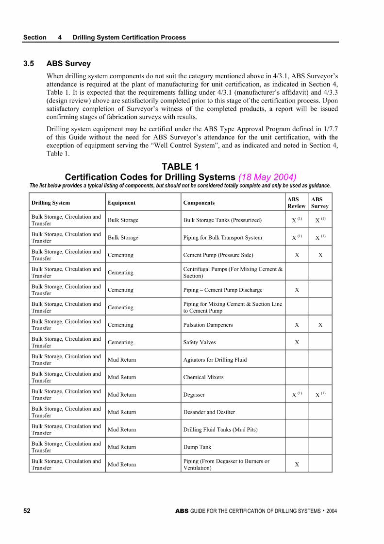
Section 4 Drilling System Certification Process
52 ABS GUIDE FOR THE CERTIFICATION OF DRILLING SYSTEMS . 2004
3.5 ABS Survey When drilling system components do not suit the category mentioned above in 4/3.1, ABS Surveyor’s attendance is required at the plant of manufacturing for unit certification, as indicated in Section 4, Table 1. It is expected that the requirements falling under 4/3.1 (manufacturer’s affidavit) and 4/3.3 (design review) above are satisfactorily completed prior to this stage of the certification process. Upon satisfactory completion of Surveyor’s witness of the completed products, a report will be issued confirming stages of fabrication surveys with results.
Drilling system equipment may be certified under the ABS Type Approval Program defined in 1/7.7 of this Guide without the need for ABS Surveyor’s attendance for the unit certification, with the exception of equipment serving the “Well Control System”, and as indicated and noted in Section 4, Table 1.
TABLE 1 Certification Codes for Drilling Systems (18 May 2004)
The list below provides a typical listing of components, but should not be considered totally complete and only be used as guidance.
Drilling System Equipment Components ABS Review
ABS Survey
Bulk Storage, Circulation and Transfer Bulk Storage Bulk Storage Tanks (Pressurized) X (1) X (1)
Bulk Storage, Circulation and Transfer Bulk Storage Piping for Bulk Transport System X (1) X (1)
Bulk Storage, Circulation and Transfer Cementing Cement Pump (Pressure Side) X X
Bulk Storage, Circulation and Transfer Cementing Centrifugal Pumps (For Mixing Cement &
Suction)
Bulk Storage, Circulation and Transfer Cementing Piping – Cement Pump Discharge X
Bulk Storage, Circulation and Transfer Cementing Piping for Mixing Cement & Suction Line
to Cement Pump
Bulk Storage, Circulation and Transfer Cementing Pulsation Dampeners X X
Bulk Storage, Circulation and Transfer Cementing Safety Valves X
Bulk Storage, Circulation and Transfer Mud Return Agitators for Drilling Fluid
Bulk Storage, Circulation and Transfer Mud Return Chemical Mixers
Bulk Storage, Circulation and Transfer Mud Return Degasser X (1) X (1)
Bulk Storage, Circulation and Transfer Mud Return Desander and Desilter
Bulk Storage, Circulation and Transfer Mud Return Drilling Fluid Tanks (Mud Pits)
Bulk Storage, Circulation and Transfer Mud Return Dump Tank
Bulk Storage, Circulation and Transfer Mud Return Piping (From Degasser to Burners or
Ventilation) X
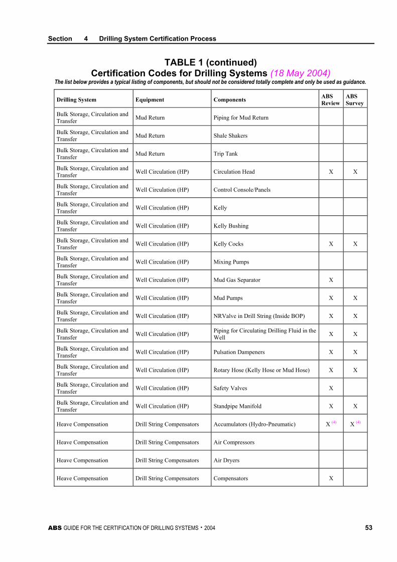
Section 4 Drilling System Certification Process
ABS GUIDE FOR THE CERTIFICATION OF DRILLING SYSTEMS . 2004 53
TABLE 1 (continued) Certification Codes for Drilling Systems (18 May 2004)
The list below provides a typical listing of components, but should not be considered totally complete and only be used as guidance.
Drilling System Equipment Components ABS Review
ABS Survey
Bulk Storage, Circulation and Transfer Mud Return Piping for Mud Return
Bulk Storage, Circulation and Transfer Mud Return Shale Shakers
Bulk Storage, Circulation and Transfer Mud Return Trip Tank
Bulk Storage, Circulation and Transfer Well Circulation (HP) Circulation Head X X
Bulk Storage, Circulation and Transfer Well Circulation (HP) Control Console/Panels
Bulk Storage, Circulation and Transfer Well Circulation (HP) Kelly
Bulk Storage, Circulation and Transfer Well Circulation (HP) Kelly Bushing
Bulk Storage, Circulation and Transfer Well Circulation (HP) Kelly Cocks X X
Bulk Storage, Circulation and Transfer Well Circulation (HP) Mixing Pumps
Bulk Storage, Circulation and Transfer Well Circulation (HP) Mud Gas Separator X
Bulk Storage, Circulation and Transfer Well Circulation (HP) Mud Pumps X X
Bulk Storage, Circulation and Transfer Well Circulation (HP) NRValve in Drill String (Inside BOP) X X
Bulk Storage, Circulation and Transfer Well Circulation (HP) Piping for Circulating Drilling Fluid in the
Well X X
Bulk Storage, Circulation and Transfer Well Circulation (HP) Pulsation Dampeners X X
Bulk Storage, Circulation and Transfer Well Circulation (HP) Rotary Hose (Kelly Hose or Mud Hose) X X
Bulk Storage, Circulation and Transfer Well Circulation (HP) Safety Valves X
Bulk Storage, Circulation and Transfer Well Circulation (HP) Standpipe Manifold X X
Heave Compensation Drill String Compensators Accumulators (Hydro-Pneumatic) X (4) X (4)
Heave Compensation Drill String Compensators Air Compressors
Heave Compensation Drill String Compensators Air Dryers
Heave Compensation Drill String Compensators Compensators X
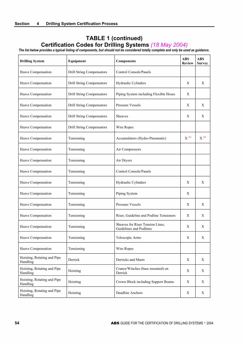
Section 4 Drilling System Certification Process
54 ABS GUIDE FOR THE CERTIFICATION OF DRILLING SYSTEMS . 2004
TABLE 1 (continued) Certification Codes for Drilling Systems (18 May 2004)
The list below provides a typical listing of components, but should not be considered totally complete and only be used as guidance.
Drilling System Equipment Components ABS Review
ABS Survey
Heave Compensation Drill String Compensators Control Console/Panels
Heave Compensation Drill String Compensators Hydraulic Cylinders X X
Heave Compensation Drill String Compensators Piping System including Flexible Hoses X
Heave Compensation Drill String Compensators Pressure Vessels X X
Heave Compensation Drill String Compensators Sheaves X X
Heave Compensation Drill String Compensators Wire Ropes
Heave Compensation Tensioning Accumulators (Hydro-Pneumatic) X (4) X (4)
Heave Compensation Tensioning Air Compressors
Heave Compensation Tensioning Air Dryers
Heave Compensation Tensioning Control Console/Panels
Heave Compensation Tensioning Hydraulic Cylinders X X
Heave Compensation Tensioning Piping System X
Heave Compensation Tensioning Pressure Vessels X X
Heave Compensation Tensioning Riser, Guideline and Podline Tensioners X X
Heave Compensation Tensioning Sheaves for Riser Tension Lines, Guidelines and Podlines X X
Heave Compensation Tensioning Telescopic Arms X X
Heave Compensation Tensioning Wire Ropes
Hoisting, Rotating and Pipe Handling Derrick Derricks and Masts X X
Hoisting, Rotating and Pipe Handling Hoisting Cranes/Winches (base mounted) on
Derrick X X
Hoisting, Rotating and Pipe Handling Hoisting Crown Block including Support Beams X X
Hoisting, Rotating and Pipe Handling Hoisting Deadline Anchors X X
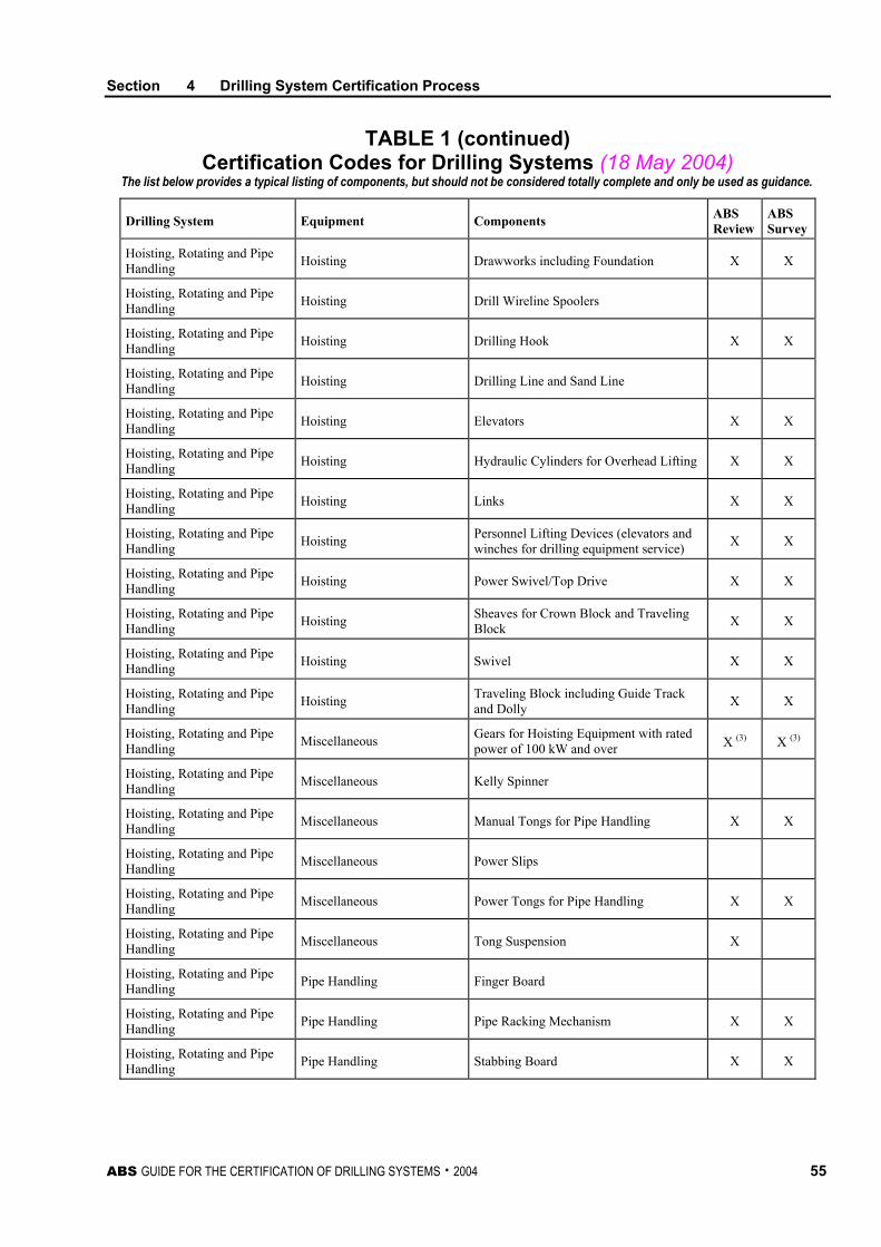
Section 4 Drilling System Certification Process
ABS GUIDE FOR THE CERTIFICATION OF DRILLING SYSTEMS . 2004 55
TABLE 1 (continued) Certification Codes for Drilling Systems (18 May 2004)
The list below provides a typical listing of components, but should not be considered totally complete and only be used as guidance.
Drilling System Equipment Components ABS Review
ABS Survey
Hoisting, Rotating and Pipe Handling Hoisting Drawworks including Foundation X X
Hoisting, Rotating and Pipe Handling Hoisting Drill Wireline Spoolers
Hoisting, Rotating and Pipe Handling Hoisting Drilling Hook X X
Hoisting, Rotating and Pipe Handling Hoisting Drilling Line and Sand Line
Hoisting, Rotating and Pipe Handling Hoisting Elevators X X
Hoisting, Rotating and Pipe Handling Hoisting Hydraulic Cylinders for Overhead Lifting X X
Hoisting, Rotating and Pipe Handling Hoisting Links X X
Hoisting, Rotating and Pipe Handling Hoisting Personnel Lifting Devices (elevators and
winches for drilling equipment service) X X
Hoisting, Rotating and Pipe Handling Hoisting Power Swivel/Top Drive X X
Hoisting, Rotating and Pipe Handling Hoisting Sheaves for Crown Block and Traveling
Block X X
Hoisting, Rotating and Pipe Handling Hoisting Swivel X X
Hoisting, Rotating and Pipe Handling Hoisting Traveling Block including Guide Track
and Dolly X X
Hoisting, Rotating and Pipe Handling Miscellaneous Gears for Hoisting Equipment with rated
power of 100 kW and over X (3) X (3)
Hoisting, Rotating and Pipe Handling Miscellaneous Kelly Spinner
Hoisting, Rotating and Pipe Handling Miscellaneous Manual Tongs for Pipe Handling X X
Hoisting, Rotating and Pipe Handling Miscellaneous Power Slips
Hoisting, Rotating and Pipe Handling Miscellaneous Power Tongs for Pipe Handling X X
Hoisting, Rotating and Pipe Handling Miscellaneous Tong Suspension X
Hoisting, Rotating and Pipe Handling Pipe Handling Finger Board
Hoisting, Rotating and Pipe Handling Pipe Handling Pipe Racking Mechanism X X
Hoisting, Rotating and Pipe Handling Pipe Handling Stabbing Board X X
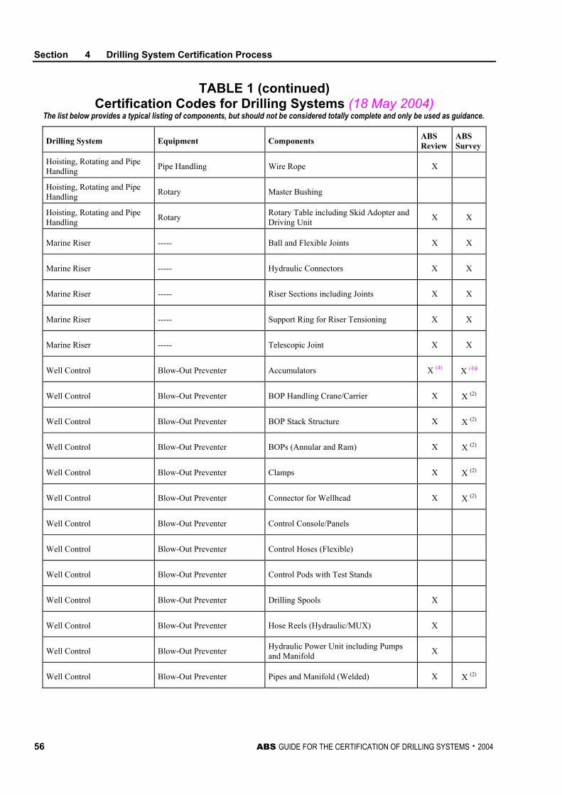
Section 4 Drilling System Certification Process
56 ABS GUIDE FOR THE CERTIFICATION OF DRILLING SYSTEMS . 2004
TABLE 1 (continued) Certification Codes for Drilling Systems (18 May 2004)
The list below provides a typical listing of components, but should not be considered totally complete and only be used as guidance.
Drilling System Equipment Components ABS Review
ABS Survey
Hoisting, Rotating and Pipe Handling Pipe Handling Wire Rope X
Hoisting, Rotating and Pipe Handling Rotary Master Bushing
Hoisting, Rotating and Pipe Handling Rotary Rotary Table including Skid Adopter and
Driving Unit X X
Marine Riser ----- Ball and Flexible Joints X X
Marine Riser ----- Hydraulic Connectors X X
Marine Riser ----- Riser Sections including Joints X X
Marine Riser ----- Support Ring for Riser Tensioning X X
Marine Riser ----- Telescopic Joint X X
Well Control Blow-Out Preventer Accumulators X (4) X (4))
Well Control Blow-Out Preventer BOP Handling Crane/Carrier X X (2)
Well Control Blow-Out Preventer BOP Stack Structure X X (2)
Well Control Blow-Out Preventer BOPs (Annular and Ram) X X (2)
Well Control Blow-Out Preventer Clamps X X (2)
Well Control Blow-Out Preventer Connector for Wellhead X X (2)
Well Control Blow-Out Preventer Control Console/Panels
Well Control Blow-Out Preventer Control Hoses (Flexible)
Well Control Blow-Out Preventer Control Pods with Test Stands
Well Control Blow-Out Preventer Drilling Spools X
Well Control Blow-Out Preventer Hose Reels (Hydraulic/MUX) X
Well Control Blow-Out Preventer Hydraulic Power Unit including Pumps and Manifold X
Well Control Blow-Out Preventer Pipes and Manifold (Welded) X X (2)
Section 4 Drilling System Certification Process
ABS GUIDE FOR THE CERTIFICATION OF DRILLING SYSTEMS . 2004 57
TABLE 1 (continued) Certification Codes for Drilling Systems (18 May 2004)
The list below provides a typical listing of components, but should not be considered totally complete and only be used as guidance.
Drilling System Equipment Components ABS Review
ABS Survey
Well Control Blow-Out Preventer Pipes (Unwelded) for Hydraulic Systems
Well Control Blow-Out Preventer Power Package (Acoustic Transportable Emergency Power) X X (2)
Well Control Blow-Out Preventer Test Stump X X (2)
Well Control Choke and Kill Choke and Kill – Chokes/Valves X X (2)
Well Control Choke and Kill Choke and Kill – Manifolds including Chokes, Spools and Valves X X (2)
Well Control Choke and Kill Choke, Kill and Booster Lines – Flexible Hoses X X (2)
Well Control Choke and Kill Choke, Kill and Booster Lines – Piping X X (2)
Well Control Choke and Kill Emergency Circulating Pump (Pressure Side) X X (2)
Well Control Choke and Kill Kill Unit X X (2)
Well Control Diverter Control Console/Panels
Well Control Diverter Diverter House with Annular Valve X X (2)
Well Control Diverter Hydraulic Power Unit including Pumps and Manifold X
Well Control Diverter Piping X X (2)
Well Control Diverter Valves X X (2)
Well Test Miscellaneous Burner Boom X X
Well Test Miscellaneous Burners
Well Test Miscellaneous Flanges, Piping, Unions, Valves, etc.
Well Test Miscellaneous Heat Exchangers
Well Test Miscellaneous Pressure Vessels and Separators
Well Test Miscellaneous Pumps (Other)
Well Test Miscellaneous Pumps for Overhauling of Wells (Pressure Side) X X
Section 4 Drilling System Certification Process
58 ABS GUIDE FOR THE CERTIFICATION OF DRILLING SYSTEMS . 2004
TABLE 1 (continued) Certification Codes for Drilling Systems (18 May 2004)
The list below provides a typical listing of components, but should not be considered totally complete and only be used as guidance.
Drilling System Equipment Components ABS Review
ABS Survey
Well Test Miscellaneous Safety Valves for Miscellaneous Equipment
Miscellaneous Control Drillers Console X
Miscellaneous Electrical Electric Hose Bundle
Miscellaneous Electrical Rotating Machines with rated power of 100 kW and over X (3) X (3)
Notes: 1 Components that fall under Group I systems defined in the ABS Rules for Building and Classing Steel Vessels
will require ABS engineering review or survey, as applicable.
2 ABS Surveyor’s attendance is required for unit certification and the equipment or its components cannot be accepted based only on the ABS Type Approval Program.
3 Components with less than specified rating in the table do not require ABS engineering review or Surveyor’s attendance.
4 (18 May 2004) Seamless accumulators do not require ABS engineering review or Surveyor’s attendance, provided they are certified to ASME Section VIII (or equivalent standard) by an independent recognized third party.
ABS GUIDE FOR THE CERTIFICATION OF DRILLING SYSTEMS . 2004 59
S E C T I O N 5 Drilling System Piping
1 General
This Section contains general requirements for piping and piping system components that form part of the drilling system, as follows:
• Well Test Piping
• High Pressure Mud and Cement Piping
• Choke and Kill Piping
• Diverter Piping
• Bulk Mud and Cement Piping
• Blow-out Preventer Control and Closing Unit Piping
These requirements are to be used for all drilling system piping and in conjunction with the specific requirements contained in Section 3 of this Guide for individual subsystems used for both drilling and ship service. Other auxiliary piping systems such as hydraulic piping, air piping, etc., are to comply with Part 4, Chapter 2 of the MODU Rules.
The manufacturer is to submit for approval to ABS design drawings and calculations for each piping system. Piping design is to conform to ANSI B31.3, API RP14E and other codes and specifications (such as BS 3351), as agreed to by ABS. See 2/7.3 of this Guide.
3 Design Criteria
3.1 Maximum Allowable Working Pressure (MAWP) and Minimum Thickness Piping is to be designed to withstand the maximum stress that could arise from the most severe combination of temperature and pressure. For high pressure ranges not covered by the referenced recognized code, a pipe wall thickness calculation for piping design should use a recognized code procedure.
3.1.1 Allowances The design wall thickness of all piping is to account for:
i) Mill under-tolerances (12.5% of nominal piping thickness, unless otherwise stated in the material specification)
ii) Allowances for threads (if applicable)
iii) Corrosion/erosion allowance (unless an effective coating system is applied)
iv) Bending allowances
Section 5 Drilling System Piping
60 ABS GUIDE FOR THE CERTIFICATION OF DRILLING SYSTEMS . 2004
3.1.2 Service Conditions Further, the piping design is to account for, relative to the fluid being transported, transient vibrational stresses, hydraulic hammer, transient temperature excursions, outside imposed impact forces and pressure pulsations, and low temperature service considerations.
3.3 Fittings, Valves, Connections All piping appurtenances are to meet the applicable piping code and the additional requirements herein.
3.5 Alternative Criteria Consideration may also be given to pipe fitting or valve design justification on the basis of a combined stress criteria with allowable stress intensity levels determined as a function of material yield strength. The extent of nondestructive examination, service temperatures, material ductility and special fabrication methods will also be considered.
Piping elements whose shell dimensions are not specified by a recognized code, design details including dimensional drawings, stress calculations and material data are to be submitted for approval.
3.7 Socket Welds Socket-welding of piping connections intended for corrosive, particularly sour services is to be avoided. All socket-welding connections are to be identified and specially approved by ABS.
3.9 Threaded Connections NPT-threaded screwed connections are not to be used in piping systems with design pressure in excess of 20.7 MPa (3,000 psi). Flared or other ABS-approved screwed connectors may be used in higher-pressure service.
All screwed connections are to be evaluated, considering the following:
• Pipe outer diameter and thread allowance
• Fluid type, corrosion and fluid leakage risk
• Transient excursions of vibration, pulsation and pressure
3.11 Quick Connect Fittings Hammer lock or other quick connect type specialty fittings are to have a rated pressure not less than the pipe system design pressure and are to conform to applicable piping codes or alternative standards.
3.13 Flexible Hoses
3.13.1 Design Hose for rotary or other drilling service below 51.7 MPa (7,500 psi) are to comply with the prototype test specified in API Spec. 7K and be suitable for their intended service (temperature, fluid compatibility, etc.). For higher-pressure hose, see 3/17.5 of this Guide.
3.13.2 Fire Resistance All flexible piping carrying combustible fluids or used in hazardous locations is to be fire-resistant in accordance with U.L. 1114 or other recognized standard.
Section 5 Drilling System Piping
ABS GUIDE FOR THE CERTIFICATION OF DRILLING SYSTEMS . 2004 61
3.13.3 End Connections End connections for flexible piping are to be designed and fabricated to the requirements of 5/3.1 of this Guide.
3.13.4 Isolation Valving is to be provided to isolate potential uncontrolled outflow of flowing medium from flexible piping where a hazard could exist.
3.13.5 Miscellaneous All flexible piping elements are to be accessible for on-site inspection. Expansion joints or bellows in piping systems are to be provided with shields to prevent mechanical damage. Expansion joints or bellows are to be properly aligned and secured.
5 Piping Materials
Toughness. For toughness and traceability requirements, see Section 6 of this Guide.
Composite Materials. Composite materials where used in drilling piping system applications are to be of fire resistant construction and are to be designed and tested to ASME Boiler and Pressure Vessel Code, Section X.

This Page Intentionally Left Blank
ABS GUIDE FOR THE CERTIFICATION OF DRILLING SYSTEMS . 2004 63
S E C T I O N 6 Materials for Drilling Systems and Components
1 General
This Section addresses the considerations to be taken into account in selecting materials for drilling systems and components.
3 Selection of Structural Steels
All materials are to be suitable for their intended service conditions and defined by a recognized standard.
For guidance on the selection of steel for plates, shapes and structural pipe sections, reference is to be made to recognized standards such as API RP 2A, or Part 4, Chapter 1 of the ABS MODU Rules.
Toughness. Where toughness is to be considered in material selection, the toughness testing criteria in the API RP 2A or the Rules for Materials and Welding – Part 2 are to be met for the principal structural components of derricks, masts and burner booms.
Bolts and Nuts. Bolts and nuts are to have corrosion characteristics comparable to the structural elements being joined and are to be manufactured and tested in accordance with recognized material standards.
5 Selection of Drilling Equipment Materials
Materials for load-bearing and pressure-containing elements of drilling equipment are to be selected with due regard to toughness, corrosion resistance and weldability, and are to comply with the following specific criteria:
5.1 Toughness Unless the toughness and all other material requirements of drilling equipment components are in full compliance with an applicable API standard, the following ABS requirements are to be complied with.
Where the design service operational or transient excursion temperature is 0°C (32°F) or below, notch toughness testing of ferritic and martensitic steels subject to tensile stress is generally required. The toughness requirements may be defined in terms of minimum Charpy V-notch (CVN) impact values, as indicated in Section 6, Figure 1 for materials with yield strengths of 65 ksi and below. For materials with yield strengths of above 65 ksi, the lateral expansion opposite the notch is not to be less than 0.015 in. The Charpy V-Notch (CVN) impact tests are generally to be carried out at the minimum design temperature of the component. Test procedures and size, location and orientation of specimens are to be in accordance with the standard applied in design and manufacturing of the drilling equipment.
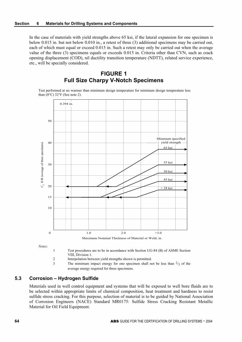
Section 6 Materials for Drilling Systems and Components
64 ABS GUIDE FOR THE CERTIFICATION OF DRILLING SYSTEMS . 2004
In the case of materials with yield strengths above 65 ksi, if the lateral expansion for one specimen is below 0.015 in. but not below 0.010 in., a retest of three (3) additional specimens may be carried out, each of which must equal or exceed 0.015 in. Such a retest may only be carried out when the average value of the three (3) specimens equals or exceeds 0.015 in. Criteria other than CVN, such as crack opening displacement (COD), nil ductility transition temperature (NDTT), related service experience, etc., will be specially considered.
FIGURE 1 Full Size Charpy V-Notch Specimens
Test performed at no warmer than minimum design temperature for minimum design temperature less than (0°C) 32°F (See note 2).
10
15
20
30
40
50
0 1.0 2.0 >3.0
< 38 ksi
45 ksi
50 ksi
55 ksi
65 ksi
Minimum specifiedyield strength
0.394 in.
Maximum Nominal Thickness of Material or Weld, in.
Cy, f
t-lb
(ave
rage
of t
hree
spe
cim
ens)
Notes:
1 Test procedures are to be in accordance with Section UG-84 (B) of ASME Section VIII, Division 1.
2 Interpolation between yield strengths shown is permitted. 3 The minimum impact energy for one specimen shall not be less than 2/3 of the
average energy required for three specimens.
5.3 Corrosion – Hydrogen Sulfide Materials used in well control equipment and systems that will be exposed to well bore fluids are to be selected within appropriate limits of chemical composition, heat treatment and hardness to resist sulfide stress cracking. For this purpose, selection of material is to be guided by National Association of Corrosion Engineers (NACE) Standard MR0175: Sulfide Stress Cracking Resistant Metallic Material for Oil Field Equipment.
Section 6 Materials for Drilling Systems and Components
ABS GUIDE FOR THE CERTIFICATION OF DRILLING SYSTEMS . 2004 65
5.5 Corrosion – Marine Atmosphere External and internal steel surfaces exposed to salt water/salt air environment are to be suitably coated or cathodically protected. Where the corrosion rate can be reliably predicted, a calculated corrosion allowance may be used. In the absence of a reliable corrosion rate, 0.125 mm. (0.005 in.) is to be applied on each surface.
5.7 Stress To determine the suitability of a material to withstand design stresses, the ultimate tensile strength, yield strength, elongation and reduction of area are to be specified.
7 Fabrication Considerations
7.1 Welding Generally, weldments subject to hydrogen sulfide service are not to exceed a hardness of 22 Rockwell C in weld metal or heat affected zone (see NACE MR0175). All welding is to comply with Section 7 of this Guide.
7.3 Forming In general, for steel components, forming at temperatures around 205°C (400°F) is to be avoided. Where degradation of properties is unavoidable, complete post forming heat treatment may be required.
Suitable supporting data is to be provided to indicate compliance with the specified properties. For materials with specified toughness properties that are to be formed beyond 3% strain* on the outer fiber, data are to be provided indicating that the toughness properties meet the minimum requirements after forming. After straining, specimens used in toughness tests are to be subjected to an artificial aging treatment of 288°C (550°F) for one hour. * For details, see 2-4-1/3.13 of the ABS Rules for Materials and Welding.
9 Primary Product Form
9.1 General Wrought and cast products are to be procured in accordance with written specifications that, in addition to property requirements, specify the frequency, location, orientation and types of test specimens. Specific nondestructive examination requirements may be required for some product forms. See 7/11.3 of this Guide.
9.3 Rolled Products Plates, shapes and bars may be supplied in the as rolled, thermo-mechanically processed, normalized, or quenched and tempered condition, depending on the intended application.
9.5 Forgings Forged products are to be supplied in a fully worked condition to assure a wrought microstructure and internal soundness. A forging reduction ratio of not less than 3:1 will be considered as meeting this requirement. Where a net change in the cross section does not occur during a portion of the forging operation, the hot working ratio representing that portion will be evaluated as a complement to the forging reduction ratio.
Section 6 Materials for Drilling Systems and Components
66 ABS GUIDE FOR THE CERTIFICATION OF DRILLING SYSTEMS . 2004
9.7 Castings In general, cast products are to be supplied in a heat-treated condition. Samples for testing are to be taken from integrally cast coupons or appropriately designed separately cast coupons. These coupons are to be subjected to the same heat treatment as the casting.
11 Sealing Materials
11.1 Elastomeric Sealants Materials used for sealing are to be suitable for the intended operating pressures and temperatures. Age-sensitive materials for critical components are to have a defined storage life and be identified in storage as to month and year of manufacture.
11.3 Ring Joint Gaskets Ring joint gaskets are to be of soft iron, low carbon steel or stainless steel, as required by the design standard. Gaskets that are coated with a protective coating material such as fluorocarbon or rubber for shipment and storage are to have the coatings removed prior to installation.
13 Materials and Traceability
13.1 Materials All materials used for pressure-retaining and major load-bearing parts are to be furnished with documentation that states the process of manufacture and heat treatment, together with chemical analysis and tests that were applied according to recognized standards. Test coupons are required for each heat treatment for verification of mechanical properties to the manufacturer’s written specification and/or industry standards.
13.3 Traceability Traceability through the manufacturing process shall be documented on major load-bearing and pressure-retaining parts. The manufacturers are responsible for maintaining this documentation on file and upon request are to provide this information to ABS.
The traceability documentation shall include:
i) Certified Materials Test Report
• Chemical and mechanical properties for each heat
• Heat treatment temperatures and time at temperature
• Charpy impact values and temperatures
• Hardness test readings (as applicable to NACE MR0175)
ii) Manufacturing Processes
• Welding records with all approved qualifications • Post weld heat treatment • NDT results • Hardness test results (as applied to NACE MR0175) • Dimensional check results • Hydrostatic pressure tests
ABS GUIDE FOR THE CERTIFICATION OF DRILLING SYSTEMS . 2004 67
S E C T I O N 7 Welding and Nondestructive Examination
1 General
All welds in the pressure boundary of pressure-retaining components and piping systems and welds in load-carrying mechanical and structural components are to be made using approved welding procedures by qualified welders and are to be inspected utilizing approved procedures by qualified technicians.
Critical sections of primary components are to be examined for surface and volumetric flaws to the extent specified in the design, but not to a lesser extent than that specified in this Section.
The Surveyor is to be satisfied that all welders and welding operators to be employed in the construction of equipment are properly qualified and experienced in the work proposed. The Surveyor is also to be satisfied as to the employment of a sufficient number of skilled supervisors to ensure a thorough supervision and control of all welding operations. Inspection of welds employing methods outlined in this section is to be carried out to the satisfaction of the Surveyor.
3 Specifications
As applicable, Welding Procedure Specification (WPS) and Nondestructive Examination (NDE) procedures are to be submitted for review as part of the design. Where high-tensile strength or special alloy materials are used, the corresponding Procedure Qualification Record (PQR) for the WPS is also required to be submitted for review.
3.1 Welding Procedure Specification A written Welding Procedure Specification (WPS) is to be prepared in accordance with Section IX of the ASME Boiler and Pressure Vessel Code, or ANSI/AWS D1.1 Structural Welding Code, or equivalent, depending on the component. The WPS is to describe in detail all essential and nonessential variables to the welding process(es) employed in the procedure.
Welding procedure specifications are to be qualified and the Procedure Qualification Record (PQR) documenting the following data is to be made available to the attending Surveyors:
i) Maximum hardness values (for well bore fluid service)
ii) Minimum and average toughness values for weld heat affected zone and weld metal (absorbed energy or lateral expansion, both by Charpy method, where the base metal is required to be impact tested in accordance with Sections 3 or 6 of this Guide.)
iii) Minimum tensile strength
iv) Results from other tests required by the applicable code or standard
Section 7 Welding and Nondestructive Examination
68 ABS GUIDE FOR THE CERTIFICATION OF DRILLING SYSTEMS . 2004
Where welding equipment and consumables have never been used at the manufacturer’s facility, are not compatible or are outside of the essential variable limits defined in the existing WPS or if specifically requested by the attending Surveyor, the WPS is to be qualified by welding qualification procedures in the presence of the Surveyor. The qualification process may require the submittal of relative WPS and supporting PQRs to the Engineering office for review and agreement.
3.3 NDE Procedures NDE procedures are to be specified and the parameters of test specification (method), extent of examination and acceptance criteria are to be submitted for review and be available to the attending Surveyor.
5 Welder/Welding Operator Qualification
Welders and welding operators are to be qualified by qualification tests conducted and evaluated in accordance with the applicable code for each welding process and for each position used in production welding. Welder/welding operator qualification records are to be made available to the Surveyor.
7 Qualification of Nondestructive Technicians
The manufacturers are to certify that personnel performing and evaluating the nondestructive examinations have been qualified and certified in accordance with their employer’s written practice. American Society for Nondestructive Testing (ASNT) Recommended Practice No. SNT-TC-1A or equivalent is to be used as a guideline for employers to establish their written practice for qualification and certification of their personnel. Certification documents of NDE technicians are to be made available to the Surveyor.
9 Post Weld Heat Treatment
Accurate records of all heat treatments during fabrication, including rates of heating and cooling, hold time and soaking temperature are to be made available to the Surveyor. Alternative methods of stress relief will be subject to special consideration by the Bureau where post-weld heat treatment is not a requirement of the applicable construction code.
11 Nondestructive Examination
All weldments and other critical sections covered under Subsection 7/1 of this Guide are to be subjected to 100% visual examination and nondestructive examination for surface and volumetric defects in accordance with this Guide or the relevant code. Examinations are to be carried out after any postweld heat treatment.
11.1 Extent of Examination for Materials and Welds i) All highly stressed areas of forgings and castings of primary components used in well control
are to be examined for flaws by methods capable of detecting and sizing significant internal defects. Methods to detect surface flaws are also to be used in special applications. Substantiation is to be provided for areas exempted from examination in the terms of stress levels, quality control procedures at the foundry, forming or casting procedures, or documented historical data.
ii) Repair welds are to be subject to 100% surface NDE.
Section 7 Welding and Nondestructive Examination
ABS GUIDE FOR THE CERTIFICATION OF DRILLING SYSTEMS . 2004 69
iii) All welds of structural members considered special are to be inspected 100% by the ultrasonic or radiographic method. Twenty percent of all welds of structural members considered primary are to be inspected by the ultrasonic or radiographic method. Welds of structural members considered to be secondary are to be inspected by the ultrasonic or radiographic method on a random basis. In locations where ultrasonic test results are not considered reliable, the use of magnetic-particle or dye-penetrant inspection as a supplement to ultrasonic inspection is to be conducted.
iv) Welds of major load-carrying or pressure-retaining components are to be examined by nondestructive methods capable of detecting and sizing significant surface and internal defects.
11.3 Methods and Acceptance Criteria The methods for performing the nondestructive examination and the acceptance standards to be used for each type of examination, in general, are to be in accordance with the following, as applicable:
11.3.1 Magnetic Particle Examination Methods – ASME Boiler and Pressure Vessel Code Section V Article 7: “Magnetic Particle Examination.” ASTM E709: “Standard Recommended Practice for Magnetic Particle Examination.”
Acceptance Criteria – Section VIII, Appendix 4, ASME Boiler and Pressure Vessel Code.
11.3.2 Liquid Penetrant Examination Methods – ASME Boiler and Pressure Vessel Code Section V Article 6: “Liquid Penetrant Examination.” ASTM E165: “Standard Practice for Liquid Penetrant Inspection.”
Acceptance Criteria – ASME Boiler and Pressure Vessel Code, Section VIII, Division 1, Appendix 8, “Methods for Liquid Penetrant Examination (PT).” ANSI/AWS D1.1 “Structural Welding Code” 9.25 “Quality of Welds.”
11.3.3 Radiographic Examination Methods – ASME Boiler and Pressure Vessel Code Section V Article 2: “Radiographic Examination.” ASTM E94: “Standard Practice for Radiographic Testing.” ASTM E446: “Standard Reference Radiographs for Steel Castings up to 2 in. in Thickness.” ASTM E186: “Standard Reference Radiographs for Heavy Walled (2 to 4.5 in.) (51 to 114 mm) Steel Castings.” ASTM E280: “Standard Reference Radiographs for (4.5 to 12 in.) (114 to 305 mm) Steel Castings.”
Acceptance Criteria – ASME Boiler and Pressure Vessel Code, Section VIII, Appendix 4, “Rounded Indications Charts Acceptance Standard for Radiographically Determined Rounded Indications in Welds.” ANSI/AWS D1.1 “Structural Welding Code” 9.25 “Quality of Welds.”
11.3.4 Ultrasonic Examination Methods – ASME Boiler and Pressure Vessel Code Section V, Nondestructive Testing, Article 5: “UT Examination Methods for Materials and Fabrication.” ASTM A388: “Recommended Practice for Ultrasonic Examination of Heavy Steel Forgings.” ASTM E428: “Standard Recommended Practice for Fabrication and Control of Steel Reference Blocks Used in Ultrasonic Inspection.” ASTM A609: “Specification for Ultrasonic Examination for Carbon and Low- Alloy Steel Castings.”
Acceptance Criteria – ASME Boiler and Pressure Vessel Code, Section VIII, Appendix 12, “Ultrasonic Examination of Welds (UT).” ANSI/AWS D1.1 Section 6, Part C, “Ultrasonic Testing of Groove Welds.” API RP-2X “Ultrasonic Examination of Offshore Structural Fabrication and Guidelines for Qualification of Ultrasonic Technicians.”
Section 7 Welding and Nondestructive Examination
70 ABS GUIDE FOR THE CERTIFICATION OF DRILLING SYSTEMS . 2004
11.3.5 Hardness Testing Methods – ASTM 10: “Standard Test Methods for Brinell Hardness of Metallic Materials. ASTM E18: “Standard Test Methods for Rockwell Hardness and Rockwell Superficial Hardness of Metallic Materials.” ASTM E92: “Standard Test Method for Vickers Hardness of Metallic Materials.”
Acceptance Criteria – NACE MR0175: “Sulfide Stress Cracking Resistant Metallic Materials for Oilfield Equipment.”
13 Record Retention
The manufacturer shall maintain the following records after completion, and these records are to be made available to the Surveyor upon request:
i) Weld Procedure Specification
ii) Procedure Qualification Records
iii) Welder/welding operator performance test records, including the date and test results and identification of work assigned to each welder
iv) A record providing traceability and capable of identifying the welders who have carried out welding on particular part
v) Qualification records for all personnel performing nondestructive examinations and evaluating results of examination
vi) Nondestructive Examination records, including radiographs (the manufacturer is to provide a suitable viewer to properly illuminate radiographs)
ABS GUIDE FOR THE CERTIFICATION OF DRILLING SYSTEMS . 2004 71
S E C T I O N 8 Surveys at Vendor’s Plant and During Installation
1 General
This Section pertains to surveys of drilling system components at vendor’s plant of manufacture and their installation onboard the drilling units for system build-up and completion for final trials prior to commencement of drilling operations.
3 Surveys at Manufacture and During Assembly
When the Surveyor’s attendance at the shop of the manufacturer and at the assembly site is required by the applicable ABS Rules or this Guide, the manufactured/assembled system components will be verified to be satisfactorily in compliance with a recognized standard such as the American Petroleum Institute (API) and as stated in the manufacturer’s submitted affidavit. See Section 4, Table 1 of this Guide for component fabrication requirements.
Unless the facility/vendor has ABS Product Quality Assurance Certificate, ABS Surveyor’s attendance is required, typically for the following purposes:
i) To confirm that the facilities to manufacture, fabricate or repair drilling system components have and maintain an effective quality control program effectively covering design, procurement, manufacturing and testing, as applicable, and meeting the requirements of a recognized standard applied to their product
ii) To qualify or verify welder’s qualifications to the extent deemed necessary by the attending ABS Surveyor
iii) To qualify or verify welding procedure specifications and corresponding weld procedure qualification records to the extent deemed necessary by the attending ABS Surveyor
iv) To verify material certificates/documentation
v) To survey fit-up prior to major weldments
vi) To survey final weldments
vii) To witness, as far as deemed necessary, nondestructive examination tests of welds and to review records of nondestructive examinations
viii) To review records of post-weld heat treatment, in particular for piping subjected to pressurized sour service and subject to NACE MR0175 requirements
ix) To verify dimensions are the same as shown on approved drawings
x) To check dimensional tolerances and alignment of mating surfaces
xi) To witness pressure and/or proof-load testing of equipment components and as a unit, as applicable and as called for in the fabrication procedures
Section 8 Surveys at Vendor’s Plant and During Installation
72 ABS GUIDE FOR THE CERTIFICATION OF DRILLING SYSTEMS . 2004
xii) To witness final testing and functional testing of subassemblies and completed units, as called for in the fabrication procedures
xiii) To verify all purged and pressurized systems, motor controllers, SCR banks, consoles and instrumentation and control panels are in compliance with approved drawings
xiv) To carry out other inspections as agreed upon during prefabrication meeting.
Materials Test Report (MTR) of the following components is to be made available to the attending Surveyor during the manufacturing process:
i) Materials of main pressure-retaining parts of valves, including safety valves that have flanged or screwed ends or other specialty fittings
ii) All screwed fittings and bolts for fastening
iii) All other piping, valves and fittings with a design temperature less than 180°C (356°F) or a design pressure less than 19.6 KPa (290 psig).
The above components include, but shall not be limited to, the main pressure-retaining parts of valves with welded ends or components joined by welding if used at temperatures or pressures equal to 180°C (356°F) or 19.6 KPa (290 psig).
3.1 Vendor Coordination Program All major projects shall be coordinated through the ABS Vendor Coordination Program to assist the flow of the certification processes. In such cases, an electronic database reflecting the contents of Section 4, Table 1 of this Guide will be made available to all key personnel of the Owner, Manufacturer and Engineers and Surveyors of this Bureau. Upon completion of each task contained in the Table, corresponding database cells are to be filled out by ABS users. The completed database is to be documented as part of final CDS certification of the drilling unit.
5 Surveys During Installation Onboard
The following surveys are to be carried out by ABS Surveyors on systems during installation and testing.
i) Piping systems are to be visually examined, nondestructively examined and pressure tested, as required by the ABS MODU Rules or applicable API Codes.
ii) Pressure tests conducted on Class I (refer to ABS Steel Vessel Rules 4-6-1/Table 1) piping systems should preferably be recorded on test charts for the duration of their tests. Minimum time for holding pressure is to be 15 minutes.
iii) All pressure relief and safety valves are to be tested.
iv) Installed choke and kill systems are to be pressure-tested at rated working pressure and also subjected to a low-pressure test at 2.07 MPa (300 psi). Applicable performance tests are to be carried out.
v) Mud pump operational test is to be carried out.
vi) Drawworks, blocks and associated equipment are to be performance-tested.
vii) All lifting appliances that are part of the drilling system certification are to be load-tested to their design load capacity.
viii) All drilling systems and equipment are to be checked for proper operation.
ix) Control system and shutdowns are to be tested to the satisfaction of the Surveyor.
Section 8 Surveys at Vendor’s Plant and During Installation
ABS GUIDE FOR THE CERTIFICATION OF DRILLING SYSTEMS . 2004 73
x) All wiring and electrical connections are to be checked for continuity and proper workmanship.
xi) Database developed and completed during construction is to be verified for correctness, amended as required, and endorsed as being part of the on-board ABS documentation, and used as long as the drilling system is maintained under ABS Certification.

This Page Intentionally Left Blank
ABS GUIDE FOR THE CERTIFICATION OF DRILLING SYSTEMS . 2004 75
S E C T I O N 9 Surveys After Construction and Maintenance of Class
1 General
The provisions of this Section are requirements for the maintenance of certification of the drilling systems. These requirements are in addition to the provisions noted in other ABS Rules such as Part 5 of the Rules for Building and Classing Mobile Offshore Drilling Units.
When ABS is authorized to perform surveys on behalf of a governmental authority, or when requested by the Owner, items as specified by the governmental authority or Owner will be surveyed. Reports indicating the results of such surveys will be issued.
For purposes of this Section, the commissioning date of the drilling system will be the date on which a Surveyor issues an Interim Class Certificate for the drilling unit with the CDS notation.
3 Surveys Onshore and Issuance of Release Notes
During operation of the drilling unit when parts of the certified drilling system components are returned ashore for maintenance, repair or modification purposes, it is the responsibility of the Owner to inform Surveyors of the scope of work at the shore facility/plant. Surveyors are to attend the facility/plant for all required function, load and/or pressure testing carried out on the drilling system components prior to its release back offshore to the drilling unit. Tests conducted should follow guidelines outlined in API or equivalent.
Upon satisfactory completion of tests and visual examination, a “Release Note” (RN) shall be issued by the attending Surveyor, subject to satisfactory installation of the component on the drilling unit and examination of the component during the forthcoming Annual Survey. See Appendix 3 of this Guide for a sample copy of the “Release Note” to be issued by Surveyors. All RNs are to be maintained onboard the drilling unit as part of the Owner’s maintenance record and for verification by the attending Surveyor during classification surveys of the unit.
5 Survey of Drilling Systems
5.1 Survey Intervals and Maintenance Manuals/Records An annual survey of the drilling systems is to be carried out by a Surveyor within three months either way of each annual anniversary date of the initial certification survey.
A special survey of the drilling system is to be carried out within five years of the initial certification survey and at five-year intervals thereafter.
Required surveys are to be completed within three (3) months of their due dates, unless extended by agreement with the Bureau. Any part of the drilling system may be offered for survey prior to the due date when so desired, in which case, the survey will be credited as of that date.
Section 9 Surveys After Construction and Maintenance of Class
76 ABS GUIDE FOR THE CERTIFICATION OF DRILLING SYSTEMS . 2004
Maintenance records are to be kept and made available for review by the attending Surveyor. The maintenance records will be reviewed to establish the scope and content of the required Annual and Special Periodical Surveys that are to be carried out by a Surveyor. During the service life of the drilling system components, maintenance records are to be updated on a continuing basis. The Owner is to inform the Bureau of any changes to the maintenance procedures and their frequencies as may be caused, for example, by changes or additions to the original drilling equipment. The Surveyor may determine during the periodic survey if the changes are sufficient to warrant review by the ABS Engineering staff.
A maintenance manual for all drilling systems is to be prepared and submitted for review. This manual is to form the basis for annual and special surveys and it is to at least provide all of the requirements contained in 9/5.3 and 9/5.5.
5.3 Annual Surveys (1 April 2004) At each Annual Survey, the Surveyor is to verify the effectiveness of various systems and components by visual examination and testing, as appropriate. As a minimum, the following is to be carried out to the satisfaction of the attending Surveyor:
i) Review of Owner’s maintenance manual and relevant logs/records to confirm that a suitable maintenance program has been followed, periodical testing requirements have been carried out and that any repairs, reconditioning or renewals of well control equipment, BOP controls, riser system, pressure vessels, electrical systems/equipment drilling hoisting system or lifting devices were carried out according to the applicable standards and the requirements of this Guide.
ii) Review of ABS-issued RNs since initial or last Annual Survey, and examination of these components to extent deemed necessary by the attending Surveyor.
iii) Review of ABS Drilling System Database for approved changes made to the drilling system components, and examination of these components to the extent deemed necessary by the attending Surveyor.
iv) Exposed surfaces of the derrick, drilling hoisting systems, lifting devices, burner booms, stabbing boards, racking platforms and drilling equipment foundations shall be examined and placed in satisfactory condition, as found necessary. The inspection of the derrick and related structural members will include the following:
• The general condition of the structure, especially bent, missing or abraded parts and lost corrosion protection coatings.
• Tightness of bolts.
• Condition of wire ropes and fittings.
v) Examination of all mounting hardware and the structure of base-mounted winches and other lifting devices. Magnetic Particle Inspection (MPI) may be carried out as deemed necessary by the attending Surveyor.
vi) General external examination so far as accessible of the items noted in 1/7.3 of this Guide for damage, excess corrosion, fracturing or malfunctions.
vii) Protective covers, insulation, shrouds and protective guards around moving parts are to be found in place and in functional condition.
viii) Derrick walkways and ladders, drill floor and drill system machinery spaces to be surveyed with particular attention to fire and explosion hazards and confirmation that emergency escape routes are not blocked.
ix) External examination of pressure vessels and their appurtenances, including safety devices, foundations, controls, relieving gear, piping systems, flexible hoses, insulation and gauges.
Section 9 Surveys After Construction and Maintenance of Class
ABS GUIDE FOR THE CERTIFICATION OF DRILLING SYSTEMS . 2004 77
x) Examination of safety shutdown devices.
xi) General examination of all electrical and instrumentation systems, including protective devices and cable supports.
xii) Examination of mud and cement systems.
xiii) Examination of the BOP test log and maintenance records.
5.5 Special Periodical Surveys (1 April 2004) The Special Periodical Survey is to include all items listed under the Annual Survey, and, in addition, the following is to be carried out to the satisfaction of the attending Surveyor:
i) Review of Owner’s maintenance records to verify periodical testing requirements have been carried out and that any repairs, reconditioning or renewals of well control equipment, BOP controls, riser system, pressure vessels, electrical systems/equipment drilling hoisting system or lifting devices were carried out according to the applicable standards and the requirements of this Guide.
ii) Review of ABS-issued RNs since last Annual Survey, and examination of these components to the extent deemed necessary by the attending Surveyor.
iii) Review of ABS Drilling System Database for approved changes made to the drilling system components, and examination of these components to the extent deemed necessary by the attending Surveyor.
iv) Internal examination and/or thickness gauging of pressure vessels and pressure-retaining components, testing of relief valves and pressure piping systems, as considered necessary by the Surveyor.
v) Hydrostatic testing of pressure vessels and other pressure-retaining components related to the drilling system to their MAWP.
vi) Hydrostatic testing of drilling system piping systems and flexible hoses to their MAWP.
vii) Examination and check of insulation resistance of motors that are part of the drilling system.
viii) Examination of rotating drilling machinery to verify suitable operation, free from excessive vibration.
ix) The blow-out preventer shall be subjected to a complete performance test and pressure tested to its MAWP.
x) Examination of mud and cement pump fluid ends.
xi) Functional testing of derrick gear, drilling hoisting systems and derrick floor lifting devices.
xii) Close examination of the condition of welded joints on the derrick and associated structure, including thickness gaugings or nondestructive testing of any suspect areas noted by the attending Surveyor.
5.7 Continuous Survey Program A continuous inspection program may be arranged with the Bureau whereby all required surveys are carried out on a continuing basis within a five-year cycle.
5.9 Survey Based on Preventative Maintenance Techniques A properly conducted preventative maintenance/condition-monitoring plan may be credited as satisfying the requirements of Special Continuous Survey. This plan must be in accordance with Appendix 7-A-14 “Guide for Survey Based on Preventative Maintenance Techniques” of the Rules for Survey After Construction – Part 7.
Section 9 Surveys After Construction and Maintenance of Class
78 ABS GUIDE FOR THE CERTIFICATION OF DRILLING SYSTEMS . 2004
5.11 Surveys Using Risk-based Techniques A properly conducted Risk-based Inspection plan or Reliability-centered Maintenance Plan may be credited as satisfying requirements of Special Continuous Survey. The plan must be in accordance with the ABS Guide for Surveys Using Risk-based Inspection for the Offshore Industry or ABS Guide for Surveys Based on Reliability-Centered Maintenance.
7 Modifications, Damage and Repairs
When it is intended to carry out any modifications to the machinery, piping, equipment, etc., which may affect certification, the details of such modifications are to be submitted for approval and the work is to be carried out to the satisfaction of the Surveyor.
When a system certified with the Bureau has suffered any damage to machinery, piping or equipment, etc. which may affect certification, the Bureau is to be notified and the damage inspected by a Surveyor.
If a certified drilling system suffers any damage to its components, the Bureau is to be notified and the damage examined by a Surveyor. Details of intended repairs are to be submitted for approval, and the work is to be carried out to the satisfaction of the attending Surveyor.
Where component parts suffer a premature or unexpected failure, and are subsequently repaired or replaced without Surveyor attendance, details of the failure, including the damaged parts where practicable, are to be retained onboard for examination by the Surveyor during the next scheduled survey/visit. Alternatively, the component(s) may be taken ashore for examination and testing, as required. If failures are deemed to be a result of inadequate or inappropriate maintenance, the maintenance manual is to be amended and resubmitted for approval.
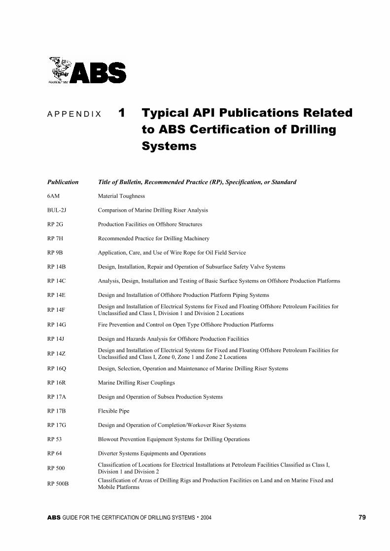
ABS GUIDE FOR THE CERTIFICATION OF DRILLING SYSTEMS . 2004 79
A P P E N D I X 1 Typical API Publications Related to ABS Certification of Drilling Systems
Publication Title of Bulletin, Recommended Practice (RP), Specification, or Standard
6AM Material Toughness
BUL-2J Comparison of Marine Drilling Riser Analysis
RP 2G Production Facilities on Offshore Structures
RP 7H Recommended Practice for Drilling Machinery
RP 9B Application, Care, and Use of Wire Rope for Oil Field Service
RP 14B Design, Installation, Repair and Operation of Subsurface Safety Valve Systems
RP 14C Analysis, Design, Installation and Testing of Basic Surface Systems on Offshore Production Platforms
RP 14E Design and Installation of Offshore Production Platform Piping Systems
RP 14F Design and Installation of Electrical Systems for Fixed and Floating Offshore Petroleum Facilities for Unclassified and Class I, Division 1 and Division 2 Locations
RP 14G Fire Prevention and Control on Open Type Offshore Production Platforms
RP 14J Design and Hazards Analysis for Offshore Production Facilities
RP 14Z Design and Installation of Electrical Systems for Fixed and Floating Offshore Petroleum Facilities for Unclassified and Class I, Zone 0, Zone 1 and Zone 2 Locations
RP 16Q Design, Selection, Operation and Maintenance of Marine Drilling Riser Systems
RP 16R Marine Drilling Riser Couplings
RP 17A Design and Operation of Subsea Production Systems
RP 17B Flexible Pipe
RP 17G Design and Operation of Completion/Workover Riser Systems
RP 53 Blowout Prevention Equipment Systems for Drilling Operations
RP 64 Diverter Systems Equipments and Operations
RP 500 Classification of Locations for Electrical Installations at Petroleum Facilities Classified as Class I, Division 1 and Division 2
RP 500B Classification of Areas of Drilling Rigs and Production Facilities on Land and on Marine Fixed and Mobile Platforms
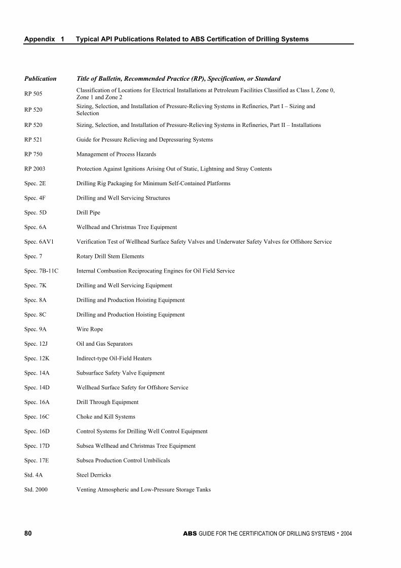
Appendix 1 Typical API Publications Related to ABS Certification of Drilling Systems
80 ABS GUIDE FOR THE CERTIFICATION OF DRILLING SYSTEMS . 2004
Publication Title of Bulletin, Recommended Practice (RP), Specification, or Standard
RP 505 Classification of Locations for Electrical Installations at Petroleum Facilities Classified as Class I, Zone 0, Zone 1 and Zone 2
RP 520 Sizing, Selection, and Installation of Pressure-Relieving Systems in Refineries, Part I – Sizing and Selection
RP 520 Sizing, Selection, and Installation of Pressure-Relieving Systems in Refineries, Part II – Installations
RP 521 Guide for Pressure Relieving and Depressuring Systems
RP 750 Management of Process Hazards
RP 2003 Protection Against Ignitions Arising Out of Static, Lightning and Stray Contents
Spec. 2E Drilling Rig Packaging for Minimum Self-Contained Platforms
Spec. 4F Drilling and Well Servicing Structures
Spec. 5D Drill Pipe
Spec. 6A Wellhead and Christmas Tree Equipment
Spec. 6AV1 Verification Test of Wellhead Surface Safety Valves and Underwater Safety Valves for Offshore Service
Spec. 7 Rotary Drill Stem Elements
Spec. 7B-11C Internal Combustion Reciprocating Engines for Oil Field Service
Spec. 7K Drilling and Well Servicing Equipment
Spec. 8A Drilling and Production Hoisting Equipment
Spec. 8C Drilling and Production Hoisting Equipment
Spec. 9A Wire Rope
Spec. 12J Oil and Gas Separators
Spec. 12K Indirect-type Oil-Field Heaters
Spec. 14A Subsurface Safety Valve Equipment
Spec. 14D Wellhead Surface Safety for Offshore Service
Spec. 16A Drill Through Equipment
Spec. 16C Choke and Kill Systems
Spec. 16D Control Systems for Drilling Well Control Equipment
Spec. 17D Subsea Wellhead and Christmas Tree Equipment
Spec. 17E Subsea Production Control Umbilicals
Std. 4A Steel Derricks
Std. 2000 Venting Atmospheric and Low-Pressure Storage Tanks
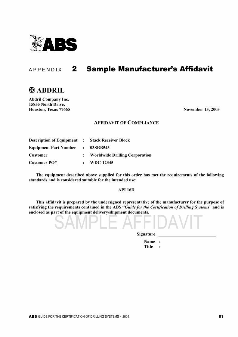
ABS GUIDE FOR THE CERTIFICATION OF DRILLING SYSTEMS . 2004 81
SAMPLE AFFIDAVIT
A P P E N D I X 2 Sample Manufacturer’s Affidavit
À ABDRIL Abdril Company Inc. 15855 North Drive, Houston, Texas 77665 November 13, 2003
AFFIDAVIT OF COMPLIANCE
Description of Equipment : Stack Receiver Block
Equipment Part Number : 03SRB543
Customer : Worldwide Drilling Corporation
Customer PO# : WDC-12345
The equipment described above supplied for this order has met the requirements of the following standards and is considered suitable for the intended use:
API 16D
This affidavit is prepared by the undersigned representative of the manufacturer for the purpose of satisfying the requirements contained in the ABS “Guide for the Certification of Drilling Systems” and is enclosed as part of the equipment delivery/shipment documents.
Signature
Name : Title :

This Page Intentionally Left Blank
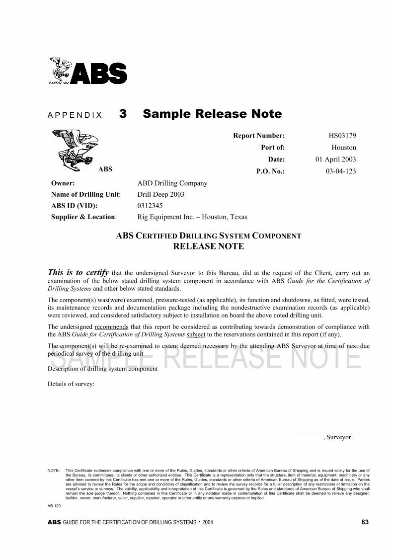
ABS GUIDE FOR THE CERTIFICATION OF DRILLING SYSTEMS . 2004 83
SAMPLE RELEASE NOTE
A P P E N D I X 3 Sample Release Note Report Number: HS03179
Port of: HoustonDate: 01 April 2003
ABS P.O. No.: 03-04-123Owner: ABD Drilling Company Name of Drilling Unit: Drill Deep 2003 ABS ID (VID): 0312345 Supplier & Location: Rig Equipment Inc. – Houston, Texas
ABS CERTIFIED DRILLING SYSTEM COMPONENT RELEASE NOTE
This is to certify that the undersigned Surveyor to this Bureau, did at the request of the Client, carry out an examination of the below stated drilling system component in accordance with ABS Guide for the Certification of Drilling Systems and other below stated standards.
The component(s) was(were) examined, pressure-tested (as applicable), its function and shutdowns, as fitted, were tested, its maintenance records and documentation package including the nondestructive examination records (as applicable) were reviewed, and considered satisfactory subject to installation on board the above noted drilling unit.
The undersigned recommends that this report be considered as contributing towards demonstration of compliance with the ABS Guide for Certification of Drilling Systems subject to the reservations contained in this report (if any).
The component(s) will be re-examined to extent deemed necessary by the attending ABS Surveyor at time of next due periodical survey of the drilling unit Description of drilling system component Details of survey:
________________________ , Surveyor NOTE: This Certificate evidences compliance with one or more of the Rules, Guides, standards or other criteria of American Bureau of Shipping and is issued solely for the use of
the Bureau, its committees, its clients or other authorized entities. This Certificate is a representation only that the structure, item of material, equipment, machinery or any other item covered by this Certificate has met one or more of the Rules, Guides, standards or other criteria of American Bureau of Shipping as of the date of issue. Parties are advised to review the Rules for the scope and conditions of classification and to review the survey records for a fuller description of any restrictions or limitation on the vessel’s service or surveys. The validity, applicability and interpretation of this Certificate is governed by the Rules and standards of American Bureau of Shipping who shall remain the sole judge thereof. Nothing contained in this Certificate or in any notation made in contemplation of this Certificate shall be deemed to relieve any designer, builder, owner, manufacturer, seller, supplier, repairer, operator or other entity or any warranty express or implied.
AB 120

This Page Intentionally Left Blank