Embed Size (px)
Citation preview
Foundations
LONDON DISTRICT SURVEYORS ASSOCIATION PUBLICATIONS
2017
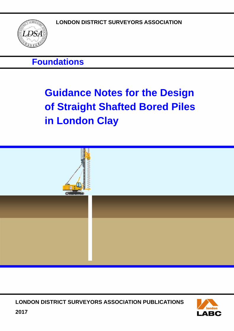
Guidance Notes for the Design of Straight Shafted Bored Piles in London Clay
LONDON DISTRICT SURVEYORS ASSOCIATION
- 1 -
Foreword This guidance note was first published in 1999 the purpose of which was to establish a common approach to the design of piles founded in London clay. The guide has been adopted by many designers over the past 18 years and has therefore become a valued document. The publication of this guidance note comes when the London District Surveyors Association [LDSA] celebrates its 30th Anniversary from formation. The 2009 version of this guidance note indicated that the next evolution of this document would be extended to be compatible with Eurocode 7. This revision incorporates guidance on how to apply Eurocode 7 to the design of straight shafted piles in London Clay. It has been written with reference to Eurocode 7 Parts 1 and 2 (BS EN 1997-1:2004+A1:2013 and BS EN 1997-2:2007) and the UK National Annexes to Eurocode 7 (NA+A1:2014 to BS EN 1997-1:2004+A1:2013 and NA to BS EN 1997-2:2007). It is envisaged that future evolutions of these guidance notes will omit the working stress approach in favour of the Eurocode 7 limit state approach. In common with the previous revision, these guidance notes set out a common approach to the design of piles in London Clay. They set out the parameters and design criteria that should, in normal circumstances, be acceptable to the checking authority when considering calculations and details submitted under the Building Regulations with adequate levels of site supervision performed by the designer/contractor. These notes do not preclude the use of other parameters and design criteria, but such an approach may require more detailed justification by the designer and greater consideration by the checking authority. These guidance notes are now published for the convenience of Engineers involved in the design of piled foundations in order that they may be aware of these criteria. These notes are not a "design manual" and designers must use their own professional judgement as to the suitability of the standards set out in these notes and should use more stringent criteria if they consider it appropriate. Anthony Oloyede, BSc (Hons) FRICS, C. Build E FCABE, MFPWS President, London District Surveyors' Association
October 2017

- 2 -
Acknowledgement The London District Surveyor’s Association is very pleased to acknowledge the input of Ove Arup & Partners Limited (Arup) working alongside members of the LDSA, in the production of this updated guidance note. The assistance of members of the Federation of Piling Specialists (FPS) is also acknowledged.
Authors
Dinesh Patel Arup
Stuart Pennington Arup
Reviewers
Paul Morrison Arup
Mark Pennington FPS
Stuart Norman FPS
Andrew Woods City of London
LDSA members
Mark Pundsack City of London
Siva Kumar London Borough of Hammersmith & Fulham
Manmohan Seyan London Borough of Camden

- 3 -
1. Purpose 1.1 The main purpose of the revision to the guide is:
To bring the use of Eurocode 7 limit state design (by calculation) within the scope of the guide, as an alternative to the existing working stress method.
To review the shaft adhesion factor ‘alpha’. To offer further general guidance and background information. To offer good practice notes for pile construction which reduce vulnerability to
underperformance of piles.
1.2 The approach is intended to be a prudent yet economical basis for design.
1.3 These Guidance Notes describe the general approach recommended for the design of straight-shafted rotary bored piles in London Clay, which if followed should satisfy the requirements of A1 of Schedule 1 of The Building Regulations 2010. Approval for pile designs not complying with this design approach will have to obtain the approval of the Local authority on a project specific basis, rather than being "deemed to satisfy".
- 4 -
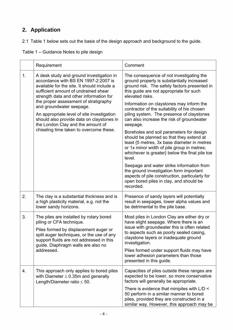
2. Application 2.1 Table 1 below sets out the basis of the design approach and background to the guide.
Table 1 – Guidance Notes to pile design
Requirement Comment
1. A desk study and ground investigation in accordance with BS EN 1997-2:2007 is available for the site. It should include a sufficient amount of undrained shear strength data and other information for the proper assessment of stratigraphy and groundwater seepage.
An appropriate level of site investigation should also provide data on claystones in the London Clay and the amount of chiseling time taken to overcome these.
The consequence of not investigating the ground properly is substantially increased ground risk. The safety factors presented in this guide are not appropriate for such elevated risks.
Information on claystones may inform the contractor of the suitability of his chosen piling system. The presence of claystones can also increase the risk of groundwater seepage.
Boreholes and soil parameters for design should be planned so that they extend at least {5 metres, 3x base diameter in metres or 1x minor width of pile group in metres; whichever is greater} below the final pile toe level.
Seepage and water strike information from the ground investigation form important aspects of pile construction, particularly for open bored piles in clay, and should be recorded.
2. The clay is a substantial thickness and is a high plasticity material, e.g. not the lower sandy horizons.
Presence of sandy layers will potentially result in seepages, lower alpha values and be detrimental to the pile base.
3. The piles are installed by rotary bored piling or CFA technique.
Piles formed by displacement auger or split auger techniques, or the use of any support fluids are not addressed in this guide. Diaphragm walls are also no addressed.
Most piles in London Clay are either dry or have slight seepage. Where there is an issue with groundwater this is often related to aspects such as poorly sealed casing, claystone layers or inadequate ground investigation.
Piles formed under support fluids may have lower adhesion parameters than those presented in this guide.
4. This approach only applies to bored piles with Diameter 0.35m and generally Length/Diameter ratio 50.
Capacities of piles outside these ranges are expected to be lower, so more conservative factors will generally be appropriate.
There is evidence that minipiles with L/D < 50 perform in a similar manner to bored piles, provided they are constructed in a similar way. However, this approach may be
- 5 -
invalid for different forms of minipile construction that allow the London Clay to be exposed to water.
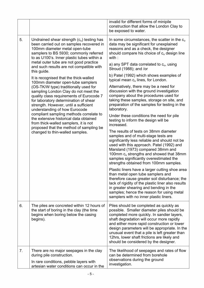
5. Undrained shear strength (cu) testing has been carried out on samples recovered in 100mm diameter metal open-tube samplers to BS 5930; commonly referred to as U100’s. Inner plastic tubes within a metal outer tube are not good practice and such results are not compatible with this guide.
It is recognised that the thick-walled 100mm diameter open-tube samplers (OS-TK/W type) traditionally used for sampling London Clay do not meet the quality class requirements of Eurocode 7 for laboratory determination of shear strength. However, until a sufficient understanding of how Eurocode compliant sampling methods correlate to the extensive historical data obtained from thick-walled samplers, it is not proposed that the method of sampling be changed to thin-walled samples.
In some circumstances, the scatter in the cu data may be significant for unexplained reasons and as a check, the designer should compare his choice of cu design line with :
a) any SPT data correlated to cu, using Stroud (1988); and /or
b) Patel (1992) which shows examples of typical mean cu lines, for London.
Alternatively, there may be a need for discussion with the ground investigation company about the procedures used for taking these samples, storage on site, and preparation of the samples for testing in the laboratory.
Under these conditions the need for pile testing to inform the design will be increased.
The results of tests on 38mm diameter samples and of multi-stage tests are significantly less reliable and should not be used with this approach. Patel (1992) and Marsland (1973) compared 38mm and 100mm cu strengths and showed that 38mm samples significantly overestimated the strengths obtained from 100mm samples.
Plastic liners have a larger cutting shoe area than metal open tube samplers and therefore cause greater soil disturbance; the lack of rigidity of the plastic liner also results in greater shearing and bending in the samples; hence the reason for using metal samplers with no inner plastic liners.
6. The piles are concreted within 12 hours of the start of boring in the clay (the time begins when boring below the casing begins).
Piles should be completed as quickly as possible. Smaller diameter piles should be completed more quickly. In sandier layers, shaft degradation will occur more rapidly and either more rapid construction or lower design parameters will be appropriate. In the unusual event that a pile is left greater than 12hrs, lower shaft frictions are likely and should be considered by the designer.
7. There are no major seepages in the clay during pile construction.
In rare conditions, pebble layers with artesian water conditions can occur in the
The likelihood of seepages and rates of flow can be determined from borehole observations during the ground investigation.

- 6 -
London Clay. Major seepages are defined as those that wet more that 20% of the pile shaft prior to concreting. Wetter shafts may need reduced design parameters, downgraded pile capacities, additional pile testing to investigate the impact of seepages, and/or a possible change to the construction method to prevent the shaft becoming excessively wet.
Artesian pressures can, in addition to wetting the shaft, have an effect on pile integrity, particularly the pile base.
8. The pile design is dictated by permanent vertical loads with no significant cyclical or variable component of loading.
Large magnitude cyclical loading can result in reduced design parameters for vertical loading. Cyclical horizontal loading can lead to “post-holing”, which may lead to the upper portion of the shaft length being discounted.
9. The basement excavation is not more than 5m.
Where basement excavation (i.e. new excavation) is deeper than 5m, additional analyses to those described in this guide will be necessary.
For example, (i) piles may have a lower capacity when assessed using an effective stress approach, and (ii) piles will be subjected to more significant tensile stresses from heaving ground.
10. The Works are monitored on a full-time basis by a knowledgeable and competent person independent of the operational piling crew.
This person should also be aware of the design basis and associated ground risks to the pile design; from discussions with the designer.
The observations should be independent of the piling foreman to ensure a proper check on the piling process.
In case of problems from unusual ground conditions or workmanship, the competent person is to clearly identify these issues and immediately inform the designer for review/ action.
11. The works and any testing are carried out in accordance with the ICE Specification for Piling and Embedded Retaining Walls (SPERW), 2016, 3rd edition.
12. The execution of the works (and construction monitoring) considers material quality and pile integrity.
A good desk study and ground investigation can sometimes highlight possible factors that may allow defects to occur during the pile construction e.g. voids in the fill.
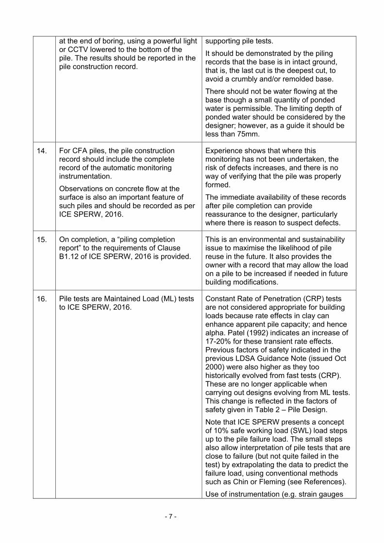
13. For rotary bored piles, an inspection of the base of the pile should be carried out
The base should be clear of cuttings and of similar quality to that observed in any
- 7 -
at the end of boring, using a powerful light or CCTV lowered to the bottom of the pile. The results should be reported in the pile construction record.
supporting pile tests.
It should be demonstrated by the piling records that the base is in intact ground, that is, the last cut is the deepest cut, to avoid a crumbly and/or remolded base.
There should not be water flowing at the base though a small quantity of ponded water is permissible. The limiting depth of ponded water should be considered by the designer; however, as a guide it should be less than 75mm.
14. For CFA piles, the pile construction record should include the complete record of the automatic monitoring instrumentation.
Observations on concrete flow at the surface is also an important feature of such piles and should be recorded as per ICE SPERW, 2016.
Experience shows that where this monitoring has not been undertaken, the risk of defects increases, and there is no way of verifying that the pile was properly formed.
The immediate availability of these records after pile completion can provide reassurance to the designer, particularly where there is reason to suspect defects.
15. On completion, a “piling completion report” to the requirements of Clause B1.12 of ICE SPERW, 2016 is provided.
This is an environmental and sustainability issue to maximise the likelihood of pile reuse in the future. It also provides the owner with a record that may allow the load on a pile to be increased if needed in future building modifications.
16. Pile tests are Maintained Load (ML) tests to ICE SPERW, 2016.
Constant Rate of Penetration (CRP) tests are not considered appropriate for building loads because rate effects in clay can enhance apparent pile capacity; and hence alpha. Patel (1992) indicates an increase of 17-20% for these transient rate effects. Previous factors of safety indicated in the previous LDSA Guidance Note (issued Oct 2000) were also higher as they too historically evolved from fast tests (CRP). These are no longer applicable when carrying out designs evolving from ML tests. This change is reflected in the factors of safety given in Table 2 – Pile Design.
Note that ICE SPERW presents a concept of 10% safe working load (SWL) load steps up to the pile failure load. The small steps also allow interpretation of pile tests that are close to failure (but not quite failed in the test) by extrapolating the data to predict the failure load, using conventional methods such as Chin or Fleming (see References).
Use of instrumentation (e.g. strain gauges
- 8 -
and fibre optics within test piles) provides significant insight into pile behavior and designers should consider specifying them.
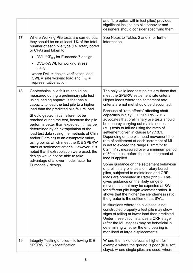
17. Where Working Pile tests are carried out, they should be on at least 1% of the total number of each pile type (i.e. rotary bored or CFA) and taken to:
DVL+½Frep for Eurocode 7 design
DVL+½SWL for working stress design
where DVL = design verification load, SWL = safe working load and Frep = representative action.
See Notes to Tables 2 and 3 for further information.
18. Geotechnical pile failure should be measured during a preliminary pile test using loading apparatus that has a capacity to load the test pile to a higher load than the predicted pile failure load.
Should geotechnical failure not be reached during the test, because the pile performs better than expected, it may be determined by an extrapolation of the load test data (using the methods of Chin and/or Fleming) to an asymptotic value, using points which meet the ICE SPERW rates of settlement criteria. However, it is noted that if extrapolation were used, the design would not be able to take advantage of a lower model factor for Eurocode 7 design.
The only valid load test points are those that meet the SPERW settlement rate criteria. Higher loads where the settlement rate criteria are not met should be discounted.
Because of “rate effects” affecting shaft capacities in clay, ICE SPERW, 2016 advocates that preliminary pile tests should be done by carrying out maintained load (ML) tests to failure using the rates of settlement given in clause B17.13.1. Depending on the pile head movement the rate of settlement at each increment of ML is not to exceed the range 0.1mm/hr to 0.2mm/hr, measured over a minimum period of 30minutes, before the next increment of load is applied.
Some guidance on the settlement behaviour of preliminary pile tests on rotary bored piles, subjected to maintained and CRP loads are presented in Patel (1992). This gives guidance on the likely range of movements that may be expected at SWL for different pile length /diameter ratios. It shows that the higher the slenderness ratio, the greater is the settlement at SWL.
In situations where the pile base is not constructed properly a test pile may show signs of failing at lower load than predicted. Under these circumstances a CRP stage (after the ML stages) may be beneficial in determining whether the end bearing is mobilised at large displacements.
19 Integrity Testing of piles – following ICE SPERW, 2016 specification.
Where the risk of defects is higher, for example where the ground is poor (fills/ soft clays); where single piles are used; where

- 9 -
the pile sizes are small; and where sites are congested, consideration should be given to testing 100% of the piles.
Integrity testing of secant pile walls may not be suitable as the signal is affected by the pile interlock.
The designer should confirm the applicability of the test method selected based on aspects such as, the pile diameter, pile length and ground conditions.
20 Pile designs using the Eurocode 7 design by calculation method shall satisfy all relevant requirements of Eurocode 7.
The other Eurocode 7 methods of determining pile resistance are not part of this guide.
It is not the intention of this guide to exhaustively present all requirements of Eurocode 7. The designer should refer to Eurocode 7 when using this method of design.
21 Concrete is placed by a vertical and centrally located delivery tube, and allowed to free-fall into the pile bore (though not by more than 10m through a reinforcement cage)
The use of a tremie pipe embedded in the concrete is a lower-energy placement method and results in less force being delivered to the perimeter of the bore. This potentially reduces alpha below the values presented in Tables 2 and 3.
22 When employing underpowered drilling plant and/or oversized cutting heads caution should be exercised in using the alpha values presented in Tables 2 and 3.
Underpowered drilling plant has the potential to create smoother pile bores thereby reducing the achievable alpha value.
Oversized cutting heads have the potential to create a smeared surface to the pile bore thereby reducing the achievable alpha value.
23 For piles specified by the Engineer and designed by the Contractor, there should be compatibility and continuity of design assumptions between the Engineer and Contractor.
- 10 -
3. Design method Two design methods (limit state and working stress) are presented below. Either method is acceptable but the two methods should not be mixed or used together. 3.1 Eurocode 7 limit state approach, design by calculation Ultimate limit state (ULS) verification The design vertical resistance (Rd) of a bored pile in London Clay is given by the following expressions:
(i) Rd = Rc;d = Rs;d + Rb;d for a compression pile = Rs;k / s + Rb;k / b
Rd = Rt;d = Rt;k / s;t + W for a tension pile where, Rc;d = design value of compression resistance Rs;d = design value of shaft resistance Rb;d = design value of base resistance Rt;d = design value of tension resistance Rs;k = characteristic value of shaft resistance Rb;k = characteristic value of base resistance Rt;k = characteristic value of tension resistance s = partial factor for shaft resistance b = partial factor for base resistance s;t = partial factor for tension resistance
W = buoyant weight based on an inferior (i.e. lower) characteristic weight density for concrete and a design water level
(ii) Rs;k = (d.L..cu;k) / R;d ….and similarly for Rt;k where, d = pile diameter (m) L = pile penetration in London Clay (m) = adhesion factor over shaft length R;d = model factor
cu;k = characteristic undrained shear strength over length L determined from unconsolidated undrained (UU) triaxial tests on 100mm diameter (OS-TK/W sampler) undisturbed samples (kN/m2)
- the average value of (.cu;k) over the length of the pile shaft should not exceed 110kN/m2 except where a higher limiting value is proven by a pile load test.
(iii) Rb;k = (¼.d2.Nc.cub;k) / R;d
where,
- 11 -
d = pile diameter Nc = bearing capacity factor = 9 for circular bearing piles in clay R;d = model factor cub;k = characteristic undrained shear strength at the pile base measured in
UU triaxial tests on 100mm diameter (OS-TK/W sampler) undisturbed samples.
The design vertical resistance (Rd) is sufficient if it equals or exceeds the design value of the effects of actions (Ed), that is, Ed ≤ Rd. For the ultimate limit state using Design Approach 1 Combination 2, the basic form of the equation for Ed with a characteristic permanent action (Gk) and one characteristic variable action (Qk) is: Ed = Gk + 1.3Qk. Serviceability limit state (SLS) verification Eurocode requires that vertical displacement (the design value of the effects of actions, Ed) under serviceability limit state conditions is assessed and then checked against the limiting design value of the relevant serviceability criterion (Cd), so that Ed ≤ Cd. The manner for controlling settlement (for a pile in compression) presented in the working stress approach below (i.e. Qw = Qs/1.2) is not part of Eurocode; however, a similar check should be made to ensure that piles are shaft controlled under serviceability limit state conditions. The basic form of the expression to be used where there is a characteristic permanent action accompanied by one characteristic variable action is: Rs;k / (Gk + Qk) ≥ 1.0 The requirement presented in the working stress approach below, to limit the pile capacity to 25% of the 28-day characteristic concrete cube strength is not contained with the Eurocode. For structural design of concrete piles reference should be made to Eurocode 2 (BS EN 1992) and BS EN 1536:2010+A1:2015. 3.2 Traditional working stress approach The ultimate vertical capacity Q of a bored pile in London Clay is given by the following expressions:
(i) Q = Qs + Qb for a compression pile Q = Qs + W for a tension pile where,
Qs = ultimate shaft capacity Qb = ultimate base capacity W = buoyant weight
(ii) Qs = d.L..cu where,
d = pile diameter (m) L = pile penetration in London Clay (m)
- 12 -
= adhesion factor over shaft length
cu = average undrained shear strength over length L determined from unconsolidated undrained (UU) triaxial tests on 100mm diameter (OS-TK/W sampler) undisturbed samples (kN/m2)
the average value of (.cu) over the length of the pile shaft should not exceed 110kN/m2 except where a higher limiting value is proven by a pile load test.
(iii) Qb =¼.d2.Nc.cub
where, d = pile diameter Nc = bearing capacity factor = 9 for circular bearing piles in clay cub = undrained shear strength at the pile base measured in UU triaxial tests on 100mm diameter (OS-TK/W sampler) undisturbed samples.
The working vertical capacity Qw of the pile is taken as the lower value from the following three expressions:
(iv) Qw = (Qs + Qb)/F
where, F = Factor of Safety
(v) Qw = Qs/1.2
(vi) Qw = 25% of the characteristic concrete cube strength of pile at 28 days calculated on the cross-sectional area of the pile (unless compression steel is included) (ref. cl. 7.4.4.3.1 BS 8004:1986)
- 13 -
4. Choice of undrained shear strength profile 4.1 Eurocode 7 limit state approach, design by calculation
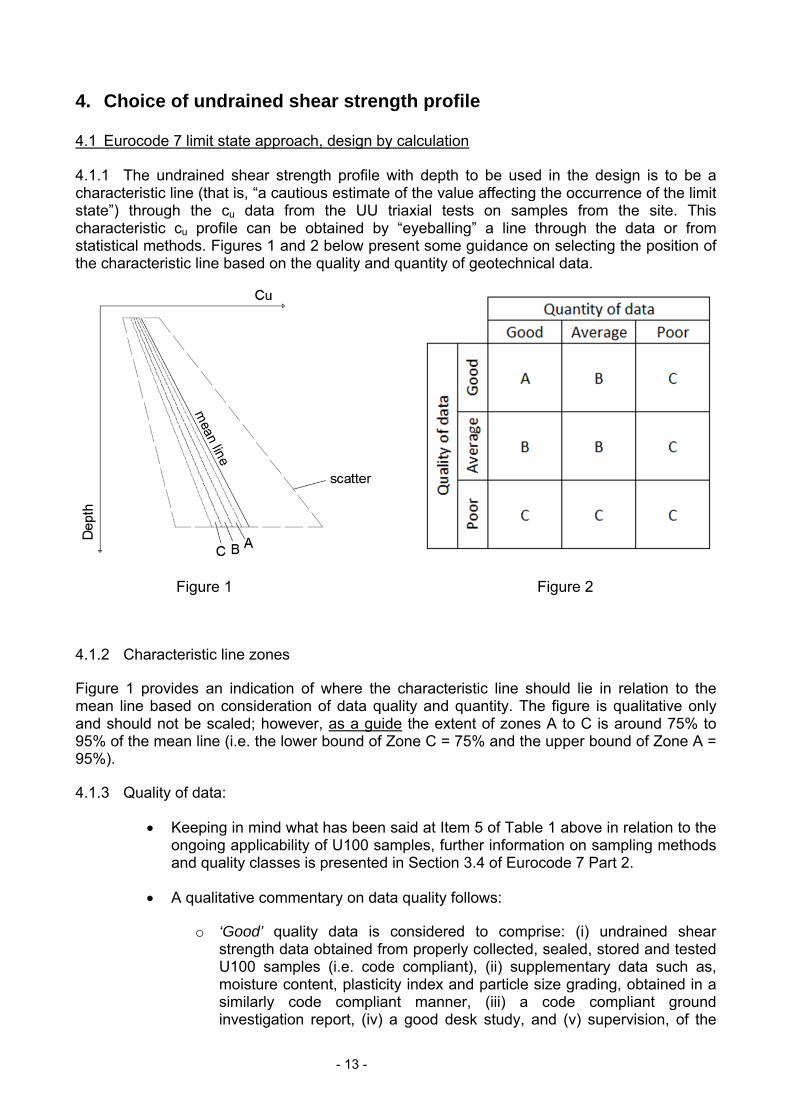
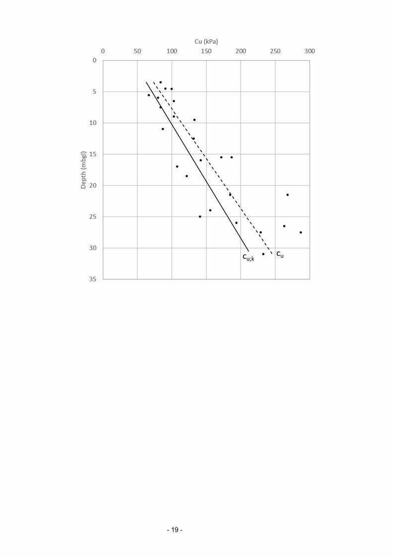
4.1.1 The undrained shear strength profile with depth to be used in the design is to be a characteristic line (that is, “a cautious estimate of the value affecting the occurrence of the limit state”) through the cu data from the UU triaxial tests on samples from the site. This characteristic cu profile can be obtained by “eyeballing” a line through the data or from statistical methods. Figures 1 and 2 below present some guidance on selecting the position of the characteristic line based on the quality and quantity of geotechnical data.
Figure 1 Figure 2
4.1.2 Characteristic line zones
Figure 1 provides an indication of where the characteristic line should lie in relation to the mean line based on consideration of data quality and quantity. The figure is qualitative only and should not be scaled; however, as a guide the extent of zones A to C is around 75% to 95% of the mean line (i.e. the lower bound of Zone C = 75% and the upper bound of Zone A = 95%).
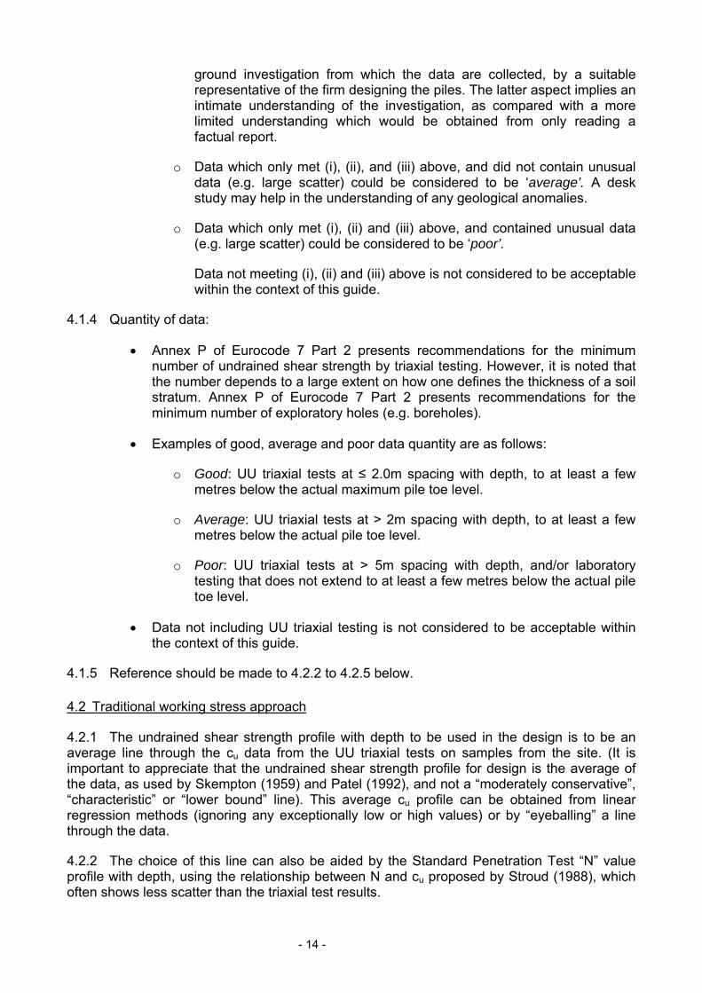
4.1.3 Quality of data:
Keeping in mind what has been said at Item 5 of Table 1 above in relation to the ongoing applicability of U100 samples, further information on sampling methods and quality classes is presented in Section 3.4 of Eurocode 7 Part 2.
A qualitative commentary on data quality follows:
o ‘Good’ quality data is considered to comprise: (i) undrained shear strength data obtained from properly collected, sealed, stored and tested U100 samples (i.e. code compliant), (ii) supplementary data such as, moisture content, plasticity index and particle size grading, obtained in a similarly code compliant manner, (iii) a code compliant ground investigation report, (iv) a good desk study, and (v) supervision, of the
- 14 -
ground investigation from which the data are collected, by a suitable representative of the firm designing the piles. The latter aspect implies an intimate understanding of the investigation, as compared with a more limited understanding which would be obtained from only reading a factual report.
o Data which only met (i), (ii), and (iii) above, and did not contain unusual data (e.g. large scatter) could be considered to be ‘average’. A desk study may help in the understanding of any geological anomalies.
o Data which only met (i), (ii) and (iii) above, and contained unusual data (e.g. large scatter) could be considered to be ‘poor’.
Data not meeting (i), (ii) and (iii) above is not considered to be acceptable within the context of this guide.
4.1.4 Quantity of data:
Annex P of Eurocode 7 Part 2 presents recommendations for the minimum number of undrained shear strength by triaxial testing. However, it is noted that the number depends to a large extent on how one defines the thickness of a soil stratum. Annex P of Eurocode 7 Part 2 presents recommendations for the minimum number of exploratory holes (e.g. boreholes).
Examples of good, average and poor data quantity are as follows:
o Good: UU triaxial tests at ≤ 2.0m spacing with depth, to at least a few metres below the actual maximum pile toe level.
o Average: UU triaxial tests at > 2m spacing with depth, to at least a few metres below the actual pile toe level.
o Poor: UU triaxial tests at > 5m spacing with depth, and/or laboratory testing that does not extend to at least a few metres below the actual pile toe level.
Data not including UU triaxial testing is not considered to be acceptable within the context of this guide.
4.1.5 Reference should be made to 4.2.2 to 4.2.5 below. 4.2 Traditional working stress approach
4.2.1 The undrained shear strength profile with depth to be used in the design is to be an average line through the cu data from the UU triaxial tests on samples from the site. (It is important to appreciate that the undrained shear strength profile for design is the average of the data, as used by Skempton (1959) and Patel (1992), and not a “moderately conservative”, “characteristic” or “lower bound” line). This average cu profile can be obtained from linear regression methods (ignoring any exceptionally low or high values) or by “eyeballing” a line through the data.
4.2.2 The choice of this line can also be aided by the Standard Penetration Test “N” value profile with depth, using the relationship between N and cu proposed by Stroud (1988), which often shows less scatter than the triaxial test results.

- 15 -
4.2.3 Patel (1992 – see Figure 2) shows typical average cu lines (based on 100mm triaxial tests) used in London and any design cu line used falling outside this range should be used with caution.
4.2.4 The designer should consider the need for pile testing and/or further site investigation, where appropriate.
4.2.5 Patel (1992 – see Figure 1) shows that undrained triaxial tests on 38mm samples taken from U100 tubes overpredict the cu. This guidance note does not apply to these tests.
- 16 -
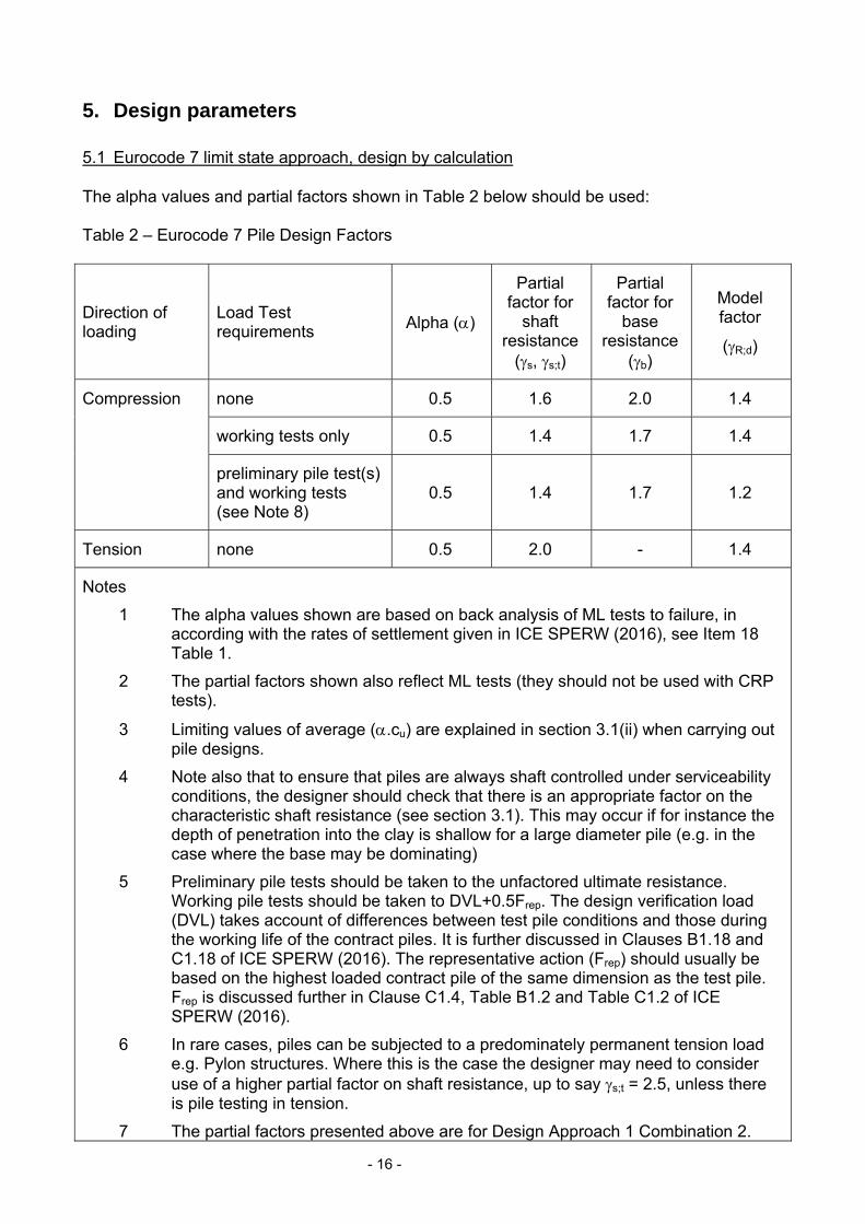
5. Design parameters 5.1 Eurocode 7 limit state approach, design by calculation The alpha values and partial factors shown in Table 2 below should be used: Table 2 – Eurocode 7 Pile Design Factors
Direction of loading
Load Test requirements Alpha ()
Partial factor for
shaft resistance
(s, s;t)
Partial factor for
base resistance
(b)
Model factor
(R;d)
Compression none 0.5 1.6 2.0 1.4
working tests only 0.5 1.4 1.7 1.4
preliminary pile test(s) and working tests (see Note 8)
0.5 1.4 1.7 1.2
Tension none 0.5 2.0 - 1.4
Notes
1 The alpha values shown are based on back analysis of ML tests to failure, in according with the rates of settlement given in ICE SPERW (2016), see Item 18 Table 1.
2 The partial factors shown also reflect ML tests (they should not be used with CRP tests).
3 Limiting values of average (.cu) are explained in section 3.1(ii) when carrying out pile designs.
4 Note also that to ensure that piles are always shaft controlled under serviceability conditions, the designer should check that there is an appropriate factor on the characteristic shaft resistance (see section 3.1). This may occur if for instance the depth of penetration into the clay is shallow for a large diameter pile (e.g. in the case where the base may be dominating)
5 Preliminary pile tests should be taken to the unfactored ultimate resistance. Working pile tests should be taken to DVL+0.5Frep. The design verification load (DVL) takes account of differences between test pile conditions and those during the working life of the contract piles. It is further discussed in Clauses B1.18 and C1.18 of ICE SPERW (2016). The representative action (Frep) should usually be based on the highest loaded contract pile of the same dimension as the test pile. Frep is discussed further in Clause C1.4, Table B1.2 and Table C1.2 of ICE SPERW (2016).
6 In rare cases, piles can be subjected to a predominately permanent tension load e.g. Pylon structures. Where this is the case the designer may need to consider use of a higher partial factor on shaft resistance, up to say s;t = 2.5, unless there is pile testing in tension.
7 The partial factors presented above are for Design Approach 1 Combination 2.
- 17 -
Combination 1 can typically be satisfied by observation rather than undertaking a calculation.
8 The requirement to undertake a preliminary and working pile testing is more onerous than the Eurocode (see Note ‘A’ to Tables A.NA.7 and A.NA.8 of the National Annex).
9 Additional tensions cases for working and preliminary pile tests have not been considered as there is little available data on ‘alpha’ in tension.
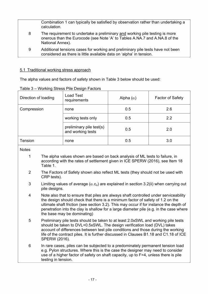
5.1 Traditional working stress approach The alpha values and factors of safety shown in Table 3 below should be used: Table 3 – Working Stress Pile Design Factors
Direction of loading Load Test requirements Alpha () Factor of Safety
Compression none 0.5 2.6
working tests only 0.5 2.2
preliminary pile test(s) and working tests
0.5 2.0
Tension none 0.5 3.0
Notes
1 The alpha values shown are based on back analysis of ML tests to failure, in according with the rates of settlement given in ICE SPERW (2016), see Item 18 Table 1.
2 The Factors of Safety shown also reflect ML tests (they should not be used with CRP tests).
3 Limiting values of average (.cu) are explained in section 3.2(ii) when carrying out pile designs.
4 Note also that to ensure that piles are always shaft controlled under serviceability the design should check that there is a minimum factor of safety of 1.2 on the ultimate shaft friction (see section 3.2). This may occur if for instance the depth of penetration into the clay is shallow for a large diameter pile (e.g. in the case where the base may be dominating)
5 Preliminary pile tests should be taken to at least 2.0xSWL and working pile tests should be taken to DVL+0.5xSWL. The design verification load (DVL) takes account of differences between test pile conditions and those during the working life of the contract piles. It is further discussed in Clauses B1.18 and C1.18 of ICE SPERW (2016).
6 In rare cases, piles can be subjected to a predominately permanent tension load e.g. Pylon structures. Where this is the case the designer may need to consider use of a higher factor of safety on shaft capacity, up to F=4, unless there is pile testing in tension.
- 18 -
6. Example calculations The following example calculations are provided to illustrate how a traditional working stress design compares to a Eurocode 7 limit state design for a common site. Problem to solve:
Calculate the pile length needed for the loads given. Parameters:
Pile diameter: 0.9m
Unfactored loads: D = 1000kN, L = 250kN
Characteristic actions: Gk = 1000kN, Qk = 250kN
Working pile tests: 1%, Preliminary pile tests: none.
Stratigraphy: Made ground 0 to 1 mbgl
Terrace gravel 2 to 3 mbgl London Clay 3 to 50 mbgl
Site investigation:
o Site investigation not supervised by the Engineer/Designer o Quantity of data judged as ‘good’ o Quality of data judged as ‘average’ o Characteristic line zone: B.
Undrained shear strength:
Average (by statistical best fit) = 70+6.3z Characteristic (by eye through Zone B) = 60+5.5z
where, z is depth below top of London Clay
- 19 -
- 20 -
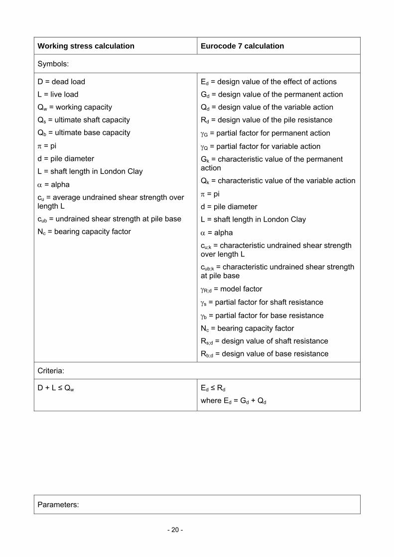
Working stress calculation Eurocode 7 calculation
Symbols:
D = dead load
L = live load
Qw = working capacity
Qs = ultimate shaft capacity
Qb = ultimate base capacity
= pi
d = pile diameter
L = shaft length in London Clay
= alpha
cu = average undrained shear strength over length L
cub = undrained shear strength at pile base
Nc = bearing capacity factor
Ed = design value of the effect of actions
Gd = design value of the permanent action
Qd = design value of the variable action
Rd = design value of the pile resistance
G = partial factor for permanent action
Q = partial factor for variable action
Gk = characteristic value of the permanent action
Qk = characteristic value of the variable action
= pi
d = pile diameter
L = shaft length in London Clay
= alpha
cu;k = characteristic undrained shear strength over length L
cub;k = characteristic undrained shear strength at pile base
R;d = model factor
s = partial factor for shaft resistance
b = partial factor for base resistance
Nc = bearing capacity factor
Rs;d = design value of shaft resistance
Rb;d = design value of base resistance
Criteria:
D + L ≤ Qw Ed ≤ Rd
where Ed = Gd + Qd
Parameters:

- 21 -
= 3.142
d = 0.9m
= 0.5
Average cu line = 70+6.3z
Nc = 9
F = 2.2 ..(working tests only)
= 3.142
d = 0.9m
= 0.5
Characteristic cu line = 60+5.5z
Nc = 9
G = 1.0, Q = 1.3 (ULS), 1.0 (SLS)
R;d = 1.4 ..(no preliminary tests)
s = 1.4 (ULS), 1.0 (SLS) ..(working tests only)
b = 1.7 ..(working tests only)
Equations:
Qs = d.L..cu
Qb =¼.d2.Nc.cub
Qw = min [ (Qs + Qb)/F , Qs/1.2 ]
Ed = G.Gk + Q.Qk
Rs;k = d.L..cu;k / R;d
Rs;d = Rs;k / s
Rb;d = ¼.d2.Nc.cub;k / R;d / b
Rd = Rs;d + Rb;d ….. ULS
Rs;k / (Gk + Qk) ≥ 1.0 …… SLS
Calculations:
D + L = 1000 + 250 = 1250
cu = 70+6.3(L/2) = 70+3.1L
cub = 70+6.3L
Qs = 3.142 x 0.9 x L x 0.5 x (70+3.1L)
Qb = 0.25 x 3.142 x 0.92 x 9 x (70+6.3L)
Qw = the lesser of (Qs + Qb) / 2.2 and Qs / 1.2
After reduction the equation for Qw becomes the lesser of 2.02L2+61.4L+182 and 3.71L2+82.5L
Taking Qw as 1250kN and solving for L yields 12.4m or a total pile length of 12.4+3=15.4m. In this example (Qs + Qb) / 2.2 dominates.
Ultimate limit state
Ed = 1 x 1000 + 1.3 x 250 = 1325
cu;k = 60+5.5(L/2) = 60+2.75L
cub;k = 60+5.5L
Rd = 3.142 x 0.9 x L x 0.5 x (60+2.75L) / 1.4 / 1.4 + 0.25 x 3.142 x 0.92 x 9 x (60+5.5L) / 1.4 / 1.7
After reduction the equation for Rd becomes:
1.98L2+56.5L+144
Taking Ed as 1325kN and solving for L yields 14.0m or a total pile length of 14+3=17.0m
Serviceability limit state
Gk + Qk = 1000 + 250 = 1250
Rs;k = 3.142 x 0.9 x L x 0.5 x (60+2.75L) / 1.4 = 1392
Therefore, Rs;k / (Gk + Qk) ≥ 1.0
- 22 -
7. General Commentary
7.1 Achieving a good alpha value in clay needs good site construction processes.
Alpha reduces where:
The bore is left open for longer.
Major seepages leading to “wet” shafts (20% threshold on wetted shaft area taken as an acceptable limit, provided this doesn’t occur disproportionately towards the higher strength lower section of the pile). It is important to concrete piles quickly to reduce risk of lower capacities.
Length / Diameter ratio increases as progressive failure of shaft can then occur.
There are excessive auger revolutions per unit penetration when CFA rigs are used.
Underpowered CFA rigs are used.
Alpha potentially reduces where:
Piles penetrate the sandier layers of the lower units of the London Clay.
The tremie is left embedded in the concrete during concrete placement instead of allowing the concrete to free-fall (in rotary bored piles).
Smearing / polishing of the pile bore surface is observed during pile inspection.
Seepages are high and water collects at base in significant quantities
7.2 For tension piles, a higher factor of safety is appropriate because of:
A possibly reduced stiffness of the structural element.
Creep.
The consequences of a progressive failure.
Lack of case data on pile tests in tension.
7.3 Where the information on a site does not comply with the requirements of this note, it is suggested that the factor of safety / partial factors are appropriately adjusted to reflect the higher risk level.
7.4 When a preliminary pile test is carried out, it may be possible to alter the design based on the actual result. This should generally be done by using the result to re-evaluate the undrained shear strength profile (either up or down). It is generally not prudent to take advantage of a good result that implies parameters that are better than those in these Guidance Notes. Some test results will always exceed the alpha results in this note; however, there is no guarantee that all other piles will be as good and some may be worse than the suggested parameter.
- 23 -
7.5 A typical straight shafted London Clay pile will have some 15% of the total capacity from the base component, with most from the shaft. A lower-bound alpha of 0.35 even with the intended parameters of F=2 and alpha = 0.5 would have a real F of 1.5 overall or 1.2 on shaft. At this level, it is still unlikely that a failure would occur and it is likely that this pile in this stratigraphy would still perform safely.
7.6 Where building columns are supported on single piles or small pile groups (less than 4), the building performance is more vulnerable to defects (or settlements) in individual piles compared with larger pile groups. The designer should carefully consider the risks associated with such piles, see Cameron and Chapman (2004).
7.7 For larger pile groups (number greater than 15); block failure of the whole pile group should also be considered in design.
7.8 It is good practice for the piling works to be supervised by competent and appropriately qualified engineer with relevant experience in the construction of London Clay piles.
7.9 For basement piles, geotechnical engineers should carry out an effective stress design and to compare this with the design approach described in this guide (a total stress design). Sometimes the capacity from the effective stress design may be the governing design. This also applies to piled basement walls embedded in London Clay and carrying vertical load.
- 24 -
References
Patel, D. (1992) Interpretation of pile tests in London Clay. Piling Europe Conference, ICE Thomas Telford publication, 1992.
Stroud, M. (1988) The Standard Penetration Test – its application and interpretation, ICE Geotechnical Conference on penetration testing in the UK.
Marsland, A. (1973) Insitu plate tests in lined and unlined boreholes in highly fissured London Clay at Wraysbury, BRE paper CP5/73.
ICE Specification for piling and embedded retaining walls (SPERW), 3rd Edition, 2016, Thomas Telford.
Fleming, W. (1992) A new method for single settlement prediction and analysis, Geotechnique Vol.42, Iss.3, pp.411-425.
Chin, F. (1970) Estimation of the ultimate load of piles from tests not carried to failure, Proc 2nd SE Asian Conf. Soil Engineering, Singapore, p81-92.
BS 8004:1986 Foundations, BSI
Cameron, G. and Chapman, T. (2004) Quality assurance of bored pile foundations, Ground Engineering, February, pp.35-40.
Skempton, A. (1959) Cast In-Situ Bored Piles in London Clay, Geotechnique Vol.9 Iss.4, pp.153-173.
BS 5930:2015 Code of practice for ground investigations, BSI.
BS EN 1997-1:2004+A1:2013, Eurocode 7 - Part 1, BSI.
BS EN 1997-2:2007, Eurocode 7 - Part 2, BSI.
NA+A1:2014 to BS EN 1997-1:2004+A1:2013, UK National Annex to Eurocode 7 - Part 1, BSI.
NA to BS EN 1997-2:2007, UK National Annex to Eurocode 7 - Part 2, BSI.
© LONDON DISTRICT SURVEYORS ASSOCIATION 2017
First Published 1999
2nd edition 2009
This edition 2017


![Skupniewicz Shafted Weapons[1]](https://img.pdfslide.us/doc/110x75/54ea58454a7959e7158b4f03/skupniewicz-shafted-weapons1.jpg)