Embed Size (px)
Citation preview

Issue 01- August 2008 page 1 of 18 © Heritage Railway Association 2008 The Heritage Railway Association, Limited by Guarantee, is Registered in England and Wales No. 2226245
Registered office: 2 Littlestone Road, New Romney, Kent, TN28 8PL
Ref No: HGR-B9001
Issue No: 01
Issue Date: August 2008
HERITAGE RAILWAY ASSOCIATION
GUIDANCE NOTE
TUBING OF LOCOMOTIVE BOILERS
Purpose This document describes good practice in relation to its subject to be carried out by Heritage Railways, Tramways and similar bodies to whom this document applies
Endorsement This document has been developed and fully endorsed by Her Majesty’s Railway Inspectorate, a directorate of the Office of Rail Regulation
Disclaimer The Heritage Railway Association has used its best endeavours to ensure that the content of this document is accurate, complete and suitable for its stated purpose. However it makes no warranties, express or implied, that compliance with the contents of this document shall be sufficient to ensure safe systems of work or operation. Accordingly the Heritage Railway Association will not be liable for its content or any subsequent use to which this document may be put.
Supply This document is published by the Heritage Railway Association
Copies are available electronically via our website www.heritagerailways.com

HGR-B9001-Is01____________________________ Tubing of Locomotive Boilers
Issue 01- August 2008 page 2 of 18 © Heritage Railway Association 2008 The Heritage Railway Association, Limited by Guarantee, is Registered in England and Wales No. 2226245
Registered office: 2 Littlestone Road, New Romney, Kent, TN28 8PL
Users of this Guidance Note should check the HRA website to ensure that they have the latest version.
Table of Contents 1. Introduction ........................................................................................................................................... 3 2. Dimensional Notation ........................................................................................................................... 3 3. Personal Protective Equipment ............................................................................................................ 3 4. Inspection ............................................................................................................................................. 3 5. Material Specifications.......................................................................................................................... 3 6. Removal of Tubes................................................................................................................................. 4 7. Cleaning of Tube Holes ........................................................................................................................ 5 8. Reaming of Tube Plate Holes............................................................................................................... 5 9. Screwed Tube Plate Bushes, Plugs and Ferrules................................................................................ 6 10. Tube Plate Liners.................................................................................................................................. 7 11. Tube Plates........................................................................................................................................... 7 12. Preparing for Tube Installation ............................................................................................................. 7 13. Flue Tubes............................................................................................................................................ 8 14. Tube Expanding.................................................................................................................................... 9 15. Beading............................................................................................................................................... 13 16. Seal Welding of Tubes ....................................................................................................................... 15 17. Welding procedure.............................................................................................................................. 16 18. Leaks .................................................................................................................................................. 16 19. Testing ................................................................................................................................................ 17 20. Record Keeping.................................................................................................................................. 17 21. Appendices ......................................................................................................................................... 17

HGR-B9001-Is01____________________________ Tubing of Locomotive Boilers
Issue 01- August 2008 page 3 of 18 © Heritage Railway Association 2008 The Heritage Railway Association, Limited by Guarantee, is Registered in England and Wales No. 2226245
Registered office: 2 Littlestone Road, New Romney, Kent, TN28 8PL
1. Introduction This Guidance Note is one of a series dealing with Locomotive Boilers that were produced by the 2006-8 meetings on “Steam Locomotive Boiler Codes of Practice”.
Railway locomotive boilers are designed to create, store and distribute steam at high pressure. The working life of such a boiler can be considerably shortened if due care is not taken at all stages of inspection, repair, running maintenance and day-to-day running.
In the past there have been a series of accidents and explosions due to work being undertaken without having due regard to the inherent risks involved. It is with that in mind that H.M.R.I. and H.R.A. set up the series of meetings of boiler practitioners to discuss the issues; distil good practice and codify it into this series of Guidance Notes.
This guidance is written for the assistance of people competent to perform these tasks. In places the terminology used may be specific to such practitioners.
This guidance will also be useful to those in a supervisory or more general role, however no work should be undertaken unless the people concerned are deemed competent to do so.
2. Dimensional Notation The original information frequently comes from documents that are in the imperial system only. Metric equivalents have been added where appropriate.
3. Personal Protective Equipment Before undertaking any works a risk assessment must be conducted.
Protective equipment is to be supplied and used at work wherever there are risks to health and safety that cannot be adequately controlled in other ways.
The equipment must be
• In accordance with the latest Personal Protective Equipment regulations. • Properly assessed before use to ensure it is suitable. • Maintained and stored properly • Provided with instructions on how to use it safely • Used correctly by those undertaking the work.
4. Inspection In the event of finding the tubes are suspect seek guidance from the boiler Competent Person before proceeding with any replacement.
5. Material Specifications. No boiler tubes should be replaced without prior approval of the Competent Person. All tubes obtained as replacements should be to British Standard Specification, BS EN 10216-1: 2002 (Seamless steel tubes for pressure purposes), BS EN 10217-1:2002 (welded steel tubes for pressure purposes), or an equivalent standard; see table below -
Detail Material Tensile Strength
Tons / sq “
BR Specification
Number
Equivalent
Grade
Boiler Tubes
and
Flue Tubes
Steel 20-28 123 or 122
BS 3602-320
BS 3059 PT1 320
HFS/CFS or ERW
Boiler Tubes Copper 14.5 min 317a BS 2871 PT3 C107-PA3

HGR-B9001-Is01____________________________ Tubing of Locomotive Boilers
Issue 01- August 2008 page 4 of 18 © Heritage Railway Association 2008 The Heritage Railway Association, Limited by Guarantee, is Registered in England and Wales No. 2226245
Registered office: 2 Littlestone Road, New Romney, Kent, TN28 8PL
All tubes must be perfectly sound, well finished, free from surface defects and rust, and the ends must be faced clean and square.
The tubes must be normalised before fitting.
The responsible person should retain the relevant material and test certificates for such tubes for as long as the tubes are in use.
6. Removal of Tubes There are two distinct methods of tube removal, with variations depending on the tools and skills available.
(1) One method involves loosening the tubes from both tube plates and removing each tube through its own hole in the front tube plate.
(2) In the other procedure, tubes are cut at each end and allowed to fall into the boiler barrel, with the tubes and cut ends removed later.
The first method can substantially be carried out with hand tools if shop facilities and power tools are not available, although the use of power tools will speed up the process and require less physical exertion. Removing the tubes through their own holes is also particularly advantageous if only a small number of tubes are to be removed – such as when replacing a group of thin or leaking tubes as a maintenance procedure or when removing two or more sample tubes from near the boiler bottom for examination to help determine general tube condition.
Work begins in the firebox where the bead (formed by riveting the end of the tube over so it bears against the plate) is removed from the tube end by using either a hand chisel, oxy-acetylene cutting torch or special chisel in a small pneumatic hammer. A tube drift is then inserted into the tube and the tube driven forward, loosening its grip where it has been rolled into both tube plates. Once loosened, the tube is easily removed unless heavily coated with scale, in which case it may be slid back and forth to knock off the scale. It is easier to drive the tube out if the smokebox end of the tube is first slit along its length for several inches using a square-ended “ripping” chisel, allowing the tube to collapse slightly. An alternative is to slit both ends of the tubes in two or more places and fully collapse the ends with chisels, then insert a long bar into the tube at the smokebox end and use it to draw the tube out far enough to be grasped by hand.
The second method involves cutting each tube at both tube plates using either a oxy-acetylene cutting torch or an internal tube cutter driven by a powerful pneumatic motor. If the cutting torch is used, tubes should be cut far enough back to avoid accidental damage to the plate.
Cut tubes are removed through a specially enlarged tube hole in the front tube plate (the “king hole”, located near the bottom of the centre column of tubes), or through suitable boiler openings such as a large superheater flue holes. The remaining tube ends in both tube plates are then removed by collapsing them with chisels and knocking them out of their holes. Collapsing can be aided by slitting the tube ends with a oxy-acetylene torch (using a small cutting tip), or cutting partially through with an electric saw or hacksaw. Another method is to heat the end of the tube that is still in the plate; then bend it away from the tube hole by striking with a chisel. The tube end may then be drawn clear through with little risk of damaging the hole.
A few cautions and helpful hints for tube removal should be mentioned.
(1) Extreme care must be exercised when using a cutting torch in case the flame nicks or gouges the seating surface of the tube hole. Because tube material is thin, only a small oxy-acetylene torch equipped with a tip designed for this type of work should be used in order to reduce the chance of accidental damage. The operator must be skilled – this is not a job for the inexperienced. Careful work at this time will reduce the amount of time and effort needed to repair damaged tube plate holes later.
(2) If using an electric saw or hacksaw, be careful that the saw does not cut into the tube plate – the same precautions given for using the oxy-acetylene cutting torch apply here.
(3) If tubes removed through the king hole, three or four small U-shaped shims or clips made from thin steel or brass should be placed around the inside of the hole to serve as wear plates. The abrasion wear produced by removing 200-300 tubes through the hole can wear the hole so out of round that it will have to be repaired by welding.

HGR-B9001-Is01____________________________ Tubing of Locomotive Boilers
Issue 01- August 2008 page 5 of 18 © Heritage Railway Association 2008 The Heritage Railway Association, Limited by Guarantee, is Registered in England and Wales No. 2226245
Registered office: 2 Littlestone Road, New Romney, Kent, TN28 8PL
(4) Avoid cutting too many tubes off at one end without cutting them free at the opposite end, as the hanging weight may strain the tube plates and cause cracks. This is especially true when cutting off the heavy superheater flues.
It’s a little more difficult to remove tubes when the firebox end beads have been seal welded to the tube plate, because either the bead or the weld (or both) must be cut through to permit tube removal.
Three methods of weld and bead removal may be used:
1) Grinding through the tube bead using a small disk or die grinder
2) Chipping off the weld and bead with a special angled chisel used in a pneumatic hammer
3) Cutting off the weld and bead with a oxy-acetylene cutting torch. The last two processes require considerable skill to remove enough of the weld and bead so the tube can be removed while at the same time avoiding damage to the rear tube plate by either undercutting with the chisel or nicking with the torch. Once the weld and bead have been removed the procedure is the same as for non-welded tubes.
Superheater flue removal presents additional problems of its own. Flues are made of thicker, less workable material than are tubes (making collapsing difficult), and their greater weight creates handling problems. Often these flues are removed through their own holes in the front tube plate, but this may be difficult if heavy scale has built up on them. It may be necessary to hammer off such scale prior to removal or to sacrifice the flues and cut them into pieces small enough to be passed through the steam dome.
7. Cleaning of Tube Holes The front and rear tube plate condition should be checked, possibly revealing cracks, cuts and gouges around tube holes not readily apparent beforehand. Also check for damage caused by tube removal, such as chisel or torch nicks not only on the faces of the plates but also on the surfaces of the holes themselves. Carefully grind the fire side of the tube plate (especially if tubes have been welded to the rear tube plate), removing as little material as possible in order to provide a fresh, smooth surface against which the tubes can be beaded. Grinding will reveal a narrow band or ridge around each tube hole, an indication that the tube plate is thicker where the metal has been forced outwards by the previous expanding process and where it has been protected from fire by the bead. It’s not necessary to remove these bands by grinding them down to the same thickness as the rest of the plate.
The tube holes will require cleaning and polishing, best done with a high speed fine wire, flap or sanding wheel. It can also be done with half-round files or by carefully manipulating a pneumatic or electric die-grinder with a 25 to 38mm (1″to 1½″) round grinding tool, but be careful not to introduce out-of-roundness or enlarge the hole excessively. The edges of each hole should be rounded slightly 1.6mm (1/16”) radius is suggested) on both faces to prevent the tube from being cut when it is expanded and beaded. This job is best done using a large diameter 45° grinding stone in a high speed grinder.
Nicks, gouges or cracks on the tube plates or in the tube holes will require attention unless they are very minor. (See section on Reaming of Tube Plate holes).
8. Reaming of Tube Plate Holes Any holes for small tubes which are elongated or otherwise out of round by (0.8mm) 1/32″ or more must be dealt with in the following manner:
For Copper tube plate.
Ream out to take a new tube. Alternatively after reaming an annealed copper liner can be fitted to bring the tube hole back to the original size. (Refer to section on Tube Plate Liners)
Expanding of holes for this purpose is prohibited.
For Steel tube plates.
Ream out to take a new tube. Holes may be built up by welding then either filed, reamed or bored to the correct size; subject to the agreement of the Competent Person and suitable NDT. Only welders properly qualified and certificated for this type of welding can undertake the task.

HGR-B9001-Is01____________________________ Tubing of Locomotive Boilers
Issue 01- August 2008 page 6 of 18 © Heritage Railway Association 2008 The Heritage Railway Association, Limited by Guarantee, is Registered in England and Wales No. 2226245
Registered office: 2 Littlestone Road, New Romney, Kent, TN28 8PL
9. Screwed Tube Plate Bushes, Plugs and Ferrules Whilst a repair by copper welding is preferred, fractured tube plate bridges maybe repaired by fitting screwed copper bushes which must be screwed in tightly and; where feasible; riveted over on both sides of the tube plate.
The bush is to be made by drilling and opening out one of the standard copper plugs as shown in diagram below.
If circumstances warrant it then the fitting of a maximum of four plugs in any one tube plate is permissible provided no two of these four plugs are adjacent to each other; however plugged and bushed holes may alternate.
The plugs to be used, copper for the firebox tube plate and steel for the smoke box tube plate are shown in the diagram below.
The use of ferrules to protect tubes is not permitted other than where originally specified from new or a design change has been approved by the insurer.
Ferrules must not be used as a repair for tubes that are worn thin or leaking to an extent that they cannot be kept tight after expansion. The purpose of the ferrule is to protect the tube end not to reinforce it.
Threads to be Whitworth form normal to the angle of taper.
Dimension ‘X’ to vary from 1 7/16” to 2 9/16” in 1/16” increments
Plugs for Tubeplates

HGR-B9001-Is01____________________________ Tubing of Locomotive Boilers
Issue 01- August 2008 page 7 of 18 © Heritage Railway Association 2008 The Heritage Railway Association, Limited by Guarantee, is Registered in England and Wales No. 2226245
Registered office: 2 Littlestone Road, New Romney, Kent, TN28 8PL
10. Tube Plate Liners In order to use standard tubes in tube plate holes which have been reamed out, annealed copper liners may be used in accordance with the following table:
Where it is considered a possibility to fit liners, it should be established that there is sufficient material to support the tubes. This work should not be undertaken without the prior consent of the competent person. In no circumstances should the thickness of a liner exceed 3.2mm (10SWG).
The liners must be lightly driven in flush with the fireside of the tube plate and then expanded in position. Standard five roller expanders must be used for this purpose.
11. Tube Plates Bowed tube plates in a poor condition must be replaced, but if serviceable, must be levelled.
12. Preparing for Tube Installation Be certain that all boiler repairs which can not be performed after the tubes are in have been completed.
Examine the insides of both tube plates for any undiscovered cracks or nicked tube holes, and make sure the tube holes are clean.
The ends of old tubes or tubes that have been swaged down will require normalising (heating their ends to bright cherry red (840 - 870 C ) and cooling them slowly) to soften the material - not only to ease rolling and beading, but also to prevent cracking during the installation process. A regulated gas oven is the best normalising tool, but a forge or heating torch will also work if care is taken to prevent burning the tubes, which results in heavy slag build-up, pitting and possible brittleness. The tube ends are usually cooled by plunging them into a bed of lime, which not only insulates, but also helps to minimize oxidation (scale). It’s not necessary to normalise the ends of new tubes, if they are delivered in a normalised state. If you have difficulty rolling new tubes, or if cracking occurs during rolling or beading, reject the tubes and contact the tube supplier for an explanation.
Nominal inside diameter of liner. Inches
Nominal outside diameter of liner. Inches
Nominal thickness
S.W.G. mm
For Tubes 1.1/2 -38.1mm 1.9/16 - 39.68mm 21 0.8
1.1/2”(38.1mm) 1.1/2 -38.1mm 1.19/32 -40.48mm 18 1.2
Diameter At End 1.1/2 -38.1mm 1.21/32 -42.06mm 14 2.0
For Tubes 1.5/8 -41.2mm 1.11/16 -42.86mm 21 0.8
1.5/8”(41.2mm) 1.5/8 -41.2mm 1.23/32 -43.65mm 18 1.2
diameter 1.5/8 -41.2mm 1.3/4 -44.45mm 16 1.6
At end 1.5/8 -41.2mm 1.25/32 -45.24mm 14 2.0
For tubes 1.3/4 -44.4mm 1.13/16 -46.03mm 21 0.8
1.3/4”(44.4mm) 1.3/4 -44.4mm 1.27/32 -46.83mm 18 1.2
Diameter At End 1.3/4 -44.4mm 1.7/8 -47.62mm 16 1.6
1.3/4 -44.4mm 1.29/32 -48.42mm 14 2.0
1.3/4 -44.4mm 1.15/16 -49.21mm 13 2.3
1.3/4 -44.4mm 2 -50.80mm 10 3.2
For tubes 2”(50.8mm) Diameter at end
2 -50.8mm 2.1/8 -53.97mm 16 1.6
HGR-B9001-Is01____________________________ Tubing of Locomotive Boilers
Issue 01- August 2008 page 8 of 18 © Heritage Railway Association 2008 The Heritage Railway Association, Limited by Guarantee, is Registered in England and Wales No. 2226245
Registered office: 2 Littlestone Road, New Romney, Kent, TN28 8PL
The tube ends must be free of any burrs left over from cutting, and should be lightly polished both inside and out for a length of 2”(50mm) to 3”(75mm) on both ends to remove mill scale or scale resulting from normalising.
After being cut to length, cleaned and swaged (if necessary), the tubes are ready to be placed into the boiler. Wipe the tubes just before inserting to remove dirt, loose scale, and any remaining oil or rust preventative; then inspect the tubes a final time, rejecting those which are dented, deeply scratched or gouged, or have damaged ends.
13. Flue Tubes Procedure for new screwed superheater flue tubes and tube plates
Pilot holes to be drilled in tube plate for tube holes. Tube holes to be opened out and a radius machined on the fireside of each hole, and finally tapped to suit the screwed end of the superheater flue tube.
Tube ends are to be screwed .007″(0.19mm) to .015″(0.38mm) below the nominal diameter, and at the same setting the bore must be cleaned out exactly concentric for a depth of 3¼″(82mm) from the end of the flue tube. From that point inwards the cut must be run into the original rough bore of the tube without any abrupt change in section. It is permissible to fabricate flue tubes by welding a separate swaged end onto a plain tube.
Only welders properly qualified and certificated for this type of welding can undertake the task.
The tube ends must be strictly concentric and in accordance with the appropriate drawing in all respects.
The threads in the copper tube plate must be cleaned out with a short tap revolved from the steel tube plate end by a long adaptor, the adaptor being guided by a bush put in the corresponding smoke box tube plate hole.
The tube plate on the water side must be lightly faced when necessary and coned 90 degrees to a depth of approximately 1/8” (3.18mm), the cutter being mounted on a mandrel screwed tightly into the copper plate.
At the firebox end on a screwed flue tube the wall thickness below the threaded portion of the tube at the point of expansion must be 3/16”(4.76mm) minimum, ¼″ (6.35mm) maximum.
Tubes may be screwed in using the standard tool, see sketch below, or if they have been ordered over length they may be screwed into place using the waste end and then cut to length in situ. Care must be taken to ensure that the end is clean and square before expansion.
Tool for inserting flue tubes

HGR-B9001-Is01____________________________ Tubing of Locomotive Boilers
Issue 01- August 2008 page 9 of 18 © Heritage Railway Association 2008 The Heritage Railway Association, Limited by Guarantee, is Registered in England and Wales No. 2226245
Registered office: 2 Littlestone Road, New Romney, Kent, TN28 8PL
14. Tube Expanding The type of expander used will be determined by the origin of the boiler.
Typically the Eastern and Southern regions used fireside expansion and the Western region and London Midland Region used waterside expansion. Modern industrial practice is to use parallel internal expansion.
An over-scale sketch of the effects of the two forms of expander is given above:
To re-expand tubes with an expander having a different direction of expansion to that previously employed will cause severe distortion and is therefore prohibited.

HGR-B9001-Is01____________________________ Tubing of Locomotive Boilers
Issue 01- August 2008 page 10 of 18 © Heritage Railway Association 2008 The Heritage Railway Association, Limited by Guarantee, is Registered in England and Wales No. 2226245
Registered office: 2 Littlestone Road, New Romney, Kent, TN28 8PL
Tube expansion begins in the firebox. 3 roller expanders should not be used in copper tubeplates due to the potential for deformation. Current practice favours the 5 roller expander as in drawing below
5 roller expander for Copper Tube 1 ¼” to 3 ¼”
6 roller expander for Steel Tubes
Expanders for small tubes
Each tube must project from the tube plate a required, pre-determined amount, usually between 3/16” (4.76mm) to 5/16” (7.93mm). (As the tubes are driven into position, keep a small plate metal gauge handy). The projection of the tube at both the firebox and smokebox ends must be checked to verify correct tube length. A little excess length is allowed in the smokebox, but short tubes should be rejected. The roller expander tends to pull the tube into the firebox as well as rotate it, so the tube must be anchored to the front tube plate. A good method is to grasp the projecting portion of the tube at the smokebox end with two pair of locking pliers, so that the lips of the pliers rest against the tube plate when the tube is in its proper position (as gauged in the firebox); the pliers also prevent the tube from spinning.
The expander should be lubricated, but be careful not to get oil between the tube and hole, which can cause a hydraulic lock preventing the tube from sealing properly. Use water-soluble oil so that the expander can be washed periodically. Compressed air may be used to blow dirt from the interior of the tube and from between the tube and its hole.
To avoid distortion of the tube plates, it is advisable to follow some systematic method in the fitting of the flues.
The sequence in which tubes are to be expanded will be laid down and should be adhered to; however, if the original order drawings are no longer available one the following methods may be adopted:
Method 1.
Finish a vertical central row, followed by a horizontal central row. Then finish each quadrant, successively working from the outside towards the centre.
Method 2.
Start expanding at the outside rows and work inward in a spiral manner to finish in the centre of the tube plate.

HGR-B9001-Is01____________________________ Tubing of Locomotive Boilers
Issue 01- August 2008 page 11 of 18 © Heritage Railway Association 2008 The Heritage Railway Association, Limited by Guarantee, is Registered in England and Wales No. 2226245
Registered office: 2 Littlestone Road, New Romney, Kent, TN28 8PL
Method 3.
The outer and bottom tubes are expanded first gradually working inwards and upward working towards the centre of the tube plate; the object being to distribute the compressing action of the expander as evenly as possible over the entire plate without distorting the tube plate.
The expander should be fully inserted into the tube. Expanders with thrust collars have a “bridge” which extends past the outside of the tube, and which must rest securely against the tube plate. An example is shown in drawing to the right:
Adaptor for small tube expanders
Be sure to select the tapered mandrel that will fully engage the rollers at the start. The mandrel may be turned by hand when necessary, but is generally driven by either pneumatic or electric “roll motors”. Using these motors in the confines of either the firebox or smokebox is hazardous because the high torque developed can easily cause the operation to lose control of the machine. Whenever possible brace the motor against the side or crown plate, or upon a bar inserted into a convenient tube, and hold onto the motor’s trigger in such a way as to avoid pinning the controlling hand in the event of a problem.
Once the mandrel has been placed in the expander and the motor connected and switched on, watch the action of the rollers against the tube wall as stretching begins. Most rollers are designed to self-feed the tapered mandrel, making it unnecessary to push it into the expander. As the mandrel is fed the tube will slowly grow in diameter and fill the hole. The rippling action of the tube will slowly diminish and then stop, accompanied by a slight straining of the motor, both indications that the tube has tightened in its hole.
Experience is necessary to determine if rolling should be continued beyond this degree of tightness. Sometimes a standard such as “one-half turn more” or “one turn more” is applied; alternatively the degree of expansion can be calculated as follows:

HGR-B9001-Is01____________________________ Tubing of Locomotive Boilers
Issue 01- August 2008 page 12 of 18 © Heritage Railway Association 2008 The Heritage Railway Association, Limited by Guarantee, is Registered in England and Wales No. 2226245
Registered office: 2 Littlestone Road, New Romney, Kent, TN28 8PL
Step A - Measure Tube Plate Hole
Step B - Measure Tube OD
Step C - Calculate Clearance (A–B)
Step D – Measure Tube ID
Step E – Calculate Total Wall Thickness (B–D)
Step F – Calculate 7% Wall Reduction (.07 × E)
Step G – Calculate Finished Rolled Tube ID (C+D+F)
For steel tubes the tube wall should be reduced by approximately 7% to 8% for optimum tube joints. When rolling copper, consider approximately 8% to10% wall reduction to produce a proper tube joint.
Considering the variations which occur in such items as tube wall thickness and diameter of tube hole, the work involved in measuring and re measuring each joint would make cost excessive.
Once the tube is tight, reverse the direction of the motor and pull the mandrel back while turning, releasing it from the rollers. If the motor will not reverse, remove the mandrel by turning it with a spanner.
When the firebox end is finished, proceed to the other end. Begin again at the centre to brace the plate. Be careful of the pulling action on the first tubes, because the tube plates may be pulled closer together at the centre, becoming dish-shaped. An expander without a thrust collar will help reduce this pulling tendency.
Superheater flues require larger rollers, and may demand heavier motors. It’s safer to locate heavier motors in the more spacious smokebox or on temporary platforms in front of the boiler. Many large expanders have drive bosses or connections at both ends of the tapered mandrel; when rolling at the rear tube plate; these connect the roller to the motor via a drive shaft slid through the flue.
Further consideration will show that regardless of the variation in clearance between the outside diameter of the tube and the tube hole, the work done in expanding the tube up to the inside diameter of the hole is relatively small compared with the work in actually reducing the wall thickness. Hence the degree of expansion can be controlled by actually measuring the amount of work necessary to give the required amount of wall thinning (which is, in fact, directly related to the torque exerted by the mandrel itself for any specific size of tube joint). Once the initial joint is actually measured and related to the torque on the mandrel, then the expansion of the other joints to the same torque reading give consistent results in line with that of the first expansion.
Keep in mind that the desired result is to seal the tubes while producing the least amount of stress in the tube plate. A tube which has been expanded slightly less than fully has a much better bond than a tube which has been stressed by overexpansion. It is better to under-roll than over-roll.

HGR-B9001-Is01____________________________ Tubing of Locomotive Boilers
Issue 01- August 2008 page 13 of 18 © Heritage Railway Association 2008 The Heritage Railway Association, Limited by Guarantee, is Registered in England and Wales No. 2226245
Registered office: 2 Littlestone Road, New Romney, Kent, TN28 8PL
15. Beading Once all tubes and flues are properly expanded, the ends are generally “beaded”, or riveted over against the tube plates. Beading begins in the firebox and should follow the same pattern used when expanding the tubes. The projecting end of each tube must first be “belled” or flared to about 45° (Min 35°).
If the expander used had extra “flaring” rollers, belling was done as the tubes were expanded. If not, use a commercial or home-made belling tool, driven by hand or pneumatic hammers. As shown in diagram below:
First operation, pneumatic tool for flaring tubes
The second operation is to bead over the edge of the flared tube, with a beading tool as shown below:
Beading tool for small tubes.

HGR-B9001-Is01____________________________ Tubing of Locomotive Boilers
Issue 01- August 2008 page 14 of 18 © Heritage Railway Association 2008 The Heritage Railway Association, Limited by Guarantee, is Registered in England and Wales No. 2226245
Registered office: 2 Littlestone Road, New Romney, Kent, TN28 8PL
Example of a beading tool for large flue tubes.
A beading or “thumb” tool can be used by hand or in a small to medium pneumatic hammer. Beading further seals or caulks the expanded joint; to produce the correct bead, hammer not only the end of the tube, but also the tube interior, bending the tube out against the hole in the plate. As shown.
Incorrect use of beading tool (left) Correct use of beading tool (right)
Start the air flow to the hammer slowly, and work the beading tool around the tube several times, gradually hammering the belled tip over and producing the finished bead. The bead must be formed without allowing the tip of the thumb to cut into the plate. As the tool wears, this tip will need to be ground back. Select tools with the proper radius for the tube thickness and allowed projection, and change tool size as necessary if the projecting length of tubes varies.
In the smokebox it isn’t always necessary to bead all the tubes. Generally a few rows of small tubes at the bottom are beaded for ease of cleaning; the tubes around the washout plugs are beaded to prevent damage from spanners and the small tubes in the area around the flues. Tubes which require beading but project too far from the plate should be trimmed off with a grinder or chisel before beading.
19
1.5
216 mm radius
22 mm octagon steel
Dia
19
Hand Tool To Chain Dot Lines

HGR-B9001-Is01____________________________ Tubing of Locomotive Boilers
Issue 01- August 2008 page 15 of 18 © Heritage Railway Association 2008 The Heritage Railway Association, Limited by Guarantee, is Registered in England and Wales No. 2226245
Registered office: 2 Littlestone Road, New Romney, Kent, TN28 8PL
16. Seal Welding of Tubes The method to be used should be agreed with the competent person prior to commencement. The tubes must be expanded before welding and lightly re-expanded after welding to help relieve stresses and prevent leakage caused by the welding heat.
In order to overcome problems caused by movement of the tubes and plates on steel fireboxes the firebox ends of the tubes can be welded. Before welding the tube plate must be clean, dry and free from oil.
The following diagrams illustrate welding alternatives. The second method eliminates beading. When deciding which method to use the following should be considered:
When using method one the seal weld may crack around the beading, although this can then be chipped out and the tube end re-welded to the tube plate.
The second method eliminates beading therefore the cracks around the beading; however, over a period cracks can develop from the weld into the tube lengthways causing tube failure.
Only welders properly qualified and certificated for this type of welding can undertake the task.
Method 1 Beaded tubes Method 2 Unbeaded tubes
Superheater flue tube
Small boiler tube
Sealingweld
weld to be finishedflush with bead
1/4" to 5/16" weld
Superheater flue tube
Small boiler tube
Sealingweld
3/16"
3/16"

HGR-B9001-Is01____________________________ Tubing of Locomotive Boilers
Issue 01- August 2008 page 16 of 18 © Heritage Railway Association 2008 The Heritage Railway Association, Limited by Guarantee, is Registered in England and Wales No. 2226245
Registered office: 2 Littlestone Road, New Romney, Kent, TN28 8PL
17. Welding procedure A welding procedure must be agreed with the Competent Person before commencement. Only welders properly qualified and certificated for this type of welding can undertake the task. The completed weld to be subjected to suitable NDT, unless agreed otherwise by the Competent Person.
A guide to the order of welding is given below.
ORDER OF WELDING
Start weld at “A” and work in the direction of “X” to “B”.
Then return to “A” and weld in the direction of “Y” to “B”, lapping over the end of the first weld.
18. Leaks In order to avoid tube leaks, it is essential to realise that the tube moves longitudinally in the tube plate as the temperature varies, and therefore correct manipulation of the fire-hole door and the deflector plate must be understood to prevent cold air from striking the tube plate. As there is movement between the tube and plate, the bearing surfaces of the tube and plate must be fairly smooth. A rough hole and tube surface would certainly be steam tight for a short time but relative movement soon wears the high spots and leakage occurs.
Continued expansion distorts the tube plate and thins the tube metal; in bad cases it is possible to imprison scale between the tube and the plate resulting in further leakages. It is sometimes beneficial in bad cases to expand the tubes surrounding the defective one first, thereby closing the metal onto the tube and reducing the amount of expansion for the one tube.
Rust should not be allowed to remain on the body of the tube or pitting is almost certain to result.
If leakages occurs around the tube ends remove the water from the boiler and re-bead the leaking tubes, this is normally sufficient and avoids the need for re-expanding.
A significant leak that does not readily seal may indicate a cracked tube or a crack developing in the tube plate ligament next to the tube.
If leakage occurs from the inside of the tube it is most likely due to corrosion or cracking. In this situation a thorough examination of ALL the tubes must be carried out and, with the approval of the responsible person, the defective tube(s) must be replaced.
The use of any type of tube plug or blank is not permitted unless specifically agreed with the Competent Person.

HGR-B9001-Is01____________________________ Tubing of Locomotive Boilers
Issue 01- August 2008 page 17 of 18 © Heritage Railway Association 2008 The Heritage Railway Association, Limited by Guarantee, is Registered in England and Wales No. 2226245
Registered office: 2 Littlestone Road, New Romney, Kent, TN28 8PL
19. Testing If the Boiler has been re-tubed; or the tubes have been re-expanded; either partially or fully and no other repair work has been undertaken. On completion of the tube replacement, expansion, beading and seal weld operations the boiler shall be subjected to a static cold water head pressure test with the boiler in a Water Wedged Condition (filled with no air space) for a duration no shorter than 12 hours.
The static head pressure test has a stipulated duration of 12 hours to ensure sufficient soak time for the test. Care should be taken to ensure that the water temperature within the boiler is maintained above 7 degrees Celsius at all times to avoid the possibility of Cold Brittle Fracture. (BS2790 Section 6 Issue 3)
Under certain circumstances hydraulic testing may supplement the static cold water head pressure test if directed by the Competent Person
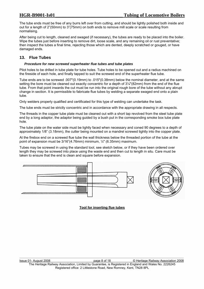
20. Record Keeping It is essential that accurate records are kept of all work carried out. A form such as that in RSP6 is included as an example in Appendix A and can be used to record work carried out on tubes.
21. Appendices A. Record Keeping
______________________________________ end of main document _______________________________________
HGR-B9001-Is01____________________________ Tubing of Locomotive Boilers
Issue 01- August 2008 page 18 of 18 © Heritage Railway Association 2008 The Heritage Railway Association, Limited by Guarantee, is Registered in England and Wales No. 2226245
Registered office: 2 Littlestone Road, New Romney, Kent, TN28 8PL
Appendix A Record Keeping
_________________________________________ end of appendix _________________________________________