Embed Size (px)
Citation preview
© MCRMA All rights reserved This edition GD 11 published 01/01/14
Guidance Document GD 11 January 2014
FIXINGS AND FASTENERS FOR RAINSCREEN SYSTEMS
INTRODUCTION
Every rainscreen or rear vented facade system is an arrangement of various layers
interconnected to each other to provide the overall thermal, weathering and aesthetic
appearance.
Integral to the success and the performance of rainscreen systems are the fastening
components ability to resist loadings and to interconnect the component parts from the
external facing materials back through the system to the structural supporting wall or
framework. Maintaining the performance and transmitting the loads and resisting dead, live
resistant and thermal loadings of the system are critical in the overall design and
performance criteria that is essential for every rainscreen application.
Fastener materials
Good practice dictates the use of non-ferrous materials with regard to fasteners used within
rainscreen build-ups and systems. These typically include stainless steels, aluminium and
plastics.
Structural fasteners for securing the frame and framing system should be made from
austenitic grades of stainless steel such as 304 or 316 or grade dependent upon the location
and application.
Aluminium fasteners such as rivets of a suitable aluminium grade and flange size are used
within systems primarily on the installation of the façade
Nylons and plastics are also used within rainscreen systems; especially with regards to
retention of the rainscreen insulation layer and when in conjunction with a screw set anchor
for installation of support brackets.

© MCRMA All rights reserved This edition GD 11 published 01/01/14
- 2 -
There are also façade systems on the market that utilise structural adhesives and hook on
systems.
The required performance of fasteners should be considered as a part of the initial system
specification. A combination of generic test data, system specific testing and on site testing
should all be considered by the structural engineer responsible for the system design to
ensure that the correct product type is selected to enable calculation of safe working loads
and fastener locations and the specific requirements of the system’s design criteria and
warranty requirements.
The uses and materials are application specific and as such are referenced where
appropriate within the specific product categories within this document.
The fastener components can be classified into four key areas:
1 Bracket to supporting wall or frame
2 Framing system fasteners
3 Insulation support anchors and fasteners
4 Façade fasteners
1 FASTENING OF SUPPORT SYSTEMS TO STRUCTURE
The type of frame bracket fastener is greatly dependent upon the substrate or frame that the
bracket requires to be secured to. The basic substrates are masonry or a framing system;
mother substrates can be used.
1.1 Masonry
Masonry substrates can consist of: - concrete dense, aerated or no-fines; brickwork, solid,
hollow of perforated; blockwork, solid, hollow or aerated structure. Where an existing
structure is concerned the substrate can vary and where a render or other system is applied
confirmation of the substrate may be complex. The wall’s structural ability to support a
rainscreen system and the point loads from brackets needs to be considered especially with
regards to an existing structure.

© MCRMA All rights reserved This edition GD 11 published 01/01/14
- 3 -
The general fastener types associated with this type of substrate are screw set anchors,
which comprise of an engineered nylon expansion plug and stainless steel screw and are
available with differing expansion zones and minimum embedment depths to suit the specific
substrate. Where more difficult substrates are identified such as weathered stone or other
friable materials other anchors may need to be considered such as torque controlled
anchors and resin anchors.
All masonry fasteners will require a pilot hole pre-drilled into the substrate prior to
installation. It is essential that the product manufacturer is consulted to establish the correct
hole size, embedment depth and clamping performance (build up thickness) and that the
fastener is suitable for the specific substrate.
Edge distances should also be considered - all these criteria can differ considerably
depending upon the actual substrate. Hole preparation should not be overlooked. One of the
most common causes of fastener failure in masonry is due to incorrect or lack of cleaning
once a pilot hole has been drilled. Manufacturers will reference the method for hole cleaning
for each of their own products.
Great care should also be taken to ensure that the existing substrate will offer sufficient
performance relevant to the proposed system requirement for fastener performance. This
can be determined by on-site pull out testing or generic test data. Again, consult the fastener
manufacturer.
Rainscreen fasteners for masonry can generally be split into the following types -
1.1.1 Screw set anchors
Screw set anchors are the most commonly used products for securing rainscreen brackets
to a wide variety of masonry substrates.
A screw set anchor consists of a 316 grade stainless steel screw and an engineered nylon
plug designed with an expansion zone to suit the embedment depth requirements of the
specific anchor to suit the substrate. The nylon expansion plug will have a collar that sits on
the face of the rainscreen bracket as the mechanical performance is generated from the
combined forces of the fastener and plug.

© MCRMA All rights reserved This edition GD 11 published 01/01/14
- 4 -
To ensure that the screw expands the plug correctly during installation a screw set anchor
with plugs with torsional protection should be selected.
Screw set anchors are designed to be installed with the screw being screwed into the plug;
the manufacturer’s installation instructions should be followed.
The screw set anchor should be chosen to suit the masonry substrate type as detailed in the
manufacturer’s literature or the associated European Technical Approval (ETA), and to suit
the performance criteria for the application. On-site testing is recommended to confirm the
anchors performance and suitability for the specific substrate.
The screw set anchor design with regards to the diameter plug flange and head style needs
to be checked for compatibility with the bracket type being installed and the manufacturer’s
installation instructions should be followed.
1.1.2 Through bolts and resin anchors In situations where screw set anchors or thread forming fasteners do not meet the required
performance with regard to the technical values achieved, where the substrate is deemed as
unsuitable or required edge distances are unachievable, then through bolts or resin anchors
should be considered.
Through bolts would generally be specified where a greater shear load is required although
their use is limited mostly to concrete with a high compressive strength. Care should be
taken to establish the concrete condition with regard to cracked or un-cracked concrete
before the appropriate fastener is selected.

© MCRMA All rights reserved This edition GD 11 published 01/01/14
- 5 - For less stable, friable or low compressive strength substrates or where cavities exist within
the masonry that cannot be accommodated by a screw set anchor, resin anchors should be
considered.
A wide range of resins are available and again great care should be taken when selecting a
product. On occasions, a mesh sleeve may be additionally required to ensure the fastener
performance meets the required values. As always, seek guidance from the manufacturer
and always choose a reputable supplier capable of providing comprehensive technical
advice and on-site support when considering using these products.
1.1.3 Thread forming fasteners
Fasteners are available which are ‘self-tapping’ and ‘thread form’ into a pre-drilled hole. The
shear, tensile and pull out values should all be considered at the point of design, together
with the fastener material which generally will need to be stainless steel or stainless steel bi-
metallic self-tapping anchor for aluminium brackets and for longevity of the overall system.
Thread forming fasteners are of a smaller diameter generally 6.5mm and 7.5mm than screw
set anchors. Thread forming fasteners must have a head size or washer suitable to support
the bracket/support section and resist pullover.

© MCRMA All rights reserved This edition GD 11 published 01/01/14
- 6 -
This type of anchor is only suitable to substrates that can accommodate a thread forming
fastener and produce a matting thread in the substrate and where this matting thread can be
retained. Therefore this type of anchor needs to be checked for suitability by the
structural/design engineer for the specific system/substrate.
1.2 Steel 1.2.1 Self-drilling fasteners
The most commonly used fastener for fixing rainscreen brackets or primary support rails
back to a light steel frame system is a self-drilling fastener. This is generally a bi-metallic
fastener comprising of a carbon steel drill point and lead threads welded to a stainless steel
threaded fastener.
It is essential when selecting a self-drilling fastener that the pull-out and shear performance
of the fastener is suitable to meet the design requirements of the rainscreen system and that
the correct length fastener is used to ensure that the stainless steel section of the fastener is
engaged into the steel substrate; therefore the manufacturer’s published grip/clamping range
should be adhered to. Self-drilling fasteners are available with and without a free spin zone.
The following factors need to be taken into account:
1 The thickness of the steel to be drilled
Bi-metallic self-drilling fasteners are manufactured with their own integral drill point which is
designed to drill and thread form into a pre-determined steel thickness typically in a range up
to 12-14mm. If the wrong product is selected for example, a fastener designed for 12mm
steel is used into 2.5mm steel, then the performance of the fastener will be dramatically
reduced due to the fact that the drill tip will create a much larger hole in the steel which, in
relationship to the fastener thread diameter, will result in minimal thread engagement. In
reverse, a fastener designed for thin steel used in thick steel will result in either the drill tip
‘burning out’ or the threads collapsing when the fastener tries to thread form as the hole
created is much too small.

© MCRMA All rights reserved This edition GD 11 published 01/01/14
- 7 -
2 The build-up thickness or ‘clamping range’
As with masonry fasteners, self-drilling fasteners are designed specifically to accommodate
a particular build-up range. It is essential that all layers (including voids) between the
underside of the fastener head and the backside of the steelwork are calculated; for example
a 3mm bracket + 12mm cement particle board + 2.5mm steel would equate to a build-up
thickness of 17.5mm. A fastener should therefore be selected with an ‘effective thread
length’ greater than 17.5mm.
The fastener manufacturer should be consulted if there is any doubt; this is to ensure that
the carbon steel drill tip is not in contact with any part of the steel work or build up. Once
installed all threads above and below the steel should be stainless steel.
1.2.2 Self tapping screws On occasions, steel will be too thick for commercially available drill screws to accommodate.
In this instance a self-tapping fastener should be selected. Whilst the build- up thickness
need not be considered in relation to accommodating the carbon steel drill tip, it is still
necessary to consult with the fastener manufacturer regarding the effective working thread
length. Thread forms on self-tappers will also vary depending on the thickness of steel to be
‘tapped’. Consult the manufacturer for guidance.

© MCRMA All rights reserved This edition GD 11 published 01/01/14
- 8 -
With regard to pilot hole diameters - this will be determined by the thickness of the steel in
relation to the diameter of the fastener. Good quality drill bits should be used but discarded
once they show sign of wear as this will affect the fastener performance.
1.2.3 Composite panels Increasingly, it is becoming more and more common to fasten rainscreen systems to the
face of composite panels. In most cases a structural rivet is the natural fastener choice but
through innovation by some manufacturers - self drilling fasteners are available for this
application, depending upon the panel type proposed. Whilst manufacturers can provide
technical details regarding the fastener performance in the panel, it is strongly recommended
that a designed system approach is taken regarding this application and that the panel
manufacturer is consulted to ensure that any bracket or rail system fixed to the face will be
secure and that the panel type is appropriate for the application/design to ensure panel
delamination and system failure is avoided.
1.3 Timber
When fixing to timber, both drill screws and self-tapping screws may be selected depending
on the thickness and type of timber to be fixed into. Timber used in construction can
generally be split into two types:
1 Solid timber, usually used as studwork, often structural.
2 Composite board, such as oriented strand board (OSB), plywood or any timber
product made up from layers of more than on piece of timber and bonded to form a
sheet or structural member such as cross laminated timber (CLT), structural
insulated panels (SIP) or Glulam beams.

© MCRMA All rights reserved This edition GD 11 published 01/01/14
- 9 -
When fixing into solid timber self-drilling fastener may be selected as the drill tip will form the
correct sized pilot hole and so give optimum performance and help stop the timber splitting,
or where a self-tapping fastener is used a pilot hole may be required depending upon the
type of substrate. When fixing through (or to) timber sheet materials it is advisable to
ascertain characteristic pull out values in these less structural boards.
Most manufacturers will advise on minimum embedment and edge distance requirements
and in all cases guidance can and should be sought from BS EN 1995-1-1:2004 + A1:2008 -
Eurocode 5; Design of timber structures.
1.4 Installation tooling All fasteners should be installed using the manufacturer’s recommended installation tool to
ensure that the correct installation speed and end loads are used for installation of the
selected fastener component. In addition, a depth locator should also be used to eliminate
the risk of overdriving which leads to thread stripping. All of the above will affect the
performance of the fastener in application which can ultimately lead to loss of function.
© MCRMA All rights reserved This edition GD 11 published 01/01/14
- 10 -
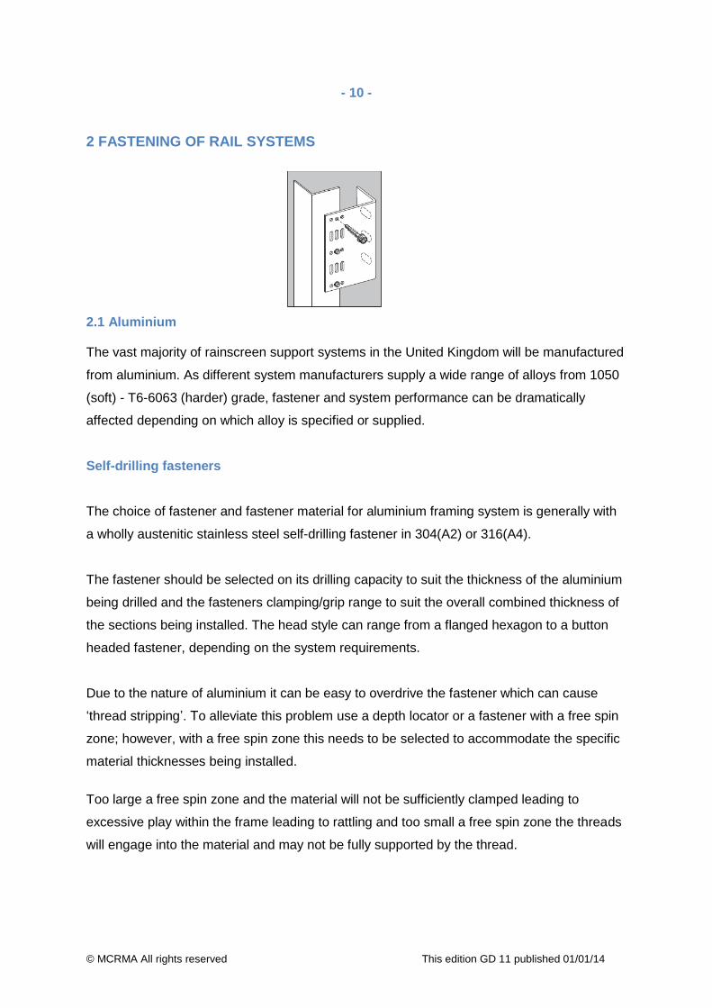
2 FASTENING OF RAIL SYSTEMS 2.1 Aluminium The vast majority of rainscreen support systems in the United Kingdom will be manufactured
from aluminium. As different system manufacturers supply a wide range of alloys from 1050
(soft) - T6-6063 (harder) grade, fastener and system performance can be dramatically
affected depending on which alloy is specified or supplied.
Self-drilling fasteners
The choice of fastener and fastener material for aluminium framing system is generally with
a wholly austenitic stainless steel self-drilling fastener in 304(A2) or 316(A4).
The fastener should be selected on its drilling capacity to suit the thickness of the aluminium
being drilled and the fasteners clamping/grip range to suit the overall combined thickness of
the sections being installed. The head style can range from a flanged hexagon to a button
headed fastener, depending on the system requirements.
Due to the nature of aluminium it can be easy to overdrive the fastener which can cause
‘thread stripping’. To alleviate this problem use a depth locator or a fastener with a free spin
zone; however, with a free spin zone this needs to be selected to accommodate the specific
material thicknesses being installed.
Too large a free spin zone and the material will not be sufficiently clamped leading to
excessive play within the frame leading to rattling and too small a free spin zone the threads
will engage into the material and may not be fully supported by the thread.

© MCRMA All rights reserved This edition GD 11 published 01/01/14
- 11 -
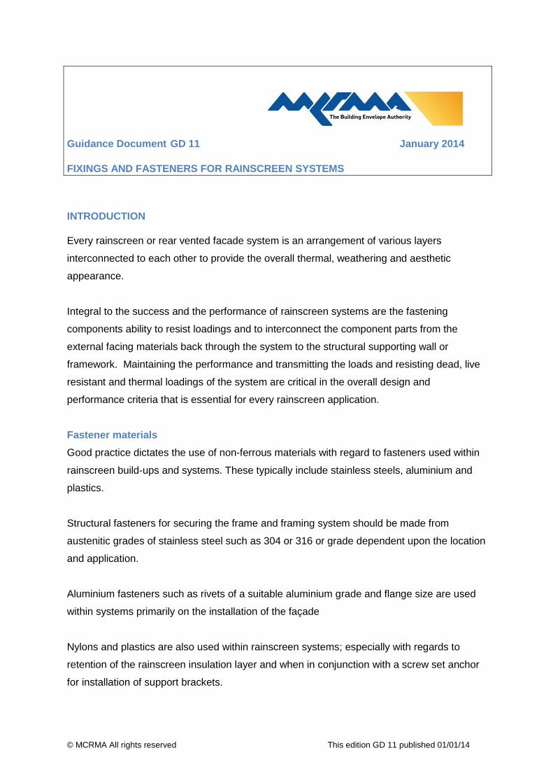
There are two type of fixing connections required; a fixed connection where two aluminium
sections are secured together with the fastener either going into a round hole in the first
section to be secured or drilling both sections and a floating/expansion connection where the
fastener is installed into a slotted hole in the first section and then drilling and tapping into
the second section. The location of fixed and floating points will be determined by the overall
design of the framing system.
Images courtesy of Nvelope Rainscreen Systems Limited
Rivets
Some framing systems can be installed with a rivet with a stand-off nosepiece. This will
effectively clamp the section whilst still allowing the required movement. The obvious
downside of this is the requirement to pre-drill the aluminium. The framing
manufacturers/designer should be consulted to ensure that a riveted framing system is
suitable for the loads of the overall rainscreen system design.
© MCRMA All rights reserved This edition GD 11 published 01/01/14
- 12 -
3 FASTENING OF INSULATION BOARDS
It is generally considered that the fixing of insulation boards is a non-structural application.
So whilst a less technical approach may be adopted it is worth noting that the insulation will
still be subjected to wind loads during construction and that regulations exist concerning
wind loads and fire regulations that must be adhered to.
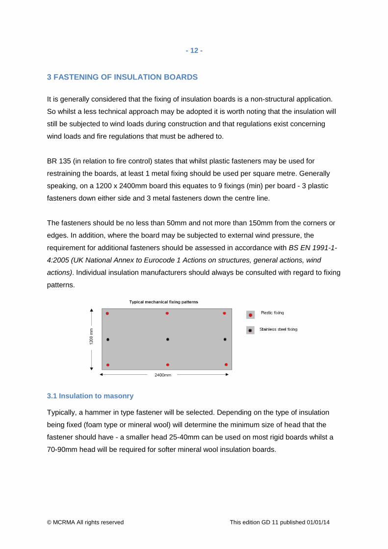
BR 135 (in relation to fire control) states that whilst plastic fasteners may be used for
restraining the boards, at least 1 metal fixing should be used per square metre. Generally
speaking, on a 1200 x 2400mm board this equates to 9 fixings (min) per board - 3 plastic
fasteners down either side and 3 metal fasteners down the centre line.
The fasteners should be no less than 50mm and not more than 150mm from the corners or
edges. In addition, where the board may be subjected to external wind pressure, the
requirement for additional fasteners should be assessed in accordance with BS EN 1991-1-
4:2005 (UK National Annex to Eurocode 1 Actions on structures, general actions, wind
actions). Individual insulation manufacturers should always be consulted with regard to fixing
patterns.
3.1 Insulation to masonry Typically, a hammer in type fastener will be selected. Depending on the type of insulation
being fixed (foam type or mineral wool) will determine the minimum size of head that the
fastener should have - a smaller head 25-40mm can be used on most rigid boards whilst a
70-90mm head will be required for softer mineral wool insulation boards.

© MCRMA All rights reserved This edition GD 11 published 01/01/14
- 13 -
Best practice recommends that the insulation manufacturer should be consulted for
guidance with regard to this. Pilot hole diameters and embedment depths should be
acquired from the fixing manufacturer and installation guidance should always be followed
exactly.
3.2 Insulation to steel, timber and sheathing board For these substrates, a plastic or stainless steel disc (fixing pattern as with masonry above)
in conjunction with the fastener appropriate to the substrate should be selected. Guidance
on fastener selection should be followed as above (see section 2, Fastening of rail systems).
It is becoming more common, and in some cases unavoidable, to fix insulation to sheathing
boards over steel frame. Best practice recommends fixing through the sheathing board and
into the steel/timber structure.
Where this is not possible, it is advisable to ascertain the fastener performance in the
sheathing board prior to installation as the different boards available will offer quite dramatic
differences in performance regarding resistance to fastener ‘pull out’.

© MCRMA All rights reserved This edition GD 11 published 01/01/14
- 14 -
4 FAÇADE FASTENERS
Many façade systems are available in the market ranging from granite, composite stone
materials and terracotta tiles to high pressure laminate (HPL) and rainscreen cladding
boards, though to aluminium cassette and aluminium composite materials (ACM).
Each system has its own attachment and fastener requirements which can range from
specialist undercut anchors, hanging and hook on brackets bracket systems to face or
recessed fixed fastener systems.
The specific façade manufacturer’s instructions and recommendations should be adhered to
with regards the method of attachment. Here we are concentrating of aluminium and ACM
panels, for other façade systems please contact the fastener manufacturer or system
supplier for specific fastener systems.
4.1 Aluminium and ACM
Generally aluminium and ACM facades systems are secured to an aluminium frame. The
main methods of attachment are from either a hook on system which hooks on to specialist
brackets or frame sections specifically designed to support the façade.
Some fixed point and/or through fixed points may be included within the overall design at
junctions or at capping details.
The main fixing methods for systems that are mechanically fixed are rivets and self-drilling
fasteners.

© MCRMA All rights reserved This edition GD 11 published 01/01/14
- 15 -
4.1.1 Rivets Best practice recommends that all panels are prepared with an oversized hole (in relation to
the proposed rivet diameter) by the fabricator. This should be calculated on the anticipated
expansion of the panel and sub-frame. The rivet which is then selected to fix the panel
should be accurately fixed in the centre of the panel hole to ensure that thermal/differential
movement between the panel and its supporting structure is accommodated.
The head diameter of the rivet should be of a size suitable to clamp the panel and of a size
to ensure that the hole is covered from view even after movement as taken place.
To achieve accurate installation of the fastener, use of a centering tool is recommended.
Variations of these tools are available from different manufacturers and offer differing levels
of accuracy.
When installing rivets, in addition to the centering tools, a stand-off nose piece should be
used. This will hold the rivet off the face of the panel usually by a fraction of a millimetre.
This ensures that the panel is securely clamped but not ‘locked’ as with framing and allows
the panel to naturally expand.
Having addressed the issue of allowing movement of the panel whilst securely attaching it to
the sub-frame, it must be noted that panels will also require a ‘fixed point’ to avoid slippage.
If all the holes in the panel are oversized and the fastener is ‘held off’ then the panel will slip.

© MCRMA All rights reserved This edition GD 11 published 01/01/14
- 16 -
To overcome this, the system designer should specify fixed points based on his calculations
with the fixed point pilot hole diameters being drilled in the appropriate places and clearance
holes for the floating point also being drilled in the appropriate places to the designer’s
requirements.
If no fixed points are allowed that is, all the holes are oversized, then a solution is available.
Fixed point sleeves are a simple and effective way to create the required fixed point in an
oversized hole. The system designer is responsible for dictating the location and the fastener
manufacturer will offer the appropriate sized sleeve to accommodate this.
4.1.2 Self-drilling/self-tapping fasteners Self-drilling fasteners can also be utilised in the installation of aluminium cassette panels and
ACM panels to either aluminium or timber framing systems. The same requirements for fixed
and floating point fasteners are required for self-drilling fasteners. Fasteners can be supplied
with a centering grommet to provide a floating point.
Some façade systems on the market provide, as with the framing system, slotted holes to
accommodate the thermal movement within the system and to accommodate self-drilling
fasteners without the need for specialist designed fasteners or for the installer to drill the
panel to accommodate the thermal movement.

© MCRMA All rights reserved This edition GD 11 published 01/01/14
- 17 -
With all aluminium rainscreen systems always consult the fastener manufacturer or the
aluminium system manufacturer prior to installation.
MCRMA RAINSCREEN GROUP The Rainscreen Group, formed from companies within MCRMA membership, includes the
principal companies who supply metal based systems and component parts used within the
fabrication and construction of rainscreen cladding systems.
Members of the group have been involved in the development of rainscreen systems over
many years and have an extensive knowledge of their use and application on all types of
buildings. In addition, the Rainscreen Group provides a technical focus for specifiers who
wish to use these highly aesthetic systems on prestigious new build developments or
refurbishment projects.
Members of the Rainscreen Group speak with authority on the subject, provide support
based on years of knowledge and give reliability in the systems they supply and
manufacture. For more information visit http://www.mcrma.co.uk/rainscreen.htm
DISCLAIMER
Whilst the information contained in this publication is believed to be correct at the time of publication, the Metal Cladding and Roofing Manufacturers Association Limited and its member companies cannot be held responsible for any errors or inaccuracies and, in particular, the specification for any application must be checked with the individual manufacturer concerned for a given installation. Information provided by the MCRMA or contained within publications and articles which are made available in any form (mechanical, electronic, photocopying or otherwise) cannot be used or cited as a means of ensuring that a material, product, system or assembly is compliant with Building Regulations.
©2014 MCRMA - 106 Ruskin Avenue, Rogerstone, Newport, South Wales NP10 0BD
Tel: 01633 895633 [email protected] www.mcrma.co.uk