Embed Size (px)
Citation preview

�
970A-G46/ 970S-G46ser�esMS-7693 (v2.x) Ma�nboard
G52-76931X4

��
Preface MS-7693
Preface
Preface MS-7693
Preface
Copyr�ght Not�ceThe mater�al �n th�s document �s the �ntellectual property of MICRO-STAR INTERNA-TIONAL. We take every care �n the preparat�on of th�s document, but no guarantee �s g�ven as to the correctness of �ts contents. Our products are under cont�nual �mprove-ment and we reserve the r�ght to make changes w�thout not�ce.
TrademarksAll trademarks �n th�s manual are propert�es of the�r respect�ve owners.
MSI® �s reg�stered trademark of M�cro-Star Int’l Co.,Ltd.NVIDIA® �s reg�stered trademark of NVIDIA Corporat�on.ATI® �s reg�stered trademark of AMD Corporat�on.AMD® �s reg�stered trademarks of AMD Corporat�on.Intel® �s reg�stered trademarks of Intel Corporat�on.W�ndows® �s reg�stered trademarks of M�crosoft Corporat�on.AMI® �s reg�stered trademark of Amer�can Megatrends Inc.Award® �s a reg�stered trademark of Phoen�x Technolog�es Ltd.Sound Blaster® �s reg�stered trademark of Creat�ve Technology Ltd.Realtek® �s reg�stered trademark of Realtek Sem�conductor Corporat�on.JM�cron® �s reg�stered trademark of JM�cron Technology Corporat�on.Netware® �s reg�stered trademark of Novell, Inc.Luc�d® �s trademark of Luc�dLog�x Technolog�es, Ltd.VIA® �s reg�stered trademark of VIA Technolog�es, Inc.ASMed�a® �s reg�stered trademark of ASMed�a Technology Inc.�Pad, �Phone, and �Pod are trademarks of Apple Inc.
Rev�s�on H�storyRev�s�on Rev�s�on H�story DateV2.0 F�rst release 2011/12
■■■■■■■■■■■■■■■■

Preface MS-7693
Preface
���
Preface MS-7693
Preface
Techn�cal SupportIf a problem ar�ses w�th your system and no solut�on can be obta�ned from the user’s manual, please contact your place of purchase or local d�str�butor. Alternat�vely, please try the follow�ng help resources for further gu�dance.
V�s�t the MSI webs�te for techn�cal gu�de, BIOS updates, dr�ver updates, and other �nformat�on: http://www.ms�.com/serv�ce/download
Contact our techn�cal staff at: http://support.ms�.com
Safety Instruct�onsAlways read the safety �nstruct�ons carefully.Keep th�s User’s Manual for future reference.Keep th�s equ�pment away from hum�d�ty.Lay th�s equ�pment on a rel�able flat surface before sett�ng �t up.The open�ngs on the enclosure are for a�r convect�on hence protects the equ�pment from overheat�ng. DO NOT COVER THE OPENINGS.Make sure the voltage of the power source �s at 110/220V before connect�ng the equ�pment to the power �nlet.Place the power cord such a way that people can not step on �t. Do not place any-th�ng over the power cord.Always Unplug the Power Cord before �nsert�ng any add-on card or module.All caut�ons and warn�ngs on the equ�pment should be noted.Never pour any l�qu�d �nto the open�ng that can cause damage or cause electr�cal shock.If any of the follow�ng s�tuat�ons ar�ses, get the equ�pment checked by serv�ce personnel:
The power cord or plug �s damaged.
L�qu�d has penetrated �nto the equ�pment.
The equ�pment has been exposed to mo�sture.
The equ�pment does not work well or you can not get �t work accord�ng to User’s Manual.
The equ�pment has been dropped and damaged.
The equ�pment has obv�ous s�gn of breakage.DO NOT LEAVE THIS EQUIPMENT IN AN ENVIRONMENT ABOVE 60oC (140oF), IT MAY DAMAGE THE EQUIPMENT.
◙
◙
■■■■■
■
■
■■■
■
◯
◯
◯
◯
◯
◯■
�v
Preface MS-7693
Preface
Preface MS-7693
Preface
FCC-B Rad�o Frequency Interference StatementTh�s equ�pment has been tested and found to comply w�th the l�m�ts for a Class B d�g�-tal dev�ce, pursuant to Part 15 of the FCC Rules. These l�m�ts are des�gned to prov�de reasonable protect�on aga�nst harmful �nter-ference �n a res�dent�al �nstallat�on. Th�s equ�pment generates, uses and can rad�ate rad�o frequency energy and, �f not �nstalled and used �n accordance w�th the �nstruc-t�ons, may cause harmful �nterference to rad�o commun�cat�ons. However, there �s no guarantee that �nterference w�ll not occur �n a part�cular �nstallat�on. If th�s equ�pment does cause harmful �nterference to rad�o or telev�s�on recept�on, wh�ch can be deter-m�ned by turn�ng the equ�pment off and on, the user �s encouraged to try to correct the �nterference by one or more of the measures l�sted below.
Reor�ent or relocate the rece�v�ng antenna.
Increase the separat�on between the equ�pment and rece�ver.
Connect the equ�pment �nto an outlet on a c�rcu�t d�fferent from that to wh�ch the rece�ver �s connected.
Consult the dealer or an exper�enced rad�o/telev�s�on techn�c�an for help.
Not�ce 1The changes or mod�ficat�ons not expressly approved by the party respons�ble for com-pl�ance could vo�d the user’s author�ty to operate the equ�pment.Not�ce 2Sh�elded �nterface cables and A.C. power cord, �f any, must be used �n order to comply w�th the em�ss�on l�m�ts.
VOIR LA NOTICE D’INSTALLATION AVANT DE RACCORDER AU RESEAU.
◯
◯
◯
◯
Th�s dev�ce compl�es w�th Part 15 of the FCC Rules. Operat�on �s subject to the follow-�ng two cond�t�ons:
th�s dev�ce may not cause harmful �nterference, and th�s dev�ce must accept any �nterference rece�ved, �nclud�ng �nterference that may cause undes�red operat�on.
1)2)
M�cro-Star Internat�onalMS-7693

Preface MS-7693
Preface
v
Preface MS-7693
Preface
Cal�forn�a, USA: The button cell battery may conta�n perchlorate mater�al and requ�res spec�al handl�ng when recycled or d�sposed of �n Cal�forn�a. For further �nformat�on please v�s�t:http://www.dtsc.ca.gov/hazardouswaste/perchlorate/
CAUTION: There �s a r�sk of explos�on, �f battery �s �ncorrectly replaced. Replace only w�th the same or equ�valent type recommended by the manufacturer.
Ta�wan: For better env�ronmental protect�on, waste batter�es should be collected separately for recycl�ng or spec�al d�sposal.
廢電池請回收
European Un�on: Batter�es, battery packs, and accumulators should not be d�sposed of as unsorted household waste. Please use the publ�c collect�on system to return, recycle, or treat them �n compl�ance w�th the local regulat�ons.
Battery Informat�on
Chem�cal Substances Informat�onIn compl�ance w�th chem�cal substances regulat�ons, such as the EU REACH Regula-t�on (Regulat�on EC No. 1907/2006 of the European Parl�ament and the Counc�l), MSI prov�des the �nformat�on of chem�cal substances �n products at:http://www.ms�.com/html/popup/csr/evmtprtt_pcm.html
BSMI EMI 聲明警告使用者:這是甲類資訊產品,在居住的環境中使用時,可能會造成無線電干擾,在這種情況下,使用者會被要求採取某些適當的對策。

v�
Preface MS-7693
Preface
Preface MS-7693
Preface
WEEE (Waste Electr�cal and Electron�c Equ�pment) Statement
ENGLISHTo protect the global env�ronment and as an env�ronmental�st, MSI must re-m�nd you that...Under the European Un�on (“EU”) D�rect�ve on Waste Electr�cal and Electron-�c Equ�pment, D�rect�ve 2002/96/EC, wh�ch takes effect on August 13, 2005, products of “electr�cal and electron�c equ�pment” cannot be d�scarded as mu-n�c�pal wastes anymore, and manufacturers of covered electron�c equ�pment w�ll be obl�gated to take back such products at the end of the�r useful l�fe. MSI w�ll com-ply w�th the product take back requ�rements at the end of l�fe of MSI-branded products that are sold �nto the EU. You can return these products to local collect�on po�nts.
DEUTSCHH�nwe�s von MSI zur Erhaltung und Schutz unserer UmweltGemäß der R�chtl�n�e 2002/96/EG über Elektro- und Elektron�k-Altgeräte dürfen Elek-tro- und Elektron�k-Altgeräte n�cht mehr als kommunale Abfälle entsorgt werden. MSI hat europawe�t versch�edene Sammel- und Recycl�ngunternehmen beauftragt, d�e �n d�e Europä�sche Un�on �n Verkehr gebrachten Produkte, am Ende se�nes Lebenszyklus zurückzunehmen. B�tte entsorgen S�e d�eses Produkt zum gegebenen Ze�tpunkt aus-schl�essl�ch an e�ner lokalen Altgerätesammelstelle �n Ihrer Nähe.
FRANÇAISEn tant qu’écolog�ste et afin de protéger l’env�ronnement, MSI t�ent à rappeler cec�...Au sujet de la d�rect�ve européenne (EU) relat�ve aux déchets des équ�pement élec-tr�ques et électron�ques, d�rect�ve 2002/96/EC, prenant effet le 13 août 2005, que les produ�ts électr�ques et électron�ques ne peuvent être déposés dans les décharges ou tout s�mplement m�s à la poubelle. Les fabr�cants de ces équ�pements seront obl�gés de récupérer certa�ns produ�ts en fin de v�e. MSI prendra en compte cette ex�gence relat�ve au retour des produ�ts en fin de v�e au se�n de la communauté européenne. Par con-séquent vous pouvez retourner localement ces matér�els dans les po�nts de collecte.
РУССКИЙКомпания MSI предпринимает активные действия по защите окружающей среды, поэтому напоминаем вам, что.... В соответствии с директивой Европейского Союза (ЕС) по предотвращению загрязнения окружающей среды использованным электрическим и электронным оборудованием (директива WEEE 2002/96/EC), вступающей в силу 13 августа 2005 года, изделия, относящиеся к электрическому и электронному оборудованию, не могут рассматриваться как бытовой мусор, поэтому производители вышеперечисленного электронного оборудования обязаны принимать его для переработки по окончании срока службы. MSI обязуется соблюдать требования по приему продукции, проданной под маркой MSI на территории EC, в переработку по окончании срока службы. Вы можете вернуть эти изделия в специализированные пункты приема.

Preface MS-7693
Preface
v��
Preface MS-7693
Preface
ESPAÑOLMSI como empresa compromet�da con la protecc�ón del med�o amb�ente, recom�enda:Bajo la d�rect�va 2002/96/EC de la Un�ón Europea en mater�a de desechos y/o equ�-pos electrón�cos, con fecha de r�gor desde el 13 de agosto de 2005, los productos clas�ficados como “eléctr�cos y equ�pos electrón�cos” no pueden ser depos�tados en los contenedores hab�tuales de su mun�c�p�o, los fabr�cantes de equ�pos electrón�cos, están obl�gados a hacerse cargo de d�chos productos al term�no de su período de v�da. MSI estará compromet�do con los térm�nos de recog�da de sus productos vend�dos en la Un�ón Europea al final de su per�odo de v�da. Usted debe depos�tar estos productos en el punto l�mp�o establec�do por el ayuntam�ento de su local�dad o entregar a una empresa autor�zada para la recog�da de estos res�duos.
NEDERLANDSOm het m�l�eu te beschermen, w�l MSI u eraan her�nneren dat….De r�chtl�jn van de Europese Un�e (EU) met betrekk�ng tot Vervu�l�ng van Electr�sche en Electron�sche producten (2002/96/EC), d�e op 13 Augustus 2005 �n zal gaan kun-nen n�et meer beschouwd worden als vervu�l�ng. Fabr�kanten van d�t soort producten worden verpl�cht om producten retour te nemen aan het e�nd van hun levenscyclus. MSI zal overeenkomst�g de r�chtl�jn handelen voor de producten d�e de merknaam MSI dragen en verkocht z�jn �n de EU. Deze goederen kunnen geretourneerd worden op lokale �nzamel�ngspunten.
SRPSKIDa b� zašt�t�l� pr�rodnu sred�nu, � kao preduzeće koje vod� računa o okol�n� � pr�rodnoj sred�n�, MSI mora da vas podest� da…Po D�rekt�v� Evropske un�je (“EU”) o odbačenoj ekektronskoj � elektr�čnoj oprem�, D�-rekt�va 2002/96/EC, koja stupa na snagu od 13. Avgusta 2005, pro�zvod� koj� spadaju pod “elektronsku � elektr�čnu opremu” ne mogu v�še b�t� odbačen� kao ob�čan otpad � pro�zvođač� ove opreme b�će pr�nuđen� da uzmu natrag ove pro�zvode na kraju nj�hovog uob�čajenog veka trajanja. MSI će poštovat� zahtev o preuz�manju ovakv�h pro�zvoda koj�ma je �stekao vek trajanja, koj� �maju MSI oznaku � koj� su prodat� u EU. Ove pro�z-vode možete vrat�t� na lokaln�m mest�ma za pr�kupljanje.
POLSKIAby chron�ć nasze środow�sko naturalne oraz jako firma dbająca o ekolog�ę, MSI przy-pom�na, że...Zgodn�e z Dyrektywą Un�� Europejsk�ej (“UE”) dotyczącą odpadów produktów elektry-cznych � elektron�cznych (Dyrektywa 2002/96/EC), która wchodz� w życ�e 13 s�erpn�a 2005, tzw. “produkty oraz wyposażen�e elektryczne � elektron�czne “ n�e mogą być trak-towane jako śm�ec� komunalne, tak w�ęc producenc� tych produktów będą zobow�ązan� do odb�eran�a �ch w momenc�e gdy produkt jest wycofywany z użyc�a. MSI wypełn� wymagan�a UE, przyjmując produkty (sprzedawane na teren�e Un�� Europejsk�ej) wy-cofywane z użyc�a. Produkty MSI będz�e można zwracać w wyznaczonych punktach zb�orczych.

v���
Preface MS-7693
Preface
Preface MS-7693
Preface
TÜRKÇEÇevrec� özell�ğ�yle b�l�nen MSI dünyada çevrey� korumak �ç�n hatırlatır:Avrupa B�rl�ğ� (AB) Kararnames� Elektr�k ve Elektron�k Malzeme Atığı, 2002/96/EC Kararnames� altında 13 Ağustos 2005 tar�h�nden �t�baren geçerl� olmak üzere, elektr�kl� ve elektron�k malzemeler d�ğer atıklar g�b� çöpe atılamayacak ve bu elekton�k c�hazların üret�c�ler�, c�hazların kullanım süreler� b�tt�kten sonra ürünler� ger� toplamakla yükümlü olacaktır. Avrupa B�rl�ğ�’ne satılan MSI markalı ürünler�n kullanım süreler� b�tt�ğ�nde MSI ürünler�n ger� alınması �steğ� �le �şb�rl�ğ� �çer�s�nde olacaktır. Ürünler�n�z� yerel toplama noktalarına bırakab�l�rs�n�z.
ČESKYZáleží nám na ochraně ž�votního prostředí - společnost MSI upozorňuje...Podle směrn�ce Evropské un�e (“EU”) o l�kv�dac� elektr�ckých a elektron�ckých výrobků 2002/96/EC platné od 13. srpna 2005 je zakázáno l�kv�dovat “elektr�cké a elektron�cké výrobky” v běžném komunálním odpadu a výrobc� elektron�ckých výrobků, na které se tato směrn�ce vztahuje, budou pov�nn� odebírat takové výrobky zpět po skončení je-j�ch ž�votnost�. Společnost MSI splní požadavky na odebírání výrobků značky MSI, prodávaných v zemích EU, po skončení jej�ch ž�votnost�. Tyto výrobky můžete odevzdat v místních sběrnách.
MAGYARAnnak érdekében, hogy környezetünket megvédjük, �lletve környezetvédőként fellépve az MSI emlékeztet� Önt, hogy ...Az Európa� Un�ó („EU”) 2005. augusztus 13-án hatályba lépő, az elektromos és elek-tron�kus berendezések hulladéka�ról szóló 2002/96/EK �rányelve szer�nt az elektromos és elektron�kus berendezések többé nem kezelhetőek lakosság� hulladékként, és az �lyen elektron�kus berendezések gyártó� kötelessé válnak az �lyen termékek v�sszavé-telére azok hasznos élettartama végén. Az MSI betartja a termékv�sszavétellel kapc-solatos követelményeket az MSI márkanév alatt az EU-n belül értékesített termékek esetében, azok élettartamának végén. Az �lyen termékeket a legközelebb� gyűjtőhelyre v�het�.
ITALIANOPer proteggere l’amb�ente, MSI, da sempre am�ca della natura, t� r�corda che….In base alla D�rett�va dell’Un�one Europea (EU) sullo Smalt�mento de� Mater�al� Elettr�c� ed Elettron�c�, D�rett�va 2002/96/EC �n v�gore dal 13 Agosto 2005, prodott� appartenent� alla categor�a de� Mater�al� Elettr�c� ed Elettron�c� non possono p�ù essere el�m�nat� come r�fiut� mun�c�pal�: � produttor� d� dett� mater�al� saranno obbl�gat� a r�t�rare ogn� prodotto alla fine del suo c�clo d� v�ta. MSI s� adeguerà a tale D�rett�va r�t�rando tutt� � prodott� march�at� MSI che sono stat� vendut� all’�nterno dell’Un�one Europea alla fine del loro c�clo d� v�ta. È poss�b�le portare � prodott� nel p�ù v�c�no punto d� raccolta

Preface MS-7693
Preface
�x
Preface MS-7693
Preface
CONTENTS▍Copyr�ght Not�ce ............................................................................................ ��Trademarks .................................................................................................... ��Rev�s�on H�story............................................................................................. ��Techn�cal Support..........................................................................................���Safety Instruct�ons .........................................................................................���FCC-B Rad�o Frequency Interference Statement.......................................... �vBattery Informat�on ......................................................................................... vChem�cal Substances Informat�on .................................................................. vBSMI EMI 聲明 ............................................................................................... vWEEE (Waste Electr�cal and Electron�c Equ�pment) Statement ................... v�Chapter 1 Gett�ng Started............................................................................1-1
Pack�ng Contents ................................................................................................. 1-2Opt�onal Accessor�es ........................................................................................... 1-2Assembly Precaut�ons .......................................................................................... 1-3Ma�nboard Spec�ficat�ons ..................................................................................... 1-4Connectors Qu�ck Gu�de ...................................................................................... 1-6Back Panel Qu�ck Gu�de ...................................................................................... 1-8CPU (Central Process�ng Un�t) .......................................................................... 1-10Mount�ng Screw Holes ....................................................................................... 1-13Power Supply ..................................................................................................... 1-14Memory .............................................................................................................. 1-15Expans�on Slots ................................................................................................. 1-17V�deo/ Graph�cs Cards ...................................................................................... 1-18Internal Connectors ............................................................................................ 1-23Jumpers ............................................................................................................. 1-28LED Status Ind�cators ........................................................................................ 1-29
Chapter 2 BIOS Setup .................................................................................2-1Enter�ng ................................................................................................................ 2-2Overv�ew .............................................................................................................. 2-2Boot dev�ce pr�or�ty bar ........................................................................................ 2-3Operat�on ............................................................................................................. 2-4SETTINGS ........................................................................................................... 2-5OC ...................................................................................................................... 2-10ECO ................................................................................................................... 2-16BROWSER ......................................................................................................... 2-17Install�ng W�nk� ................................................................................................... 2-17

x
Preface MS-7693
Preface
UTILITIES .......................................................................................................... 2-18Updat�ng the BIOS w�th L�ve Update .................................................................. 2-20SECURITY ......................................................................................................... 2-21
Append�x A Realtek Aud�o .......................................................................... A-1Install�ng the Realtek HD Aud�o Dr�ver .................................................................A-2Software Configurat�on .........................................................................................A-3Hardware Default Sett�ng .....................................................................................A-5
Append�x B AMD RAID............................................................................... B-1RAID Configurat�on ..............................................................................................B-2

Thank you for choos�ng the 970A-G46/ 970S-G46 Ser�es (MS-7693 v2.X) ATX ma�nboard. The Ser�es ma�nboards are based on AMD® 970 & SB950 ch�pset for opt�mal system effic�ency. Des�gned to fit the advanced AMD® AM3/ AM3+ processor, the 970A-G46/ 970S-G46 Ser�es ma�nboards del�ver a h�gh performance and profess�onal desktop platform solut�on.
Chapter 1
Gett�ng Started

1-2
Gett�ng Started
Pack�ng Contents
* These p�ctures are for reference only and may vary w�thout not�ce.* The pack�ng contents may vary accord�ng to the model you purchased.* If you need to purchase the opt�onal accessor�es or request part numbers, please v�s�t the MSI webs�te at http://www.ms�.com/�ndex.php or consult the dealer.
Ma�nboard Dr�vers & Ut�l�t�es D�sc User Gu�de Backplate
SATA Cable
M-ConnectorUSB3 to USB2
ConnectorSATA Power
Cable
USB 2.0 Bracket
USB 3.0 Bracket
Opt�onal Accessor�es
SLI Cable
eSATA Power Cable
CrossF�re Cable
eSATA Bracket

1-3
MS-7693
Chapter 1
Assembly Precaut�onsThe components �ncluded �n th�s package are prone to damage from electrostat�c d�scharge (ESD). Please adhere to the follow�ng �nstruct�ons to ensure successful computer assembly. Always turn off the power supply and unplug the power cord from the power outlet before �nstall�ng or remov�ng any computer component.Ensure that all components are securely connected. Loose connect�ons may cause the computer to not recogn�ze a component or fa�l to start. Hold the ma�nboard by the edges to avo�d touch�ng sens�t�ve components. It �s recommended to wear an electrostat�c d�scharge (ESD) wr�st strap when handl�ng the ma�nboard to prevent electrostat�c damage. If an ESD wr�st strap �s not ava�lable, d�scharge yourself of stat�c electr�c�ty by touch�ng another metal object before han-dl�ng the ma�nboard. Store the ma�nboard �n an electrostat�c sh�eld�ng conta�ner or on an ant�stat�c pad whenever the ma�nboard �s not �nstalled. Before turn�ng on the computer, ensure that there are no loose screws or metal com-ponents on the ma�nboard or anywhere w�th�n the computer case.Do not use the computer �n a h�gh-temperature env�ronment.Do not boot the computer before �nstallat�on �s completed. Th�s could cause perma-nent damage to the components as well as �njury to the user. If you need help dur�ng any �nstallat�on step, please consult a cert�fied computer tech-n�c�an.
ImportantA screwdr�ver (not �ncluded) may be requ�red for computer assembly.
■
■
■
■■
■
■
■■
■

1-4
Gett�ng Started
Ma�nboard Spec�ficat�ons
Processor SupportAMD® PhenomTM II, AthlonTM and Sempron processor �n the AM3/ AM3+ package.(For the latest �nformat�on about CPU, please v�s�t http://www.ms�.com/serv�ce/cpu-support)
Ch�psetAMD® 970 & SB950 ch�pset
Memory Support4x DDR3 DIMMs support DDR3 2133*(OC)/ 1866/ 1600/ 1333/ 1066 DRAM (32GB Max)Supports Quad-Channel mode, one DIMM per channel(*OC = OverClock�ng, for more �nformat�on on compat�ble components, please v�s�t http://www.ms�.com/serv�ce/test-report)
LANSupports LAN 10/100/1000 Fast Ethernet by Realtek® RTL8111E
Aud�oIntegrated HD aud�o codec by Realtek® ALC8928-channel aud�o w�th jack sens�ng
SATA6x SATA 6Gb/s ports by AMD® SB950
RAIDSATA1~6 support RAID 0/ 1/ 5/ 10 by AMD® SB950
USB 3.02x USB 3.0 rear IO ports by ASMed�a® ASM1042
Mult�-GPUSupports ATI® CrossF�reXTM TechnologySupports NVIDIA® SLITM Technology
■
■
■
■
■
■■
■
■
■
■■
1-5
MS-7693
Chapter 1
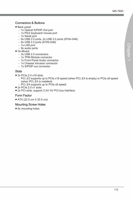
Connectors & ButtonsBack panel
1x Opt�cal S/PDIF-Out port1x PS/2 keyboard/ mouse port1x Ser�al port6x USB 2.0 ports, 2x USB 3.0 ports (970A-G46)8x USB 2.0 ports (970S-G46)1x LAN port6x aud�o ports
On-Board3x USB 2.0 connectors1x TPM Module connector1x Front Panel Aud�o connector1x Chass�s Intrus�on connector1x S/PDIF-out connector
Slots2x PCIe 2.0 x16 slots
PCI_E2 supports up to PCIe x16 speed (when PCI_E4 �s empty) or PCIe x8 speed (when PCI_E4 �s �nstalled)PCI_E4 supports up to PCIe x8 speed
2x PCIe 2.0 x1 slots2x PCI slots, support 3.3V/ 5V PCI bus Interface
Form FactorATX (22.5 cm X 30.5 cm)
Mount�ng Screw Holes6x mount�ng holes
■-------
■-----
■-
-■■
■
■

1-6
Gett�ng Started
Connectors Qu�ck Gu�de
BackPanel
CPU CPUFANJPWR2
JPWR1
JFP2JUSB3
JAUD1
JCI1
PCI_E1SYSFAN1
SATA3/4
PCI_E2
PCI_E3
PCI_E4
DIMM2
DIMM1
DIMM3
DIMM4
JTPM1
SATA5/6
SATA2
SATA1
JBAT1
JFP1
JUSB2
JUSB1JSP1
PCI1
PCI2
SYSFAN2

1-7
MS-7693
Chapter 1
Connectors Reference Gu�dePort Name Port Type Page
Back Panel 1-8
CPU AM3+ CPU Socket 1-9
CPUFAN CPU Fan Connector 1-24
JAUD1 Front Panel Aud�o Connector 1-25
JBAT1 Clear CMOS Jumper 1-28
JCI1 Chass�s Intrus�on Connector 1-26
JFP1, JFP2 Front Panel Connectors 1-25
JPWR1 ATX 24-p�n Power Connector 1-14
JPWR2 ATX 8-p�n Power Connector 1-14
JSP1 S/PDIF-Out Connector 1-27
JTPM1 TPM Module connector 1-27
JUSB1~3 USB 2.0 Expans�on Connectors 1-26
PCI1,2 PCI Expans�on Slots 1-17
PCI_E2,4 PCIe x16 Expans�on Slots 1-17
PCI_E1,3 PCIe x1 Expans�on Slots 1-17
SATA1~6 SATA 6Gb/s Connectors 1-23
SYSFAN1~2 System Fan Connectors 1-24

1-8
Gett�ng Started
Back Panel Qu�ck Gu�de
Opt�cal S/PDIF-OutTh�s S/PDIF (Sony & Ph�l�ps D�g�tal Interconnect Format) connector �s prov�ded for d�g�tal aud�o transm�ss�on to external speakers through an opt�cal fiber cable.
Mouse/KeyboardA comb�nat�on PS/2® mouse/keyboard DIN connector for a PS/2® mouse/keyboard.
Ser�al PortThe ser�al port �s a 16550A h�gh speed commun�cat�ons port that sends/ rece�ves 16bytes FIFOs. You can attach a ser�al mouse or other ser�al dev�ces d�rectly to the connector.
USB 2.0 PortThe USB 2.0 port �s for attach�ng USB 2.0 dev�ces such as keyboard, mouse, or other USB 2.0-compat�ble dev�ces.
USB 3.0 Port (970A-G46)USB 3.0 port �s backward-compat�ble w�th USB 2.0 dev�ces. It supports data transfer rate up to 5 Gb�t/s (SuperSpeed).
ImportantIn order to use USB 3.0 dev�ces, you must connect to a USB 3.0 port. If a USB cable �s used, �t must be USB 3.0 compl�ant.
▶
▶
▶
▶
▶
Opt�cal S/PDIF-Out
L�ne-In
L�ne-Out
M�c
RS-Out
CS-Out
SS-Out
USB 2.0 Port
USB 3.0 Port (970A-G46)USB 2.0 Port (970S-G46)
LAN
Mouse/Keyboard
Ser�al Port
USB 2.0 Port

1-9
MS-7693
Chapter 1
LAN The standard RJ-45 LAN jack �s for connect�ng to a Local Area Network (LAN).
LED Color LED State Cond�t�on
Left Yellow Off LAN l�nk �s not establ�shed.
On(Steady) LAN l�nk �s establ�shed.
On(flash�ng) The computer �s commun�cat�ng w�th another computer on the network.
R�ght Green Off 10 Mb�ts/sec data rate
On 100 Mb�ts/sec data rate
Orange On 1000 Mb�ts/sec data rate
Aud�o PortsThese connectors are used for aud�o dev�ces. The color of the jack refers to the funct�on of the connector.
Blue-L�ne �n: Used for connect�ng external aud�o outputt�ng dev�ces.Green- L�ne out: Used as a connector for speakers or headphone.P�nk- M�c: Used as a connector for a m�crophone.Black- RS-Out: Rear surround sound l�ne out �n 4/ 5.1/ 7.1 channel mode.Orange- CS-Out: Center/ subwoofer l�ne out �n 5.1/ 7.1 channel mode.Gray- SS-Out: S�de surround sound l�ne out �n 7.1 channel mode.
▶
▶
■■■■■■
Yellow Green/ Orange

1-10
Gett�ng Started
Gold arrow
Introduct�on to AM3/ AM3+ CPUThe surface of CPU. Remember to apply some thermal paste on �t for better heat d�spers�on.
CPU (Central Process�ng Un�t)
ImportantOverheat�ngOverheat�ng can ser�ously damage the CPU and ma�nboard. Always make sure the cool�ng fans work properly to protect the CPU from overheat�ng. Be sure to apply an even layer of thermal paste (or thermal tape) between the CPU and the heats�nk to enhance heat d�ss�pat�on.Replac�ng the CPUWhen replac�ng the CPU, always turn off the system’s power supply and unplug the power supply’s power cord to ensure the safety of the CPU.Overclock�ngTh�s ma�nboard �s des�gned to support overclock�ng. Before attempt�ng to overclock, please make sure that all other system components can tolerate overclock�ng. Any attempt to operate beyond product spec�ficat�ons �s not recommend. MSI does not guarantee the damages or r�sks caused by �nadequate operat�on beyond product spec�ficat�ons.

1-11
MS-7693
Chapter 1
CPU & Cooler Installat�onWhen you are �nstall�ng the CPU, make sure the CPU has a cooler attached on the top to prevent overheat�ng. Meanwh�le, do not forget to apply some thermal paste on CPU before �nstall�ng the heat s�nk/cooler fan for better heat d�spers�on. Follow the steps below to �nstall the CPU & cooler correctly. Wrong �nstallat�on w�ll cause the damage of your CPU & ma�nboard.
Pull the lever s�deways away from the socket. Make sure to ra�se the lever up to a 90-degree angle.
1. Look for the gold arrow of the CPU. The gold arrow should po�nt as shown �n the p�cture. The CPU can only fit �n the correct or�entat�on.
2.
If the CPU �s correctly �nstalled, the p�ns should be completely embedded �nto the socket and can not be seen. Please note that any v�olat�on of the correct �nstallat�on procedures may cause permanent damages to your ma�nboard.
3. Press the CPU down firmly �nto the socket and close the lever. As the CPU �s l�kely to move wh�le the lever �s be�ng closed, always close the lever w�th your fingers press�ng t�ghtly on top of the CPU to make sure the CPU �s properly and completely embedded �nto the socket.
4.
1-12
Gett�ng Started
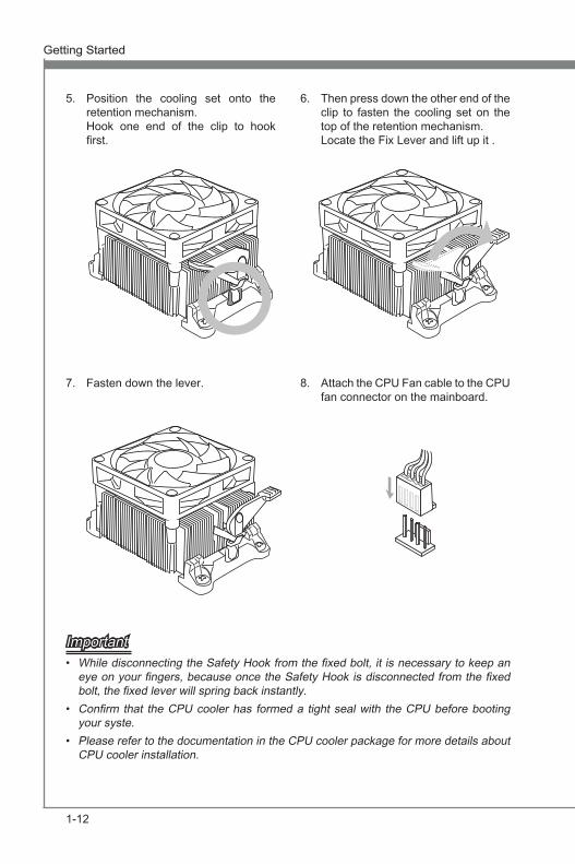
Pos�t�on the cool�ng set onto the retent�on mechan�sm. Hook one end of the cl�p to hook first.
5. Then press down the other end of the cl�p to fasten the cool�ng set on the top of the retent�on mechan�sm. Locate the F�x Lever and l�ft up �t .
6.
Fasten down the lever.7. Attach the CPU Fan cable to the CPU fan connector on the ma�nboard.
8.
ImportantWh�le d�sconnect�ng the Safety Hook from the fixed bolt, �t �s necessary to keep an eye on your fingers, because once the Safety Hook �s d�sconnected from the fixed bolt, the fixed lever w�ll spr�ng back �nstantly.Confirm that the CPU cooler has formed a t�ght seal w�th the CPU before boot�ng your syste.Please refer to the documentat�on �n the CPU cooler package for more deta�ls about CPU cooler �nstallat�on.
•
•
•

1-13
MS-7693
Chapter 1
Mount�ng Screw HolesWhen �nstall�ng the ma�nboard, first �nstall the necessary mount�ng stands requ�red for an ma�nboard on the mount�ng plate �n your computer case. If there �s an I/O back plate that came w�th the computer case, please replace �t w�th the I/O backplate that came w�th the ma�nboard package. The I/O backplate should snap eas�ly �nto the computer case w�thout the need for any screws. Al�gn the mount�ng plate’s mount�ng stands w�th the screw holes on the ma�nboard and secure the ma�nboard w�th the screws prov�ded w�th your computer case. The locat�ons of the screw holes on the ma�nboard are shown below. For more �nformat�on, please refer to the manual that came w�th the computer case.
ImportantInstall the ma�nboard on a flat surface free from unnecessary debr�s. To prevent damage to the ma�nboard, any contact between the ma�nboard c�rcu�try and the computer case, except for the mount�ng stands, �s proh�b�ted.Please make sure there are no loose metal components on the ma�nboard or w�th�n the computer case that may cause a short c�rcu�t of the ma�nboard.
••
•
The I/O ports should be fac�ng tow
ard the rear of the com
puter case. They should l�ne up w
�th the holes on the I/O
backplate.

1-14
Gett�ng Started
Power SupplyJPWR1: ATX 24-p�n Power Connector Th�s connector allows you to connect an ATX 24-p�n power supply. To connect the ATX 24-p�n power supply, al�gn the power supply cable w�th the connector and firmly press the cable �nto the connector. If done correctly, the cl�p on the power cable should be hooked on the ma�nboard’s power connector.
13.+3.3V
1.+3.3V
14.-12V
2.+3.3V
15.Ground
3.Ground
16.PS-ON#
4.+5V
17.Ground
5.Ground
18.Ground
6.+5V
19.Ground
7.Ground
22.+5V
10.+12V
20.Res
8.PWR OK
23.+5V
11.+12V
21.+5V
9.5VSB
24.Ground
12.+3.3V
JPWR2 : ATX 8-p�n Power ConnectorTh�s connector prov�des 12V power to the CPU.
7.+12V
3.Ground
5.+12V
1.Ground8.+12V
4.Ground
6.+12V
2.Ground
ImportantMake sure that all the power cables are securely connected to a proper ATX power sup-ply to ensure stable operat�on of the ma�nboard.

1-15
MS-7693
Chapter 1
MemoryThese DIMM slots are used for �nstall�ng memory modules. For more �nformat�on on compat�ble components, please v�s�t http://www.ms�.com/serv�ce/test-report
DDR3240-p�n, 1.5V
48x2=96 p�n 72x2=144 p�n
Dual-Channel mode Populat�on RuleIn Dual-Channel mode, the memory modules can transm�t and rece�ve data w�th two data bus channels s�multaneously. Enabl�ng Dual-Channel mode can enhance system performance. The follow�ng �llustrat�ons expla�n the populat�on rules for Dual-Channel mode.
1
DIMM1
DIMM2
DIMM3
DIMM4
2
DIMM1
DIMM2
DIMM3
DIMM4
InstalledEmpty
ImportantDDR3 memory modules are not �nterchangeable w�th DDR2, and the DDR3 standard �s not backward compat�ble. Always �nstall DDR3 memory modules �n DDR3 DIMM slots.In Dual-Channel mode, make sure that you �nstall memory modules of the same type and dens�ty �n d�fferent channel DIMM slots.To enable successful system boot-up, always �nsert the memory modules �nto the DIMM4/ DIMM2 first.Due to ch�pset resource usage, the system w�ll only detect up to 31+ GB of memory (not full 32 GB) when all DIMM slots have 8GB memory modules �nstalled.
•
•
•
•

1-16
Gett�ng Started
Install�ng Memory ModulesUnlock the DIMM slot by push�ng the mount�ng cl�p to the s�de. Vert�cally �nsert the memory module �nto the DIMM slot. The memory module has an off-center notch on the bottom that w�ll only allow �t to fit one way �nto the DIMM slot.Push the memory module deep �nto the DIMM slot. The plast�c cl�p at s�de of the DIMM slot w�ll automat�cally close when the memory module �s properly seat and an aud�ble cl�ck should be heard.Manually check �f the memory module has been locked �n place by the DIMM slot’s s�de cl�p.
Notch
Volt
1.
2.
3.

1-17
MS-7693
Chapter 1
Expans�on SlotsTh�s ma�nboard conta�ns numerous ports for expans�on cards, such as d�screte graph-�cs or aud�o cards.
PCIe (Per�pheral Component Interconnect Express) SlotThe PCIe slot supports the PCIe �nterface expans�on card.
PCIe 2.0 x16 Slot
PCIe x1 Slot
PCI (Per�pheral Component Interconnect) SlotThe PCI slot supports add�t�onal LAN, SCSI, USB, and other add-on cards that comply w�th PCI spec�ficat�ons.
32-b�t PCI Slot
PCI Interrupt Request Rout�ngIRQ, or �nterrupt request l�nes, are hardware l�nes over wh�ch dev�ces can send �nterrupt requests to the processor. The PCI IRQ p�ns are typ�cally connected to the PCI bus p�ns as followed:
Order1 Order2 Order3 Order4PCI Slot1 INT E# INT F# INT G# INT H#PCI Slot2 INT F# INT G# INT H# INT E#
ImportantWhen add�ng or remov�ng expans�on cards, always turn off the power supply and un-plug the power supply power cable from the power outlet. Read the expans�on card’s documentat�on to check for any necessary add�t�onal hardware or software changes.

1-18
Gett�ng Started
V�deo/ Graph�cs Cards If ava�lable, th�s ma�nboard takes advantage of the CPU’s �ntegrate graph�cs processor, but d�screte v�deo cards can be �nstalled by way of the ma�nboard’s expans�on slots. Add�ng on one or more d�screte v�deo cards w�ll s�gn�ficantly boost the system’s graph�cs performance. For best compat�b�l�ty, MSI graph�cs cards are recommended.S�ngle V�deo Card Installat�on
Determ�ne what type of expans�on slot(s) the v�deo card w�ll use. Locate the expans�on slot(s) on the ma�nboard. Remove any protect�ve expans�on slot covers from the computer case. L�ne up the v�deo card on top of the expans�on slot(s) w�th the d�splay ports fac�ng out of the computer case. For a s�ngle v�deo card �nstallat�on, us�ng the PCI_E2 slot �s recommended. Push the v�deo card �nto �ts expans�on slot(s). Depend�ng on the expans�on slot(s) used, there should be cl�p(s) on the expans�on slot(s) that w�ll lock �n place.If needed, screw the edge of the graph�cs card to the computer case. Some v�deo cards m�ght requ�re a power cable d�rectly from the power supply.Please consult your v�deo card’s manual for further �nstruct�ons regard�ng dr�ver �nstallat�on or other spec�al sett�ngs.
1.
2.
3.
4.
5.

1-19
MS-7693
Chapter 1
AMD CrossF�reX™ (Mult�-GPU) TechnologyAMD CrossF�reX™ �s a mult�-GPU performance gam�ng platform. By l�nk�ng together two or more d�screte GPUs, CrossF�reX™ can s�gn�ficant �mprove system graph�cs performance. It allows the ab�l�ty to scale a system’s graph�cs power as needed, mak�ng �t the most scalable gam�ng platform. Th�s ma�nboard w�ll automat�cally detect CrossF�reX™ technology and make changes �n the BIOS as needed. Follow the �nstruct�ons below to ensure a successful two-way CrossF�reX™ �nstallat�on.
Install two AMD Radeon™ HD graph�cs cards �nto the PCI_E2 & PCI_E4 expans�on slots.W�th the two cards �nstalled, two CrossF�reX™ V�deo L�nk cable are requ�red to connect the graph�cs cards. Attach one s�de of the cable on each of the cards by way of the metal contacts (please refer to the p�cture below). Please note that although two graph�cs cards have been �nstalled, only the d�splay ports on the graph�cs card �nstalled �n the first PCIe x16 slot w�ll work. All d�splays should be connected to th�s graph�cs card.
1.
2.
CrossF�reXTM V�deo L�nk cable
ImportantPlease ensure that all graph�cs cards used �n CrossF�reX™ mode are of the same brand and spec�ficat�ons. For best compat�b�l�ty w�th the ma�nboard, MSI graph�cs cards are recommended.Make sure to connect an adequate power supply to the power connectors on the graph�cs cards to ensure stable operat�on. Only W�ndows™ V�sta, & W�ndows™ 7 w�ll support CrossF�reX™ mode.
•
•
•

1-20
Gett�ng Started
Boot up the computer and �nstall the dr�vers and software �ncluded �n your v�deo card package. For more �nformat�on, please refer to the manual that came w�th your v�deo card. After all of the hardware and software has been properly �nstalled, reboot the system. After enter�ng the operat�ng system (OS), r�ght cl�ck on the desktop and choose the “Catalyst Control Center II”.
3.
4.
The CrossF�reX™ sett�ng must be enabled to allow CrossF�reX™ mode to operate. The follow screen appears �n the Catalyst Control Center II. Depend�ng on your operat�ng system, the screen may look d�fferent.
5.
ImportantA CrossF�reXTM system has four poss�ble d�splay modes:
SuperT�l�ngSc�ssor ModeAlternate Frame Render�ngSuper Ant�-al�as�ng.
For more deta�ls, please consult the graph�cs card manual.
••••

1-21
MS-7693
Chapter 1
NVIDIA® SLI TechnologyNVIDIA’s SLI (Scalable L�nk Interface) technology allows two or more GPUs to run �n tandem w�th�n a system to ach�eve s�gn�ficant graph�cs performance ga�ns. To ut�l�ze th�s technology, the GPU cards must be connected by an SLI V�deo L�nk.If you �ntend to use SLI mode, please follow the �nstruct�ons below to properly set up SLI mode. The �nstruct�ons below are meant for a two v�deo card SLI configurat�on.
Install two NVIDIA graph�cs cards �n the PCI_E2 and the PCI_E4 slots. W�th the two cards �nstalled, a SLI V�deo L�nk cable �s requ�red to connect the graph�cs cards. Attach one s�de of the cable on each of the cards by way of the metal contacts (please refer to the p�cture below). Please note that although two graph�cs cards have been �nstalled, only the d�splay ports on the graph�cs card �nstalled �n the first PCIe x16 slot w�ll work. All d�splays should be connected to th�s graph�cs card.
1.2.
Boot up the computer and �nstall the dr�vers and software �ncluded �n your v�deo card package. For more �nformat�on, please refer to the manual that came w�th your v�deo card.
3.
SLI V�deo L�nk Card

1-22
Gett�ng Started
After all of the hardware and software has been properly �nstalled, reboot the system. After enter�ng the operat�ng system (OS), r�ght cl�ck on the desktop and choose the “NVIDIA Control Panel”.
4.
Enter the NVIDIA Control Panel. Choose the “Max�m�ze 3D Performance” sett�ng to enable SLI mode. The configurat�on screen �s shown below. Depend�ng on your operat�ng system, the screen may look d�fferent.
5.
ImportantPlease ensure that all graph�cs cards used �n SLI mode are of the same brand and spec�ficat�ons. For best compat�b�l�ty w�th the ma�nboard, MSI graph�cs cards are recommended.Make sure to connect an adequate power supply to the power connectors on the graph�cs cards to ensure stable operat�on. If you w�sh to remove one graph�cs card and qu�t the SLI funct�on, make sure the “Max�m�ze 3D Performance” funct�on �s d�sable before remov�ng the graph�cs card.
•
•
•
Choose th�s �tem

1-23
MS-7693
Chapter 1
Internal ConnectorsSATA1~6: SATA ConnectorTh�s connector �s a h�gh-speed SATA �nterface port. Each connector can connect to one SATA dev�ce. SATA dev�ces �nclude d�sk dr�ves (HDD), sol�d state dr�ves (SSD), and opt�cal dr�ves (CD/ DVD/ Blu-Ray).
* The MB layout �n th�s figure �s for reference only.
SATA1~6 (6Gb/s, by AMD® SB950)
SATA6SATA5SATA1
SATA2 SATA4SATA3
ImportantMany SATA dev�ces also need a power cable from the power supply. Such dev�ces �nclude d�sk dr�ves (HDD), sol�d state dr�ves (SSD), and opt�cal dr�ves (CD / DVD / Blu-Ray). Please refer to the dev�ce’s manual for further �nformat�on. Many computer cases also requ�re that large SATA dev�ces, such as HDDs, SSDs, and opt�cal dr�ves, be screwed down �nto the case. Refer to the manual that came w�th your computer case or your SATA dev�ce for further �nstallat�on �nstruct�ons. Please do not fold the SATA cable at a 90-degree angle. Data loss may result dur�ng transm�ss�on otherw�se.SATA cables have �dent�cal plugs on e�ther s�des of the cable. However, �t �s rec-ommended that the flat connector be connected to the ma�nboard for space sav�ng purposes.
•
•
•
•

1-24
Gett�ng Started
CPUFAN,SYSFAN1~2: Fan Power ConnectorsThe fan power connectors support system cool�ng fans w�th +12V. If the ma�nboard has a System Hardware Mon�tor ch�pset on-board, you must use a spec�ally des�gned fan w�th a speed sensor to take advantage of the CPU fan control. Remember to connect all system fans. Some system fans may not connect to the ma�nboard and w�ll �nstead connect to the power supply d�rectly. A system fan can be plugged �nto any ava�lable system fan connector.
SYSFAN1
1.Ground2.+12V
3.Sensor/ No UseSYSFAN2
1.Ground2.+12V
3.Sensor4.Control
CPUFAN
1.Ground2.Control
3.Sensor4.No use
ImportantPlease refer to your processor’s offic�al webs�te or consult your vendor to find recommended CPU cool�ng fans. The CPUFAN connectors support Smart Fan Control w�th l�ner mode. The Control Center II ut�l�ty can be �nstalled to automat�cally control the fan speeds accord�ng to the CPU’s and system’s temperature. If there are not enough ports on the ma�nboard to connect all system fans, adapters are ava�lable to connect a fan d�rectly to a power supply. Before first boot up, ensure that there are no cables �mped�ng any fan blades.
•
•
•
•

1-25
MS-7693
Chapter 1
JFP1, JFP2: Front Panel ConnectorsThese connectors connect to the front panel sw�tches and LEDs. The JFP1 connector �s compl�ant w�th the Intel® Front Panel I/O Connect�v�ty Des�gn Gu�de. When �nstall�ng the front panel connectors, please use the enclosed mConnectors to s�mpl�fy �nstallat�on. Plug all the w�res from the computer case �nto the mConnectors and then plug the mConnectors �nto the ma�nboard.
1.+3.-
10.No Pin
5.-Reset Switch
HDD LED
Power SwitchPower LED
7.+9.Reserved
8.-6.+4.-2.+
JFP1
1.Ground
3.Suspend LED
5.Power LED
7.No Pin
8.+6.-4.+2.-
BuzzerSpea
ker
JFP2
ImportantOn the connectors com�ng from the case, p�ns marked by small tr�angles are pos�t�ve w�res. Please use the d�agrams above and the wr�t�ng on the mConnectors to determ�ne correct connector or�entat�on and placement. The major�ty of the computer case’s front panel connectors w�ll pr�mar�ly be plugged �nto JFP1.
JAUD1: Front Panel Aud�o ConnectorTh�s connector allows you to connect the front aud�o panel located on your computer case. Th�s connector �s compl�ant w�th the Intel® Front Panel I/O Connect�v�ty Des�gn Gu�de.
1.MIC L
3.MIC R
10.Head Phone Detection
5.Head Phone R
7.SENSE_SEND
9.Head Phone L
8.No Pin6.MIC Detection
4.NC2.Ground
•
•

1-26
Gett�ng Started
JUSB1~3: USB 2.0 Expans�on ConnectorsTh�s connector �s des�gned for connect�ng h�gh-speed USB per�pherals such as USB HDDs, d�g�tal cameras, MP3 players, pr�nters, modems, and many others.
115
V
1.VCC
3.USB0-
10.NC
5.USB0+
7.Ground
9.No Pin
8.Ground6.USB1+
4.USB1-2.VCC
* The MB layout �n th�s figure �s for reference only.
USB 2.0 Bracket (opt�onal)
ImportantNote that the VCC and GND p�ns must be connected correctly to avo�d poss�ble dam-age.
JCI1: Chass�s Intrus�on ConnectorTh�s connector connects to the chass�s �ntrus�on sw�tch cable. If the computer case �s opened, the chass�s �ntrus�on mechan�sm w�ll be act�vated. The system w�ll record th�s �ntrus�on and a warn�ng message w�ll flash on screen. To clear the warn�ng, you must enter the BIOS ut�l�ty and clear the record.
1.CINTRU
2.Ground

1-27
MS-7693
Chapter 1
JTPM1: TPM Module connectorTh�s connector connects to a TPM (Trusted Platform Module). Please refer to the TPM secur�ty platform manual for more deta�ls and usages.
* The MB layout �n th�s figure �s for reference only.
1 15V
10.No Pin
14.Ground8.5V Power
12.Ground6.Serial IRQ
4.3.3V Power
2.3V Standby power
1.LPC Clock
3.LPC Reset
5.LPC address & data pin0
7.LPC address & data pin1
9.LPC address & data pin2
11.LPC address & data pin3
13.LPC Frame
TPM module �s opt�onal
JSP1: S/PDIF-Out Connector Th�s connector �s used to connect S/PDIF (Sony & Ph�l�ps D�g�tal Interconnect Format) �nterface for d�g�tal aud�o transm�ss�on.
115
V
3.VCC
2.SPDIF
1.Ground
* The MB layout �n th�s figure �s for reference only.
S/PDIF-Out Bracket (opt�onal)

1-28
Gett�ng Started
JumpersJBAT1: Clear CMOS Jumper There �s CMOS RAM onboard that �s external powered from a battery located on the ma�nboard to save system configurat�on data. W�th the CMOS RAM, the system can automat�cally boot �nto the operat�ng system (OS) every t�me �t �s turned on. If you want to clear the system configurat�on, set the jumpers to clear the CMOS RAM.
JBAT1 Keep Data Clear Data
1 11
ImportantYou can clear CMOS by short�ng 2-3 p�n wh�le the system �s off. Then return to 1-2 p�n pos�t�on. Avo�d clear�ng the CMOS wh�le the system �s on; �t w�ll damage the ma�nboard.

1-29
MS-7693
Chapter 1
LED Status Ind�cators
CPU_PHASE LEDs
CPU_PHASE LEDsThese LEDs �nd�cate the current CPU power phase mode. Follow the �nstruct�ons below to read.
L�ghts Off
CPU �s �n 1 phase power mode.
CPU �s �n 2 phase power mode.
CPU �s �n 3 phase power mode.
CPU �s �n 4 phase power mode.


CLICK BIOS II �s a revolut�onary UEFI �nterface that allows you to setup and configure your system for opt�mum use. Us�ng your mouse and keyboard, users can change BIOS sett�ngs, mon�tor CPU temperature, select the boot dev�ce pr�or�ty and v�ew system �nformat�on such as the CPU name, DRAM capac�ty, the OS vers�on and the BIOS vers�on. Users can �mport and export parameter data for backup or for shar�ng w�th fr�ends. By connect�ng to the Internet w�th�n CLICK BIOS II, users can browse webpages, check ma�l and use L�ve Update �your system.
Chapter 2
BIOS Setup

2-2
BIOS Setup MS-7693
Chapter 2
BIOS Setup MS-7693
Chapter 2
Enter�ngPower on the computer and the system w�ll start the Power On Self Test (POST) pro-cess. When the message below appears on the screen, please <DEL> key to enter CLICK BIOS II:
Press DEL key to enter Setup Menu, F11 to enter Boot Menu
If the message d�sappears before you respond and you st�ll need to enter CLICK BIOS II, restart the system by turn�ng the computer OFF then back ON or press�ng the RESET button. You may also restart the system by s�multaneously press�ng <Ctrl>, <Alt>, and <Delete> keys.
ImportantThe �tems under each BIOS category descr�bed �n th�s chapter are under cont�nuous update for better system performance. Therefore, the descr�pt�on may be sl�ghtly d�ffer-ent from the latest BIOS and should be held for reference only.
Overv�ewAfter enter�ng CLICK BIOS II, the follow�ng screen �s d�splayed.
BIOS menu select�on
Temperaturemon�tor
System�nformat�on
Boot dev�cepr�or�ty bar
Menu d�splay
Boot menu
BIOS menu select�on
Modeselect�on
ImportantThe p�ctures �n th�s gu�de are for reference only and may vary from the product you pur-chased. Please refer to the actual screens of your system for deta�led �nformat�on.
Temperature mon�torTh�s block shows the temperature of the processor and the ma�nboard.▶
BIOS Setup MS-7693
Chapter 2
2-3
BIOS Setup MS-7693
Chapter 2
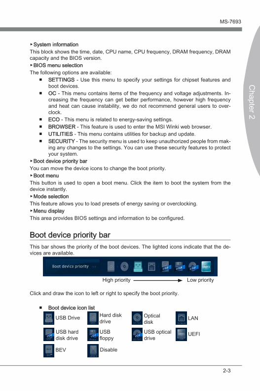
System �nformat�onTh�s block shows the t�me, date, CPU name, CPU frequency, DRAM frequency, DRAM capac�ty and the BIOS vers�on.
BIOS menu select�onThe follow�ng opt�ons are ava�lable:
SETTINGS - Use th�s menu to spec�fy your sett�ngs for ch�pset features and boot dev�ces.OC - Th�s menu conta�ns �tems of the frequency and voltage adjustments. In-creas�ng the frequency can get better performance, however h�gh frequency and heat can cause �nstab�l�ty, we do not recommend general users to over-clock. ECO - Th�s menu �s related to energy-sav�ng sett�ngs.BROWSER - Th�s feature �s used to enter the MSI W�nk� web browser.UTILITIES - Th�s menu conta�ns ut�l�t�es for backup and update.SECURITY - The secur�ty menu �s used to keep unauthor�zed people from mak-�ng any changes to the sett�ngs. You can use these secur�ty features to protect your system.
Boot dev�ce pr�or�ty barYou can move the dev�ce �cons to change the boot pr�or�ty.
Boot menuTh�s button �s used to open a boot menu. Cl�ck the �tem to boot the system from the dev�ce �nstantly.
Mode select�onTh�s feature allows you to load presets of energy sav�ng or overclock�ng.
Menu d�splayTh�s area prov�des BIOS sett�ngs and �nformat�on to be configured.
Boot dev�ce pr�or�ty barTh�s bar shows the pr�or�ty of the boot dev�ces. The l�ghted �cons �nd�cate that the de-v�ces are ava�lable.
H�gh pr�or�ty Low pr�or�ty
Cl�ck and draw the �con to left or r�ght to spec�fy the boot pr�or�ty.
Boot dev�ce �con l�stOpt�cald�sk
USB Dr�ve Hard d�skdr�ve LAN
UEFIUSB opt�caldr�ve
USB hard d�sk dr�ve
USBfloppy
BEV D�sable
▶
▶
■
■
■■■■
▶
▶
▶
▶
■

2-4
BIOS Setup MS-7693
Chapter 2
BIOS Setup MS-7693
Chapter 2
Operat�onCLICK BIOS II allows you to control BIOS sett�ngs w�th the mouse and the keyboard. The follow�ng table l�sts and descr�bes the hot keys and the mouse operat�ons.
Hot key Mouse Descr�pt�on<↑↓→← >
Move the cursor
Select Item
<Enter>
Cl�ck/ Double-cl�ck the left button
Select Icon/ F�eld
<Esc>
Cl�ck the r�ght button
Jump to the Ex�t menu or return to the prev�ous from a submenu
<+> Increase the numer�c value or make changes<-> Decrease the numer�c value or make changes<F1> General Help<F4> CPU Spec�ficat�ons<F5> Enter Memory-Z<F6> Load opt�m�zed defaults<F10> Save Change and Reset<F12> Save a screenshot to a FAT/FAT32 USB dr�ve
Sub-MenuIf you find a po�nt symbol to the left of certa�n fields, that means a sub-menu can be launched for ad-d�t�onal opt�ons. You can use the arrow keys or mouse to h�ghl�ght the field and press <Enter> or double-cl�ck the left mouse button to enter the sub-menu. If you want to return to the prev�ous menu, just press <Esc> or cl�ck the r�ght mouse button.General HelpThe General Help screen l�sts the appropr�ate keys to use for nav�gat�on. You can call up th�s screen from any menu by s�mply press�ng <F1>. Press <Esc> to ex�t the Help screen.

BIOS Setup MS-7693
Chapter 2
2-5
BIOS Setup MS-7693
Chapter 2
SETTINGS
System StatusSystem Date
Th�s allows you to set the system date that you want (usually the current date).The format �s <day> <month> <date> <year>. day Day of the week, from Sun to Sat, determ�ned by BIOS. Read-only. month The month from Jan. through Dec. date The date from 1 to 31 can be keyed by numer�c funct�on keys. year The year can be adjusted by users.
System T�meTh�s allows you to set the system t�me that you want (usually the current t�me). The t�me format �s <hour> <m�nute> <second>.
SATA Port1~6Shows dev�ces connected to spec�fic SATA ports.
ImportantIf your dev�ce �s not d�splayed, turn off computer and re-check SATA cable and power cable connect�ons to the dev�ce.
System Informat�onShows deta�led system �nformat�on, �nclud�ng CPU type, BIOS vers�on, and Memory (read only).
▶
▶
▶
▶

2-6
BIOS Setup MS-7693
Chapter 2
BIOS Setup MS-7693
Chapter 2
AdvancedPCI Subsystem Sett�ngs
Press <Enter> to enter the sub-menu. PCI Latency T�mer
Controls how long each PCI dev�ce can hold the bus before another takes over.When set to h�gher values, every PCI dev�ce can conduct transact�ons for a longer t�me and thus �mprove the effect�ve PCI bandw�dth.
ACPI Sett�ngsPress <Enter> to enter the sub-menu.
ACPI Standby StateSpec�fies the power sav�ng mode for ACPI funct�on[S1] Sleep Mode. Hardware rema�ns on.[S3] Suspend to RAM. Turns off hardware. (Recommended)
Power LEDConfigures how the system uses power LEDs on the case to �nd�cate sleep/suspend state. [S�ngle] The power LED turns off dur�ng the sleep/suspend mode.[Dual] The power LED changes �ts color to �nd�cate the sleep/suspend
state.[Bl�nk�ng] The power LED bl�nks to �nd�cate the sleep/suspend state.
Integrated Per�pheralsPress <Enter> to enter the sub-menu.
Onboard LAN ControllerTh�s �tem allows you to enable/ d�sable the onboard LAN controller.
LAN Opt�on ROMTh�s �tem �s used to dec�de whether to �nvoke the Boot ROM of the onboard LAN.
SATA ModeTh�s �tem �s used to spec�fy RAID/ IDE/ AHCI mode for SATA port.
ImportantYou cannot sw�tch between AHCI and IDE �f you already have your operat�ng system �nstalled. If you have �nstalled your OS us�ng AHCI and you clear your BIOS/reset to default sett�ngs, you w�ll need to change th�s funct�on back to AHCI to ensure proper funct�onal�ty.
Port 1~6 Hot PlugThese �tems are used to enable/ d�sable the SATA ports hot plug support.
HD Aud�o ControllerTh�s �tem allows you to enable/ d�sable the HD aud�o controller.
HPETThe HPET (H�gh Prec�s�on Event T�mers) �s a component that �s part of the ch�pset.You can enable �t, and w�ll prov�de you w�th the means to get to �t v�a the var�ous
▶
▶
▶
▶
▶
▶
▶
▶
▶
▶
▶
▶

BIOS Setup MS-7693
Chapter 2
2-7
BIOS Setup MS-7693
Chapter 2
ACPI methods.USB Configurat�on
Press <Enter> to enter the sub-menu. USB Controller
Th�s �tem allows you to enable/ d�sable the �ntegrated USB 2.0 controller. Legacy USB Support
Enable or d�sable support for USB keyboards, m�ce and floppy dr�ves. You w�ll be able to use these dev�ces w�th operat�ng systems that do not support USB.
Onboard USB 3.0 ControllerTh�s �tem allows you to enable/ d�sable the USB 3.0 controller.
Super IO Configurat�onPress <Enter> to enter the sub-menu.
Ser�al(COM) Port 0 Configurat�onPress <Enter> to enter the sub-menu.
Ser�al (COM) Port0Th�s �tem allows you to enable/ d�sable the ser�al port.
Ser�al (COM) Port0 Sett�ngsSelect an address and correspond�ng �nterrupt for the ser�al port.
Hardware Mon�torPress <Enter> to enter the sub-menu.
CPU Smart Fan TargetControls CPU fan speed automat�cally depend�ng on the current temperature and to keep �t w�th a spec�fic range. If the current CPU temperature reaches the target value, the smart fan funct�on w�ll be act�vated.
SYS Fan1 ControlTh�s �tem allows user to select how percentage of speed for the SYSFAN1.
Power Management SetupPress <Enter> to enter the sub-menu.
EuP 2013Energy Us�ng Products Lot 6 2013 (EUP) reduces power consumpt�on when system �s off or �n standby mode.Note: When enabled, the system w�ll not support RTC wake up event funct�ons.
Restore after AC Power LossTh�s �tem spec�fies whether your system w�ll reboot after a power fa�lure or �nterrupt occurs. Sett�ngs are:[Power Off] Always leaves the computer �n the power off state.[Power On] Always leaves the computer �n the power on state.[Last State] Restore the system to the status before power fa�lure or �nterrupt
occurred.
▶
▶
▶
▶
▶
▶
▶
▶
▶
▶
▶
▶
▶
▶

2-8
BIOS Setup MS-7693
Chapter 2
BIOS Setup MS-7693
Chapter 2
Wake Up Event SetupPress <Enter> to enter the sub-menu.
Wake Up Event BySett�ng to [BIOS] act�vates the follow�ng fields, and use the follow�ng fields to set the wake up events. Sett�ng to [OS], the wake up events w�ll be defined by OS.
Resume By RTC AlarmThe field �s used to enable or d�sable the feature of boot�ng up the system on a scheduled t�me/date.
Date/ HH:MM:SSIf Resume By RTC Alarm �s set to [Enabled], the system w�ll automat�cally resume (boot up) on a spec�fic date/hour/m�nute/second spec�fied �n these fields (us�ng the <+> and <-> to select the date & t�me sett�ngs).
Resume By PCI or PCI-E Dev�ce When set to [Enabled], the feature allows your system to be awakened from the power sav�ng modes through any event on PCI or PCIe dev�ce.
Resume From S3 by USB Dev�ceThe �tem allows the act�v�ty of the USB dev�ce to wake up the system from S3 (Sus-pend to RAM) sleep state.
Resume From S3/S4/S5 by PS/2 Mouse/ KeyboardThese �tems determ�ne whether the system w�ll be awakened from what power sav-�ng modes when �nput s�gnal of the PS/2 mouse/ keyboard �s detected.
BootFull Screen Logo D�splay
[Enabled] The OS boots stra�ght to the GUI w�thout show�ng the POST screen,[D�sabled] Shows the POST messages at boot.== Boot Opt�on Pr�or�t�es==
1st~9th BootThese �tems are used to pr�or�t�ze the �nstalled boot dev�ces.
CD/DVD ROM Dr�ve BBS Pr�or�t�es/ USB KEY Dr�ve BBS Pr�or�t�es/ UEFI Boot Dr�ve BBS Pr�or�t�es
1st~9th BootThese �tems are used to pr�or�t�ze the �nstalled CD/DVD ROM/ USB key dr�ves/ UEFI boot dr�ves.
Save & Ex�tD�scard Changes and Ex�t
Use th�s �tem to abandon all changes and ex�t setup.Save Changes and Reset
Use th�s �tem to save changes and reset the system.Save Changes
Use th�s �tem to save changes.
▶
▶
▶
▶
▶
▶
▶
▶
▶
▶
▶
▶
▶
▶

BIOS Setup MS-7693
Chapter 2
2-9
BIOS Setup MS-7693
Chapter 2
D�scard ChangesUse th�s �tem to abandon all changes.
Restore DefaultsUse th�s �tem to load the opt�m�zed default values set by the BIOS vendor.== Boot Overr�de ==The �nstalled storage dev�ces w�ll appear on th�s menu, you can select one of them be a boot dev�ce.
Bu�lt-�n EFI ShellUse th�s �tem to enter the EFI Shell.
▶
▶
▶

2-10
BIOS Setup MS-7693
Chapter 2
BIOS Setup MS-7693
Chapter 2
OC
ImportantOverclock�ng your PC manually �s only recommended for advanced users.Overclock�ng �s not guaranteed, and �f done �mproperly, can vo�d your warranty or severely damage your hardware.If you are unfam�l�ar w�th overclock�ng, we adv�se you to use OC Gen�e for easy overclock�ng.
Current CPU/ DRAM Frequency These �tems show the current clocks of CPU and Memory speed. Read-only.
Adjust CPU FSB FrequencyTh�s �tem �s used to adjust the CPU FSB frequency (�n MHz).
Adjust CPU Rat�oTh�s �tem �s used to adjust CPU clock mult�pl�er (rat�o). It �s ava�lable only when the processor supports th�s funct�on.
Adjusted CPU FrequencyIt shows the adjusted CPU frequency. Read-only.
Adjust CPU-NB Rat�oTh�s �tem �s used to adjust CPU-NB rat�o.
Adjusted CPU-NB FrequencyIt shows the adjusted CPU-NB frequency. Read-only.
OC Gen�e L�teSett�ng th�s �tem to [Enabled] allows the system to detect the max�mum FSB clock and
••
•
▶
▶
▶
▶
▶
▶
▶

BIOS Setup MS-7693
Chapter 2
2-11
BIOS Setup MS-7693
Chapter 2
to overclock automat�cally. If overclock�ng fa�ls to run, you can try the lower FSB clock for overclock�ng successfully.
CPU Smart Protect�onCPU Smart Protect�on �s a mechan�sm of CPU overheat�ng protect�on. It w�ll automat�cally reduce the clock when the CPU temperature gets too hot.
Unlock CPU CoreTh�s �tem �s used to unlock the CPU core. Please refer to the procedures below for CPU core unlocked �n BIOS setup.
Success
Enter “OC” and set “Unlock CPU Core” to [Enabled].
Save changes and ex�t the BIOS setup.
System restart.
You w�ll see the “X4” (quad core) or “X2” (dual core for Sempron ser�es only) dur�ng POST.
Fa�l
Set “Adjust CPU-NB Rat�o” and “HT L�nk Speed” to [x8].
AMD Phenom(tm) II X4 Processor
Clear CMOS data.
The CPU does not support CPU core unlock�ng, please leave the default sett�ngs for system.
AMD Sempron(tm) II X2 Processor
ImportantTh�s CPU core unlocked behav�or depends on the CPU ab�l�ty/ character�st�c, and �t �s not guaranteed.Depend on CPU’s character�st�c, once you get �nstable scenar�o, please restore the default sett�ngs for system.You can also check the core numbers �n performance tab of W�ndows task manager.
CPU Core ControlTh�s �tem allows you to select the number of act�ve processor cores.
DRAM FrequencyTh�s �tem allows you to adjust the DRAM frequency. Please note the overclock�ng behav�or �s not guaranteed.
Adjusted DRAM FrequencyIt shows the adjusted DRAM frequency. Read-only.
DRAM T�m�ng ModeSelect whether DRAM t�m�ng �s controlled by the SPD (Ser�al Presence Detect) EEPROM on the DRAM module. Sett�ng to [Auto] enables DRAM t�m�ngs and the follow�ng “Advanced DRAM Configurat�on” sub-menu to be determ�ned by BIOS based on the configurat�ons on the SPD. Select�ng [L�nk] or [Unl�nk] allows users to configure
▶
▶
•
•
•
▶
▶
▶
▶
2-12
BIOS Setup MS-7693
Chapter 2
BIOS Setup MS-7693
Chapter 2
the DRAM t�m�ngs for each channel and the follow�ng related “Advanced DRAM Configurat�on” sub-menu manually.
Advanced DRAM Configurat�onPress <Enter> to enter the sub-menu.
Command RateTh�s sett�ng controls the DRAM command rate.
tCLControls CAS latency wh�ch determ�nes the t�m�ng delay (�n clock cycles) of start�ng a read command after rece�v�ng data.
tRCDDeterm�nes the t�m�ng of the trans�t�on from RAS (row address strobe) to CAS (column address strobe). The less clock cycles, the faster the DRAM performance.
tRPControls number of cycles for RAS (row address strobe) to be allowed to pre-charge. If �nsuffic�ent t�me �s allowed for RAS to accumulate before DRAM refresh, the DRAM may fa�l to reta�n data. Th�s �tem appl�es only when synchronous DRAM �s �nstalled �n the system.
tRASDeterm�nes the t�me RAS (row address strobe) takes to read from and wr�te to memory cell.
tRFCTh�s sett�ng determ�nes the t�me RFC takes to read from and wr�te to a memory cell.
tWRDeterm�nes m�n�mum t�me �nterval between end of wr�te data burst and the start of a pre-charge command. Allows sense ampl�fiers to restore data to cell.
tWTRDeterm�nes m�n�mum t�me �nterval between the end of wr�te data burst and the start of a column-read command; allows I/O gat�ng to overdr�ve sense ampl�fies before read command starts.
tRRDSpec�fies the act�ve-to-act�ve delay of d�fferent banks.
tRTPT�me �nterval between a read and a precharge command.
tFAWTh�s �tem �s used to set the tFAW (four act�vate w�ndow delay) t�m�ng.
tWCLTh�s �tem �s used to set the tWCL (Wr�te CAS Latency) t�m�ng.
tCKETh�s �tem �s used to set the Pulse W�dth for DRAM module.
▶
▶
▶
▶
▶
▶
▶
▶
▶
▶
▶
▶
▶
▶

BIOS Setup MS-7693
Chapter 2
2-13
BIOS Setup MS-7693
Chapter 2
tRTLTh�s �tem �s used to set Round Tr�p Latency sett�ngs.
tXPEx�t Power Down w�th DLL on to and val�d command; Ex�t Precharge Power Down w�th DLL frzon to commands not requ�r�ng a locked DLL.==Advanced T�m�ng Configurat�on==Follw�ng �tems are used to set the read/ wr�te t�m�ngs for memory.
tRRDRRead-Read D�fferent Rank, same DIMM.
tRRDDRead-Read D�fferent Rank.
tWWDRWr�te-Wr�te D�fferent Rank, same DIMM.
tWWDDWr�te-Wr�te D�fferent Rank.
tRWDRDDRead-Wr�te D�fferent Ranks same or D�fferent DIMM.
tWRDRDDWr�te-Read D�fferent Ranks same or D�fferent DIMM.
tRWSRRead-Wr�te Same Rank.
HT L�nk SpeedTh�s �tem allows you to set the Hyper-Transport L�nk speed. Sett�ng to [Auto], the system w�ll detect the HT l�nk speed automat�cally.
Adjusted HT L�nk FrequencyIt shows the adjusted HT L�nk frequency. Read-only.
HT L�nk ControlPress <Enter> to enter the sub-menu.
HT Incom�ng/ Outgo�ng L�nk W�dthThese �tems allow you to set the Hyper-Transport L�nk w�dth. Sett�ng to [Auto], the system w�ll detect the HT l�nk w�dth automat�cally.
DRAM Voltage/ SB Voltage/ NB Voltage/ CPU Voltage/ CPU-NB VoltageThese �tems are used to adjust the voltage of CPU, Memory and ch�pset.
Spread SpectrumTh�s funct�on reduces the EMI (Electromagnet�c Interference) generated by modulat�ng clock generator pulses.
ImportantIf you do not have any EMI problem, leave the sett�ng at [D�sabled] for opt�mal system stab�l�ty and performance. But �f you are plagued by EMI, select the value of Spread Spectrum for EMI reduct�on.
▶
▶
▶
▶
▶
▶
▶
▶
▶
▶
▶
▶
▶
▶
▶
•

2-14
BIOS Setup MS-7693
Chapter 2
BIOS Setup MS-7693
Chapter 2
The greater the Spread Spectrum value �s, the greater the EMI �s reduced, and the system w�ll become less stable. For the most su�table Spread Spectrum value, please consult your local EMI regulat�on.Remember to d�sable Spread Spectrum �f you are overclock�ng because even a sl�ght j�tter can �ntroduce a temporary boost �n clock speed wh�ch may just cause your overclocked processor to lock up.
Overclock�ng ProfilesPress <Enter> to enter the sub-menu.
Overclock�ng Profile 1/ 2/ 3/ 4/ 5/ 6Press <Enter> to enter the sub-menu.
Set Name for Overclock�ng Profile 1/ 2/ 3/ 4/ 5/ 6G�ve a name by typ�ng �n th�s �tem.
Save Overclock�ng Profile 1/ 2/ 3/ 4/ 5/ 6Save the current overclock�ng sett�ngs to ROM for selected profile.
Load/ Clear Overclock�ng Profile 1/ 2/ 3/ 4/ 5/ 6Load/ Clear the stored profile sett�ngs from ROM.
Overclock�ng Profile SaveSave the current overclock�ng sett�ngs to USB flash d�sk.
Overclock�ng Profile LoadLoad the stored sett�ngs from USB flash d�sk.
OC Retry CountWhen overclock�ng has fa�led, sett�ng th�s �tem to [3,5] w�ll allow system to reboot 3/ 5 t�mes w�th the same overclocked configurat�on. If overclock�ng has fa�led every t�me, the system w�ll restore the defaults.
CPU Spec�ficat�onsPress <Enter> to enter the sub-menu. Th�s sub-menu h�ghl�ghts all the key features of your CPU. The �nformat�on w�ll vary by model and �s read-only. You can also access th�s �nformat�on at any t�me by press�ng [F4]. Press <Enter> to enter the sub-menu.
CPU Technology SupportPress <Enter> to enter the sub-menu. The sub-menu shows the �nstalled CPU tech-nolog�es. Read only.
MEMORY-ZPress <Enter> to enter the sub-menu. Th�s sub-menu h�ghl�ghts all the sett�ngs and t�m�ngs of your DIMMs. Th�s �nformat�on w�ll vary by model and �s read-only. You can also access th�s �nformat�on at any t�me by press�ng [F5]. Press <Enter> to enter the sub-men
DIMM1~4 Memory SPDPress <Enter> to enter the sub-menu. The sub-menu d�splays the �nformat�ons of �nstalled memory.
CPU FeaturesPress <Enter> to enter the sub-menu.
•
•
▶
▶
▶
▶
▶
▶
▶
▶
▶
▶
▶
▶
▶

BIOS Setup MS-7693
Chapter 2
2-15
BIOS Setup MS-7693
Chapter 2
AMD Cool’n’Qu�etThe Cool’n’Qu�et technology can effect�vely and dynam�cally lower CPU speed and power consumpt�on.
ImportantTo ensure that Cool’n’Qu�et funct�on �s act�vated and w�ll be work�ng properly, �t �s requ�red to double confirm that:
Run BIOS Setup, and select Cell Menu. Under Cell Menu, find AMD Cool’n’Qu�et, and set th�s �tem to “Enabled”.Enter W�ndows, and select [Start]->[Sett�ngs]->[Control Panel]->[Power Opt�ons]. Enter Power Opt�ons Propert�es tag, and select M�n�mal Power Management under Power schemes.
C1E SupportEnable th�s �tem to reduce the CPU power consumpt�on wh�le �dle. Not all processors support Enhanced Halt state (C1E).
SVM ModeTh�s �tem allows you to enable/d�sable the AMD SVM (Secure V�rtual Mach�ne) Mode.
IOMMU ModeTh�s �tem allows you to enable/d�sable the IOMMU (I/O Memory Management Un�t) for I/O v�rtual�zat�on.
▶
•
•
▶
▶
▶

2-16
BIOS Setup MS-7693
Chapter 2
BIOS Setup MS-7693
Chapter 2
ECO
ImportantOnce you cl�ck the “ECO” button �n the pre-set area, some �tems �n ECO menu w�ll be fixed and un-adjustable.
EuP 2013Energy Us�ng Products Lot 6 2013 (EUP) reduces power consumpt�on when system �s off or �n standby mode.Note: When enabled, the system w�ll not support RTC wake up event funct�ons.
CPU Phase ControlTh�s �tem allows you to enable (Auto)/ d�sable (d�sabled) the CPU power phase sw�tch feature to reach the best power sav�ng.
DDR Phase ControlTh�s �tem allows you to enable (Auto)/ d�sable (d�sabled) the memory power phase sw�tch feature to reach the best power sav�ng.
Motherboard LED ControlTh�s �tem allows you to enable (Auto)/ d�sable (d�sabled) the ma�nboard phase LED.
C1E SupportTo enable th�s �tem to reduce the CPU power consumpt�on wh�le �dle. Not all processors support Enhanced Halt state (C1E).
CPU Core Voltage/ System Agent Voltage/ DDR CH_A/B Voltage/ DDR CH_C/D Voltage/ 5V/ 12VThese �tems show the amperages. Read only.
▶
▶
▶
▶
▶
▶

BIOS Setup MS-7693
Chapter 2
2-17
BIOS Setup MS-7693
Chapter 2
BROWSERPlease �nstall the MSI "W�nk�" appl�cat�on first �n the W�ndows operat�ng system w�th the MSI Dr�ver D�sc before us�ng the browser. Then you can cl�ck the BROWSER to access the Internet, e-ma�l and �nstant messag�ng.
Install�ng W�nk�To �nstall W�nk�, follow the steps below:
Power on your computer and enter W�ndows operat�ng system.Insert MSI Dr�ver D�sc �nto the opt�cal dr�ve. The setup screen w�ll automat�cally appear.Cl�ck Dr�ver tab.Cl�ck OTHERS button.Select W�nk� to start �nstall�ng.When fin�shed, restart your computer.
1.2.
3.4.5.6.

2-18
BIOS Setup MS-7693
Chapter 2
BIOS Setup MS-7693
Chapter 2
UTILITIES
HDD BackupHard d�sk storage backups and restor�ng �s one of the most common and �mportant tasks. Use th�s ut�l�ty to create an �mage of your HDD part�t�ons and re-load them when necessary.
ImportantThe HDD Backup can’t back up (/restore) �mage to (/from) a part�t�on where �tself was �nstalled, so �t’s strongly recommended to d�v�de HDD �nto 2 part�t�ons at least (1st for OS; 2nd for data).For HDD w�th s�ngle part�t�on only, the requ�rements for HDD Backup are:
An add�t�onal part�t�on from another HDD (ex. USB HDD) for HDD Backup to back up (/restore) �mage to (/from) �t.Execut�ng W�nk� stored �n USB flash dr�ve/ MSI Dr�ver D�sc by press�ng <F11> to choose boot dev�ce dur�ng POST.
L�ve UpdateTh�s tool can detect and update your BIOS onl�ne so that you won’t need to spend t�me search�ng manually.
ImportantHDD Backup and L�ve Update request W�nk�, please �nstall the "W�nk�" software appl�-cat�on from MSI Dr�ver D�sc �n W�ndows first. And then you can access these two ut�l�t�es by cl�ck�ng the�r respect�ve buttons.
▶
1.
2.
▶
BIOS Setup MS-7693
Chapter 2
2-19
BIOS Setup MS-7693
Chapter 2
M-FlashBIOS Boot Funct�on
Th�s allows you to enable/ d�sable the system to boot from the BIOS file �ns�de USB dr�ve (FAT/ 32 format only).
Select UEFI file to boot from When the BIOS Boot funct�on as sets to [Enabled], th�s �tem �s selectable. Th�s �tem allows to select part�cular BIOS file from the USB/ Storage (FAT/ 32 format only) dr�ve. And the system w�ll boot from selected BIOS file.
Save current UEFI rom to filePlease setup a spec�fic folder �n spec�fic USB/ Storage dr�ve to save BIOS file from BIOS ROM ch�p data. Note: �t only supports FAT/ 32 file system dr�ve.
Select UEFI file to flashTh�s �tem allows you to select a part�cular BIOS file from the USB/ Storage (FAT/ 32 format only) dr�ve for updat�ng BIOS.
▶▶
▶
▶
▶

2-20
BIOS Setup MS-7693
Chapter 2
BIOS Setup MS-7693
Chapter 2
Updat�ng the BIOS w�th L�ve UpdateTh�s sect�on tells you how to update the BIOS by us�ng the L�ve Update ut�l�ty before enter�ng Operat�ng System. L�ve Update w�ll update the BIOS automat�cally when connect�ng to the Internet. To update the BIOS w�th the L�ve Update ut�l�ty:
Cl�ck L�ve Update button on the BIOS UTILITIES menu. (The W�nk� must be �nstalled).
1.
Setup the connect�on by cl�ck the sett�ng button �f necessary.Cl�ck the next button .L�ve Update w�ll automat�cally detect the vers�on of BIOS and download the ap-propr�ate file.
2.3.4.
Cl�ck the confirm button to update the BIOS.5.
ImportantDo not unplug or shut off your system dur�ng BIOS Flash. Incorrect BIOS flash�ng can cause the motherboard to not POST. Please ensure you have the correct vers�on and model of your motherboard BIOS when updat�ng.

BIOS Setup MS-7693
Chapter 2
2-21
BIOS Setup MS-7693
Chapter 2
SECURITY
Adm�n�strator Password Set the adm�n�strat�ve password that w�ll be requ�red to enter the BIOS.
User Password Set the user password that w�ll be requ�red to enter the operat�ng system.
ImportantWhen select�ng the Adm�n�strat�ve / User Password �tems, a password box w�ll appear on the screen. Type the password then press <Enter>. The password typed now w�ll re-place any prev�ous set password from CMOS memory. You w�ll be prompted to confirm the password. You may also press <Esc> to abort the select�on.To clear a set password, press <Enter> when you are prompted to enter a new pass-word. A message w�ll confirm the password �s be�ng d�sabled. Once the password �s d�sabled, you can enter the setup and OS w�thout author�zat�on.
U-KeyEnable or d�sable USB dr�ver dev�ce as key. Th�s requ�res the USB dev�ce to be plugged �n for access to the computer..
Make U-Key atWhen the “U-Key” as sets to [Enabled], th�s �tem �s selectable. Th�s �tem allows you to spec�fy the USB dr�ve.
Chass�s Intrus�on Configurat�onPress <Enter> to enter the sub-menu.
Chass�s Intrus�onEnables or d�sables the feature of record�ng the chass�s �ntrus�on status and �ssu�ng a warn�ng message �f opened. To clear the warn�ng logs, set the field to [Reset]. The sett�ng of the field w�ll return to [Enabled] later.
▶
▶
▶
▶
▶
▶


The Realtek aud�o prov�des 10-channel DAC that s�mul-taneously supports 7.1 sound playback and 2 channels of �ndependent stereo sound output (mult�ple stream�ng) through the Front-Out-Left and Front-Out-R�ght chan-nels.
Append�x A
Realtek Aud�o

A-2
Realtek Aud�o MS-7693
Append�x A
Realtek Aud�o MS-7693
Append�x A
Install�ng the Realtek HD Aud�o Dr�verYou need to �nstall the HD aud�o dr�ver for Realtek aud�o codec to funct�on properly before you can get access to 2-, 4-, 6-, 8- channel or 7.1+2 channel aud�o operat�ons. Follow the procedures descr�bed below to �nstall the dr�vers for d�fferent operat�ng sys-tems.Installat�on for W�ndows®
For W�ndows® XP, you must �nstall W�ndows® XP Serv�ce Pack3 or later before �nstall�ng the dr�ver.The follow�ng �llustrat�ons are based on W�ndows® 7 env�ronment and could look sl�ghtly d�fferent �f you �nstall the dr�vers �n d�fferent operat�ng systems.
Insert the appl�cat�on DVD �nto the DVD-ROM dr�ve. The setup screen w�ll automat�-cally appear.Cl�ck Dr�ver tab.Cl�ck AUDIO button.
1.
2.3.
Cl�ck here
Select Realtek HD Aud�o Dr�vers to start �nstall�ng the dr�vers.Cl�ck Next to �nstall the Realtek H�gh Defin�t�on Aud�o Dr�ver.Follow the on-screen �nstruct�ons to �nstall dr�vers.Cl�ck F�n�sh to restart the system.
ImportantThe HD Aud�o Configurat�on software ut�l�ty �s under cont�nuous update to enhance au-d�o appl�cat�ons. Hence, the program screens shown here �n th�s sect�on may be sl�ghtly d�fferent from the latest software ut�l�ty and shall be held for reference only.
4.5.6.7.

Realtek Aud�o MS-7693
Append�x A
A-3
Realtek Aud�o MS-7693
Append�x A
Software Configurat�onAfter �nstall�ng the aud�o dr�ver, the “Realtek HD Aud�o Manager” �con w�ll appear at the not�ficat�on area (lower r�ght of the screen). You may double cl�ck the �con and the GUI w�ll pop up accord�ngly.
double cl�ck the �con
It �s also ava�lable to enable the aud�o dr�ver by cl�ck�ng the Realtek HD Aud�o Manager from the Control Panel.
Software panel overv�ewThe follow�ng figure descr�bes the funct�on of the Realtek HD Aud�o Manager panel.
Dev�ce Select�on
Volume Adjustment
Appl�cat�on Enhancement
Jack status panel

A-4
Realtek Aud�o MS-7693
Append�x A
Realtek Aud�o MS-7693
Append�x A
Dev�ce Select�onHere you can select a aud�o output source to change the related opt�ons. The “check” s�gn (�n orange) �nd�cates the dev�ces as default.
Volume AdjustmentYou can control the volume or balance the r�ght/left s�de of the speakers that you plugged �n front or rear panel by adjust the bar.
Appl�cat�on EnhancementThe array of opt�ons w�ll prov�de you a complete gu�dance of ant�c�pated sound effect for both output and �nput dev�ce.
Jack status panelTh�s panel dep�cts all render and capture dev�ces currently connected w�th your com-puter.
Auto popup d�alogWhen you plug �nto the dev�ce at the jack, a d�alogue w�ndow w�ll pop up ask�ng you wh�ch dev�ce �s current connected.
As you know, each jack corresponds to �ts default sett�ng, you can refer to the next sec-t�on “Hardware Default Sett�ng”.
■
■
■
■

Realtek Aud�o MS-7693
Append�x A
A-5
Realtek Aud�o MS-7693
Append�x A
Hardware Default Sett�ngThe follow�ng d�agrams are aud�o back panel default sett�ng.
Backpanel aud�o jacks to 2-channel speakers d�agram
Front
Backpanel aud�o jacks to 4-channel speakers d�agram
Rear
Front
■
■

A-6
Realtek Aud�o MS-7693
Append�x A
Backpanel aud�o jacks to 6-channel speakers d�agram
Rear
Front
Center & Subwoofer
Backpanel aud�o jacks to 8-channel speakers d�agram
Rear
Front
Center & SubwooferSide Surround
■
■

The �ntegrate one SATA host controller separately, and support RAID funct�on for performance and rel�ab�l�ty. SB950 SATA RAID prov�des support for RAID 0 (Str�p-�ng), RAID 1 (M�rror�ng), RAID 10 (Str�p�ng & M�rror�ng) & RAID 5 (str�p�ng w�th par�ty). RAID 0 greatly �mproves hard d�sk I/O performance by concurrently str�p�ng data across mult�ple dr�ves. RAID 1 makes sure data �s not lost �f a dr�ve fa�ls as data �s s�multaneously wr�tten to two dr�ves. Dr�ves configured for RAID Str�p�ng are sa�d to form a RAID 0 set, wh�le dr�ves configured for RAID M�rror�ng are sa�d to form a RAID 1 set. RAID 10 �s �mple-mented as a m�rrored array whose segments are RAID 0 arrays. RAID 10 has same fault tolerance as m�rror�ng and reduces overhead by str�p�ng. It needs at least four dr�ves to form a RAID 10. RAID 5 defines techn�ques for par�ty data.
Append�x B
AMD RAID

B-2
AMD RAID MS-7693
Append�x B
AMD RAID MS-7693
Append�x B
RAID Configurat�onCreat�ng and delet�ng RAID set and perform�ng other RAID sett�ng up operat�ons are done �n the RAID BIOS. Dur�ng bootup, a screen s�m�lar to the one below w�ll appear for about few seconds. Press <Ctrl-F> to enter RAID Opt�on ROM ut�l�ty.
Press <Ctrl-F> to enter RAID Option ROM utility...
ImportantBe sure to enable the RAID funct�on for SATA dev�ce �n BIOS before configur�ng the RAID Opt�on ROM Ut�l�ty.
The RAID Opt�on ROM ut�l�ty menu screen w�ll appear. The Ma�n Menu �s used to choose the operat�on to be performed.
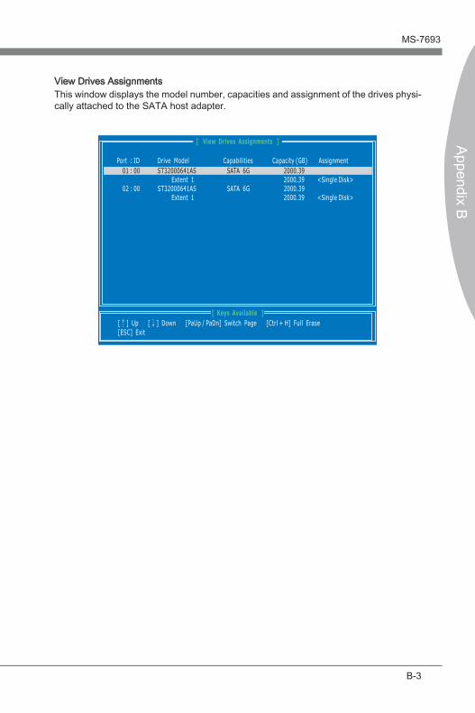
AMD RAID MS-7693
Append�x B
B-3
AMD RAID MS-7693
Append�x B
V�ew Dr�ves Ass�gnments Th�s w�ndow d�splays the model number, capac�t�es and ass�gnment of the dr�ves phys�-cally attached to the SATA host adapter.
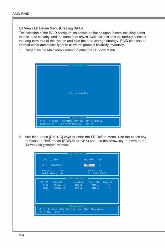
B-4
AMD RAID MS-7693
Append�x B
AMD RAID MS-7693
Append�x B
LD V�ew / LD Define Menu (Creat�ng RAID)The select�on of the RAID configurat�on should be based upon factors �nclud�ng perfor-mance, data secur�ty, and the number of dr�ves ava�lable. It �s best to carefully cons�der the long-term role of the system and plan the data storage strategy. RAID sets can be created e�ther automat�cally, or to allow the greatest flex�b�l�ty, manually.
Press 2 on the Ma�n Menu screen to enter the LD V�ew Menu. 1.
And then press [Ctrl + C] keys to enter the LD Define Menu. Use the space key to choose a RAID mode (RAID 0/ 1/ 10/ 5) and use the arrow key to move to the “Dr�ves Ass�gnments” w�ndow.
2.

AMD RAID MS-7693
Append�x B
B-5
AMD RAID MS-7693
Append�x B
Str�pe Block S�ze, the default 64KB �s best for most appl�cat�ons. RAID 0 or 10 only.G�gabyte Boundary, allows use of sl�ghtly smaller replacement dr�ves.
■
■
On the Dr�ves Ass�gnments w�ndow, use the arrow key to choose the hard dr�ves wh�ch you want to make part of the LD, use the space key to change the ass�gnment to “Y”. Then press [Ctrl+Y] to save the configurat�on.
3.
A message w�ll show, press [Ctrl + Y] to �nput a LD name as your des�re or press any key to save default LD name.
4.
Another message w�ll show, press [Ctrl-Y] �f you are sure to erase the MBR data of the d�sk. Or press any key to �gnore th�s opt�on.
5.

B-6
AMD RAID MS-7693
Append�x B
AMD RAID MS-7693
Append�x B
The message w�ll show up on the bottom, press any key to use max�mum capac�ty or press [Ctrl-Y] to mod�fy array capac�ty manually.
6.
The LD creat�on �s done, the screen shows the LD �nformat�on as below.Press ESC key to the ma�n screen.
7.
ImportantThe default capac�ty �s the full capac�ty of the selected hard dr�ves.If you allocate the first LD capac�ty manually, you can create second LD w�th rema�n-�ng capac�ty of the selected hard dr�ves.
••
Press ESC key to ex�t the ut�l�ty, a message “System �s go�ng to REBOOT! Are You Sure?” w�ll d�splay, answer “Y” to ex�t �t and the system w�ll reboot.
8.

AMD RAID MS-7693
Append�x B
B-7
AMD RAID MS-7693
Append�x B
Delete LD Menu (Delet�ng RAID)Press “3” on the ma�n to enter the Delete LD Menu.Choose a LD No. you want to delete and press [Del] or [Alt+D] delete the RAID set.
1.2.
On the next screen, a message w�ll d�splay to �nform you, press “Ctrl+Y” to delete the RAID set or other key to abort �t. Press “Ctrl+Y” to complete the delet�on.
3.

B-8
AMD RAID MS-7693
Append�x B
AMD RAID MS-7693
Append�x B
Install�ng the RAID Dr�ver (for bootable RAID Array) After you complete the RAID BIOS setup, boot from the W�ndows CD, and the W�n-dows Setup program starts.Press F6 and wa�t for the W�ndows Setup screen to appear.Insert the floppy that conta�ns the RAID dr�ver, press the “S” key to select “Spec�fy Add�t�onal Dev�ce”.
1.
2.3.
When prompted, �nsert the med�um d�sk and press Enter.4.
ImportantPlease follow the �nstruct�on below to make a SATA RAID dr�ver for yourself.
Insert the MSI DVD �nto the DVD-ROM dr�ve.Cl�ck the “Browse CD” on the Setup screen.Copy all the contents �n the : \\Ch�pSet\AMD\Packages\Dr�vers\SBDrv\SB9xx\RAID\ (and then, please select a folder wh�ch was class�fied accord�ng to OS.) The dr�ver d�sk for RAID controller �s done.
•••
•
For W�ndows V�sta/ W�ndows 7: Dur�ng the Operat�ng system �nstallat�on, after select�ng the locat�on to �nstall V�sta/ W�ndows 7 cl�ck on “Load Dr�ver” button to load RAID dr�ve.
You should be shown a l�st of ava�lable RAID controller(s).Select the compat�ble RAID controller for 32-b�t/ 64-b�t vers�on system and then press ENTER. The next screen should confirm that you have selected the RAID controller. Press ENTER aga�n to cont�nue. You have successfully �nstalled the RAID dr�ver, and W�ndows setup should con-t�nue. Leave the med�um unt�l the system reboots �tself. W�ndows setup w�ll need to copy the files from the med�um aga�n after the RAID volume �s formatted, and W�ndows setup starts copy�ng files.
5.6.
7.
8.
9.
Note: for W�ndows V�sta/ W�ndows 7, you can copy the files to a med�um (floppy/ CD/ DVD or USB)

AMD RAID MS-7693
Append�x B
B-9
AMD RAID MS-7693
Append�x B
Install�ng the RAID Dr�ver Under W�ndows (for Non-bootable RAID Array)
Insert the MSI DVD �nto the DVD-ROM dr�ve.The DVD w�ll auto-run and the setup screen w�ll appear.Under the Dr�ver tab, cl�ck on AMD ch�pset dr�vers by your need. The AMD ch�pset dr�vers �ncludes RAID Dr�ver.The dr�ver w�ll be automat�cally �nstalled.
1.2.3.
4.