Embed Size (px)
DESCRIPTION
Guia de Aplicacion Para Potencia Hidraulica
Citation preview

published by
NATIONAL FLUID POWER ASSOCIATION, INC. 3333 N. Mayfair Road / Milwaukee, WI 53222-3219 USA
PHONE: +1 414 778 3344 / FAX: +1 414 778 3361 / E-mail: [email protected]
1 July 2010
Application guidelines for selected fluid power components –
Accumulators
Cylinders Hydraulic valves
Pneumatic filters, regulators and lubricators Selection of position transducers

Copyright 2010 by the NATIONAL FLUID POWER ASSOCIATION
Printed in the USA
All standards, recommended practices, information reports, and bibliographies (collectively, “NFPA Documents”) are advisory only. Use thereof by anyone for any purpose is entirely voluntary and in any event without risk of any nature to the National Fluid Power Association (NFPA), its officers, directors or authors of such work. There is no agreement by or between anyone to adhere to any NFPA Document. In formulating and approving NFPA Documents, NFPA and/or its councils and committees will not investigate or consider citations, references or patents which may or may not apply to such subject matter since prospective users of such NFPA Documents alone are responsible for establishing necessary safeguards in connection with utilization of such matters, including technical data, proprietary rights or patentable materials.
The information and data contained in NFPA Documents has been obtained from sources believed to be reliable. However, it should not be assumed that all acceptable or applicable sources of information, procedures, methods or techniques are contained in NFPA Documents, or that additional measures may not be required under certain circumstances or conditions.
NFPA Documents and/or policies and procedures are subject to periodic review and may be changed without notice. NFPA Documents are only current as of their publication date. NFPA Documents, after publication, may be revised or withdrawn at any time and current information on all NFPA Documents may be received by calling or writing NFPA. Additionally, the various codes and regulations referenced in NFPA Documents may be amended from time to time and it should not be assumed that the versions referenced therein are the most current versions of such codes and regulations. Please consult the appropriate regulatory authorities for the most up-to-date versions.
NFPA Documents imply a consensus of those substantially concerned with their scope and provisions and are intended as a guide to aid the manufacturer, the consumer and the general public. The publication of NFPA Documents does not in any respect preclude anyone, whether they have participated in the development of or approved such NFPA Documents or not, from manufacturing, marketing, purchasing, or using of products, processes or procedures not conforming to the NFPA Documents. NFPA Documents do not constitute or indicate a warranty of any sort, express or implied, including but not limited to a warranty or representation as to quality, merchantability or fitness for a particular use or purpose.
Participation by federal agency representative(s) or person(s) affiliated with the industry is not to be interpreted as government or industry endorsement of an NFPA Document(s).
NOTICE
NFPA Documents do not express or imply any judgment, certification or endorsement of or with respect to, the safety, design or performance of any product, component, or its use.
NFPA does not examine, investigate, test, recommend, or certify the design, use or safety of any product or component, even those which may incorporate one or more NFPA Documents. NFPA Documents therefore have no application to and do not express or imply any recommendation, representation or warranty, with respect to the safety, design, use, performance, or functional interchangeability of components or products which incorporate NFPA Documents.
This publication may not, in whole or in part, be reproduced, copied or disseminated, entered into or stored in a computer database or retrieval system, or otherwise utilized without the prior written permission of NFPA.

Application guidelines – Table of contents
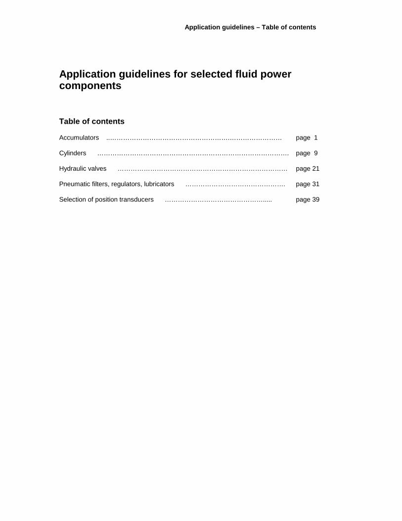
Application guidelines for selected fluid power components
Table of contents
Accumulators ..……………………………………………….…………………… page 1
Cylinders ……………………………………………………………………………. page 9
Hydraulic valves …………………………………………………………………… page 21
Pneumatic filters, regulators, lubricators ………………………………………. page 31
Selection of position transducers ………………………………………..... page 39

Application guidelines - Accumulators
1
Application guidelines – Accumulators
Introduction
In fluid power systems, power is transmitted and controlled through a fluid (liquid or gas) under pressure within an enclosed circuit.
An accumulator is defined as a device for storing hydrostatic energy and subsequently releasing it to do useful work.
The energy can be stored in the form of a compressed spring, lifted weight or compressed gas. By far the compressed gas (which must be an inert gas such as nitrogen) is the most common and is the type discussed in this document. This type is called a hydropneumatic accumulator. This is defined as an accumulator in which compressed gas applies force to the stored liquid.
1 Scope
This recommended practice applies to bladder, diaphragm, and piston types of accumulators for their use in fluid power systems for industrial, marine, and mobile applications.
2 Normative references
The following normative documents contain provisions which, through reference in this text, constitute provisions of the Application guidelines – Accumulators section (pages 1-7) of this NFPA document. For dated references, subsequent amendments to, or revisions of, any of these publications do not apply. However, parties to agreements based on this NFPA document are encouraged to investigate the possibility of applying the most recent editions of the normative documents indicated below. For undated references, the latest edition of the normative document referenced applies. NFPA maintains registers of currently valid NFPA Standards. Standards development organization contact information and links can be found on the NFPA website (www.nfpa.com).
EN 982 (latest edition), Safety of machinery – Safety requirements for fluid power systems and their components – Hydraulics.
ISO 4413 (latest edition), Hydraulic fluid power – General rules relating to systems.
ISO 5598 (latest edition), Fluid power systems and components – Vocabulary.
3 Definitions
For the purposes of this recommended practice, the terms and definitions given in ISO 5598 apply.

Application guidelines - Accumulators
2
4 Accumulator types
The following is a description of commonly used hydropneumatic accumulators. For their official definitions see ISO 5598.
a) A bladder accumulator is an accumulator in which the liquid and gas are separated by an elastic bag or bladder.
b) A diaphragm accumulator is an accumulator in which the liquid and gas are separated by a flexible diaphragm.
c) A piston accumulator is an accumulator in which the liquid and gas are separated by a floating piston.
d) A nonseparator accumulator is an accumulator in which the compressed gas operates directly on liquid within the pressure chamber. This type of an accumulator is not normally recommended because of safety reasons. Standards such as ISO 4413 state that circuits incorporating accumulators shall vent the accumulator liquid pressure or shall positively isolate the accumulator when the equipment is shut off.
5 General
5.1 A hydropneumatic accumulator works by storing energy in the form of a compressed gas. Normally this is an inert gas such as nitrogen. The accumulator is initially charged with some amount of gas pressure (the actual value of this pressure depends on the application); see Figure 1. At some point in the machine cycle, a pump will typically push hydraulic fluid into the hydraulic fluid side of the accumulator. At this point, the separator (a bladder, diaphragm or piston) will compress the gas to the same pressure as the hydraulic fluid; see Figure 2.
Figure 1 – Accumulator empty of hydraulic fluid and containing some amount of gas precharge
Figure 2 – Accumulator charged with hydraulic fluid at maximum system pressure
5.2 When hydraulic fluid flow from the accumulator is required, a valve in the hydraulic system will direct the fluid to the component or components while the expanding gas pushes on the separator, expelling the hydraulic fluid from the accumulator. The pressure of the hydraulic fluid coming from the accumulator will follow the thermodynamic laws as applied to the expanding gas on the other side of the separator. Since the gas volume is not infinite, the hydraulic pressure will drop as an accumulator is discharged; see Figure 3.
As charged
Separator
Gas precharge
Gas pressure
Maximum operating pressure
Separator Hydraulic fluid

Application guidelines - Accumulators
3
NOTE All of the hydraulic fluid has not been expelled. It is considered a good practice to maintain some fluid in the accumulator at the end of the discharge cycle for longer accumulator life.
Figure 3 – Accumulator, after it has been discharged and system is at minimum required system pressure
5.3 The general gas law for expansion or compression of a gas is described by the following equation:
P1 V1n P2 V2
n=
where
P1 is the initial pressure;
V1 is the initial volume;
P2 is the final pressure;
V2 is the final volume;
n is the polytropic exponent.
5.4 If an accumulator is discharged very slowly (this is seldom the case), the polytropic exponent is the isothermal exponent and is equal to 1.0. However, if the discharge is rapid, this value will be closer to the adiabatic exponent and is greater than 1.0. For nitrogen this factor will vary depending on several operating conditions. Consult your accumulator supplier for specific applications. The gas pressure may also vary when an accumulator is charged based on the rate at which it is charged. Again, consult your accumulator supplier for specific applications.
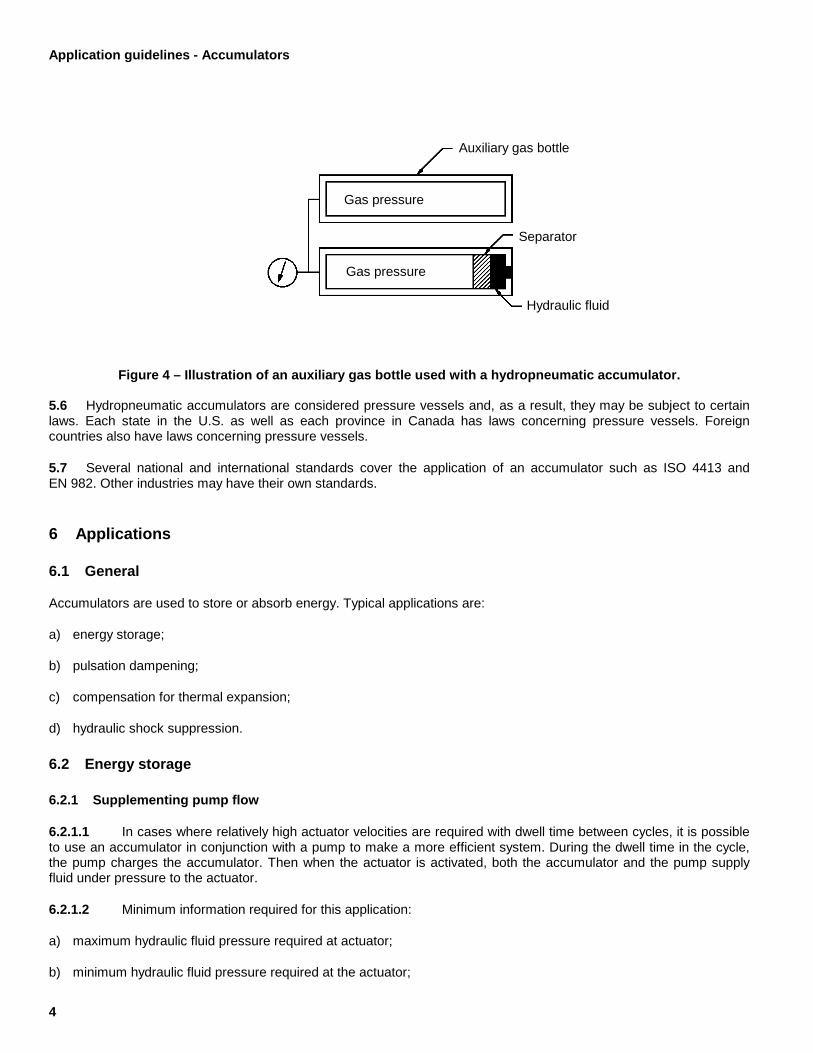
5.5 On occasions, especially when the operation requires the maximum and minimum operating pressures to be close to each other a large amount of gas volume may be required. An auxiliary gas bottle may be used as shown in Figure 4.
Separator Hydraulic fluid
Minimum required system pressure
Gas pressure
Application guidelines - Accumulators
4
Figure 4 – Illustration of an auxiliary gas bottle used with a hydropneumatic accumulator.
5.6 Hydropneumatic accumulators are considered pressure vessels and, as a result, they may be subject to certain laws. Each state in the U.S. as well as each province in Canada has laws concerning pressure vessels. Foreign countries also have laws concerning pressure vessels.
5.7 Several national and international standards cover the application of an accumulator such as ISO 4413 and EN 982. Other industries may have their own standards.
6 Applications
6.1 General
Accumulators are used to store or absorb energy. Typical applications are:
a) energy storage;
b) pulsation dampening;
c) compensation for thermal expansion;
d) hydraulic shock suppression.
6.2 Energy storage
6.2.1 Supplementing pump flow
6.2.1.1 In cases where relatively high actuator velocities are required with dwell time between cycles, it is possible to use an accumulator in conjunction with a pump to make a more efficient system. During the dwell time in the cycle, the pump charges the accumulator. Then when the actuator is activated, both the accumulator and the pump supply fluid under pressure to the actuator.
6.2.1.2 Minimum information required for this application:
a) maximum hydraulic fluid pressure required at actuator;
b) minimum hydraulic fluid pressure required at the actuator;
Auxiliary gas bottle
Gas pressure
Gas pressure
Separator
Hydraulic fluid

Application guidelines - Accumulators
5
c) hydraulic fluid flow rate and volume required by actuator or actuators;
d) pump displacement (volumetric);
e) dwell time.
6.2.2 Leakage compensation
6.2.2.1 Hydraulic valves and cylinder pistons may have some internal leakage. In some applications, it may be desirable to make up this leakage by using an accumulator. This is possible as long as there is some dwell time in the machine cycle so that the pump can recharge the accumulator.
6.2.2.2 Minimum information required for this application:
a) maximum hydraulic fluid pressure required at actuator;
b) minimum hydraulic fluid pressure required at the actuator;
c) expected leakage volume;
d) pump displacement (volumetric);
e) dwell time.
6.2.3 Emergency (auxiliary) power source
6.2.3.1 Certain equipment may require some sort of stored energy to be used in an emergency. In such cases, an accumulator is charged with hydraulic fluid that can be relieved manually or electrically in an emergency.
6.2.3.2 Minimum information required for this application:
a) maximum hydraulic fluid pressure required;
b) minimum hydraulic fluid pressure required at the actuator;
c) hydraulic fluid flow rate and volume required by actuator or actuators.
6.3 Pulsation dampening
6.3.1 Positive displacement pumps, especially piston type, generate hydraulic flow that may exhibit pressure ripple, which is not always desirable. The exact amount of ripple depends on pump displacement, pressure and number of pumping chambers. Accumulators can be used to smooth out these pressure ripples.
6.3.2 Minimum information required for this application:
a) pump displacement (volumetric);
b) number of pumping chambers in pump;
c) rotational speed of pump;
d) system pressure.

Application guidelines - Accumulators
6
6.4 Compensation for thermal expansion
6.4.1 Thermal expansion, if not compensated for in a closed loop hydraulic system, can increase pressure beyond acceptable limits. Accumulators absorb the volume increase and return fluid to the line when the temperature falls.
6.4.2 Minimum information required for this application:
a) type of hydraulic fluid;
b) fluid conductor material;
c) volume of contained fluid;
d) normal operating temperature;
e) maximum operating temperature;
f) normal operating pressure;
g) maximum operating pressure.
6.5 Hydraulic shock suppression
6.5.1 When valves open and close quickly, they can generate shock waves in a hydraulic system. Both shock and vibration can generate noise and also lead to premature wear and tear on machine components. Accumulators have relatively good damping characteristics over a wide frequency range that effectively reduces shock and vibration.
6.5.2 Minimum information required for this application:
a) flow rate in hydraulic lines;
b) specific gravity of hydraulic fluid;
c) length and size of hydraulic lines;
d) valve closing time;
e) operating pressure;
f) maximum operating pressure.
7 Ports
It is suggested that the port at the hydraulic end of the accumulator be of a type that is sealed by an elastomer rather than an interference fit, such as a pipe thread port. It is also suggested that the port size be sufficiently large for the required fluid flow rate out of the accumulator.
8 Environment
Accumulators contain static seals as well as dynamic seals in the separator. These seals, which are available in several compounds, are exposed to the operating condition of the accumulator as well as the hydraulic fluid. Seal selection

Application guidelines - Accumulators
7
should be done together with the accumulator manufacturer, taking into account the maximum and minimum operating temperature and hydraulic fluid used.
9 Corrosion
Accumulators are considered pressure vessels. As a result, corrosion, both internal and external, should be taken into account. Internal corrosion that can be caused by the hydraulic fluid will both weaken the pressure vessel and damage the separator. External corrosion will weaken the pressure vessel. Therefore, the environment to which the accumulator is exposed must be considered. Some codes also require that a corrosion allowance be addressed in the stress calculations related to the pressure vessels.
10 Mountings
An accumulator should be securely mounted to a machine frame. The hydraulic plumbing should not be the sole method by which the accumulator is secured to a machine frame. Care should be taken not to squeeze the body of piston accumulators by overtightening U-bolt type brackets. Your accumulator supplier should be consulted for the proper method of securing the accumulator to the machine frame, as well as its orientation.
11 Precharge pressure
11.1 Each specific application shall be accomplished most effectively with a specific value of precharge pressure. The specific value shall be determined by the system operating conditions. Variation from this pressure will cause the system to degrade in performance. Since the precharge pressure is gas pressure in a contained vessel, it will vary as a function of temperature, i.e., if the gas temperature increases, the pressure will increase, and if the gas temperature decreases, the pressure will decrease.
11.2 In a typical hydraulic system, the operating temperature of the accumulator is usually higher than the temperature of the surrounding environment. When checking the precharge pressure, it is important to determine the temperature of the gas. It is easiest to check the pressure when the equipment has been shut down for some time and the gas temperature has stabilized to the temperature of the surrounding environment. Also, shutting down the equipment may remove all hydraulic fluid from the accumulator, which will affect the gas precharge pressure value. Therefore, it is important to know how the precharge pressure in this condition will translate to a gas pressure at operating conditions. The accumulator supplier can help to determine these two values.
12 Maintenance
12.1 An accumulator should be charged only with an inert gas, such as nitrogen.
12.2 Charging of an accumulator or the periodic checking of proper precharge pressure should be done only in accordance with the accumulator manufacturer’s instructions and using only components specified by the accumulator manufacturer.
12.3 Any repair to an accumulator shall be done after it has been relieved of liquid and gas precharge pressure and removed from the hydraulic system. The discharging, removal and repair shall be done by a properly trained person following procedures specified by the accumulator manufacturer.


Application guidelines - Cylinders
9
Application guidelines – Cylinders
Introduction
In fluid power systems, power is transmitted and controlled though a fluid under pressure within an enclosed circuit. The application of hydraulic and pneumatic cylinders requires precise communication between manufacturer and user. It is the intent of this recommended practice to provide basic guidance in cylinder applications and to promote communication. Users of this recommended practice are cautioned, however, to review each clause for applicability and to utilize sound engineering judgement
1 Scope
This recommended practice will apply to hydraulic and pneumatic fluid power cylinders for their use in hydraulic and pneumatic systems for industrial, marine, and mobile applications.
2 Normative references
The following standards contain provisions which, through reference in this text, constitute provisions of the Application guidelines – Cylinders section (pages 9-20) of this NFPA document. At the time of publication, the editions indicated were valid. All documents are subject to revision, and parties to agreements based on this NFPA document are encouraged to investigate the possibility of applying the most recent editions of the documents indicated below. NFPA maintains registers of currently valid NFPA standards.
NFPA/T3.6.7 R1-1996, Fluid power systems and products — Square head industrial cylinders — Mounting dimensions.
ISO 5598:1985, Fluid power systems and components — Vocabulary.
3 Definitions
A description of different types of cylinders is given in this document several times. For their official definition as well as definition of other terms see ISO 5598.
4 Operation and cylinder concepts
Cylinders are used when linear force and motion are required. Cylinders are broken down into two main categories: pneumatic and hydraulic. Pneumatic cylinders can be operated by several types of gases, however, compressed air is by far the most common. Hydraulic cylinders can be operated with a very large range of fluids. By far the most common is petroleum based hydraulic fluid. Fire-resistant fluids are also common, they may be synthetic or water based.

Application guidelines - Cylinders
10
Cylinders can be broken down into two main components. The pressure containing envelope and the piston and rod assembly. Typically the pressure containing envelope is fixed on the machine and the piston and rod assembly is attached to the machine member on which motion and force need to be applied. In rare occasions the opposite is done. See figure 1.
Figure 1 — Typical cylinder
4.1 Force.
The amount of force applied to the machine member is the product of the fluid pressure multiplied by the effective area of the piston. Most cylinders contain a single piston rod. Assuming a constant value for the applied pressure, a cylinder would normally exert more force in the push stroke than it will in the retract stroke. The amount by which the retract force is less than the extend force depends on the cross-sectional area taken up by the piston rod. See figure 2.
For example, a 100 mm bore (10 cm) cylinder housing a 45 mm (4.5 cm) diameter piston rod operating at 1,000 kilopascals (1,000 kPa) will deliver 7,854 neutons (N) of force in the push direction and 6,264 N in the pull direction. Example: one neuton (N) of force = one pascal (Pa) applied to an area one meter square (M2). N=Pa M2
Calculation for push stroke surface area = Π4 D2 bore
Calculation for pull stroke surface area = Π4 (D2 bore - D2 rod)
An area of 78.54 cm2 = 0.007854 M2
In push direction force (N) = 1,000 kPa x 0.007854 M2=7,854 neutons
In pull direction force (N) = 1,000 kPa x 0.006264 M2=6,264 neutons
F pull F push
Piston and Rod assembly
Pressure containing envelope
Motion

Application guidelines - Cylinders
11
Figure 2 — Effective areas
4.2 Velocity
The velocity at which the piston and rod assembly moves is dependent on the rate at which the fluid is introduced into the cylinder. Normally a cylinder is connected to a directional valve and sometimes flow control valves. In a pneumatic system the maximum speed of the piston and rod assembly is dependent on the rate at which the air can flow through the valving. For a hydraulic cylinder, the maximum piston rod velocity depends on the ability of the hydraulic system to provide the hydraulic fluid to the cylinder. In most applications piston rod velocity is held in the .3 to .9 m/s. However, velocities up to 3 m/s have been achieved. See figure 3.
10 cm Dia piston
4.5 cm Dia. Piston rod Area = 78.54 cm2
Area = 62.64 cm2

Application guidelines - Cylinders
12
Figure 3 — Hydraulic and pneumatic circuits
5 Basic construction
The following three types of construction are the more commonly used types of cylinders.
5.1 Square head tie rod
This is a very common type of cylinder used in industrial applications. Head and cap enclosures are secured by tie rods that run the length of the cylinder. See figure 4.
Hydraulic circuit
Pneumatic circuit

Application guidelines - Cylinders
13
Figure 4 — Square head tie rod cylinder
5.2 Bolted end
These cylinders have flanges that are attached to the barrel. The end caps are attached to these flanges with bolts. See figure 5.
Figure 5 — Bolted end
5.3 Nonbolted end
This type of cylinder has end caps that are usually retained by welding or with a locking ring. In many cases these are used for mobile applications. Some pneumatic cylinders crimp the tube onto the end caps. See figure 6.
Figure 6 — Nonbolted end
6 Types of cylinders
Double acting, single piston rod cylinders are by far the most common types of hydraulic and pneumatic cylinders used in industry. However, there are other configurations which are used in special situations.
6.1 Double acting
By far, most cylinders are considered double acting. That is, when the cylinder is required to extend, pressure is applied to the cap end of the cylinder while pressure is exhausted from the rod end. When the cylinder is required to retract, pressure is applied to the rod end and the cap end is exhausted. See figure 7.

Application guidelines - Cylinders
14
Figure 7 — Double acting
6.2 Single acting
In these types of cylinders pressure is applied only to one side of the piston, and some other force is used to move the piston and rod assembly in the opposite direction. In some cases it may be gravity; however, in most cases this is accomplished by a spring. Springs can be mounted on either side of the piston. However, most commonly a spring is mounted on the rod end of the piston and is used to retract the cylinder. Springs can be mounted in either hydraulic or pneumatic cylinders. Normally the mechanical force provided by a spring is rather small in comparison to the potential force which a hydraulic cylinder can apply. Therefore, most single acting cylinders tend to be pneumatic. See figure 8.
Figure 8 — Single acting
6.3 Double rod
Double rod cylinders can be used so that the applied load to the machine member is the same in both directions. Sometimes a smaller rod is used on one end to trip limit switches. See figure 9.
Figure 9 — Double rod end
6.4 Ram cylinders
The rod and piston are the same diameter. This type of cylinder is usually single acting, with an external force used to retact the cylinder. A typical application is a lift in a service station. See figure 10.
Fluid flow
Spring
Fluid flow
Fluid flow
Fluid flow
Thrust Thrust
Fluid flow

Application guidelines - Cylinders
15
Figure 10 — Ram
6.5 Telescopic cylinders
Telescopic cylinders utilize multiple sections to achieve long strokes when short collapsed lengths are required. This type of configuration is sometimes used in cylinders for dump trucks or lift trucks. These are usually single acting. The net force is a function of the smallest section. See figure 11.
Figure 11 — Telescopic
6.6 Tandem cylinders
Tandem cylinders consist of two pistons attached to a common piston rod. These cylinders are used in situations where space requirements are very tight and the combined areas of two pistons can be applied to one piston rod. These are used to increase force. In some cases such as a press, a tandem cylinder is constructed of a large press cylinder with a small cylinder attached to the back. This configuration is used where the smaller bore cylinder is pressurized to rapidly advance the larger cylinder. See figure 12.
Figure 12 — Tandem
6.7 Duplex cylinders
Duplex cylinders consist of multiple piston and rod assemblies which are not connected to each other. This configuration is often used where more than two distinct stopping points are required. See figure 13.
Figure 13 — Duplex
6.8 Rodless cylinders
These cylinders are typically used when limited space prohibits the use of a cylinder with a piston rod.
or

Application guidelines - Cylinders
16
6.8.1 Direct coupled
The carriage and piston are directly connected. See figure 14 .
Figure 14 — Direct coupled
6.8.2 Magnetically coupled
The carriage is and piston are magnetically coupled. See figure 15.
Figure 15 — Magnetically coupled
6.8.3 Cable connected
The carriage is connected to the piston by a cable or flexible band. See figure 16.
Figure 16 — Cable connected
Carriage
Piston
Carriage
Piston
Carriage
Piston
Motion
Fluid flow
Fluid flow
Cable/band
Application guidelines - Cylinders
17
7 Mounting
7.1 Fixed and pivot
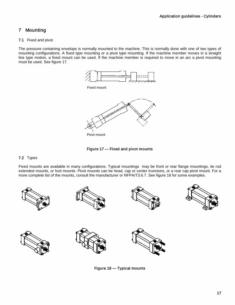
The pressure containing envelope is normally mounted to the machine. This is normally done with one of two types of mounting configurations. A fixed type mounting or a pivot type mounting. If the machine member moves in a straight line type motion, a fixed mount can be used. If the machine member is required to move in an arc a pivot mounting must be used. See figure 17.
Figure 17 — Fixed and pivot mounts
7.2 Types
Fixed mounts are available in many configurations. Typical mountings may be front or rear flange mountings, tie rod extended mounts, or foot mounts. Pivot mounts can be head, cap or center trunnions, or a rear cap pivot mount. For a more complete list of the mounts, consult the manufacturer or NFPA/T3.6.7. See figure 18 for some examples.
Figure 18 — Typical mounts
Fixed mount
Pivot mount

Application guidelines - Cylinders
18
7.3 Mounting enhancements
Selection of any mounting style depends primarily upon the operating specifications of the application. Cylinder mounting directly affects the maximum operating pressure at which the cylinder may be used. Whether the cylinder is used in thrust (push) or tension (pull), its stroke length, piston rod diameter and method of connection to the load must be considered when selecting a mounting style.
Fixed mountings that absorb the force on the centerline of the cylinder are considered the best for straight line force transfer. The symmetrical mountings allow the thrust or tension forces to be distributed uniformly within the mounting framework. Flange mounts are considered the best mounting styles within this category. Front flange mounts are ideally suited when the piston rod is in tension (pull), while cap flanges are recommended for thrust (push) applications.
Fixed noncenterline mountings do not absorb forces on their centerline. The offset thrust introduces bending stresses and additional loads on the mounting bolts. This is especially true in short stroke applications. This type should be very well aligned for maximum service life. Use of shear pins or keys should be considered when these cylinders are subjected to high pressures or shock loads. These mountings are among the easiest to use for mounting and replacement ease.
If the path of the load is curved or misalignment is a problem, a pivoted centerline mounting should be used. These mounts offer compensation for non-linear travel in only one plane. Pivot mounts require a pivot type rod attachment.
Threaded rod end attachments should be torqued tightly against a threaded shoulder to minimize bending and reduce fatigue stresses.
8 Design considerations
8.1 Column strength
Piston rod column failure (buckling) can occur if the rod diameter is not sized to match the stroke and load. The manufacturer should be consulted for application assistance. Reference figure 19 for an example of piston rod column failure.
Figure 19 — Piston rod column failure
8.2 Bearing load
Cylinders are normally intended to push and pull without excessive side load. If a side load exists, the manufacturer should be consulted. Usually bearing load can be reduced with the addition of a stop tube. The use of a stop tube increases the distance between the piston bearing and piston rod bearing. See figure 20.
Figure 20 — Stop tube
Piston bearing Stop tube
Piston rod bearing

Application guidelines - Cylinders
19
8.3 Cushions
The purpose of a cushion is to decelerate the piston and rod assembly as it nears the end of stroke, preventing excessive mechanical stresses. Cushions may be of either a fixed or adjustable design. Both designs function by providing a bypass passage to remove the pressurized fluid trapped between the piston and the cylinder head when the cushion sleeve has entered the cushion bore. Varying the orifice opening with an adjustable cushion screw allows the user to select the best cushion rate for the system. A check valve in the cushion assembly allows for the free flow of fluid back to the piston face for quick acceleration when the rod is withdrawn. Heavy loads may also require an external device to stop the motion. Cushions are available on either or both ends of the cylinder. Consult manufacturer for the conditions under which cushions should be used. See figure 21.
Figure 21 — Cushions
8.4 Eccentric Loads
A very important general consideration is to keep the cylinder thrust as close as possible to the centerline of the piston rod and free from misalignment or side thrust. Off-center thrust or side loads can substantially reduce the service life expected from the rod bearing and seals. Off-center thrust and side loading can be caused by cylinder deflection under load, machine frame deflection, rod bending or sagging, as well as by poor design of the machine. See figure 22.
Figure 22 — Eccentric Loads
9 Compatibility
The temperature and fluid type must be considered in any application to ensure proper seal effectiveness and life. The manufacturer should be consulted for assistance.
10 Corrosion
Surfaces of either hydraulic or pneumatic cylinders can be corroded by water or other substances. Although paint may be suitable protection against corrosion for most indoor industrial uses, the cylinder specifier should be aware of corrosion potential in the operating environment. The material content and surface preparation of the piston rod must be considered in any application where a corrosive environment exists. Consult the cylinder manufacturer for corrosion protection recommendations.
Piston rod motion
Piston rod centerline
Applied load
Fluid flow
Application guidelines - Cylinders
20
11 Maintenance
Cylinder maintenance primarily involves replacing seals and/or bearings. Consult the manufacturer for maintenance guidelines.
11.1 Visual inspection
Degradation of cylinder thrust or erratic motion can indicate seal leakage. Prior to disassembly, visual inspection can be performed on the rod seal and tube end seals. This is accomplished by inspecting these locations for either oil or escaping air depending on whether the cylinder is hydraulic or pneumatic. Inspection of the piston seals and bearing require disassembly.
11.2 Disassembly
Prior to performing any maintenance that requires the disassembly of the cylinder, the pressure within the cylinder must be zero. The machine manufacturer should be consulted for any lock-out requirements.
Follow the cylinder manufacture’s recommended disassembly and reassembly procedures, paying particular attention to prescribed fastener torque values and internal springs. While the cylinder is disassembled, inspect all components for evidence of unusual wear. Signs of internal corrosion may indicate the presence of water or lack of lubrication. Signs of contamination may indicate improper filtration. Proper preventative maintenance will extend seal and bearing life. Wear can be caused by misalignment of the cylinder and load, or other problems that should be remedied before the cylinder is returned to service.
11.3 Preventative maintenance.
Preventative maintenance such as hydraulic oil filtration and compressed air filtration/drying will extend cylinder service intervals.

Application guidelines - Hydraulic valves
21
Application guidelines — Hydraulic valves
Introduction
In hydraulic fluid power systems, power is transmitted and controlled through a liquid under pressure within an enclosed circuit. The application of hydraulic valves requires precise communication between manufacturer and user. It is the intent of this recommended practice to provide basic guidance in valve application and to promote communication. Users of this recommended practice are cautioned, however, to review each section for applicability and to utilize sound engineering judgment.
1 Scope
1.1 This recommended practice is applicable to hydraulic valves used in industrial, marine and mobile equipment.
1.2 This recommended practice provides basic guidance for the selection, installation, operation, and maintenance of hydraulic valves.
2 Normative references
The following normative documents contain provisions which, through reference in this text, constitute provisions of the Application guidelines -- Hydraulic valves section (pages 21-29) of this document. For dated references, subsequent amendments to, or revisions of, any of these publications do not apply. However, parties to agreements based on this NFPA document are encouraged to investigate the possibility of applying the most recent editions of the normative documents indicated below. For undated references, the latest edition of the normative document referenced applies. NFPA maintains registers of currently valid NFPA Standards. Standards development organization contact information and links can be found on the NFPA website (www.nfpa.com).
NFPA/T2.6.1 R2-2001 (R2005), Fluid power components – Method for verifying the fatigue and establishing the burst pressure ratings of the pressure containing envelope of a metal fluid power component
NFPA/T2.24.2 (latest edition), Hydraulic fluid power systems — Methods for preventing external leakage.
NFPA/T3.5.1 (latest edition), Hydraulic fluid power — Valves – Mounting surfaces.
NFPA/T3.5.14 (latest edition), Hydraulic fluid power — Directional control valves — Method for determining the metering characteristics.
NFPA/T3.5.15 (latest edition), Hydraulic fluid power — Valves — Method for determining the internal leakage characteristics.
NFPA/T3.5.16 (latest edition), Hydraulic fluid power — Flow control valves — Method for measuring and reporting regulating characteristics.
NFPA/T3.5.26 R2-2000 (R2005), Hydraulic valve – Pressure rating supplement to NFPA/T2.6.1 R2-2000 – Method for verifying the fatigue and burst pressure ratings of the pressure containing envelope of a metal fluid power hydraulic valve

Application guidelines - Hydraulic valves
22
IEEE/ASTM SI 10 (latest edition), Standard for Use of the International System of Units (SI): The Modern Metric System.
ISO 1000 (latest edition), SI units and recommendations for the use of their multiples and of certain other units.
ISO 1219-1 (latest edition), Fluid power systems and components – Graphic symbols and circuit diagrams – Part 1: Graphic symbols for conventional use and data processing applications (second edition)
ISO 1219-2 (latest edition), Fluid power systems and components – Graphic symbols and circuit diagrams – Part 2: Circuit diagrams
ISO 4401 (latest edition), Hydraulic fluid power — Four-port directional control valves – Mounting surfaces.
ISO 4406 (latest edition), Hydraulic fluid power — Fluids — Method for coding level of contamination by solid particles.
ISO 5598 (latest edition), Fluid power systems and components — Vocabulary.
ISO 6149-1 (latest edition), Connections for hydraulic fluid power and general use – Ports and stud ends with ISO 261 metric threads and O-ring sealing – Part 1: Port with truncated housing for O-ring seal (second edition)
ISO 6149-2 (latest edition), Connections for hydraulic fluid power and general use – Ports and stud ends with ISO 261 threads and O-ring sealing – Part 2: Dimensions, design, test methods and requirements for heavy-duty (S series) stud ends (second edition)
ISO 6149-3 (latest edition), Connections for hydraluic fluid power and general use – Ports and stud ends with ISO 261 threads and O-ring sealing – Part 3: Dimensions, design, test methods and requirements for light-duty (L series) stud ends (second edition)
ISO 6162-1 (latest edition), Hydraulic fluid power – Flange connectors with split or one-piece flange clamps and metric or inch screws – Part 1: Flange connectors for use at pressures of 3,5 MPa (35 bar) to 35 MPa (350 bar), DN 13 to DN 127
ISO 6162-2 (latest edition), Hydraulic fluid power – Flange connectors with split or one-piece flange clamps and metric or inch screws – Part 2: Flange connectors for use at pressures of 35 MPa (350 bar) to 40 MPa (400 bar), DN 13 to DN 51
ISO 7368 (latest edition), Hydraulic fluid power — Two-port slip-in cartridge valves – Cavities.
ISO 10770-1 (latest edition), Hydraulic fluid power — Electrically modulated hydraulic control valves — Part 1: Test methods for four-way directional flow control valves.
ISO 11926-1 (latest edition), Connections for general use and fluid power – Ports and stud ends with ISO 725 threads and O-ring sealing – Part 1: Ports with O-ring seal in truncated housing
ISO 11926-2 (latest edition), Connections for general use and fluid power – Ports and stud ends with ISO 725 threads and O-ring sealing – Part 2: Heavy-duty (S series) stud ends
ISO 11926-3 (latest edition), Connections for general use and fluid power – Ports and stud ends with ISO 725 threads and O-ring sealing – Part 3: Light-duty (L series) stud ends
SAE J518 (latest edition), Hydraulic flanged tube, pipe, and hose connections, 4 bolt split flange type.
SAE J1783 (latest edition), Selection of hydraulic directional control valves for marine vehicle applications.
Application guidelines - Hydraulic valves
23
3 Terms and definitions
For the purposes of this NFPA document, the terms and definitions given in ISO 5598 apply.
4 General
4.1 Valve classifications
Hydraulic valves can be classified into four general categories based on their function. These categories are described in 4.1.1 through 4.1.4.
Valve assemblies or subassemblies comprise components from more than one valve category, such as a directional valve incorporating an internal pressure control valve. See ISO 1219-1 and ISO 1219-2 for hydraulic valve graphic symbols and their use in circuit diagrams.
4.1.1 Directional control valves
Directional control valves connect or isolate one or more flow paths. They are commonly used to control speed and direction of a hydraulic actuator. They may range from a simple two-port check valve to a multiple-port directional valve. Application guidelines for these valves are contained in clause 5.
4.1.2 Pressure control valves
Pressure control valves are commonly used to limit or control pressure excursions of the pump or of portions of the hydraulic circuit. They may range from direct-acting relief valves to pilot-operated counterbalance valves. Application guidelines for these valves are contained in clause 6.
4.1.3 Flow control valves
Flow control valves are used to limit or control flow with the circuit or portions of the circuit. They may range from a simple fixed orifice to a pressure- and temperature-compensated flow control valve. Application guidelines for these valves are contained in clause 7.
4.1.4 Load holding valves
Load holding valves are used to prevent drift of a loaded actuator and to prevent uncontrolled movement of an actuator due to overrunning loads. Application guidelines for these devices are contained in clause 8.
4.2 Fluids
Hydraulic fluids may range from petroleum oils to synthetics, fire resistant fluids and biodegradable fluids. Select a fluid that is appropriate for the system and machine type and environment.
Fluid types and equipment manufacturer’s recommendations may vary widely among mobile, industrial, and marine systems. Ensure that valves, including seals and electrical wiring, are compatible with the system fluid.
4.3 Fluid conditioning
Fluid filtration requirements depend upon several factors, including the type of system and components, the severity of the application, the operating environment, and the level and frequency of maintenance. Filtration should be provided to maintain the system fluid within the cleanliness level recommended by the valve manufacturer and system designer.
The system design and installation should minimize entrained air and other contaminants, such as water. The fluid temperature and water content should be maintained at levels consistent with the fluid and component manufacturer’s recommendations. Acceptable fluid temperature ranges will differ among mobile, industrial, and marine systems.

Application guidelines - Hydraulic valves
24
4.4 Ports
Valve ports should be of the O-ring sealed straight thread type conforming to ISO 6149-1 or ISO 11926-1, or of the flange type conforming to ISO 6162-1, ISO 6162-2 or SAE J518. Ports with pipe threads should not be used because of the potential for external leakage. See also NFPA/T2.24.2 for additional information on port types and their characteristics.
4.5 Mounting
Valves are available in many different construction and mounting configurations, including:
a) independently mounted, of monoblock, sectional, or combination block construction
b) subplate or manifold mounted, in accordance with ISO 4401, NFPA/T3.5.1, or custom interface design
c) cartridge design and installation, of the screw-in type in accordance with ISO 7789 or NFPA/T3.5.50, or of other custom design.
d) cartridge design and installation, of the slip-in type in accordance with ISO 7368, or of other custom design
e) actuator installed or direct mounted
The function or at rest mode of some valves may be influenced by the mounting direction. Consult the manufacturer for recommendations regarding preferred mounting.
4.6 Location
In most cases, valves should be mounted as close to the actuators as practical. Valves should also be installed so that they are accessible for maintenance and removal. In the case of manual valves, ease of actuation shall be taken into account.
4.7 Pressure rating and reliability
Valve selection should take into account the maximum pressure excursions in the system, the operating duty cycle, and the expected service life. The potential for overloads, external mechanical loads, and other abnormal conditions should be considered. Fatigue rating of the pressure containing envelope(s) of valves should be in accordance with NFPA/T2.6.1 and NFPA/T3.5.26.
4.8 Repair and maintenance
Specific instructions for maintenance and repair should be contained in the equipment manual(s) and/or on equipment decals. If a repair involves disassembly of a valve or its hydraulic connections, care shall be taken to ensure that the cleanliness levels recommended in 4.3 are maintained before the valve is returned to service. Replacement fluid shall be of the proper type and shall meet the cleanliness requirements of 4.3.
4.9 Other application considerations
Other system and application characteristics that may affect the performance or reliability of valves include:
a) excessive vibration or shock, particularly if valves are cantilever mounted or if the system could be unstable under certain conditions;
b) intermittent temperature extremes, such as cold startup conditions or temporary overheating;
c) exposure to unusual or extreme environments, such as water spray or immersion, corrosive chemicals, fine dust, abrasive materials, etc. See SAE J1783 for marine application guidance;
d) hazardous locations that may require explosion-proof or intrinsically safe devices.

Application guidelines - Hydraulic valves
25
5 Directional control valve application guidelines
5.1 Check (non-return) valves
Unpiloted two-port check (non-return) valves are one of the simplest forms of directional control valves, blocking flow in one direction and allowing essentially free flow or flow at a prescribed pressure in the opposite direction. The check valve shall be sized to provide an acceptable pressure drop at maximum flow and shall be designed to provide acceptable internal leakage control in the blocking condition. Check valves normally are spring-biased to assist in rapid closing, stability, and leakage control. The spring bias adds to the pressure drop in the open condition.
Three-port check valves, also known as shuttle valves, are utilized to connect the higher or lower pressure of two lines to a third connection. Pilot-to-open and pilot-to-close check valves are also available for situations in which the check valve must respond to an external pilot pressure. See clause 8 for a more detailed discussion of load holding valves.
5.2 Directional control valves
Directional control valves may be actuated mechanically, hydraulically, pneumatically or electrically. Electrical actuation can be on/off or proportional. In the case of hydraulically, pneumatically or electrically piloted valves, the pilot system shall be designed to provide satisfactory response and acceptable characteristics in the event of failure. Directional control valves are normally spring-centered but may also contain mechanical detents, electromagnetic detents or other devices. Valves shall be sized to provide acceptable pressure drops at maximum flow rates, recognizing that individual ports may have different flow rates. If the internal leakage characteristics of the directional control valve are such that actuator creep is a concern, the use of pilot-operated check valves or other blocking valves should be considered.
5.2.1 Two-port valves
Two-port spool, poppet, gate, or other mechanical valves are used to connect or disconnect two-ports. They differ from check valves in that they are typically bidirectional when open. Internal leakage characteristics may differ from check valves, depending upon the design.
5.2.2 Three-port valves
Three-way valves provide a means to connect and disconnect three ports. A typical application of a two-position, three-port valve is to bypass pump flow to tank in one position and to connect pump flow to an actuator in the other.
5.2.3 Four-port valves
Four-port valves provide a means to connect and disconnect four ports. A two-position, four-port valve can be used to control an actuator in forward and reverse directions by connecting opposite actuator ports to pump flow or to tank. Intermediate or transition characteristics of the valve may have a significant impact on pump and actuator pressures and metering, and should be selected based on the requirements of the application.
Four-port valves are often applied in a three-position configuration, with the third (center) position providing a neutral condition for the pump and a holding or freewheeling condition for the actuator. A holding or blocked actuator port, center position is normally used with cylinders in order to maintain a load in position. The valve shall have internal leakage characteristics that result in acceptable drift rates for the loaded cylinder. A freewheeling, or vented-to-reservoir actuator port, center position is normally used with motors in order to allow the motor to coast to a stop after pump inlet flow is disconnected, avoiding large pressure spikes. With regard to the pump, the three-position valve can be open center, in which the pump flow is bypassed to the reservoir, or closed center, in which the pump flow path is blocked. An open center valve is normally used with a fixed displacement pump, and a closed center valve is typically selected for use with a variable displacement pump or a fixed displacement pump with an integral unloading device. Closed center valves may also be load sensing, controlling a pressure and flow compensated pump’s displacement by means of a sensing line downstream of the valve’s metering element.
Special four-position options are also available with four-port valves. A relatively common fourth position option with cylinders is float, in which both sides of the cylinder are connected to the reservoir (unlike the center, or holding, position in which both ports are blocked). Regeneration, in which the supply side of the cylinder is connected to both the pump and the return (rod) side of the cylinder, is another option. This provides faster cylinder speed, but at the expense of available force, since the pressure is effectively only acting on the rod area of the cylinder.

Application guidelines - Hydraulic valves
26
5.2.4 Circuit types
Multi-function directional valve circuits may be of the parallel, series parallel, or series type. In a parallel circuit, the individual control spools are connected to the valve inlet by a common passage, so that any one of the spools can receive flow from the pump, or all spools can receive flow simultaneously. However, unless the valve is closed center and has some means of pressure compensation, the function with the lowest load pressure will receive the flow. Series parallel (sometimes called conventional) circuits are similar to parallel circuits except that the first spool receives all of the flow if it is fully stroked. These circuits are utilized when it is desired to give one function priority over all of the others. Series circuits connect the work port return flow from an upstream function to the inlet of the adjacent downstream function, thereby ensuring simultaneous operation capability of two or more functions. However, the load pressures of individual functions are additive in series circuits. The actuators shall be sized appropriately to move the desired loads at less-than-full pump pressure.
Open center directional valves may also incorporate a feature known as power beyond (sometimes called high pressure carryover), which directs pump flow to a port that can be used to supply another downstream valve. Flow is available at the power beyond port if all of the valve spools are in their neutral positions, but if any one of the valve spools is fully stroked, flow to the power beyond port is cut off.
5.2.5 Proportional valves and servovalves
Electrohydraulic proportional valves and servovalves offer more sophisticated directional control options, but may require more care in their proper selection and application. Servovalves are normally higher cost, but may be distinguished from proportional valves by their improved performance in terms of dynamic response, hysteresis, repeatability, and threshold. Improvements in proportional valve frequency response have reduced the distinction between proportional and servovalves based on this parameter. Manufacturer’s literature should be consulted for specific data.
Probably the most common physical differentiator between proportional valves and servovalves is their spool center or lap conditions. Servovalves are critically lapped by carefully matching the width and position of the spool lands to the appropriate metering lands within the body. Proportional valve spools and bodies typically lack this matching, resulting in a center overlap, and a corresponding flow deadband of up to 3% of the valving element stroke.
Proportional valves may be direct-operated or pilot-operated, and they may or may not have an internal feedback loop. Servovalves are two-stage devices, with the first stage most commonly of the flapper nozzle, jet pipe, or jet diverter design. Due to the relatively small orifices or clearances in these designs, servovalves normally require that they be used in a system with finer filtration than do proportional valves.
6 Pressure control valve application guidelines
6.1 Direct-acting relief valves
Direct-acting relief valves are normally closed devices biased to the closed position by a spring. They are rapid opening devices that can be produced in low internal leakage designs, making them suitable for shock limiting and structure protecting applications. Back pressure in the outlet line is additive to the spring setting. Direct-acting relief valves may exhibit considerable rise in pressure from initial opening to full opening. They will act as a fixed orifice when fully open, so care shall be taken to avoid exceeding their rated flow. Poppet or differential area type direct-acting relief valves are generally more tolerant of contamination.
6.2 Pilot-operated relief valves
Pilot-operated relief valves are normally closed devices biased to the closed position by a spring and by pilot pressure. They typically do not open as quickly as direct-acting relief valves, but their flow capacity is much greater in the same package size. Back pressure in the outlet line is additive to the spring setting. Pilot-operated relief valves also normally have lower pressure increase from initial opening to the full open position but have greater internal leakage. They are suited to system relief applications for pump and circuit pressure protection.

Application guidelines - Hydraulic valves
27
6.3 Sequence valves
Sequence valves are normally closed devices that differ from standard relief valves in that the outlet flow is directed to another pressurized function rather than to the reservoir when the valve opens. Since outlet flow is pressurized, they require an externally drained spring or pilot cavity. Sequence valves are utilized to ensure that one operation occurs before a second begins.
6.4 Unloading valves
Unloading valves are normally closed devices that are controlled by a sensing line from the main circuit. They are often used to bypass the flow from a fixed displacement pump to the reservoir at low pressure when no functions are operating and to bypass excess flow to the reservoir at a small margin above load pressure when one or more functions are operating at flows less than full pump capacity. The unloading valve is spring biased to produce a preset margin pressure above sensing line pressure. Unloading valves are also often used in circuits with accumulators to reduce pump pressure when the accumulator is adequately charged.
6.5 Pressure-reducing valves
Generally, pressure-reducing valves are normally open devices that close to restrict or block flow from the main circuit to a secondary circuit, thereby maintaining a relatively constant reduced pressure in the secondary circuit. They are often used to provide a source of pilot pressure, or to supply a secondary circuit that requires lower pressure.
6.6 Pressure-reducing/relieving valves
Reducing/relieving valves add the function of a full-flow relief valve from the reduced pressure port to the reservoir. Thus, they will maintain a constant reduced pressure under backflow conditions.
6.7 Electrically-operated relief valves
Relief valves may incorporate integral solenoids to connect or vent the pilot stage. This allows the relief valve to be enabled or disabled electrically.
Electrohydraulic proportional relief valves are also available. These incorporate an electrohydraulic device in combination with a spring to provide a relief setting proportional to input electrical current.
6.8 Other pressure controlled devices
See clause 8 for discussion of counterbalance valves and other pressure controlled devices specifically designed for load holding.
7 Flow control valve application guidelines
7.1 Noncompensated flow control valves
Flow control valves can be fixed, mechanically adjusted, hydraulically piloted, pneumatically piloted, or electrically modulated.
7.1.1 Orifices and needle valves
Simple fixed orifices, needle valves, gate valves, or globe valves are the least expensive flow control devices. They are normally used only in noncritical applications because their flow rate at a given orifice opening or setting varies with the pressure drop and fluid density. Fixed orifices are often used in combination with a check valve to provide free flow in one direction and controlled flow in the opposite direction.

Application guidelines - Hydraulic valves
28
7.1.2 Velocity fuses
Velocity fuses are designed to close and remain closed upon sensing an abnormally high flow velocity. They are used in hoist circuits to prevent load drop in the event of a line break.
7.1.3 Pressure-compensated flow control valves
Pressure-compensated flow controls improve the accuracy of flow regulation by incorporating a spring that maintains a constant pressure drop across the metering orifice independent of variations in supply or load pressure. Further accuracy gains can be achieved with temperature compensation, to offset variations due to fluid viscosity and density.
7.1.4 Flow limiters
Flow limiters or bypass flow regulators are two-port devices that limit flow by means of an internal orifice with a preset pressure differential determined by a bias spring. They are typically used to prevent actuator overspeed.
7.1.5 Proportional flow dividers
Proportional flow dividers are three-port devices that split inlet flow into two outlet flows that are normally each a fixed proportion of inlet flow. If flow proportioning in both the forward and reverse flow direction is required, special flow divider/combiner valves shall be used. Spool type flow dividers are not subject to the pressure intensification effects common to gear type flow dividers.
7.1.6 Flow dividers and priority flow control valves
Three-port flow divider valves may be of the bypass flow regulator type, restrictive flow regulator type, fixed flow priority type, adjustable flow priority type, or load sensing priority type.
7.2 Electrohydraulic flow control valves
The simplest type of electrohydraulic flow control valve produces a metering orifice opening proportional to input current. There are noncompensated devices, as discussed in 7.1 and 7.1.1, and are sometimes thought of as an electrically variable needle valve.
More sophisticated electrohydraulic flow controls include compensation, and are available for use in the various circuit types listed in 7.2.3. Application criteria for these devices include response time, linearity, repeatability, and hysteresis.
Pulse width modulation or dither techniques are often used in the electronic controller to minimize hysteresis.
8 Load control valve application guidelines
8.1 Pilot-operated check valves
When a pilot-operated check valve is used in combination with a multiple-position directional control valve, the directional control valve should be of the type that relaxes pressure on the pilot connection when the valving element is in the neutral or centered position. If a proportional or closed center directional control valve is used, an externally drained pilot operated check valve should be used to ensure that the effective pilot ratio is maintained.
Pilot-to-open check valves are nonmodulating, on/off devices that allow essentially free flow in one direction and block reverse flow until a pilot pressure is supplied to a pilot piston to unseat the check poppet. They have extremely low internal leakage when closed, and thus are used in applications requiring very little drift of a loaded cylinder. They are not suited for use with hydraulic motors that leak internally. The pilot pressure required to unseat the check is directly proportional to the load pressure (typically expressed as the “pilot ratio”). A thermal relief valve should be considered if the possibility of damaging overpressure exits due to large temperature increases and the resulting thermal expansion of the trapped fluid between the check valve and the cylinder.
Pilot-to-close check valves are also available. These block flow when the product of the pilot pressure and the area ratio is greater than the load pressure, and open when the pilot pressure is vented.

Application guidelines - Hydraulic valves
29
8.2 Counterbalance valves
Counterbalance valves are modulating devices that allow essentially free flow in one direction and block reverse flow until a combination of load pressure and pilot assist pressure overcome the major spring bias. They improve motion control in overrunning load situations by ensuring that the unloaded side of the actuator has positive pressure before exhausting fluid from the load holding side of the actuator. In general, lower pilot ratios provide better motion control and stability, especially in “spongy” systems and systems with inertial loads.
8.3 Motor control valves
Counterbalance valves may be utilized to provide cushioning and modulation in motor circuits with overrunning loads, such as swing and winch drives. High pilot ratios are often acceptable in motor circuits. The use of separate anticavitation check valves is recommended. Due to motor internal leakage, brakes are required to lock static loads.
Crossover relief valves with anticavitation check valves may also provide acceptable acceleration and deceleration control in motor circuits.
–––––––––––––––––––


Application guidelines - Pneumatic filters, regulators and lubricators
31
Application guidelines – Pneumatic filters, regulators and lubricators
Introduction
In fluid power systems, power is transmitted and controlled through a fluid (liquid or gas) under pressure within an enclosed circuit.
Pneumatic fluid power begins at the compressor. The purpose of the compressor is to draw atmospheric air from the environment, increase its pressure and deliver it in sufficient volume to the air pneumatic system. A compressor does this by forcing atmospheric air into a confined chamber and reducing the volume, which increases the pressure.
Raw air from the compressor should not be used until it is conditioned. As air is compressed it becomes very hot and, along with oil from the compressor, dirt particles and condensed moisture, can produce unwanted chemicals in the air. These chemicals reduce the life expectancy of air tools, valves, cylinders and other pneumatic equipment. The conditioning is initially done by primary air processing which includes after-coolers, filters, dryers and other devices. Secondary air processing is done closer to the operating equipment by filters, regulators and lubricators (FRLs).
CAUTION: Compressors can generate high pressure. It is good practice to check the maximum rating on all components to make sure the equipment is properly rated to handle the pressure generated by the compressor. Often, the maximum pressure ratings of pneumatic components are below what the compressor can generate and, therefore, regulators are used to reduce the presure to an acceptable level for components used in the system.
Through misuse, age or malfunction, components used in a fluid power system can fail in various modes. The system designer should consider the failure modes of all components used in the fluid power systems and consideration should be given to provide adequate safeguards to prevent injury or damage to equipment in the event of such a failure mode. System designers should also provide for all OSHA requirements including Title 29 CFR 1910.147, Lockout/Tagout.
1 Scope
This recommended practice applies to filters, regulators and lubricators for their application in a pneumatic fluid power system. The purpose of the recommended practice is also to provide guidelines for the selection, sizing, installation, operation and other good practices for filters, regulators and lubricators.
2 Normative references
The following normative documents contain provisions which, through reference in this text, constitute provisions of the Application guidelines – Pneumatic filters, regulators and lubricators section (pages 31-38) of this NFPA document. For dated references, subsequent amendments to or revisions of, any of these publications do not apply. However, parties to agreements based on this NFPA document are encouraged to investigate the possibility of applying the most recent editions of the normative documents indicated below. For undated references, the latest edition of the normative document referenced applies. NFPA maintains registers of currently valid NFPA Standards. Standards development organization contact information and links can be found on the NFPA website (www.nfpa.com).
ISO 1000 (latest edition), SI units and recommendations for the use of their multiples and of certain other units.
ISO 1219-1 (latest edition), Fluid power systems and components – Graphic symbols and circuit diagrams – Part 1: Graphic symbols.

Application guidelines - Pneumatic filters, regulators and lubricators
32
ISO 5598 (latest edition), Fluid power systems and components – Vocabulary.
ISO 8778 (latest edition), Pneumatic fluid power – Standard reference atmosphere.
3 Definitions
For the purposes of this standard, the terms and definitions given in ISO 5598 apply.
4 Primary air processing
4.1 Filters
A large filter is usually placed on the inlet of the compressor to prevent particles from being drawn in. A second filter is usually placed on the outlet side of the compressor to protect downstream components. This filter removes smaller dirt particles that were not removed by the intake filter.
4.2 Coolers
As air is compressed, it becomes heated. Compressed air is often 149 °C (300 °F) or hotter. At this temperature, air can hold large amounts of water vapor which, when condensed downstream, has the potential to damage pneumatic equipment. It is good practice to use a cooler. Coolers can be found either outside (after-cooler) or inside the compressor. Coolers use either atmospheric air or water in a heat exchanger to bring down the temperature of the compressed air.
4.3 Dryers
4.3.1 The air is saturated with water vapor after going through the cooler and further cooling causes the water vapors to condense in the system. Thus, it is good practice to install a dryer to remove the moisture.
4.3.2 There are various types of dryers: for example refrigerated, desiccant, deliquescent, membrane and others.
NOTE it is a very good practice to use one of these drying methods to remove the moisture. The closer the drying method is to the compressor, the better. The purpose is to limit moisture from being distributed thoughout the air system.
5 Secondary air processing
Secondary air processing is located at each air line drop from the main distribution system and conditions the air that is used at that point. It is used to further remove moisture and contaminants, regulate the pressure and add lubrication. The equipment to accomplish this usually consists of filters, regulators and lubricators (FRLs).
5.1 Filters
5.1.1 In most filters, the incoming air passes through a set of baffles, which causes a high velocity rotary motion that forces most of the dirt and moisture droplets to separate by centrifugal force. These contaminants collect in the bottom of the bowl and are discharged through the drain cock (when mounted vertically). The filter drain can be operated manually, semi-automatically or automatically.
5.1.2 Then the air passes through a filter element to strain out solid particles. The elements may consist of screens, sintered bronze or various porous materials. The elements are typically sized in nominal ratings of 40, 20 and 5 microns (micrometers) and the smaller the nominal rating, the finer the filtration.

Application guidelines - Pneumatic filters, regulators and lubricators
33
5.1.3 Filters should be selected to adequately protect the downstream pneumatic components. Elements rated at 40 microns (micrometers) are often used, as it gives adequate filtration for most industrial pneumatic components (cylinders, valves, air motors, etc.). In most cases, an element rated at 40 microns (micrometers) provides a higher flow than the smaller element sizes.
5.1.4 However, there are applications for the other element sizes. The 5 micrometer element could be used in an air bearing application where the cleaner air is required. It is good practice to discuss the filter requirements with the downstream equipment manufacturer.
5.1.5 A second level of filtration, called coalescing, is used to remove the liquid oil droplets carried over from the compressor. A standard filter should be installed upstream, before the coalescing unit, to protect the special coalescing element from dirt and moisture.
5.1.6 A third level of filtration, for the removal of hydrocarbon vapors, is also available for special applications. Contact your filter supplier for more information.
5.1.7 Consideration should be given to the type of bowl used on the filter. Clear plastic bowls provide easy monitoring of the fluid level, but are not compatible with some materials. Therefore, filter manufacturers offer metal or composite bowl options for chemical compatibility and safety. Metal bowls can be plain or have sight gauges for viewing fluid levels. Composite bowls usually do not allow for viewing of the fluid level. When selecting the filter bowl, strong consideration should be given to the environment the filter will be placed in. Chemicals in the atmosphere and in the compressed air must be considered, as well as, the material used to clean the bowl and element. Make sure all items are compatible with the bowl material and element. For further information, consult the instruction materials from your filter supplier.
5.1.8 Filters are manufactured with a wide variety of port sizes. Consult the manufacturers’ literature to determine the flow ratings for each size (not by just matching port sizes to other components in the system). The filter should always be sized to provide a higher air flow than the downstream equipment requires. This will allow for pressure and flow loss due to fittings and other restrictions in the distribution system.
5.1.9 Make sure the pressure and temperature ratings of the filter are adequate for the application.
5.2 Regulators
5.2.1 The regulator is used to control and maintain a nearly constant downstream air pressure. Often, the compressor will supply a higher pressure than the downstream pneumatic equipment requires for optimum performance and, therefore, the regulator is used to reduce pressure to the desired level.
5.2.2 The regulator provides a more consistent delivery of air pressure to the downstream equipment. As pneumatic equipment is turned on and off during an operating cycle, air pressure in the distribution system will vary. The regulator minimizes this fluctuation.
EXAMPLE As the air consumption varies, system pressure could drop from a high of 896.35 kPa (130 psi) to as low as 689.5 kPa (100 psi) at any given point in the system. A regulator set at 620.55 kPa (90 psi) for its point of use will supply approximately 620.55 kPa (90 psi) to downstream equipment, regardless of the upstream variations.
5.2.3 Typically, a regulator has a spring that exerts a force against a diaphragm or piston, which pushes on the valve stem, holding the valve open. The compression of the spring determines the downstream pressure. The compressed air passes through the open valve to the downstream system. As downstream pressure begins to build, it creates increased force on the diaphragm or piston, against the spring, until that force exceeds the force of the spring. When this happens, the valve opening is automatically reduced enough to keep the downstream pressure at the preset level.
5.2.4 Regulators usually have several different spring ranges. The different spring ranges allow the regulator to react and perform better in the desired pressure range.

Application guidelines - Pneumatic filters, regulators and lubricators
34
EXAMPLE If a user wants to regulate the supply pressure to 103.43 kPa (15 psi), a 6.90 to 206.85 kPa (1 to 30 psi) spring allows for a finer adjustment than a 34.475 to 861.88 kPa (5 to 125 psi) spring. Therefore, it is good practice to know the required downstream pressure requirement and choose the regulator with a spring range to achieve the desired pressure.
5.2.5 In addition, some regulators are air-piloted instead of spring-biased. Air-piloted regulators are controlled by pilot pressure from another source.
5.2.6 Elastomers in regulators are generally provided in nitrile and fluorocarbon. When selecting the elastomer type, consider the application temperature and fluids that may come in contact with the regulator.
5.2.7 Almost all regulators have at least one gauge port to sense the downstream pressure. It is good practice to use a gauge at the regulator so that the downstream pressure can be measured when adjusting or initially setting the regulator.
5.2.8 Regulators are manufactured in a wide variety of sizes. Consult the manufacturer's literature to determine the flow ratings for each size. The regulator should always be sized to provide a higher flow than the downstream devices require and often it is the lowest flowing component in the filter-regulator-lubricator set. Over sizing will allow more flexibility for pressure and flow loss due to connectors and other restrictions in the distribution system.
5.2.9 Two types of available regulators
5.2.9.1 Relieving
5.2.9.1.1 If the downstream pressure becomes higher than the regulator setting, the excess pressure is released or relieved into the atmosphere. The increased downstream pressure can be a result of expansion due to heat, a falling load on a cylinder or a reduction in the regulator setting. To achieve the relief, there is a small hole in the center of the piston or diaphragm. The valve stem normally seals the relief hole, but when the downstream pressure is higher than the spring setting, the pressure lifts the piston or diaphragm from the valve stem, relieving the excess pressure through the hole. The advantage of the relieving regulator is that the downstream equipment starts up close to the pressure at which the regulator has been set. This will occur even when the regulator has been placed in a dead-ended, no flow system.
5.2.9.1.2 The relieving regulator is more commonly used than the non-relieving type.
5.2.9.2 Non-relieving
5.2.9.2.1 Non-relieving regulators do not have a relief hole in the piston or diaphragm; so, air cannot escape when the downstream pressure increases above the setting. Non-relieving regulators are often used in special applications or in cases where the air or gas passing through the regulator cannot be released into the atmosphere for safety or cost reasons. In these cases, some means such as a relief valve must be employed to avoid excessive pressure build up of the downstream pressure.
5.2.9.2.2 The regulator should be positioned after the filter.
5.3 Filter-regulator unit
5.3.1 A filter and regulator are often combined into one unit. The air comes in a common inlet port, is filtered, regulated and then exits out a common outlet port.
5.3.2 The two functions are done in one unit, providing major space savings and reduction in installation time.

Application guidelines - Pneumatic filters, regulators and lubricators
35
5.4 Lubricators
5.4.1 A lubricator is used to provide a consistent supply of lubricated air to downstream equipment. Often, downstream equipment such as air tools, motors, cylinders, boosters, etc., require lubrication to reduce wear and heat. This can lengthen the service life of the downstream devices.
5.4.2 In a basic lubricator, a portion of the inlet air passes through a venturi causing a pressure drop in the venturi and accelerates the stream of air. The air pressure upstream from the venturi is applied to the surface of the oil reservoir (i.e. oil in the bowl). This pressure forces oil through a tube to the top of the lubricator, where a control sight feed dome meters the amount of oil feed, before the oil drops into the venturi throat. The oil is broken into a fine aerosol by the velocity of the air flowing through the venturi throat.
5.4.3 Each lubricator has an adjustment to control the oil feed rate. The rate of oil delivery does vary with the flow rate. A rule of thumb is to feed one drop of oil for every 9.44 l/sec, ANR (20 standard cubic ft/min, SCFM) required by the downstream component. However, one should be prepared to fine tune the lubricator adjustment for the first couple of weeks after installation. One technique calls for adjusting the lubricator and then, after a few days, measure the amount of oil that has gone through the system by using a piece of paper at the tool exhaust. If there is a lot of oil, then the lubricator needs to be adjusted to provide less oil feed and the system re-tested a few days later. If there is no oil, then the lubricator needs to be adjusted to provide more oil feed and the system re-tested a few days later. If there is a little mist on the paper, then the lubricator is properly adjusted.
5.4.4 It is also good practice to install one lubricator per piece of equipment requiring lubrication. If only one lubricator is used to supply oil to several pieces of equipment, the piece of equipment closest to the lubricator may get flooded, while other pieces of equipment receive very little oil. Also, lubricators should be installed downstream from the filter and regulator and as close as possible to the point of use.
5.4.5 The lubricator must be filled with oil that is suitable for the downstream equipment and compatible with the materials in the lubricator, particularly plastic bowls. Consult the manufacturer’s literature for compatibility of oils. Also, if the downstream equipment requires lubrication, consult the equipment supplier for recommendation concerning the type and amount of oil the equipment requires.
5.4.6 An injection lubricator is another lubricator design. The injection lubricator is positive displacement, air-impulse-operated, with adjustment for variable lubricate delivery. They are used for lubricating a number of pneumatic devices from a convenient, central location. A station may consist of one or more oil injectors, using a common oil supply and a common pressure signal for operation. The air pressure for injector operation is taken from a normally closed port on an existing pneumatic control valve that operates at some regular frequency. The oil injectors dispense a consistent, metered quantity of oil with each cycle and can be individually adjusted to suit the device being lubricated. Consult your manufacturer for specific details.
5.4.7 Lubricators are manufactured in a wide variety of port sizes. Consult the manufacturer’s literature to determine the flow ratings for each size. The lubricator should always be sized to provide a higher air flow rate than the downstream equipment requires. This will allow for pressure and flow loss due to connectors and other restrictions in the distribution system.
5.5 Uses and connections
5.5.1 Filters, regulators and lubricators (FRLs) can be used as stand alone components, but are often used in combination with each other. It is very common to use a filter, regulator and lubricator (FRL set) connected together at a point of use.
5.5.2 In some applications, a lubricator is not used because the downstream device does not require lubrication or the user does not want lubrication to be expelled into the atmosphere through exhaust passages from the downstream device, for example, air valves or tools. Often, a lubricator is not used in food processing or clean room applications.

Application guidelines - Pneumatic filters, regulators and lubricators
36
5.5.3 If an application requires both lubricated and non-lubricated air, then a branch line can be installed after the regulator and before the lubricator. Some manufacturers offer a manifold block to be installed between the regulator and lubricator for this purpose.
5.5.4 The FRL set is either connected together by pipe nipples or a modular design. Pipe nipples are connected to the outlet of one device (filter) and the inlet of the other (regulator). A modular design eliminates pipe nipples by using a series of spacers and clamps. Typically, the modular design can be assembled in less time, which reduces the installation cost. Both designs are widely used.
5.6 Piping system for air distribution
Energy loss is the result of loss in pressure between the air compressor and the points of use. Therefore, the air distribution system is critical to conserve the energy stored in the compressed air. As a general rule, the piping system delivering the compressed air to the point of use should not see a pressure loss greater than 10 % of the initial pressure. Future expansion and additional compressed air capacity should be considered during the early design stage. Two common methods of installation are used: the linear and loop systems.
5.6.1 Linear system
The linear system delivers air from the compressor to each point of use through a single line. The pressure is fed into the distribution system from only one side. It then flows one direction to the other end of the distribution system. With this type of installation, a large consuming device near the compressor can deprive the rest of the downstream equipment from its required amount of compressed air.
5.6.2 Loop system
5.6.2.1 In a looped system, the main line starts at the compressor, passes each point of use and returns to the compressor. This provides each drop with supply from both directions. In turn, each drop receives a more consistent flow of compressed air.
Figure 1 – Loop system
5.6.2.2 Piping should slope downward, away from the compressor. The rule-of-thumb is to have a slope rate of .125 in/ft to .250 in/ft, if possible. This allows condensation to flow to the lowest point in the line, where a drain should be installed.
Application guidelines - Pneumatic filters, regulators and lubricators
37
5.7 Air drop
5.7.1 At each point of use, an air drop is required. Branch lines should be taken from the top of the main line allowing sediments to remain in the main line, eventually to be delivered to the drain. Vertical air drop lines should extend down to a convenient height. Air drops should be equipped with a drain at the bottom. A horizontal leg extending off the vertical drop is where the FRL set is usually installed. If the drop is being connected to a machine, the FRL set is usually mounted on the machine.
5.7.2 It is good practice to install a shut off/dump valve on each branch line so that each line can be shut off for maintenance, independent from the rest of the system. Often this is a lockout/tagout device.
6 Summary
6.1 The proper planning and layout of an air distribution system is very important in achieving the most efficient use of compressed air and the equipment it operates. A properly designed system can maximize the performance and extend the life of all pneumatic equipment.
6.2 The filter-regulator-lubricator (FRL) sets that are properly installed at each point of use, are essential components in the pneumatic system. Proper use and sizing will reduce the operating cost of pneumatic equipment, which in turn increases operating time and productivity.

Application guidelines - Pneumatic filters, regulators and lubricators
38
Annex A (informative)
Bibliography
Identification Number
Title Source Date of Issue
Compressed Air and Gas Handbook CAGI 1989
NFPA/T2.6.1 R2 Fluid power components – Method for verifying the fatigue and establishing the burst pressure ratings of the pressure containing envelope of a metal fluid power component
NFPA 2001
NFPA/T3.12.10 R2 Air line filter, regulator and/or lubricator – Pressure rating supplement to NFPA/T2.6.1 R2-2000, Fluid power components – Method for verifying the fatigue and establishing the burst pressure ratings of the pressure containing envelope of a metal fluid power FRL
NFPA 2000
ISO 4414 Pneumatic fluid power – General rules relating to systems (second edition)
NFPA 1998
ISO 5782-1 Pneumatic fluid power – Compressed air filters – Part 1 : Main characteristics to be included in supplier’s literature
NFPA & ISO
1997
ISO 5782-2 Pneumatic fluid power – Compressed air filters – Part 2 : Test methods to determine the main characteristics to be included in supplier’s literature
NFPA & ISO
1997
ISO 6301-1 Pneumatic fluid power – Compressed air lubricators – Part 1 : Main characteristics to be included in supplier’s literature and product-marking requirements
NFPA & ISO
2009
ISO 6301-2 Pneumatic fluid power – Compressed air lubricators – Part 2 : Test methods to determine the main characteristics to be included in supplier’s literature
NFPA & ISO
2006
ISO 6953-1 Pneumatic fluid power – Air line pressure regulators – Part 1: Main characteristics to be included in commercial literature and specific requirements
NFPA & ISO
2000
ISO/6953-2 Pneumatic fluid power – Compressed air pressure regulators and filter-regulators – Part 2: Test methods to determine the main characteristics to be included in literature from suppliers
NFPA & ISO
2000
ISO 8573-1 Compressed air for general use – Part 1: Contaminants and quality classes
ISO 1991
Application guidelines - Selection of position transducers
39
Application guidelines – Selection of position transducers
Introduction
Today's hydraulic and pneumatic applications involve interfacing a number of fluid power components with electronic instrumentation to form a complete system. The system designer must bring a variety of technical disciplines into play to achieve the desired end result − a functional and controllable transfer of energy. The components involved can include pumps, cylinders, valves, transducers and electronic controllers. The disciplines include hydraulics, pneumatics, mechanics and electronics.
The National Fluid Power Association (NFPA) is increasingly aware of the multidisciplinary approach necessary to achieve a realistic and successful system. The NFPA also recognizes properly designed systems as a strong proponent to the growth of fluid power.
Fluid power is frequently used to move or displace various parts of a mechanism or “load” in response to commanded inputs. For control or quality purposes, it is often required to measure displacement that the load undergoes. A position transducer provides a measure of the displacement of some portion of a mechanism relative to a reference point. Two specific types of displacement can generally be measured. The first is linear displacement, which is commonly referred to as “distance.” The second is angular or rotary displacement.
Position transducers produce an electrical output proportional in amplitude or time to the position of the load relative to a reference point. The actual sensing mechanism may utilize one of many different technologies. Typical sensing technologies include the following: acoustics, capacitance, induction, magnetism, Hall effect, magnetostriction, optical gratings, optical interferometry, RF/microwaves and resistance, as well as mechanical means.
The selection of an appropriate position-sensing transducer requires consideration of a number of criteria involving both measurement and environmental parameters. Considering the typical characteristics and environments of fluid power systems, some of the above sensing technologies have proven more commonly used than others. This guide will be limited to the most commonly used proportional position sensing technologies and will not include discrete “on/off” position sensors, such as mid-stroke and end-of-stroke switching. This guide is aimed at technical personnel with limited exposure to the subject matter or those desiring a quick overview. It is not intended to provide a comprehensive discussion of all forms of position measurement.
Developers of fluid power position transducers can be found in the NFPA Product Locator at http://www.nfpa.com/default.asp?pid=99.
NOTE These application guidelines rely heavily on information generally in the public domain and were excerpted from a substantial number of previously published documents given on these topics.
1 Scope
1.1 The technical presentation of this document identifies the factors involved in selecting a reliable and functional position transducer. The selection of components and the success of the installation remain the responsibility of the individuals actually involved in the process. NFPA assumes no responsibility for improper application of any of the technologies described in this guide.

Application guidelines - Selection of position transducers
40
1.2 This guide presents parameters and requirements of position transducers for use in mobile and industrial fluid power systems. The intent is to make readers aware of the type of information needed to select fluid power position transducers. Lastly, transducer manufacturers may find this guide helpful in communicating with potential users within the fluid power industry.
2 Normative references
The following normative documents contain provisions which, through reference in this text, constitute provisions of the Application guidelines—Selection of position transducers section (pages 39-58) of this NFPA document. For dated references, subsequent amendments to or revisions of, any of these publications do not apply. However, parties to agreements based on this NFPA document are encouraged to investigate the possibility of applying the most recent editions of the normative documents indicated below. For undated references, the latest edition of the normative document referenced applies. NFPA maintains registers of currently valid NFPA Standards. Standards development organization contact information and links can be found on the NFPA website (www.nfpa.com).
ANSI ISA-S37.12 (latest edition), Specification and tests for potentiometric displacement transducers.
ISO 5598 (latest edition), Fluid power systems and components – Vocabulary.
3 Definitions
For the purposes of this recommended practice, the terms and definitions given in ISO 5598 and the following apply:
3.1 accuracy: The degree to which the output (or reading) is free from errors.
3.2 analog: A system in which the information is carried in the amplitude of the signal.
3.3 digital (binary): A system in which information is represented as a combination of bits.
3.4 digital output: An electronic pulse strain proportional to the distance moved by the transducer.
3.5 displacement: An object's physical position with respect to a reference point.
3.6 hysteresis: Difference in controlled parameters, at the same control setting, when adjusting the quantity upwards and then downwards or vice versa.
3.7 impedance (electrical): A mathematical representation showing the ratio of the magnitude and phase of the voltage across a device divided by the magnitude and phase of the current flowing through that device. The impedance of electrical devices, which do not alter the phase relationship between applied voltage and current, is frequently referred to as “resistance.”
3.8 input impedance: The impedance measured across the input terminals of an electronic device.
3.9 linearity: The closeness of a calibration curve to a specified straight line. Manufacturers use different methods of determining the specified straight line.
3.10 repeatability: Quantitative expression of the random error associated with a single tester in a given laboratory, obtaining successive results with the same apparatus under constant operating conditions on identical test material.
3.11 resolution: The smallest increment of position change that the transducer can detect and register as a measurable output signal.

Application guidelines - Selection of position transducers
41
3.12 stroke: The distance of a single movement of a piston or similar device.
3.13 temperature sensitivity: The degree to which the output signal and, therefore, the indicated position, is affected by ambient temperature changes.
4 Position transduction − general
4.1 A position transducer typically consists of two fundamental parts: one part remains fixed in position while the other part moves with the mechanism whose displacement is being measured. The exact nature and, therefore, the size of the fixed and moving portions depend upon the sensing technology being used. Some transducers are intended to be mounted integral to the mechanism (see figure 1), while others are designed to be mounted external to the mechanism.
4.2 If a transducer is configured for mounting inside a cylinder, a hole usually is drilled down the center of the piston rod and the cylinder end cap is machined to accommodate the transducer. This method usually consumes the least amount of space, but makes the transducer less accessible than mounting it externally. Mounting the transducer alongside the cylinder eliminates the time, effort and expense of machining, but exposes the transducer to the environment.
4.3 An electrical power source is required for all position transducers. The power is applied to one of the two fundamental parts. The other part is passive and does not require power. Normally, it is desirable to have the powered part be stationary to avoid problems associated with moving cables, cable strain and cable routing. In addition to position and displacement outputs, these transducers, through supporting electronics, can provide speed and velocity or acceleration outputs.
4.4 Primary consideration should be given to the mounting space available and type of electrical power to be used when selecting a transducer. For example, a transducer that requires 120 VAC is not as appropriate for mobile equipment as one that needs 12 VDC. Additional considerations should be given to environmental conditions of the application.

Application guidelines - Selection of position transducers
42
Figure 1 – Cross section of cylinder with internal transducer
Gun-drilled hole
Transducer core Piston rod Split collar (or magnet in magnetostrictive technologies or wiper in resistive devices)
O-Ring Optional signal
conditioning electronics
Piston Transducer probe (coil)
Transducer bulkhead fitting
Cylinder head
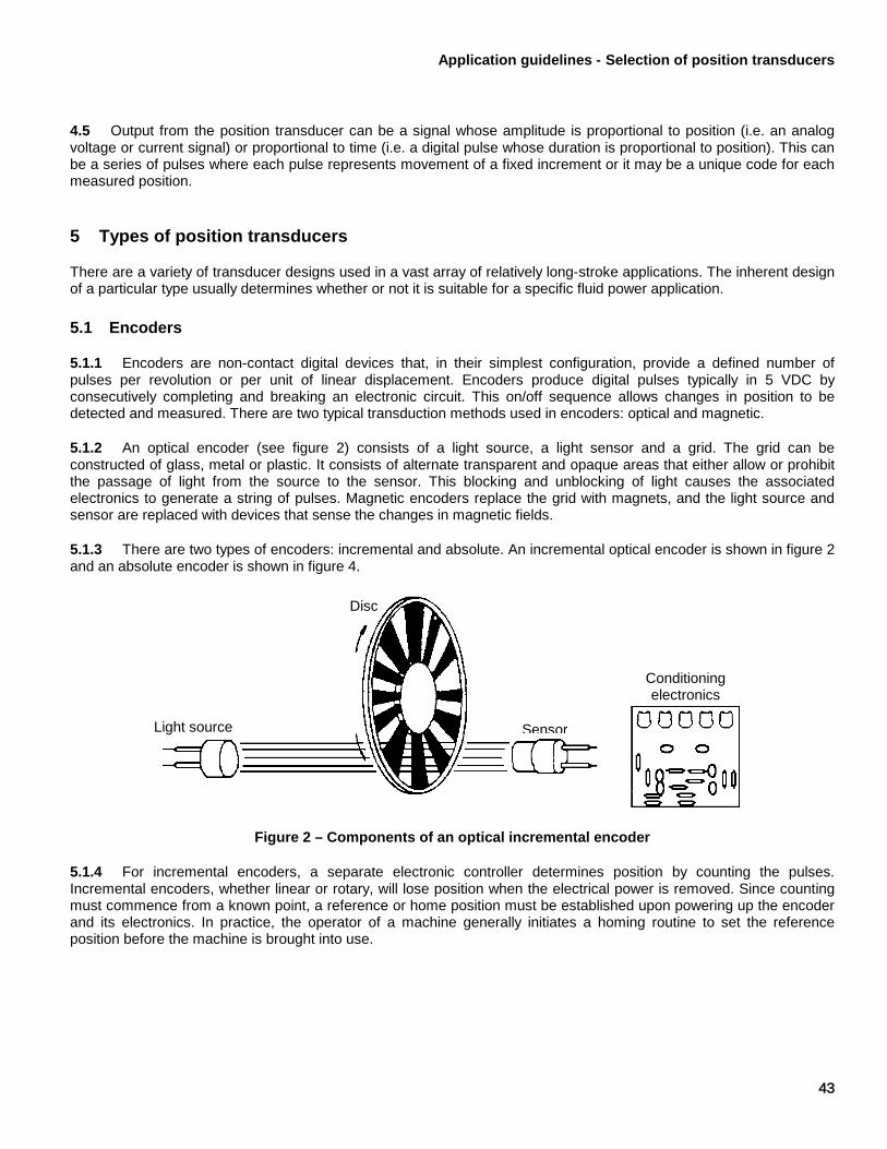
Application guidelines - Selection of position transducers
43
4.5 Output from the position transducer can be a signal whose amplitude is proportional to position (i.e. an analog voltage or current signal) or proportional to time (i.e. a digital pulse whose duration is proportional to position). This can be a series of pulses where each pulse represents movement of a fixed increment or it may be a unique code for each measured position.
5 Types of position transducers
There are a variety of transducer designs used in a vast array of relatively long-stroke applications. The inherent design of a particular type usually determines whether or not it is suitable for a specific fluid power application.
5.1 Encoders
5.1.1 Encoders are non-contact digital devices that, in their simplest configuration, provide a defined number of pulses per revolution or per unit of linear displacement. Encoders produce digital pulses typically in 5 VDC by consecutively completing and breaking an electronic circuit. This on/off sequence allows changes in position to be detected and measured. There are two typical transduction methods used in encoders: optical and magnetic.
5.1.2 An optical encoder (see figure 2) consists of a light source, a light sensor and a grid. The grid can be constructed of glass, metal or plastic. It consists of alternate transparent and opaque areas that either allow or prohibit the passage of light from the source to the sensor. This blocking and unblocking of light causes the associated electronics to generate a string of pulses. Magnetic encoders replace the grid with magnets, and the light source and sensor are replaced with devices that sense the changes in magnetic fields.
5.1.3 There are two types of encoders: incremental and absolute. An incremental optical encoder is shown in figure 2 and an absolute encoder is shown in figure 4.
Figure 2 – Components of an optical incremental encoder
5.1.4 For incremental encoders, a separate electronic controller determines position by counting the pulses. Incremental encoders, whether linear or rotary, will lose position when the electrical power is removed. Since counting must commence from a known point, a reference or home position must be established upon powering up the encoder and its electronics. In practice, the operator of a machine generally initiates a homing routine to set the reference position before the machine is brought into use.
Disc
Conditioning electronics
Light source Sensor

Application guidelines - Selection of position transducers
44
5.1.5 To ensure that an incremental encoder can determine direction, a second pulse output is added 90° out of phase with the first output. This phase shift is referred to as quadrature output (see figure 3) and it allows the controller to determine direction of travel and eliminates false counts caused by vibration when motion has stopped. A third output generates a single index pulse at a discrete position. This output is generally used for homing or indexing routines and for counting turns in rotary multiturn applications.
Figure 3 – Quadrature = 90°
5.1.6 Typical absolute encoders overcome this loss of position sensing by using an elaborate pattern on the grid with eight or more light source detector pairs that generate parallel pulse outputs, which are available in a variety of output formats. The combination of elaborate patterns and number of light source detector pairs provides a number of unique outputs for the travel of the device.
Figure 4 – Absolute encoder disc
5.1.7 For incremental encoders, the higher the line count, the greater the resolution of the device. For absolute encoders, the greater the number of outputs, the greater the resolution of the device. The cost of the encoder increases as resolution becomes greater.
5.2 Inductive sensors
5.2.1 An inductive sensor is a non-contact device that measures the change in impedance (effective resistance) of a coil. The operation is similar to that of an inductive proximity switch. Alternating current flowing through a coil forms a magnetic field around the coil. Ferrous metal or non-ferrous metal at higher frequencies disrupts the field when the metal enters it. The disruption of the field causes the inductance of the coil to change.
Track A
Track B
90°
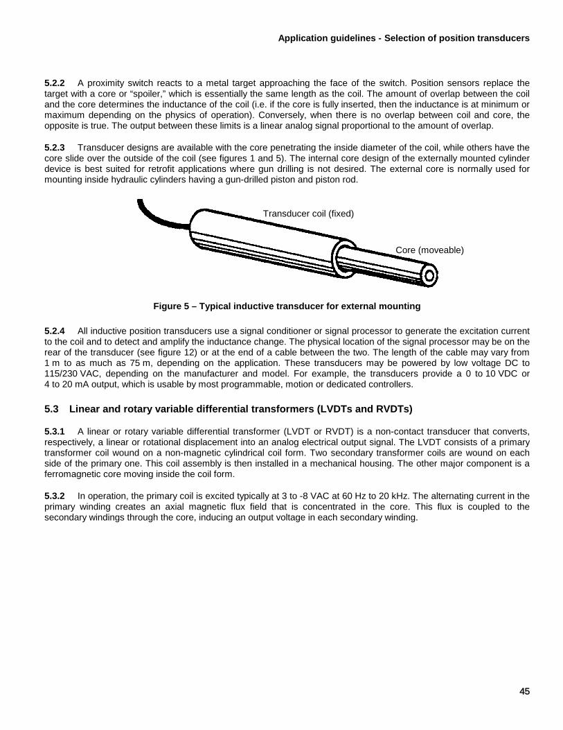
Application guidelines - Selection of position transducers
45
5.2.2 A proximity switch reacts to a metal target approaching the face of the switch. Position sensors replace the target with a core or “spoiler,” which is essentially the same length as the coil. The amount of overlap between the coil and the core determines the inductance of the coil (i.e. if the core is fully inserted, then the inductance is at minimum or maximum depending on the physics of operation). Conversely, when there is no overlap between coil and core, the opposite is true. The output between these limits is a linear analog signal proportional to the amount of overlap.
5.2.3 Transducer designs are available with the core penetrating the inside diameter of the coil, while others have the core slide over the outside of the coil (see figures 1 and 5). The internal core design of the externally mounted cylinder device is best suited for retrofit applications where gun drilling is not desired. The external core is normally used for mounting inside hydraulic cylinders having a gun-drilled piston and piston rod.
Figure 5 – Typical inductive transducer for external mounting
5.2.4 All inductive position transducers use a signal conditioner or signal processor to generate the excitation current to the coil and to detect and amplify the inductance change. The physical location of the signal processor may be on the rear of the transducer (see figure 12) or at the end of a cable between the two. The length of the cable may vary from 1 m to as much as 75 m, depending on the application. These transducers may be powered by low voltage DC to 115/230 VAC, depending on the manufacturer and model. For example, the transducers provide a 0 to 10 VDC or 4 to 20 mA output, which is usable by most programmable, motion or dedicated controllers.
5.3 Linear and rotary variable differential transformers (LVDTs and RVDTs)
5.3.1 A linear or rotary variable differential transformer (LVDT or RVDT) is a non-contact transducer that converts, respectively, a linear or rotational displacement into an analog electrical output signal. The LVDT consists of a primary transformer coil wound on a non-magnetic cylindrical coil form. Two secondary transformer coils are wound on each side of the primary one. This coil assembly is then installed in a mechanical housing. The other major component is a ferromagnetic core moving inside the coil form.
5.3.2 In operation, the primary coil is excited typically at 3 to -8 VAC at 60 Hz to 20 kHz. The alternating current in the primary winding creates an axial magnetic flux field that is concentrated in the core. This flux is coupled to the secondary windings through the core, inducing an output voltage in each secondary winding.
Transducer coil (fixed)
Core (moveable)

Application guidelines - Selection of position transducers
46
5.3.3 When the core is centered between the two identical secondary windings, the voltage induced in each is identical (see figure 6). The voltage induced in Secondary a (Va) is in phase and Secondary b (Vb) will be 180° out of phase with the excitation voltage. The output, Va-Vb will be zero. The core position where the output voltage (Va-Vb) is zero is referred to as the null position.
NOTE The physical appearance of an LVDT maybe similar to that of an inductive sensor.
Figure 6 – Typical LVDT
5.3.4 When the core is moved in either direction from the null position, the amplitude of Va -Vb changes in direct proportion to the displacement. The phase relationships of the summed output with the excitation also change. In one direction, the summed output signal will be in phase with the excitation and 180° out of phase in the other direction. The summed output voltage, therefore, has two components: 1) amplitude indicating the magnitude of the displacement and 2) phase relationship indicating direction of displacement. A typical in-cylinder mounting configuration is shown in figure 1. The LVDT normally uses a special signal conditioning circuit called a phase sensitive demodulator, which reconstructs the polarity of the DC output voltage.
5.3.5 For most applications, such as the one shown in figure 7, you will not need to be concerned with connecting directly with the AC voltage coils. A signal conditioner, either external or internal to the transducer, will generate the excitation and provide DC voltage or current output that is proportional to displacement of the core. When the signal conditioner is included in the package, the package is referred to as a DCDT. If the input motion is rotational, the device is referred to as a RVDT.
Excitation
Vp
Core Displacement
Secondary b Secondary a
Vb Va
Va-Vb
Primary
Application guidelines - Selection of position transducers
47
5.4 Magnetostriction
5.4.1 Magnetostriction is a property of some ferromagnetic materials in which the material expands or contracts when placed in a magnetic field (see figure 8). The sensing element of a magnetostrictive position sensor is the waveguide, a long, thin ferromagnetic wire or tube. Another property of these materials is the Wiedemann effect: when a current is passed through the waveguide in the presence of an axial magnetic filed, a torsional force is exerted on the waveguide.
5.4.2 The sequence of events in a position measurement is:
a) a current pulse, called the interrogation pulse, is applied to the waveguide (the circuit is completed with a copper return wire) and a timer is started;
b) a torsional force is generated at the location of the position magnet due to the Wiedemann effect. This produces a sonic pulse that travels down the waveguide, traveling at the speed of sound in the waveguide material;
c) when the sonic pulse arrives at the sensor element head, it is detected and the timer is stopped;
d) the elapsed time represents the distance between the position magnet and the sensor element head. Long-term stability and temperature sensitivity are controlled by the speed of sound in the waveguide material;
e) the time period measurement is used to produce the desired output, such as analog voltage, 4 to 20 mA, pulse width modulation, CANbus, Synchronous Serial Interface (SSI), etc.
5.4.3 Accurate, non-contact position sensing is thus achieved with absolutely no wear to any of the sensing elements. Since a return pulse will be generated for each magnet located along the sensor, sensors can be designed with multiple marker magnets.
5.4.4 The magnetostrictive linear displacement transducer (MLDT) relies on the basic principle of magnetostriction, which causes some ferromagnetic materials to change dimension when subjected to magnetic fields. The construction of a typical MLDT includes an electronic sensing head and a conducting wire coaxially mounted in a waveguide. The waveguide is made of a magnetostrictive material that is mounted within a protective housing made of a non-magnetic material. The waveguide is spring mounted on one end for damping. An external magnet moves along the exterior of the housing.
5.4.5 A current (interrogation) pulse is launched along the conducting wire in the waveguide. This generates a circumferential magnetic field around the waveguide as the current in the pulse travels down the conducting wire. When the magnetic field from the current (interrogation) pulse intersects the field of the external magnet, the interaction of the two fields form a third field that causes the waveguide to experience a minute torsional strain or twist. The strain pulse travels at ultrasonic speeds along the waveguide and into a pickup mounted in the head of the instrument.
5.4.6 There are different methods of sensing the torsional strain pulse. Each of the variations of strain pulse sensing detects the dynamic strain induced in the waveguide and produces a signal that is sent to the conditioning electronics for amplification and shaping.
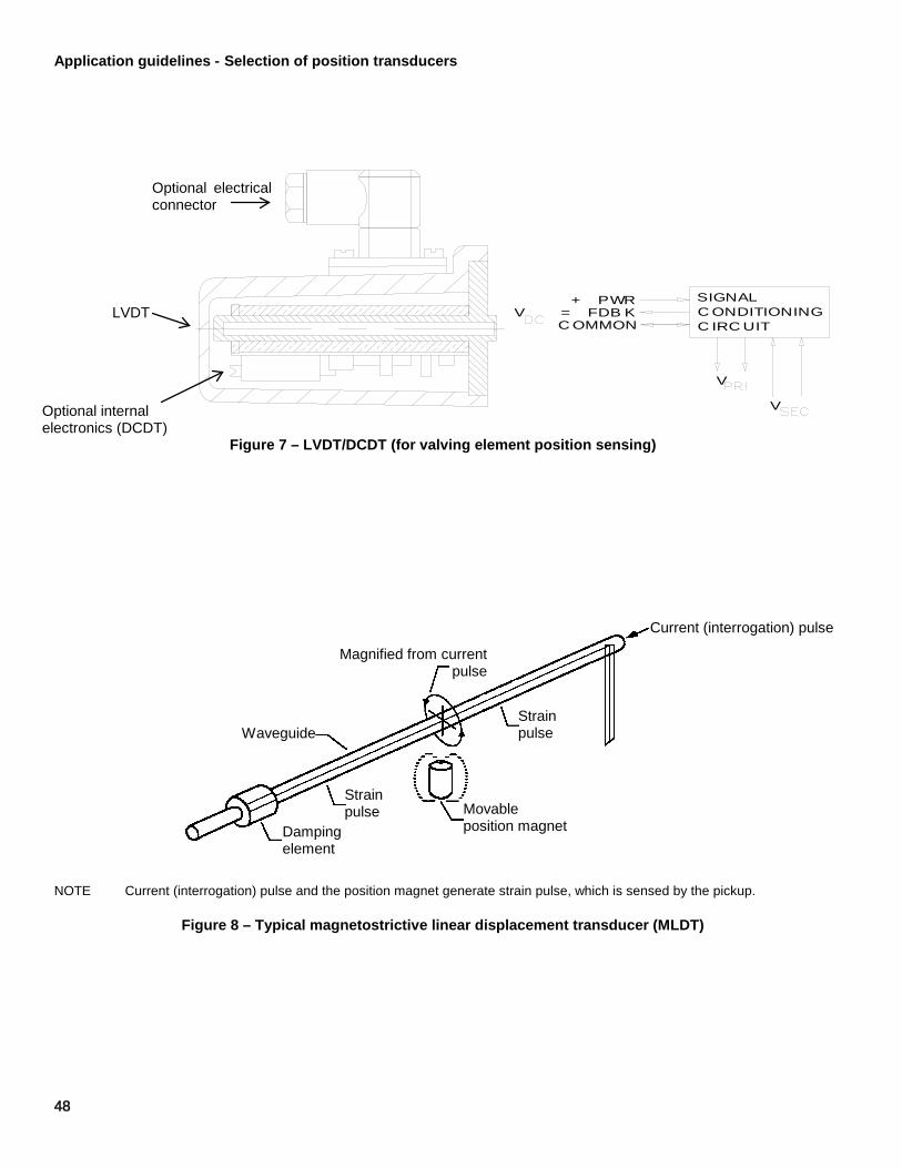
Application guidelines - Selection of position transducers
48
SIGNALC ONDITIONINGC IRC UIT
+ PWRV = FDB K
C OMMON
V
V
Figure 7 – LVDT/DCDT (for valving element position sensing)
NOTE Current (interrogation) pulse and the position magnet generate strain pulse, which is sensed by the pickup.
Figure 8 – Typical magnetostrictive linear displacement transducer (MLDT)
Optional electrical connector
LVDT
Optional internal electronics (DCDT)
Current (interrogation) pulse
Strain pulse
Magnified from current pulse
Movable position magnet
Strain pulse
Waveguide
Damping element

Application guidelines - Selection of position transducers
49
5.4.7 The precise position of the magnet is determined from the time interval between the initiation of the current (interrogation) pulse and the arrival of the torsional strain pulse in the head, as seen in figure 9. This time interval multiplied by the travel speed of the strain pulse along the waveguide indicates the position.
Figure 9 – Waveshapes
5.4.8 The output is digital in nature. The most common are start/stop and pulse width modulated (PWM). These electronic circuits are either self-contained or available as a separate module. An analog conversion is readily available that generally provides 0-10 VDC or 4-20 mA as an output interface. Most units use DC excitation. The output is available in SSI, CANbus, Profibus, DeviceNet, Ethernet and others.
5.4.9 MLDTs are available in external and internal mounting configurations. Internal mounting resembles the one shown in figure 10. The piston rod is hollow to allow the stationary waveguide tube to fit inside as the piston rod retracts. A magnet is embedded in the piston to allow the MLDT to generate a feedback signal representing position of the piston and, therefore, the load.
(A) a thin ribbon passing through a coil (B) a coil directly sensing the pulse (C) a piezoelectric element mechanically sensing the pulse
Figure 10 – Three methods of sensing a strain pulse
(A) Waveguide
(B) Waveguide
(C) Waveguide
Mode converter
Pickup coil Pickup coil
Bias magnet
Piezoelectric film
Leads

Application guidelines - Selection of position transducers
50
5.4.10 Recently, new applications referred to as “embedded” have positioned the electronics housing adjacent to the cylinder end cap instead of inline with the probe on the back of the end cap, as illustrated in figure 11.
NOTE The illustration above represents a typical cylinder with a 3- to 8-inch bore. Some installation requirements may be application specific.
Figure 11 – Adjacent magnostrictive
Cylinder end cap
Sensor retaining screw (customer supplied)
Electrical stroke Dead zone
(stroke dependent)
End cap (ref)
Cable
Magnet
Piston head and rod assembly
Spacer Chamfered rod bushing (Customer provided, optional)
Adapter plate
To pigtail cable or connector

Application guidelines - Selection of position transducers
51
5.4.11 Where aluminum, stainless steel or non-metallic cylinder tubes are used, non-contact external mounting without the need to mechanically couple the transducer to the piston rod may be used, as illustrated in figure 12. In this technology, the transducer waveguide element obtains position information from magnetic fields induced from piston-mounted magnets used for standard reed and Hall switches.
Figure 12 – Non-contact external mount
5.5 Resistive sensors
5.5.1 A resistive sensor, commonly called a potentiometer, uses electrical resistance as a means of measuring position. An electrical circuit is established between the two ends of the conductive strip of material (see figure 13). A constant voltage is applied across the conductive strip. A wiper moves along the strip and picks up the voltage along the strip. Voltage increases as the wiper moves closer to the positive end of the strip. These resistive sensors are available in either linear motion or rotary motion designs.
NOTE With V1 constant, a hydraulic cylinder or other component moving up or down with the wiper causes voltage Vo to increase or decrease, respectively.
Figure 13 – Electrical schematic of resistive transducer
Resistance
Wiper
Vo
V1
+
-
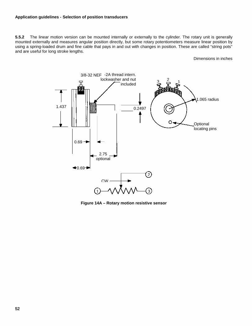
Application guidelines - Selection of position transducers
52
5.5.2 The linear motion version can be mounted internally or externally to the cylinder. The rotary unit is generally mounted externally and measures angular position directly, but some rotary potentiometers measure linear position by using a spring-loaded drum and fine cable that pays in and out with changes in position. These are called “string pots” and are useful for long stroke lengths.
Dimensions in inches
Figure 14A – Rotary motion resistive sensor
1.437
0.69
0.69
2.75 optional
0.2497
Optional locating pins
1.065 radius
-2A thread intern. lockwasher and nut
included
3/8-32 NEF
1 3
2 CW
1 2 3

Application guidelines - Selection of position transducers
53
Figure 14B – Linear motion resistive sensor
5.5.3 The output of a resistive sensor is ratiometric to the voltage the user applies. Since resistive sensors are not generally provided with any form of signal conditioning electronics, the user is responsible to ensure appropriate electrical parameters are evaluated. These parameters include, but are not limited to, excitation voltage, power dissipation and wiper current as it relates to the input impedance of the controller. As a rule of thumb, the resistance of the device should be less than 0,1 times the resistance of the controller to assure better linearity.
5.6 Hall effect position transducers (Hall effect sensors)
5.6.1 A Hall effect position transducer is a non-contact device that detects the position of a magnet. The magnet moves along the length of the sensing element and is attached to the object whose position is to be determined.
5.6.2 The Hall effect position transducer relies on the basic principle of magnetic flux, forcing electrons to one side of a plate generating a voltage. The generation of voltage is known as the Hall effect. Only the perpendicular component of the flux is measured on the sensor.
5.6.3 There are different types of Hall effect position transducers available. The least expensive Hall effect position transducers are switches and latches, which have a digital output in response to the presence of a magnetic signal. More expensive are the linear devices, which output a voltage proportional to the perpendicular flux. Sensors are available in a variety of packages from small printed circuit board mounted sensors to fully enclosed fluid tight sensors used on hydraulic valves. The voltage and current requirements vary widely depending on manufacturer and type.
5.6.4 The flux path can be created for different purposes. For linear position feedback, the magnet would be moved in front of a linear Hall effect position transducer to obtain a linear voltage signal proportional to position, as shown in figure 15.
Green Yellow
Red
2 in up to 12-1/2 in 0.750
0.750
Shaft free to rotate
1
2
3 Yellow
Red
Green
Out In

Application guidelines - Selection of position transducers
54
S N
Figure 15 – Linear position feedback using Hall effect position transducer and magnet
5.6.5 Alternatively, a pulse waveform can be created from a digital output Hall effect position transducer and a series of varying flux fields moved in front of the sensor. Placing a small magnet in the package with the Hall effect position transducer sometimes augments this application. By adding the magnet to the sensor, the assembly becomes a sensor to ferrous materials. If there is no ferrous material present, the Hall effect switch is off. If there is ferrous material, the flux increases and the digital Hall effect switches on. Classically, this application is used for gear tooth timing and counting on engines.
5.6.6 For hydraulic applications, Hall effect position transducers can be used for valving element position feedback, cylinder position feedback, safety presence or rotary position feedback. In general, linear Hall effect position transducers are good candidates for short motion measurement (<0.1 m) or limited rotary motion measurement (<180°).
6 Measurement error
6.1 All position transducers are electromechanical devices and are made from more than one material. For this and other reasons, they respond not only to changes in position, but also to variations in temperature, shock, vibration and excitation. The output of the transducer will likely vary if operated from one end of its specified temperature range to the other end. The electronics may also experience catastrophic failure if subjected to prolonged exposure at temperature, vibration and humidity levels beyond the manufacturer's specifications.
6.2 There are many other characteristics such as linearity, hysteresis, repeatability, etc., that help quantify the measurement accuracy of a position transducer. Other factors, though equally important, are more elusive and include
Output
Distance from neutral
Hall effect position transducer
Stationary magnet

Application guidelines - Selection of position transducers
55
packaging, configuration, materials of construction and internal design. Each of these can be appraised only on the basis of field-testing and/or experience.
6.3 All of the above factors must be considered along with the particulars of the application and the expertise of the individuals involved in making the system perform as required. The wise buyer will choose a transducer based on operating principles, specifications, price and the reputation of the seller.
7 Physical considerations
7.1 Two important considerations are the operating principle and the construction of the transducer. Both of these considerations affect size, life, accessibility, maintainability and durability. The operating principle also influences linearity, repeatability, resolution, temperature sensitivity, maximum velocity/response time and interface.
7.2 The operating principle involves the choice between a contact vs. non-contact type device. A properly installed non-contact type device will typically have less maintenance and greater longevity than a contact type device.
7.3 The operating principle also determines the complexity of the signal-conducting electronics. A contact type device, such as a resistive sensor, requires simpler electronics than non-contacting devices and, thus, is generally less expensive. Additionally, the package length is closer to the operating length of the resistive sensor.
7.4 A transducer's internal construction must be rugged enough to stand up to physical abuse. The construction of the position transducer installed in a cylinder may be dictated by the fluid media temperature or pressure. A protruding transducer can make a convenient step for maintenance personnel climbing on the equipment. Falling debris is another potential source of physical damage to the transducer or interconnect cables. When possible, transducers should be accessible, but not in areas subjected to potentially damaging conditions. Internal mounting of the transducers may be the best way of protecting the device.
8 Other specifications
8.1 There are many design features that do not appear in published specifications but that may be important over the life of the application. These design factors and technologies all need to be examined against the user's actual applications.
8.2 For transducers mounted on moving structures, one needs to consider mounting orientation, cable length and routing. Certain locations or attitudes subject the transducer to severe vibration that can cause catastrophic failure.
8.3 External mounting is often preferred for retrofit applications because the expense of gun drilling and machining the cylinder is avoided.
9 Application considerations
9.1 One of the first operating characteristics that should be considered is whether the transducer is a contact or non-contact device. These considerations are summarized in table 1.
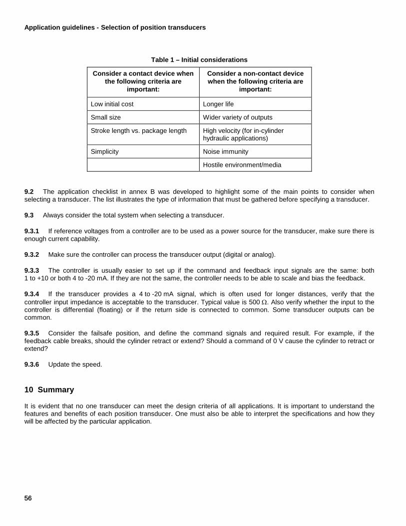
Application guidelines - Selection of position transducers
56
Table 1 – Initial considerations
Consider a contact device when the following criteria are
important:
Consider a non-contact device when the following criteria are
important:
Low initial cost Longer life
Small size Wider variety of outputs
Stroke length vs. package length High velocity (for in-cylinder hydraulic applications)
Simplicity Noise immunity
Hostile environment/media
9.2 The application checklist in annex B was developed to highlight some of the main points to consider when selecting a transducer. The list illustrates the type of information that must be gathered before specifying a transducer.
9.3 Always consider the total system when selecting a transducer.
9.3.1 If reference voltages from a controller are to be used as a power source for the transducer, make sure there is enough current capability.
9.3.2 Make sure the controller can process the transducer output (digital or analog).
9.3.3 The controller is usually easier to set up if the command and feedback input signals are the same: both 1 to +10 or both 4 to -20 mA. If they are not the same, the controller needs to be able to scale and bias the feedback.
9.3.4 If the transducer provides a 4 to -20 mA signal, which is often used for longer distances, verify that the controller input impedance is acceptable to the transducer. Typical value is 500 Ω. Also verify whether the input to the controller is differential (floating) or if the return side is connected to common. Some transducer outputs can be common.
9.3.5 Consider the failsafe position, and define the command signals and required result. For example, if the feedback cable breaks, should the cylinder retract or extend? Should a command of 0 V cause the cylinder to retract or extend?
9.3.6 Update the speed.
10 Summary
It is evident that no one transducer can meet the design criteria of all applications. It is important to understand the features and benefits of each position transducer. One must also be able to interpret the specifications and how they will be affected by the particular application.

Application guidelines - Selection of position transducers
57
Annex A (informative)
Glossary
A.1 ambient conditions: The conditions of the medium surrounding the case of the transducer.
A.2 CPC: Counts per centimeter.
A.3 CPI: Counts per inch.
A.4 CPR: Counts per revolution. The output pulses from an encoder. This is related to the number of light source interruptions made by the scale. This quantity is also referred to as pulses per revolution (PPR).
A.5 compensation: Provision of a supplemental device, circuit or special materials to counteract known sources of error. Its manufacturer typically builds these circuits into the transducer.
A.6 continuous rating: The rating applicable to a specified operation for an uninterrupted length of time.
A.7 drift: An undesired change in output over a period of time, which is not a function of displacement.
A.8 electromagnetic interference (EMI): An undesired change in the output of the transducer due to the presence of magnetic or electric fields near the transducer or system wiring. This is a complex subject treated by other standards writing organizations such as SAE, IEEE, FCC and ISO.
A.9 end points: The outputs at the specified upper and lower limits of the range of travel.
A.10 gradient: The inverse of the velocity of propagation of the magnetostrictive pulses through the waveguide.
A.11 insulation resistance: The resistance measured between specified insulated portions of a transducer when a specified DC voltage is applied at room conditions, unless otherwise stated.
A.12 load impedance: The impedance presented to the output terminals of a transducer by the associated external circuitry.
A.13 misalignment: The error resulting from mechanical deformation of the transducer during the mounting phase.
A.14 non-linearity: Linearity error. See also linearity (3.9).
A.15 sensitivity: The ratio of the change in transducer output to a change in the value of displacement.
A.16 span: The algebraic difference between the end points of the range.

Application guidelines - Selection of position transducers
58
Annex B (informative)
Application checklist
Use this checklist to help determine the type of position transducer needed for your application. Refer to the document or glossary for explanation, clarification and elaboration of the terminology and concepts contained in the checklist.
Performance Mechanical stroke: ______________ units _____________ Measurement stroke: ______________ units _____________ Maximum pressure (in hyd. cyl., if so mounted): _____________ units _____________ Desired repeatability: ______________ units _____________ Resolution: ______________ units _____________ Maximum hysteresis/linearity: __________ units _____________ Maximum velocity: ______________ units _____________
Environment Type of application: ______________ Industrial _________ Mobile ______________ Laboratory ________ Other Pressure media (type of fluid): ______________________________________ Vibration: Low __________ Medium ___________ High _____________ Shock: Low __________ Medium ___________ High _____________ Humidity: Low __________ Normal ___________ High _____________ Hazardous environment exposure (yes or no) _____________ If yes type _________ Operating temperature: of fluid: Minimum _______________ Maximum _________ ambient: Minimum _______________ Maximum _________ Storage temperature: of fluid: Minimum _______________ Maximum _________ ambient: Minimum _______________ Maximum _________ Agency/certification: ________________________________________ CE mark: _______________________________________________ NEMA/IP class: _______________________________________________
Electrical Input (excitation): AC __________ DC _______________ Current __________ Other _________ Output requirements: mV ______ V _______________ 4 – 20 mA _________ Hz _______________________ CPC (CPI) or CPR ___________________ Other___________ EMI exposure: low ____________ medium ___________ high _____________ Other _____________________________________________ Zero adjust: (yes or no) ______________ Full scale adjust: (yes or no) ___________ Response time:__________ ___________ units ____________
Current consumption: Other Physical Maximum size: ________ x ________________ x _____________ units Weight: ______________ units _____________ Mounting: Foot _________ Rod end(s) _______ Shaft _________ Integral __________ Other ________ Termination: Cable __________ length ___________ units __________ Terminals _______ type _____________ Connector ______ type _____________