Embed Size (px)
Citation preview
CS 3410 Computer System Organizationand Programming
Guest Lecture: I/O Devices
Christopher Batten
Computer Systems LaboratorySchool of Electrical and Computer Engineering
Cornell University
Spring 2012
I/O Device Overview Programmed I/O vs. Mem-Mapped I/O Polling-Based I/O vs. Interrupt-Based I/O Direct-Mem Access
Agenda
I/O Device Examples,Organization, and Drivers
Programmed I/O vs.Memory-Mapped I/O
Polling-Based I/O vs.Interrupt-Based I/O
Direct-Memory Access
CS 3410 I/O Devices – Christopher Batten 2 / 50
• I/O Device Overview • Programmed I/O vs. Mem-Mapped I/O Polling-Based I/O vs. Interrupt-Based I/O Direct-Mem Access
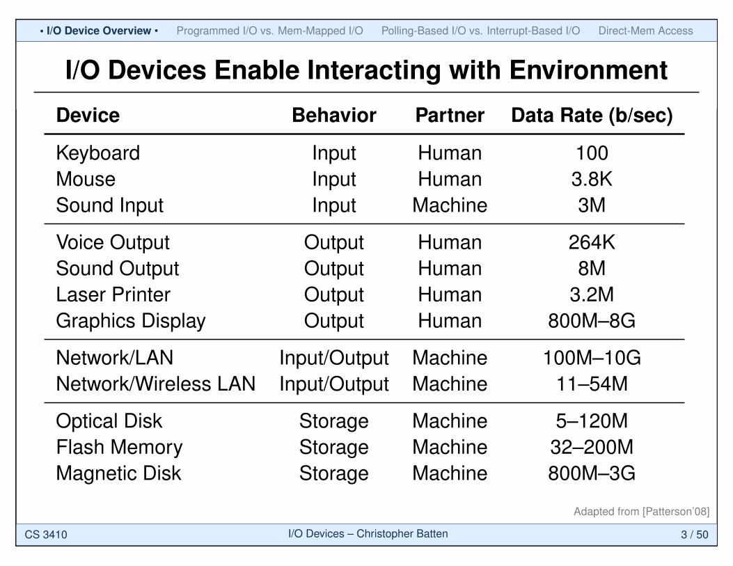
I/O Devices Enable Interacting with Environment
Device Behavior Partner Data Rate (b/sec)
Keyboard Input Human 100Mouse Input Human 3.8KSound Input Input Machine 3M
Voice Output Output Human 264KSound Output Output Human 8MLaser Printer Output Human 3.2MGraphics Display Output Human 800M–8G
Network/LAN Input/Output Machine 100M–10GNetwork/Wireless LAN Input/Output Machine 11–54M
Optical Disk Storage Machine 5–120MFlash Memory Storage Machine 32–200MMagnetic Disk Storage Machine 800M–3G
Adapted from [Patterson’08]
CS 3410 I/O Devices – Christopher Batten 3 / 50
• I/O Device Overview • Programmed I/O vs. Mem-Mapped I/O Polling-Based I/O vs. Interrupt-Based I/O Direct-Mem Access
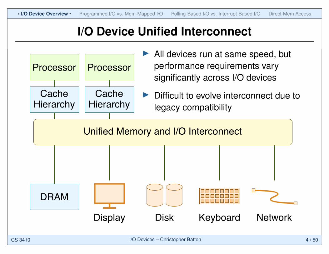
I/O Device Unified Interconnect
Processor Processor
CacheHierarchy
CacheHierarchy
DRAM
Display Disk Keyboard Network
Unified Memory and I/O Interconnect
I All devices run at same speed, butperformance requirements varysignificantly across I/O devices
I Difficult to evolve interconnect due tolegacy compatibility
CS 3410 I/O Devices – Christopher Batten 4 / 50
• I/O Device Overview • Programmed I/O vs. Mem-Mapped I/O Polling-Based I/O vs. Interrupt-Based I/O Direct-Mem Access
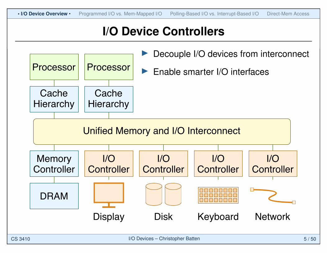
I/O Device Controllers
Processor Processor
CacheHierarchy
CacheHierarchy
DRAM
Display Disk Keyboard Network
Unified Memory and I/O Interconnect
I/OController
MemoryController
I/OController
I/OController
I/OController
I Decouple I/O devices from interconnect
I Enable smarter I/O interfaces
CS 3410 I/O Devices – Christopher Batten 5 / 50
• I/O Device Overview • Programmed I/O vs. Mem-Mapped I/O Polling-Based I/O vs. Interrupt-Based I/O Direct-Mem Access
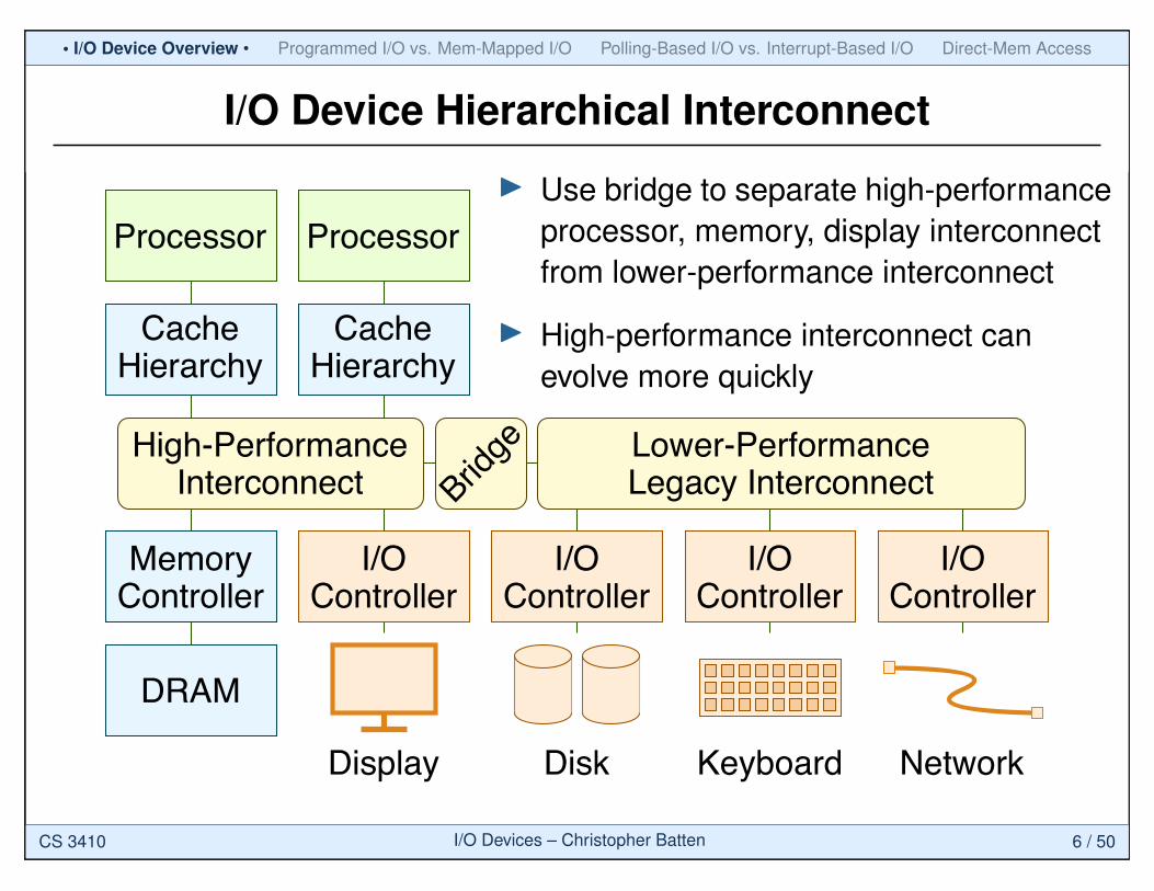
I/O Device Hierarchical Interconnect
Processor Processor
CacheHierarchy
CacheHierarchy
DRAM
Display Disk Keyboard Network
I/OController
MemoryController
I/OController
I/OController
I/OController
High-PerformanceInterconnect
Lower-PerformanceLegacy InterconnectBrid
ge
I Use bridge to separate high-performanceprocessor, memory, display interconnectfrom lower-performance interconnect
I High-performance interconnect canevolve more quickly
CS 3410 I/O Devices – Christopher Batten 6 / 50
• I/O Device Overview • Programmed I/O vs. Mem-Mapped I/O Polling-Based I/O vs. Interrupt-Based I/O Direct-Mem Access
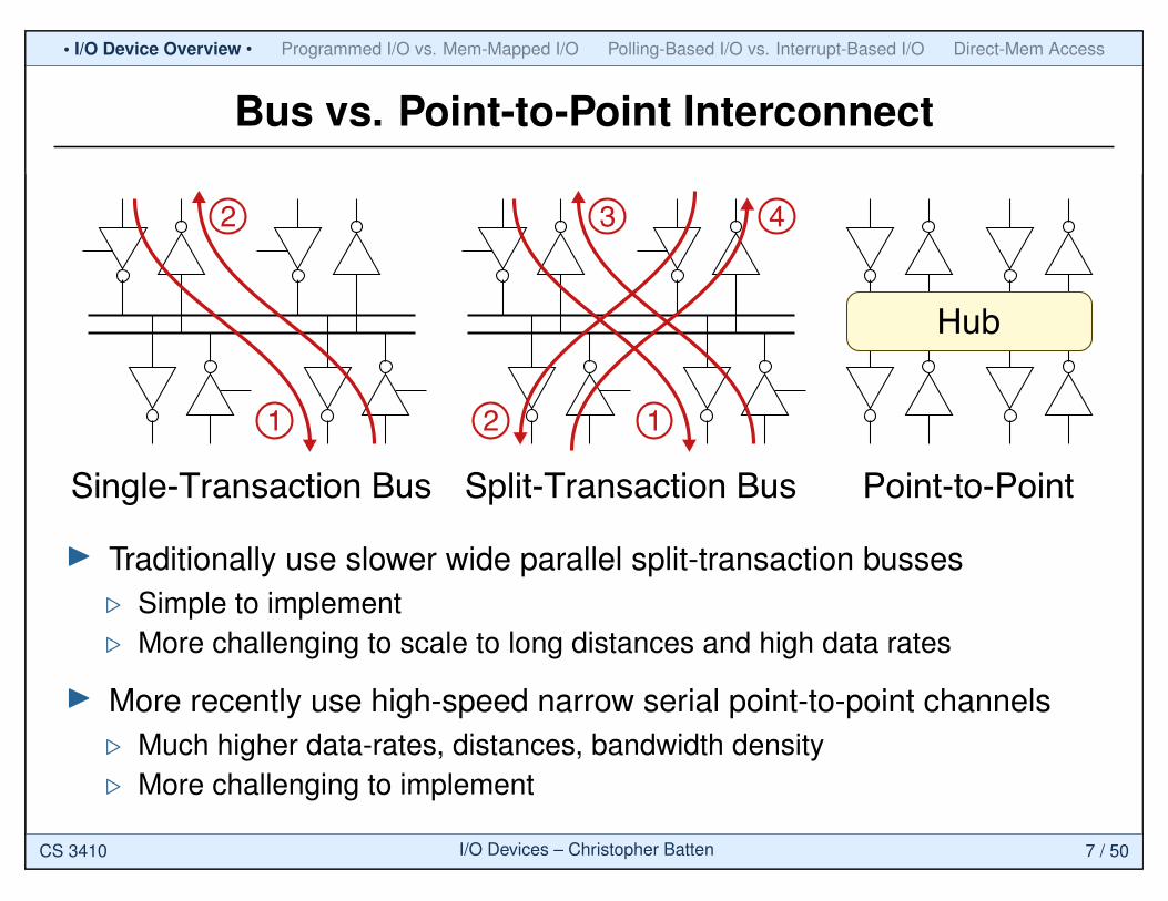
Bus vs. Point-to-Point Interconnect
Single-Transaction Bus
1
2
Split-Transaction Bus
12
3 4
Hub
Point-to-Point
I Traditionally use slower wide parallel split-transaction busses. Simple to implement. More challenging to scale to long distances and high data rates
I More recently use high-speed narrow serial point-to-point channels. Much higher data-rates, distances, bandwidth density. More challenging to implement
CS 3410 I/O Devices – Christopher Batten 7 / 50
• I/O Device Overview • Programmed I/O vs. Mem-Mapped I/O Polling-Based I/O vs. Interrupt-Based I/O Direct-Mem Access
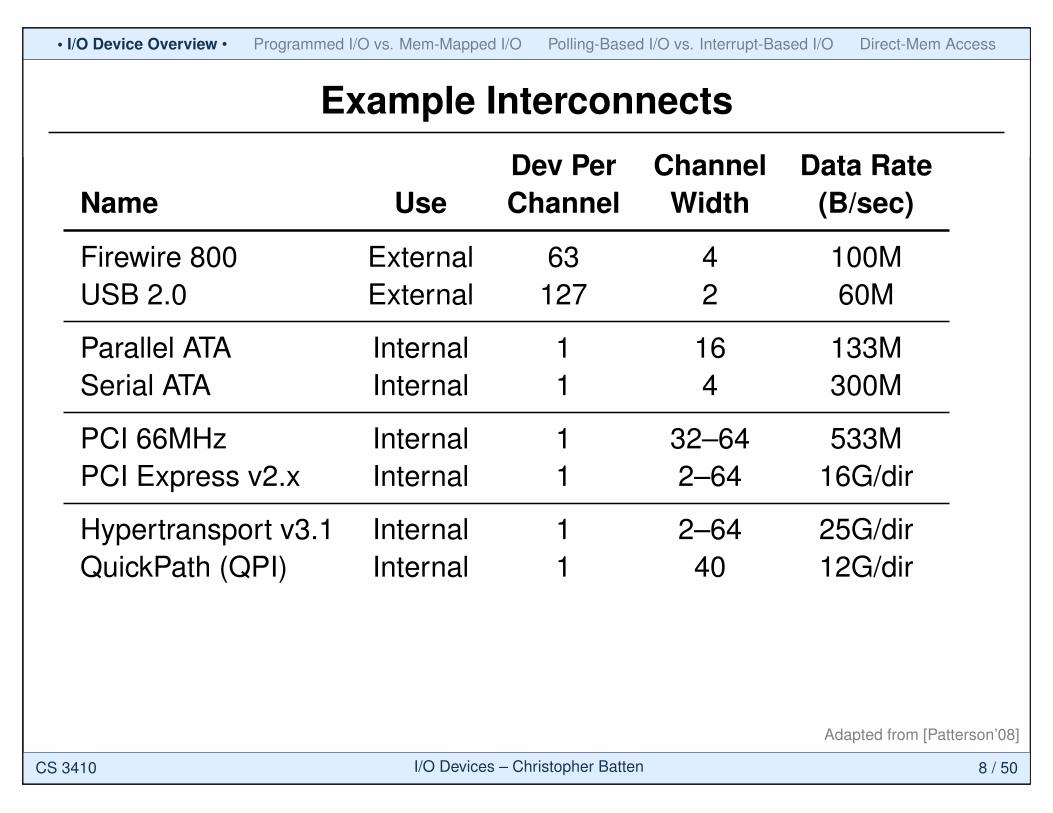
Example Interconnects
Dev Per Channel Data RateName Use Channel Width (B/sec)
Firewire 800 External 63 4 100MUSB 2.0 External 127 2 60M
Parallel ATA Internal 1 16 133MSerial ATA Internal 1 4 300M
PCI 66MHz Internal 1 32–64 533MPCI Express v2.x Internal 1 2–64 16G/dir
Hypertransport v3.1 Internal 1 2–64 25G/dirQuickPath (QPI) Internal 1 40 12G/dir
Adapted from [Patterson’08]
CS 3410 I/O Devices – Christopher Batten 8 / 50
• I/O Device Overview • Programmed I/O vs. Mem-Mapped I/O Polling-Based I/O vs. Interrupt-Based I/O Direct-Mem Access
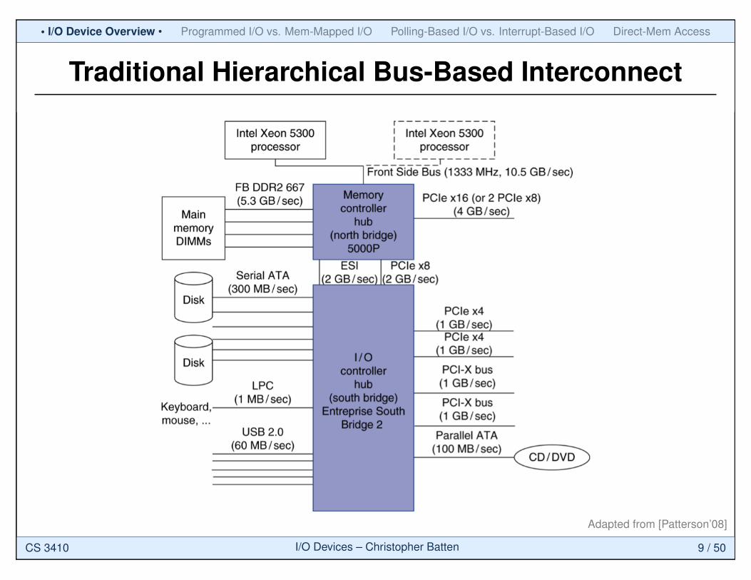
Traditional Hierarchical Bus-Based Interconnect
Adapted from [Patterson’08]
CS 3410 I/O Devices – Christopher Batten 9 / 50
• I/O Device Overview • Programmed I/O vs. Mem-Mapped I/O Polling-Based I/O vs. Interrupt-Based I/O Direct-Mem Access
13 Sun Fire X4150, X4250, and X4450 Server Architectures
Sun Microsystems, Inc.
Chapter 3
Sun Fire X4150, X4250, and X4450 Server Architectures
The Sun Fire X4150, X4250, and X4450 servers are designed to provide best-in-class
performance with high reliability and low power consumption. This chapter details
physical and architectural aspects of the systems, highlighting similarities and
differences between the server designs.
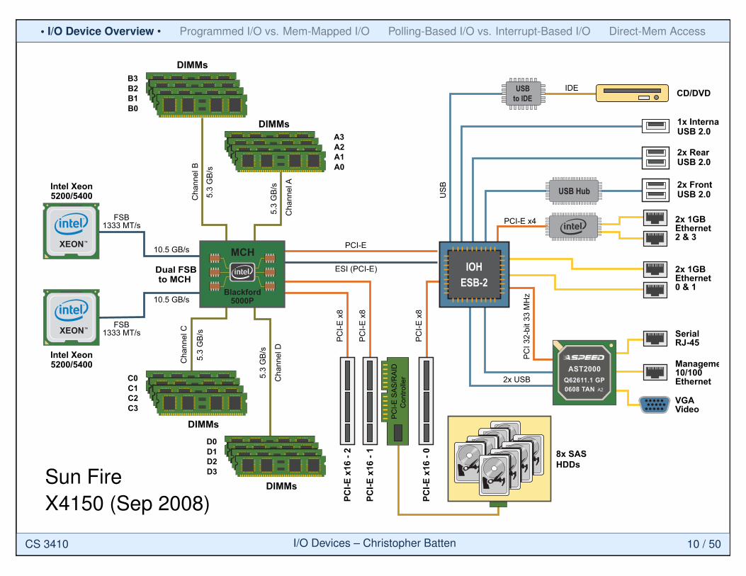
Sun Fire X4150 System-Level Architecture Figure 5 contains a system-level block diagram for Sun Fire X4150 servers. The
architecture of the Sun Fire X4150 server is similar to that of the Sun Fire X4250 and
X4450 servers — multiple host processors connect to a Northbridge Memory Controller
Hub (MCH) which in turn connects to a Southbridge I/O Hub (IOH). Details about key
subsystems (system chipsets, memory subsystems, I/O subsystems, etc.) are given later
in this chapter.
Figure 5. Block Diagram of Sun Fire X4150 Server with SAS drives
A2A3
A1A0
B2B3
B1B0
D1D0
D2D3
C1C0
C2C3
FSB1333 MT/s
FSB1333 MT/s
10.5 GB/s
10.5 GB/s
Dual FSBto MCH
XEONTM
XEONTM
Cha
nnel
A
5.3
GB/
s
Cha
nnel
B
5.3
GB/
s
Cha
nnel
C
5.3
GB/
s
Cha
nnel
D
5.3
GB/
s
PCI-E
x16
- 2
PCI-E
x16
- 1
PCI-E
x16
- 0
PCI-E
x8
PCI-E
x8
PCI-E
x8
8x SASHDDs
MCH
Blackford5000P
2x USB
PCI 3
2-bi
t 33
MH
z
PCI-E x4
AST2000Q62611.1 GP0608 TAN A2
2x RearUSB 2.0
1x InternalUSB 2.0
CD/DVD
2x FrontUSB 2.0
2x 1GBEthernet2 & 3
2x 1GBEthernet0 & 1
SerialRJ-45
Management10/100Ethernet
VGAVideo
USBto IDE
USB Hub
IOHESB-2
USB
PCI-E
ESI (PCI-E)
PC
I-E S
AS/R
AID
Con
trolle
r
DIMMs
DIMMs
DIMMs
DIMMs
Intel Xeon5200/5400
Intel Xeon5200/5400
IDE
Sun FireX4150 (Sep 2008)
CS 3410 I/O Devices – Christopher Batten 10 / 50
• I/O Device Overview • Programmed I/O vs. Mem-Mapped I/O Polling-Based I/O vs. Interrupt-Based I/O Direct-Mem Access
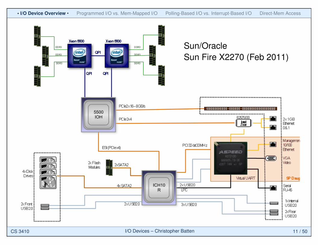
Oracle White Paper—Oracle’s Sun Fire X2270 M2 Server Architecture
8
Figure 3. The Sun Fire X2270 M2 server architecture emphasizes performance, memory bandwidth, and I/O capabilities.
Memory Architecture
The memory architecture of the Sun Fire X2270 M2 server contributes to the platform’s high performance. Each CPU includes a high-bandwidth, integrated DDR3 memory controller that reduces access latency. As many as six extended ECC memory modules per CPU are supported. Memory slots can be populated with the following low voltage DIMM types:
• 4 GB DDR3, 1,333 MT/sec
• 8 GB DDR3, 1,333 MT/sec
Memory DIMM population rules and best practices can help organizations create configurations with the best-possible performance.
• Because each processor contains a separate memory controller, a DIMM slot is accessible only when the corresponding processor slot is populated.
• For each memory channel, populate the DIMM slots that are the farthest from the CPU first. For example, populate D5, D3, and D1 first and then D4, D2, and D0 second. (DIMM numbering starts with D0 in the position closest to the processor and increases with proximity to the end of the memory bank.)
Sun/OracleSun Fire X2270 (Feb 2011)
CS 3410 I/O Devices – Christopher Batten 11 / 50
• I/O Device Overview • Programmed I/O vs. Mem-Mapped I/O Polling-Based I/O vs. Interrupt-Based I/O Direct-Mem Access
��������� �������������������� ���������������� �����������������
18
� Two Intel Xeon processor E5-2600 product family processors
� Up to 256 GB of memory (using 16 GB registered dual inline memory modules [RDIMMs]) populated in 16 registered RDIMM slots58 GB or 16 GB low-voltage RDIMMs are supported
� Four onboard 100/1,000/10,000 Mb/sec Ethernet ports
� Six external low-profile PCIe 3.0 slots (one 16-lane slot and five 8-lane slots)
� Six USB 2.0 ports (2 front, 2 rear, and 2 internal)
� An onboard Oracle ILOM service processor
� Two hot-swappable, high-efficiency power supply units (PSUs) for N+1 redundancy
� Four hot-swappable, variable-speed fan modules (for N+1 redundancy), each containing two counterrotating, low-vibration fans operating under environmental monitoring
System-Level Architecture: Sun Fire X4270 M3 Server with Eight 2.5-Inch Disks and DVD
To gain an understanding of the architecture of the Sun Fire X4270 M3 server with eight 2.5-inch disks and DVD+/-RW, see the system-level block diagram in Figure 15.
Figure 15. This block diagram depicts the Sun Fire X4270 M3 server with eight 2.5-inch disks and DVD+/-RW, including the required SAS HBA on PCIe slot 6.
Sun/Oracle Sun Fire X4170 (Apr 2012)
CS 3410 I/O Devices – Christopher Batten 12 / 50
• I/O Device Overview • Programmed I/O vs. Mem-Mapped I/O Polling-Based I/O vs. Interrupt-Based I/O Direct-Mem Access
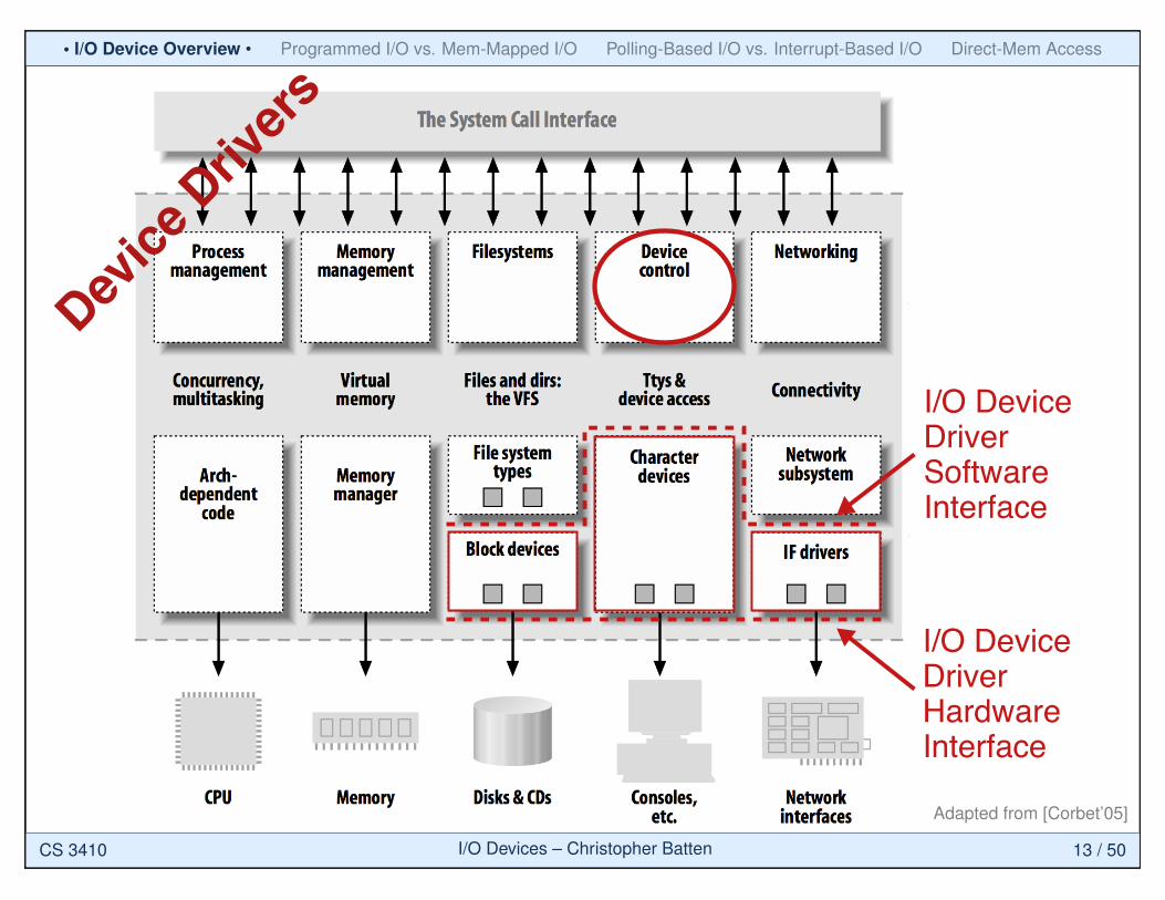
I/O DeviceDriverHardwareInterface
I/O DeviceDriverSoftwareInterface
Device
Driver
s
Adapted from [Corbet’05]
CS 3410 I/O Devices – Christopher Batten 13 / 50
• I/O Device Overview • Programmed I/O vs. Mem-Mapped I/O Polling-Based I/O vs. Interrupt-Based I/O Direct-Mem Access
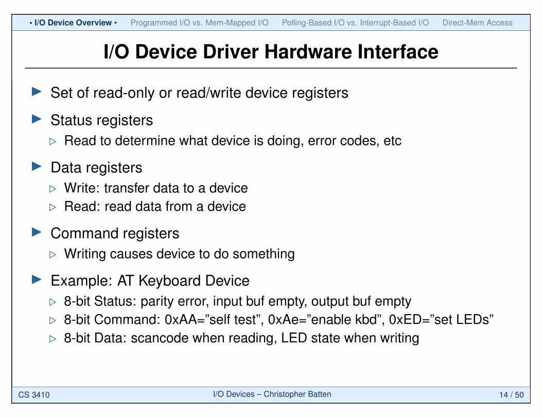
I/O Device Driver Hardware Interface
I Set of read-only or read/write device registers
I Status registers. Read to determine what device is doing, error codes, etc
I Data registers. Write: transfer data to a device. Read: read data from a device
I Command registers. Writing causes device to do something
I Example: AT Keyboard Device. 8-bit Status: parity error, input buf empty, output buf empty. 8-bit Command: 0xAA=”self test”, 0xAe=”enable kbd”, 0xED=”set LEDs”. 8-bit Data: scancode when reading, LED state when writing
CS 3410 I/O Devices – Christopher Batten 14 / 50
• I/O Device Overview • Programmed I/O vs. Mem-Mapped I/O Polling-Based I/O vs. Interrupt-Based I/O Direct-Mem Access
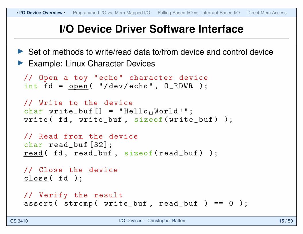
I/O Device Driver Software Interface
I Set of methods to write/read data to/from device and control deviceI Example: Linux Character Devices
// Open a toy "echo" character deviceint fd = open( "/dev/echo", O_RDWR );
// Write to the devicechar write_buf [] = "Hello World!";write( fd , write_buf , sizeof(write_buf) );
// Read from the devicechar read_buf [32];read( fd, read_buf , sizeof(read_buf) );
// Close the deviceclose( fd );
// Verify the resultassert( strcmp( write_buf , read_buf ) == 0 );
CS 3410 I/O Devices – Christopher Batten 15 / 50
• I/O Device Overview • Programmed I/O vs. Mem-Mapped I/O Polling-Based I/O vs. Interrupt-Based I/O Direct-Mem Access
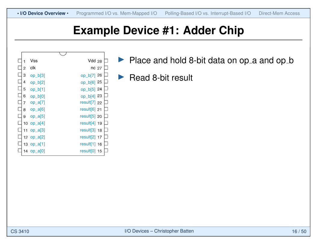
Example Device #1: Adder Chip
Vss
op_a[0]
op_a[1]
op_a[2]
op_a[3]
op_a[4]
op_a[5]
op_a[6]
op_a[7]
result[0]
result[1]
result[2]
result[3]
result[4]
result[5]
result[6]
result[7]
Vdd
clk nc
op_b[0]
op_b[1]
op_b[2]
op_b[3]
op_b[4]
op_b[5]
op_b[6]
op_b[7]
I Place and hold 8-bit data on op a and op b
I Read 8-bit result
CS 3410 I/O Devices – Christopher Batten 16 / 50
• I/O Device Overview • Programmed I/O vs. Mem-Mapped I/O Polling-Based I/O vs. Interrupt-Based I/O Direct-Mem Access
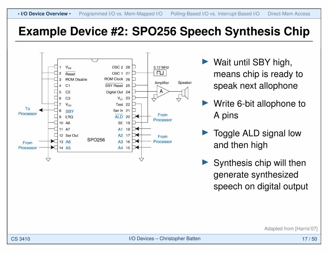
Example Device #2: SPO256 Speech Synthesis Chip
I Wait until SBY high,means chip is ready tospeak next allophone
I Write 6-bit allophone toA pins
I Toggle ALD signal lowand then high
I Synthesis chip will thengenerate synthesizedspeech on digital output
Adapted from [Harris’07]
CS 3410 I/O Devices – Christopher Batten 17 / 50
• I/O Device Overview • Programmed I/O vs. Mem-Mapped I/O Polling-Based I/O vs. Interrupt-Based I/O Direct-Mem Access
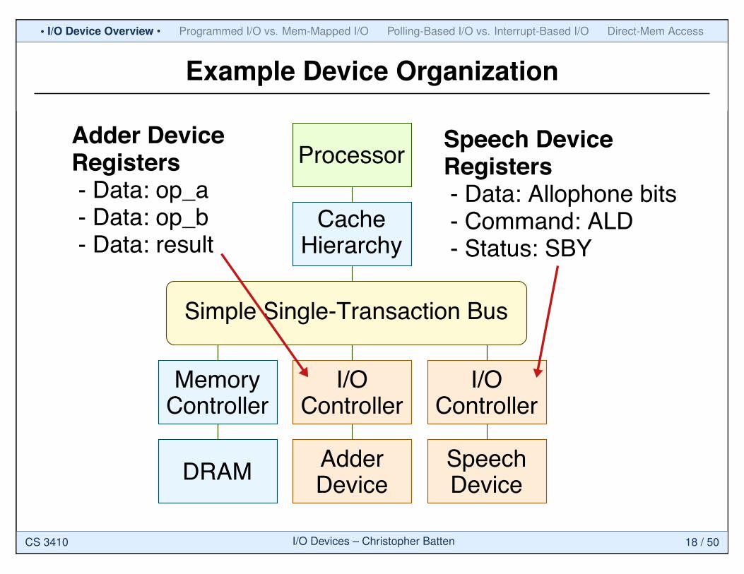
Example Device Organization
Processor
CacheHierarchy
I/OController
I/OController
Simple Single-Transaction Bus
DRAM
MemoryController
AdderDevice
SpeechDevice
Adder DeviceRegisters - Data: op_a - Data: op_b - Data: result
Speech DeviceRegisters - Data: Allophone bits - Command: ALD - Status: SBY
CS 3410 I/O Devices – Christopher Batten 18 / 50
• I/O Device Overview • Programmed I/O vs. Mem-Mapped I/O Polling-Based I/O vs. Interrupt-Based I/O Direct-Mem Access
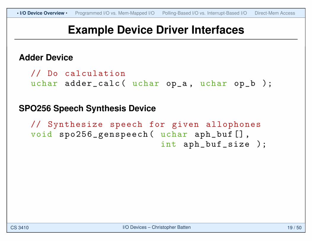
Example Device Driver Interfaces
Adder Device
// Do calculationuchar adder_calc( uchar op_a , uchar op_b );
SPO256 Speech Synthesis Device
// Synthesize speech for given allophonesvoid spo256_genspeech( uchar aph_buf[],
int aph_buf_size );
CS 3410 I/O Devices – Christopher Batten 19 / 50
I/O Device Overview • Programmed I/O vs. Mem-Mapped I/O • Polling-Based I/O vs. Interrupt-Based I/O Direct-Mem Access
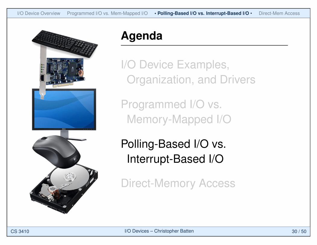
Agenda
I/O Device Examples,Organization, and Drivers
Programmed I/O vs.Memory-Mapped I/O
Polling-Based I/O vs.Interrupt-Based I/O
Direct-Memory Access
CS 3410 I/O Devices – Christopher Batten 20 / 50
I/O Device Overview • Programmed I/O vs. Mem-Mapped I/O • Polling-Based I/O vs. Interrupt-Based I/O Direct-Mem Access
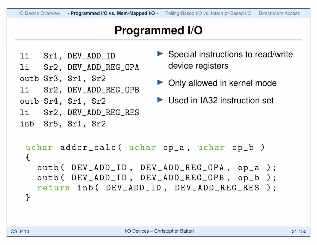
Programmed I/O
li $r1, DEV_ADD_ID
li $r2, DEV_ADD_REG_OPA
outb $r3, $r1, $r2
li $r2, DEV_ADD_REG_OPB
outb $r4, $r1, $r2
li $r2, DEV_ADD_REG_RES
inb $r5, $r1, $r2
I Special instructions to read/writedevice registers
I Only allowed in kernel mode
I Used in IA32 instruction set
uchar adder_calc( uchar op_a , uchar op_b ){
outb( DEV_ADD_ID , DEV_ADD_REG_OPA , op_a );outb( DEV_ADD_ID , DEV_ADD_REG_OPB , op_b );return inb( DEV_ADD_ID , DEV_ADD_REG_RES );
}
CS 3410 I/O Devices – Christopher Batten 21 / 50
I/O Device Overview • Programmed I/O vs. Mem-Mapped I/O • Polling-Based I/O vs. Interrupt-Based I/O Direct-Mem Access
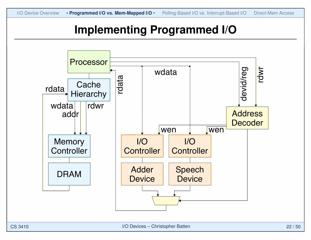
Implementing Programmed I/O
Processor
CacheHierarchy
I/OController
I/OController
DRAM
MemoryController
AdderDevice
SpeechDevice
rdwraddr
wdataAddressDecoder
rdata
wen wen
wdata
rdwr
devid/reg
rdata
CS 3410 I/O Devices – Christopher Batten 22 / 50
I/O Device Overview • Programmed I/O vs. Mem-Mapped I/O • Polling-Based I/O vs. Interrupt-Based I/O Direct-Mem Access
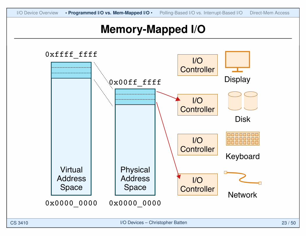
Memory-Mapped I/O
0xffff_ffff
0x0000_0000
VirtualAddressSpace
0x00ff_ffff
0x0000_0000
PhysicalAddressSpace
Display
Disk
Keyboard
Network
I/OController
I/OController
I/OController
I/OController
CS 3410 I/O Devices – Christopher Batten 23 / 50
I/O Device Overview • Programmed I/O vs. Mem-Mapped I/O • Polling-Based I/O vs. Interrupt-Based I/O Direct-Mem Access
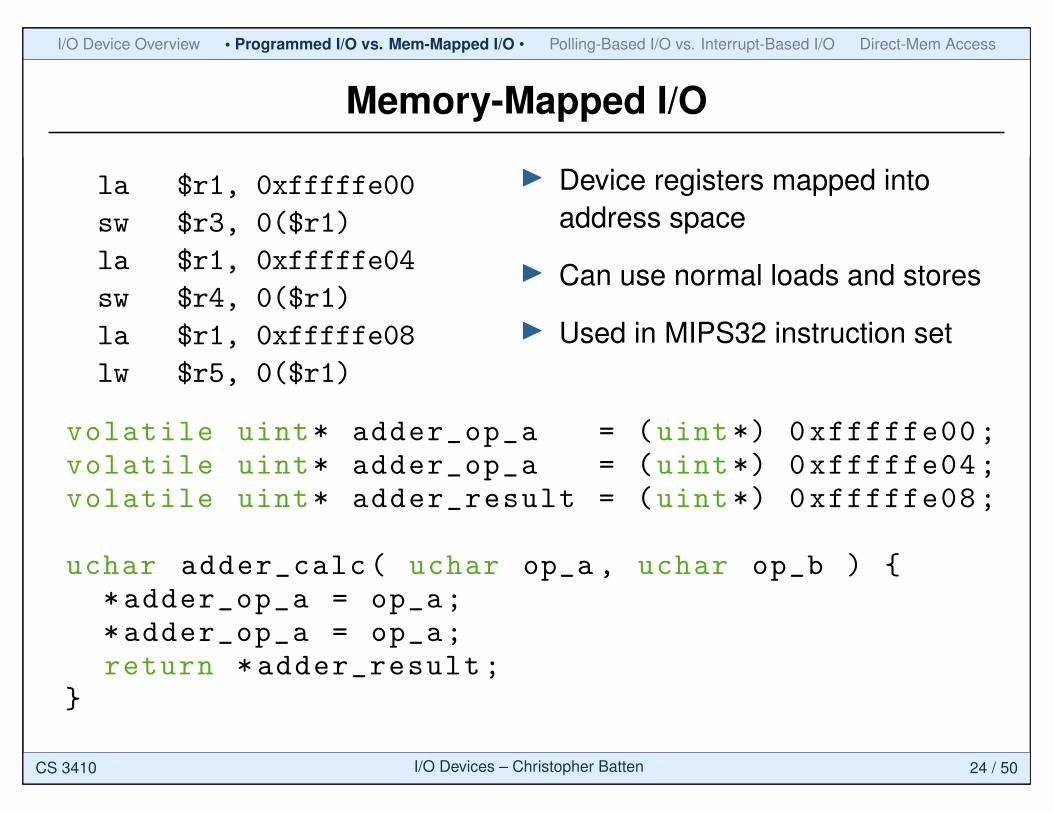
Memory-Mapped I/O
la $r1, 0xfffffe00
sw $r3, 0($r1)
la $r1, 0xfffffe04
sw $r4, 0($r1)
la $r1, 0xfffffe08
lw $r5, 0($r1)
I Device registers mapped intoaddress space
I Can use normal loads and stores
I Used in MIPS32 instruction set
volatile uint* adder_op_a = (uint*) 0xfffffe00;volatile uint* adder_op_a = (uint*) 0xfffffe04;volatile uint* adder_result = (uint*) 0xfffffe08;
uchar adder_calc( uchar op_a , uchar op_b ) {*adder_op_a = op_a;*adder_op_a = op_a;return *adder_result;
}
CS 3410 I/O Devices – Christopher Batten 24 / 50
I/O Device Overview • Programmed I/O vs. Mem-Mapped I/O • Polling-Based I/O vs. Interrupt-Based I/O Direct-Mem Access
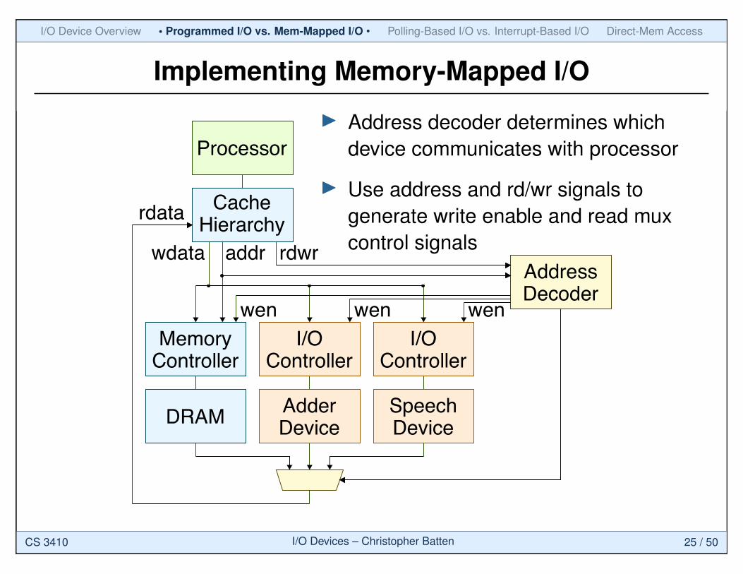
Implementing Memory-Mapped I/O
Processor
CacheHierarchy
I/OController
I/OController
DRAM
MemoryController
AdderDevice
SpeechDevice
rdwraddrwdataAddressDecoder
rdata
wen wen wen
I Address decoder determines whichdevice communicates with processor
I Use address and rd/wr signals togenerate write enable and read muxcontrol signals
CS 3410 I/O Devices – Christopher Batten 25 / 50
I/O Device Overview • Programmed I/O vs. Mem-Mapped I/O • Polling-Based I/O vs. Interrupt-Based I/O Direct-Mem Access
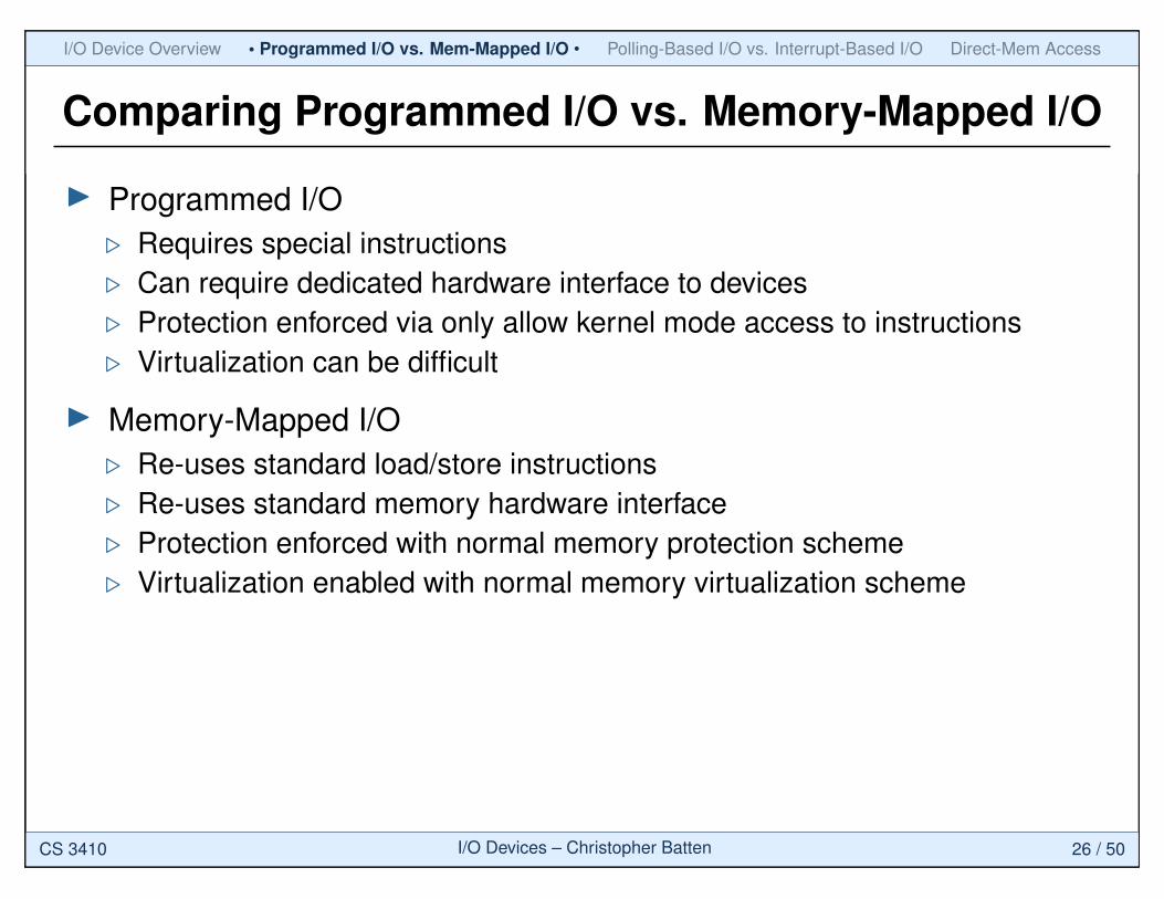
Comparing Programmed I/O vs. Memory-Mapped I/O
I Programmed I/O. Requires special instructions. Can require dedicated hardware interface to devices. Protection enforced via only allow kernel mode access to instructions. Virtualization can be difficult
I Memory-Mapped I/O. Re-uses standard load/store instructions. Re-uses standard memory hardware interface. Protection enforced with normal memory protection scheme. Virtualization enabled with normal memory virtualization scheme
CS 3410 I/O Devices – Christopher Batten 26 / 50
I/O Device Overview • Programmed I/O vs. Mem-Mapped I/O • Polling-Based I/O vs. Interrupt-Based I/O Direct-Mem Access
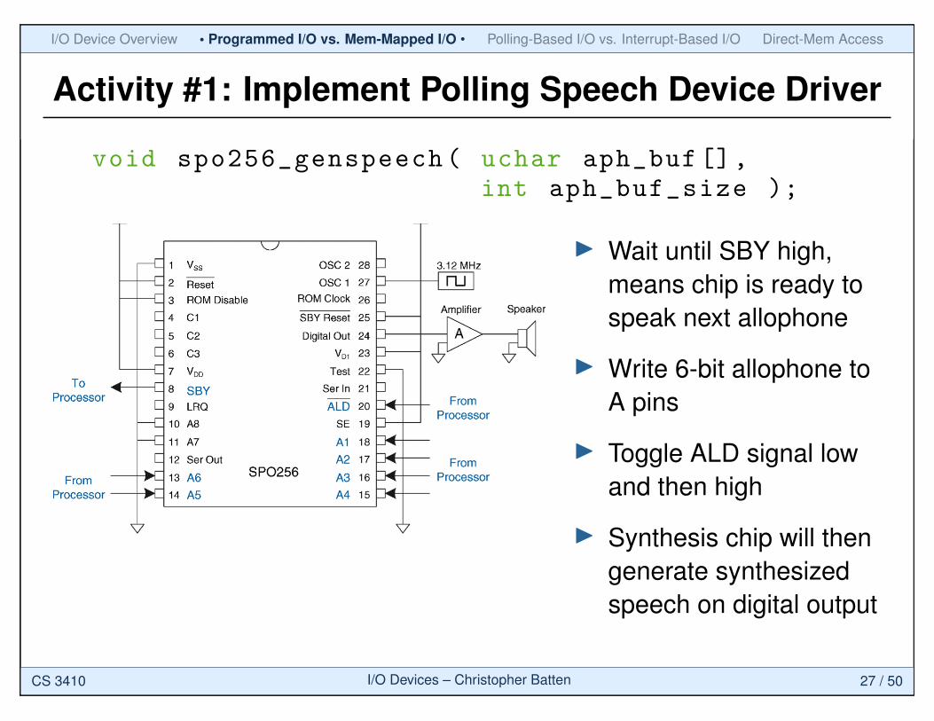
Activity #1: Implement Polling Speech Device Driver
void spo256_genspeech( uchar aph_buf[],int aph_buf_size );
I Wait until SBY high,means chip is ready tospeak next allophone
I Write 6-bit allophone toA pins
I Toggle ALD signal lowand then high
I Synthesis chip will thengenerate synthesizedspeech on digital output
CS 3410 I/O Devices – Christopher Batten 27 / 50
I/O Device Overview • Programmed I/O vs. Mem-Mapped I/O • Polling-Based I/O vs. Interrupt-Based I/O Direct-Mem Access
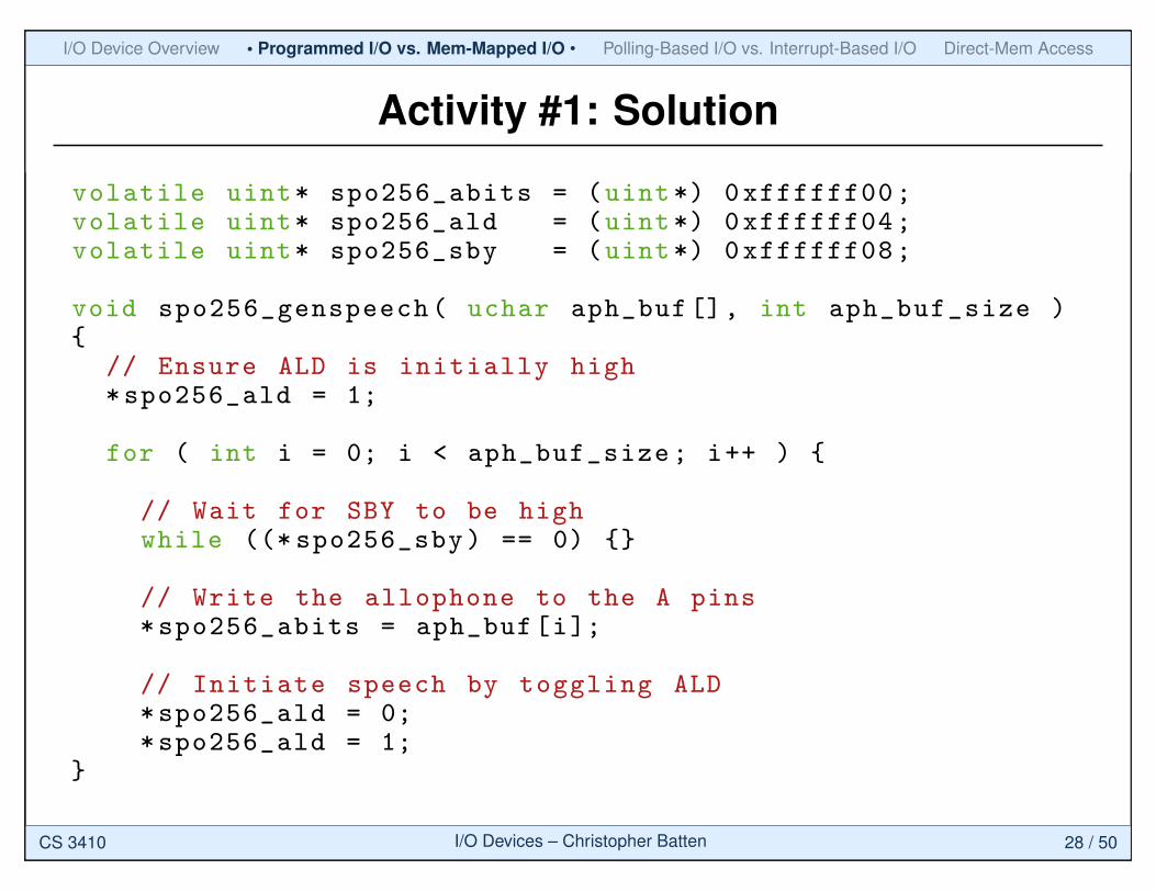
Activity #1: Solution
volatile uint* spo256_abits = (uint*) 0xffffff00;volatile uint* spo256_ald = (uint*) 0xffffff04;volatile uint* spo256_sby = (uint*) 0xffffff08;
void spo256_genspeech( uchar aph_buf[], int aph_buf_size ){
// Ensure ALD is initially high*spo256_ald = 1;
for ( int i = 0; i < aph_buf_size; i++ ) {
// Wait for SBY to be highwhile ((* spo256_sby) == 0) {}
// Write the allophone to the A pins*spo256_abits = aph_buf[i];
// Initiate speech by toggling ALD*spo256_ald = 0;*spo256_ald = 1;
}
CS 3410 I/O Devices – Christopher Batten 28 / 50
I/O Device Overview • Programmed I/O vs. Mem-Mapped I/O • Polling-Based I/O vs. Interrupt-Based I/O Direct-Mem Access
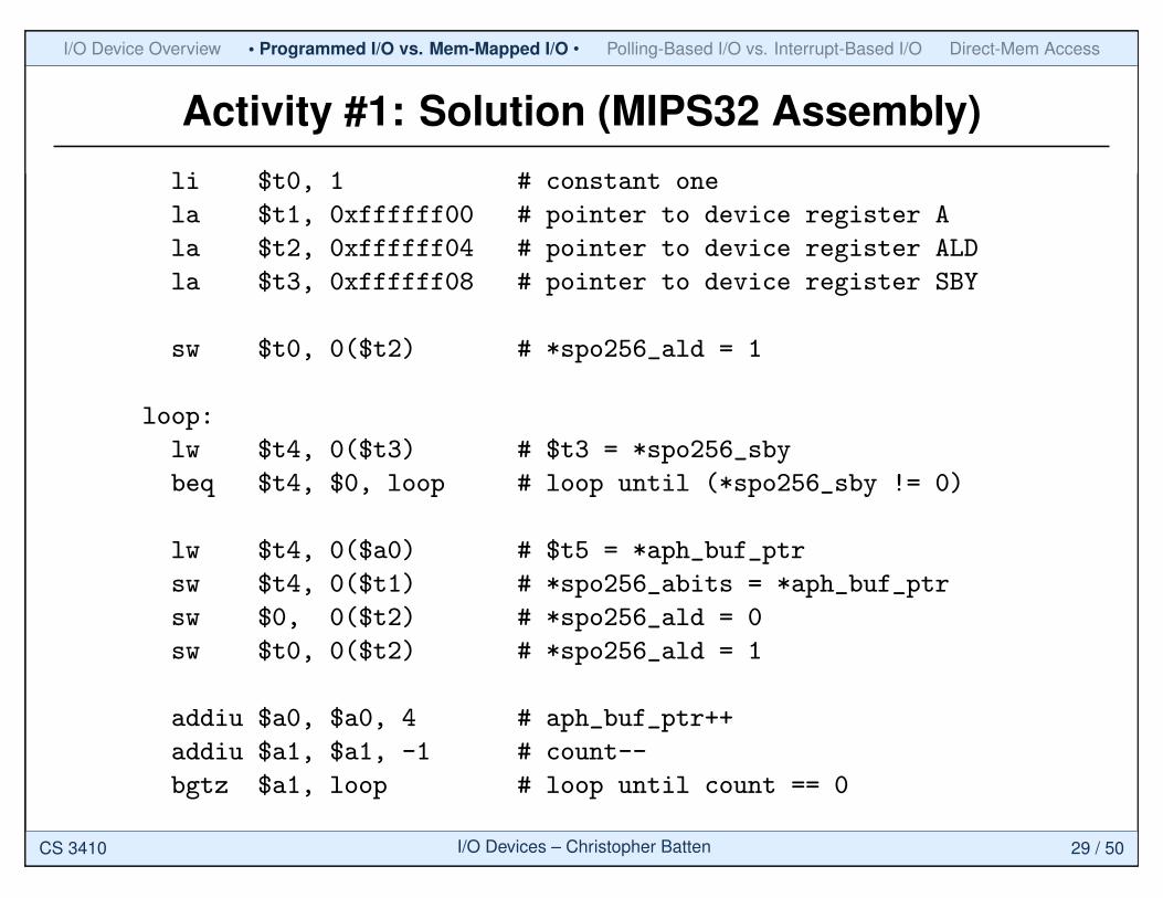
Activity #1: Solution (MIPS32 Assembly)li $t0, 1 # constant one
la $t1, 0xffffff00 # pointer to device register A
la $t2, 0xffffff04 # pointer to device register ALD
la $t3, 0xffffff08 # pointer to device register SBY
sw $t0, 0($t2) # *spo256_ald = 1
loop:
lw $t4, 0($t3) # $t3 = *spo256_sby
beq $t4, $0, loop # loop until (*spo256_sby != 0)
lw $t4, 0($a0) # $t5 = *aph_buf_ptr
sw $t4, 0($t1) # *spo256_abits = *aph_buf_ptr
sw $0, 0($t2) # *spo256_ald = 0
sw $t0, 0($t2) # *spo256_ald = 1
addiu $a0, $a0, 4 # aph_buf_ptr++
addiu $a1, $a1, -1 # count--
bgtz $a1, loop # loop until count == 0
CS 3410 I/O Devices – Christopher Batten 29 / 50
I/O Device Overview Programmed I/O vs. Mem-Mapped I/O • Polling-Based I/O vs. Interrupt-Based I/O • Direct-Mem Access
Agenda
I/O Device Examples,Organization, and Drivers
Programmed I/O vs.Memory-Mapped I/O
Polling-Based I/O vs.Interrupt-Based I/O
Direct-Memory Access
CS 3410 I/O Devices – Christopher Batten 30 / 50
I/O Device Overview Programmed I/O vs. Mem-Mapped I/O • Polling-Based I/O vs. Interrupt-Based I/O • Direct-Mem Access
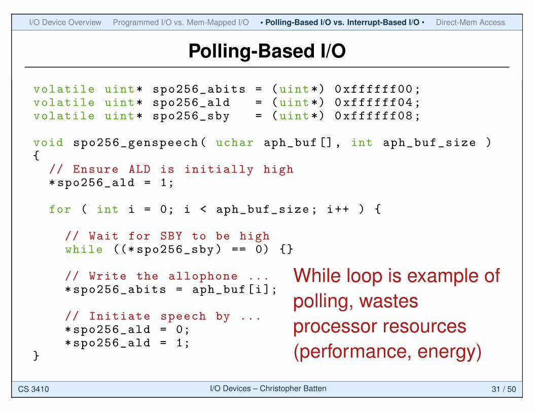
Polling-Based I/O
volatile uint* spo256_abits = (uint*) 0xffffff00;volatile uint* spo256_ald = (uint*) 0xffffff04;volatile uint* spo256_sby = (uint*) 0xffffff08;
void spo256_genspeech( uchar aph_buf[], int aph_buf_size ){
// Ensure ALD is initially high*spo256_ald = 1;
for ( int i = 0; i < aph_buf_size; i++ ) {
// Wait for SBY to be highwhile ((* spo256_sby) == 0) {}
// Write the allophone ...*spo256_abits = aph_buf[i];
// Initiate speech by ...*spo256_ald = 0;*spo256_ald = 1;
}
While loop is example ofpolling, wastesprocessor resources(performance, energy)
CS 3410 I/O Devices – Christopher Batten 31 / 50
I/O Device Overview Programmed I/O vs. Mem-Mapped I/O • Polling-Based I/O vs. Interrupt-Based I/O • Direct-Mem Access
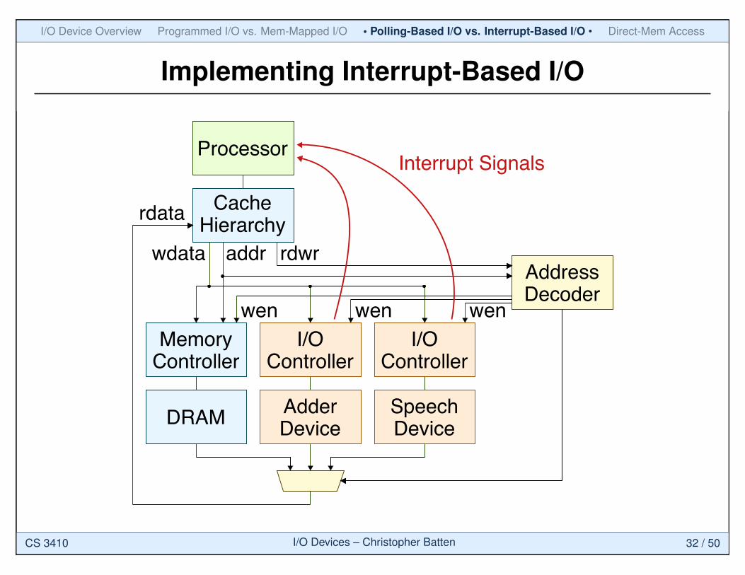
Implementing Interrupt-Based I/O
Processor
CacheHierarchy
I/OController
I/OController
DRAM
MemoryController
AdderDevice
SpeechDevice
rdwraddrwdataAddressDecoder
rdata
wen wen wen
Interrupt Signals
CS 3410 I/O Devices – Christopher Batten 32 / 50
I/O Device Overview Programmed I/O vs. Mem-Mapped I/O • Polling-Based I/O vs. Interrupt-Based I/O • Direct-Mem Access
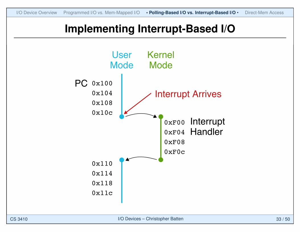
Implementing Interrupt-Based I/O
0x100
0x104
0x108
0x10c
0x110
0x114
0x118
0x11c
0xF00
0xF04
0xF08
0xF0c
Interrupt Arrives
UserMode
PC
InterruptHandler
KernelMode
CS 3410 I/O Devices – Christopher Batten 33 / 50
I/O Device Overview Programmed I/O vs. Mem-Mapped I/O • Polling-Based I/O vs. Interrupt-Based I/O • Direct-Mem Access
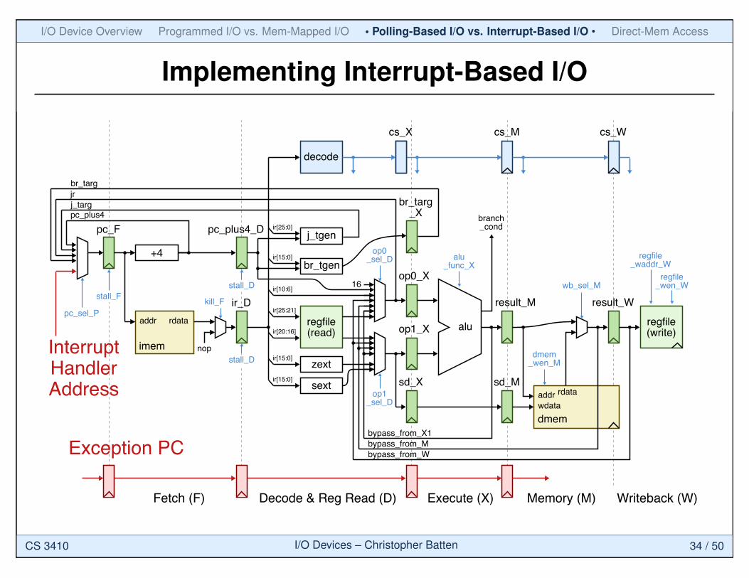
Implementing Interrupt-Based I/O
zext
sext
ir[20:16]
ir[25:21]
ir[15:0]
ir[15:0]
ir[25:0]
ir[15:0]
j_tgen
br_tgen
ir[10:6]16
op0_X
pc_plus4_D
op1_X
sd_X sd_M
result_Mir_D
cs_X cs_M cs_W
pc_F
pc_plus4
br_targ
j_targjr
bypass_from_X1
bypass_from_M
bypass_from_W
imem
dmem
+4
addr
wdata
rdata
result_W
regfile(read)
regfile(write)
addr rdata
nop
decode
alu
kill_F
pc_sel_P
op0_sel_D
op1_sel_D
dmem_wen_M
alu_func_X
wb_sel_Mregfile
_wen_W
regfile_waddr_W
branch_cond
Fetch (F) Decode & Reg Read (D) Execute (X) Memory (M) Writeback (W)
stall_F
stall_D
stall_D
br_targ_X
InterruptHandlerAddress
Exception PC
CS 3410 I/O Devices – Christopher Batten 34 / 50
I/O Device Overview Programmed I/O vs. Mem-Mapped I/O • Polling-Based I/O vs. Interrupt-Based I/O • Direct-Mem Access
Comparing Polling-Based I/O vs. Interrupt-Based I/O
I Polling-Based I/O. Simple to implement. Predictable performance helpful for real-time applications. Can consume significant performance and energy resources while waiting
I Interrupt-Based I/O. More complicated to implement. More efficient in most cases
CS 3410 I/O Devices – Christopher Batten 35 / 50
I/O Device Overview Programmed I/O vs. Mem-Mapped I/O • Polling-Based I/O vs. Interrupt-Based I/O • Direct-Mem Access
Activity #2: Implement Interrupt Speech Device Driver
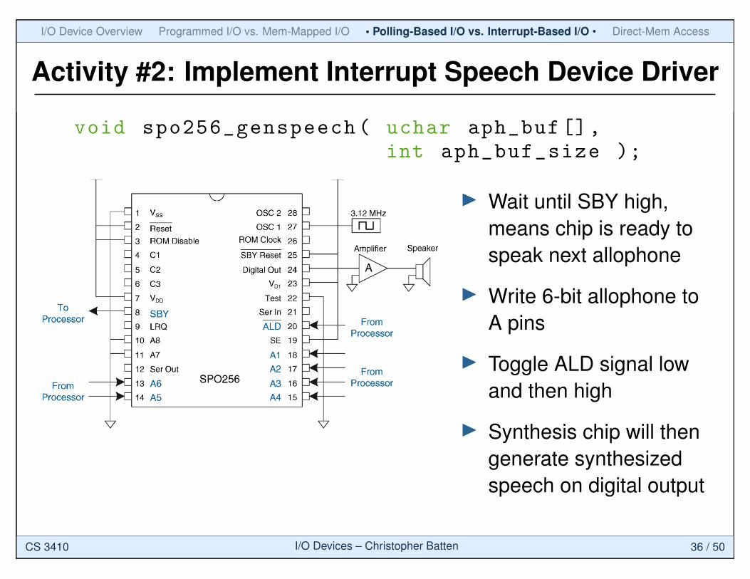
void spo256_genspeech( uchar aph_buf[],int aph_buf_size );
I Wait until SBY high,means chip is ready tospeak next allophone
I Write 6-bit allophone toA pins
I Toggle ALD signal lowand then high
I Synthesis chip will thengenerate synthesizedspeech on digital output
CS 3410 I/O Devices – Christopher Batten 36 / 50
I/O Device Overview Programmed I/O vs. Mem-Mapped I/O • Polling-Based I/O vs. Interrupt-Based I/O • Direct-Mem Access
Activity #2: Solution (genspeech function)
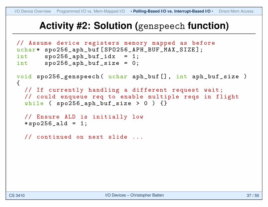
// Assume device registers memory mapped as beforeuchar* spo256_aph_buf[SPO256_APH_BUF_MAX_SIZE ];int spo256_aph_buf_idx = 1;int spo256_aph_buf_size = 0;
void spo256_genspeech( uchar aph_buf[], int aph_buf_size ){
// If currently handling a different request wait;// could enqueue req to enable multiple reqs in flightwhile ( spo256_aph_buf_size > 0 ) {}
// Ensure ALD is initially low*spo256_ald = 1;
// continued on next slide ...
CS 3410 I/O Devices – Christopher Batten 37 / 50
I/O Device Overview Programmed I/O vs. Mem-Mapped I/O • Polling-Based I/O vs. Interrupt-Based I/O • Direct-Mem Access
Activity #2: Solution (genspeech function)
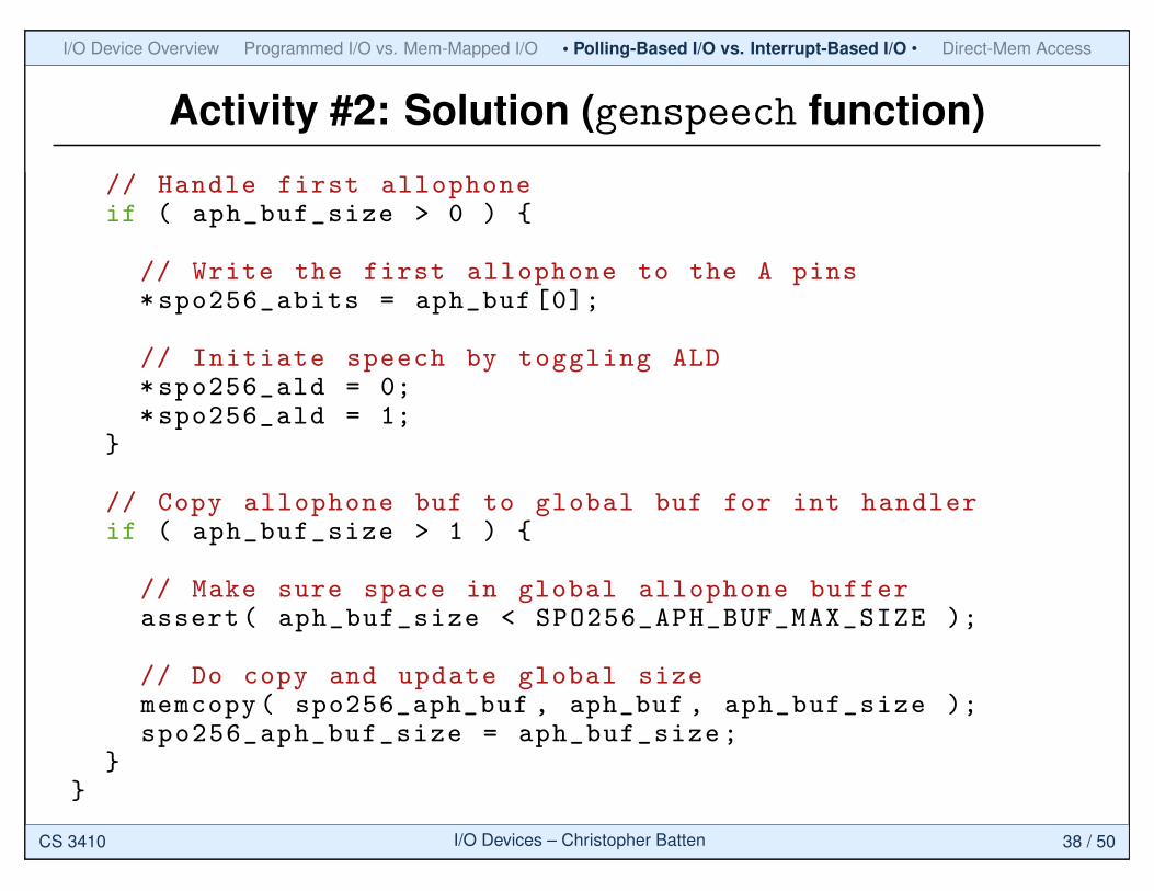
// Handle first allophoneif ( aph_buf_size > 0 ) {
// Write the first allophone to the A pins*spo256_abits = aph_buf [0];
// Initiate speech by toggling ALD*spo256_ald = 0;*spo256_ald = 1;
}
// Copy allophone buf to global buf for int handlerif ( aph_buf_size > 1 ) {
// Make sure space in global allophone bufferassert( aph_buf_size < SPO256_APH_BUF_MAX_SIZE );
// Do copy and update global sizememcopy( spo256_aph_buf , aph_buf , aph_buf_size );spo256_aph_buf_size = aph_buf_size;
}}
CS 3410 I/O Devices – Christopher Batten 38 / 50
I/O Device Overview Programmed I/O vs. Mem-Mapped I/O • Polling-Based I/O vs. Interrupt-Based I/O • Direct-Mem Access
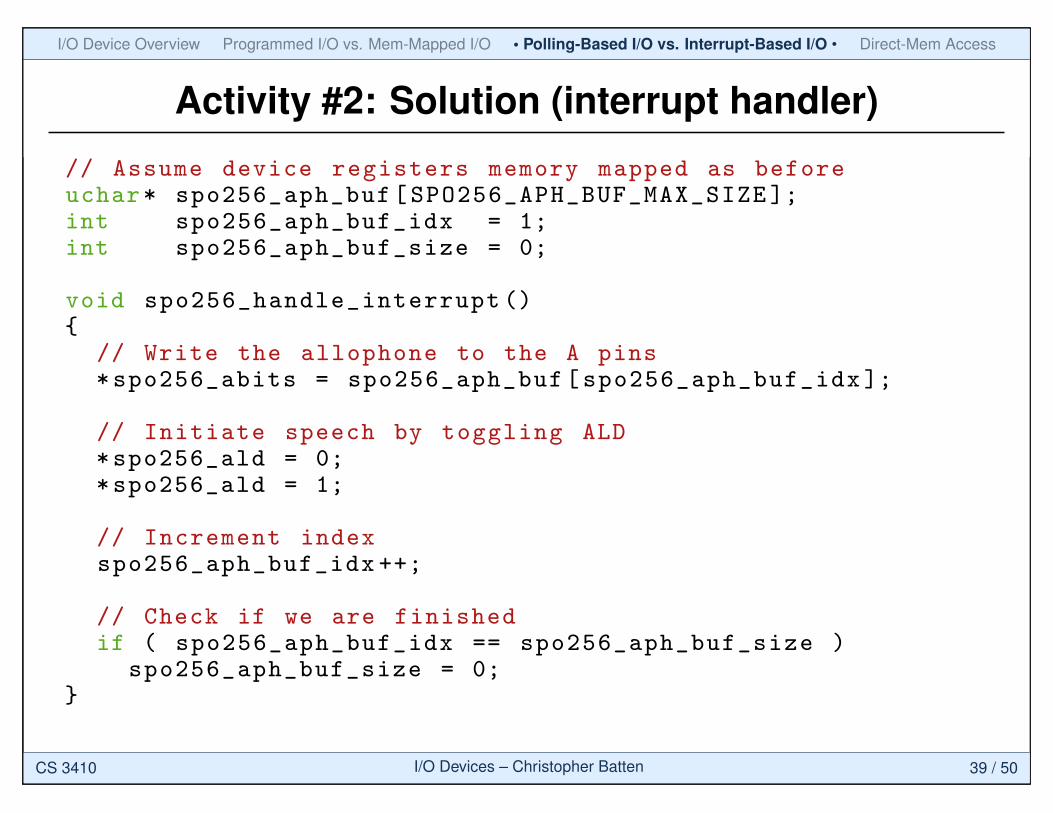
Activity #2: Solution (interrupt handler)
// Assume device registers memory mapped as beforeuchar* spo256_aph_buf[SPO256_APH_BUF_MAX_SIZE ];int spo256_aph_buf_idx = 1;int spo256_aph_buf_size = 0;
void spo256_handle_interrupt (){
// Write the allophone to the A pins*spo256_abits = spo256_aph_buf[spo256_aph_buf_idx ];
// Initiate speech by toggling ALD*spo256_ald = 0;*spo256_ald = 1;
// Increment indexspo256_aph_buf_idx ++;
// Check if we are finishedif ( spo256_aph_buf_idx == spo256_aph_buf_size )
spo256_aph_buf_size = 0;}
CS 3410 I/O Devices – Christopher Batten 39 / 50
I/O Device Overview Programmed I/O vs. Mem-Mapped I/O Polling-Based I/O vs. Interrupt-Based I/O • Direct-Mem Access •
Agenda
I/O Device Examples,Organization, and Drivers
Programmed I/O vs.Memory-Mapped I/O
Polling-Based I/O vs.Interrupt-Based I/O
Direct-Memory Access
CS 3410 I/O Devices – Christopher Batten 40 / 50
I/O Device Overview Programmed I/O vs. Mem-Mapped I/O Polling-Based I/O vs. Interrupt-Based I/O • Direct-Mem Access •
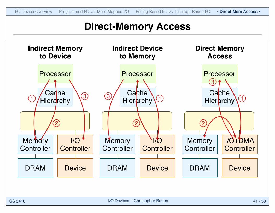
Direct-Memory Access
Processor
CacheHierarchy
I/OController
DRAM
MemoryController
Device
1
Indirect Memoryto Device
2
3
Processor
CacheHierarchy
I/OController
DRAM
MemoryController
Device
1
Indirect Deviceto Memory
2
3
Processor
CacheHierarchy
I/O+DMAController
DRAM
MemoryController
Device
1
Direct MemoryAccess
2
3
CS 3410 I/O Devices – Christopher Batten 41 / 50
I/O Device Overview Programmed I/O vs. Mem-Mapped I/O Polling-Based I/O vs. Interrupt-Based I/O • Direct-Mem Access •
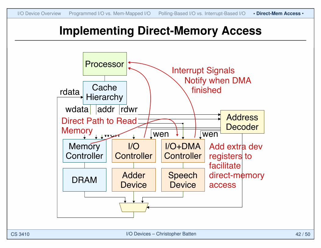
Implementing Direct-Memory Access
Processor
CacheHierarchy
I/OController
I/OController
DRAM
MemoryController
AdderDevice
SpeechDevice
rdwraddrwdataAddressDecoder
rdata
wen wen wen
Interrupt Signals
Add extra dev registers tofacilitatedirect-memoryaccess
I/O+DMAController
Direct Path to ReadMemory
Notify when DMA finished
CS 3410 I/O Devices – Christopher Batten 42 / 50
I/O Device Overview Programmed I/O vs. Mem-Mapped I/O Polling-Based I/O vs. Interrupt-Based I/O • Direct-Mem Access •
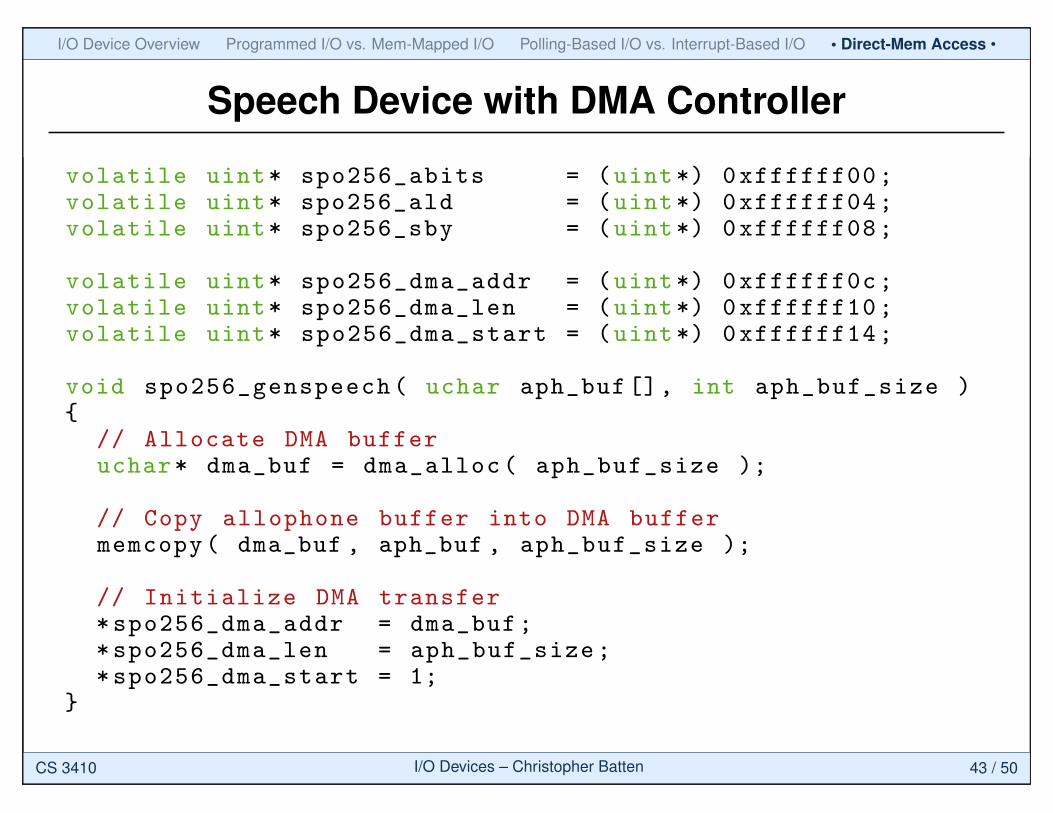
Speech Device with DMA Controller
volatile uint* spo256_abits = (uint*) 0xffffff00;volatile uint* spo256_ald = (uint*) 0xffffff04;volatile uint* spo256_sby = (uint*) 0xffffff08;
volatile uint* spo256_dma_addr = (uint*) 0xffffff0c;volatile uint* spo256_dma_len = (uint*) 0xffffff10;volatile uint* spo256_dma_start = (uint*) 0xffffff14;
void spo256_genspeech( uchar aph_buf[], int aph_buf_size ){
// Allocate DMA bufferuchar* dma_buf = dma_alloc( aph_buf_size );
// Copy allophone buffer into DMA buffermemcopy( dma_buf , aph_buf , aph_buf_size );
// Initialize DMA transfer*spo256_dma_addr = dma_buf;*spo256_dma_len = aph_buf_size;*spo256_dma_start = 1;
}
CS 3410 I/O Devices – Christopher Batten 43 / 50
I/O Device Overview Programmed I/O vs. Mem-Mapped I/O Polling-Based I/O vs. Interrupt-Based I/O • Direct-Mem Access •
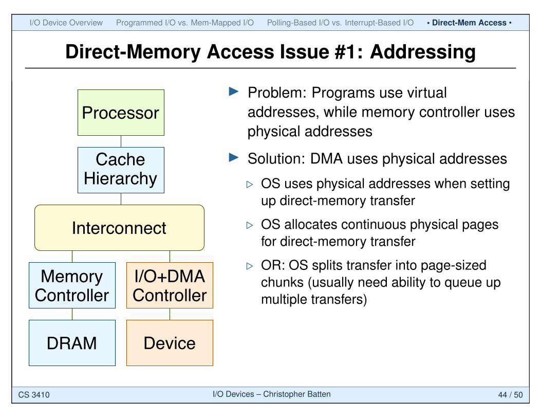
Direct-Memory Access Issue #1: Addressing
Processor
CacheHierarchy
I/O+DMAController
DRAM
MemoryController
Device
Interconnect
I Problem: Programs use virtualaddresses, while memory controller usesphysical addresses
I Solution: DMA uses physical addresses
. OS uses physical addresses when settingup direct-memory transfer
. OS allocates continuous physical pagesfor direct-memory transfer
. OR: OS splits transfer into page-sizedchunks (usually need ability to queue upmultiple transfers)
CS 3410 I/O Devices – Christopher Batten 44 / 50
I/O Device Overview Programmed I/O vs. Mem-Mapped I/O Polling-Based I/O vs. Interrupt-Based I/O • Direct-Mem Access •
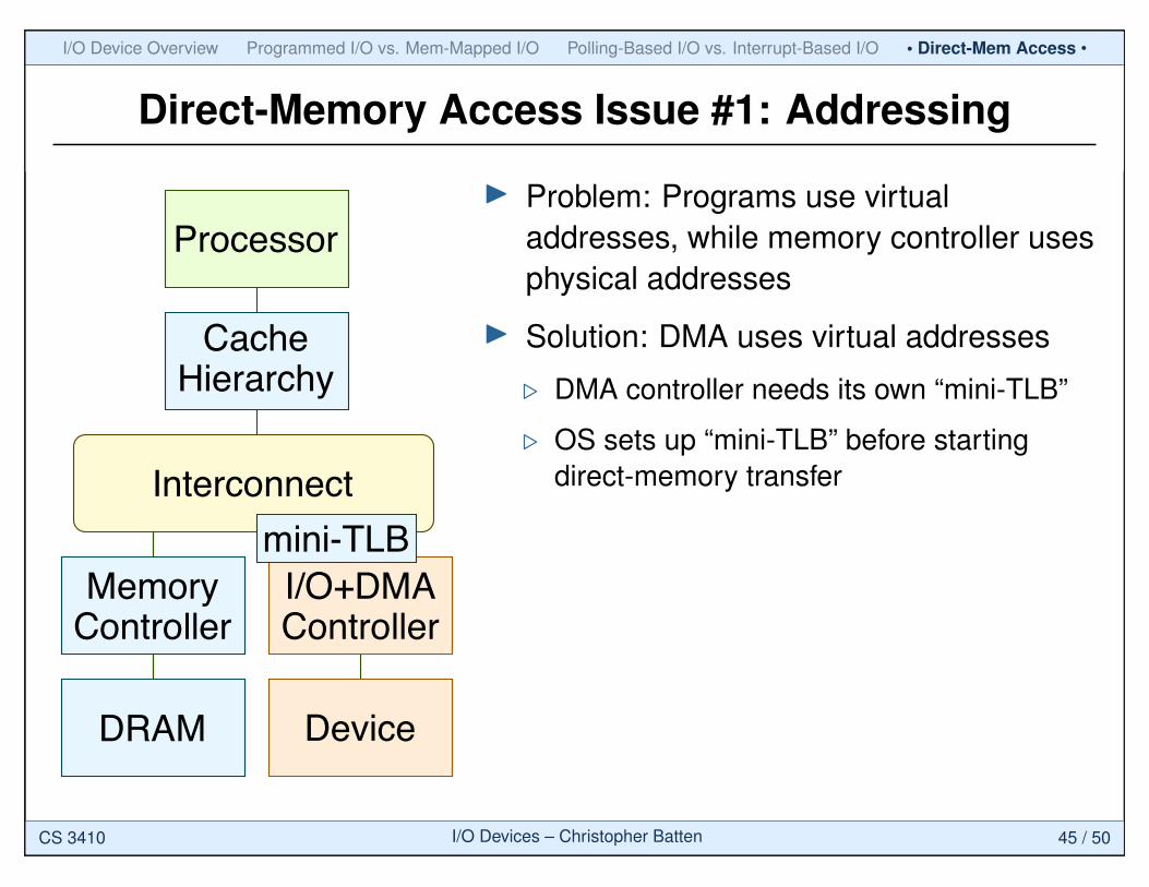
Direct-Memory Access Issue #1: Addressing
Processor
CacheHierarchy
I/O+DMAController
DRAM
MemoryController
Device
Interconnect
mini-TLB
I Problem: Programs use virtualaddresses, while memory controller usesphysical addresses
I Solution: DMA uses virtual addresses
. DMA controller needs its own “mini-TLB”
. OS sets up “mini-TLB” before startingdirect-memory transfer
CS 3410 I/O Devices – Christopher Batten 45 / 50
I/O Device Overview Programmed I/O vs. Mem-Mapped I/O Polling-Based I/O vs. Interrupt-Based I/O • Direct-Mem Access •
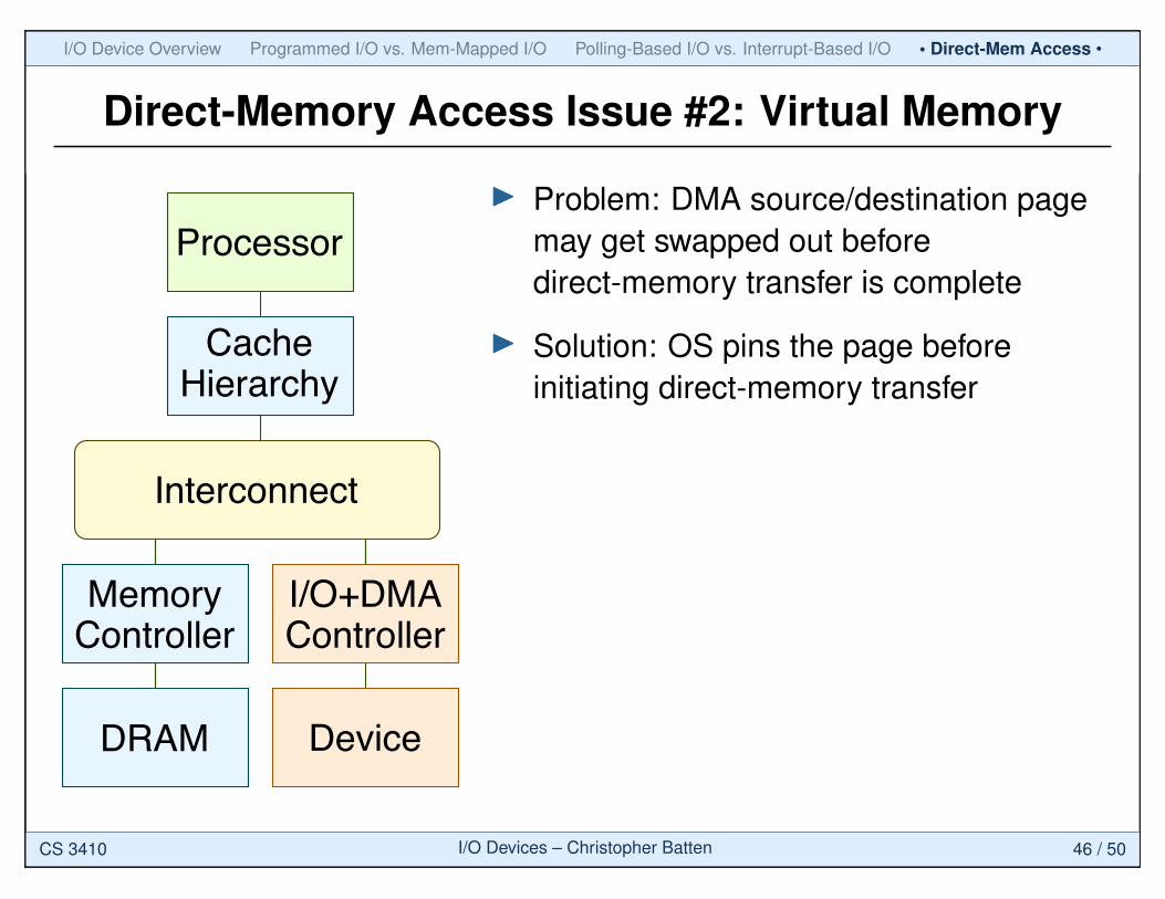
Direct-Memory Access Issue #2: Virtual Memory
Processor
CacheHierarchy
I/O+DMAController
DRAM
MemoryController
Device
Interconnect
I Problem: DMA source/destination pagemay get swapped out beforedirect-memory transfer is complete
I Solution: OS pins the page beforeinitiating direct-memory transfer
CS 3410 I/O Devices – Christopher Batten 46 / 50
I/O Device Overview Programmed I/O vs. Mem-Mapped I/O Polling-Based I/O vs. Interrupt-Based I/O • Direct-Mem Access •
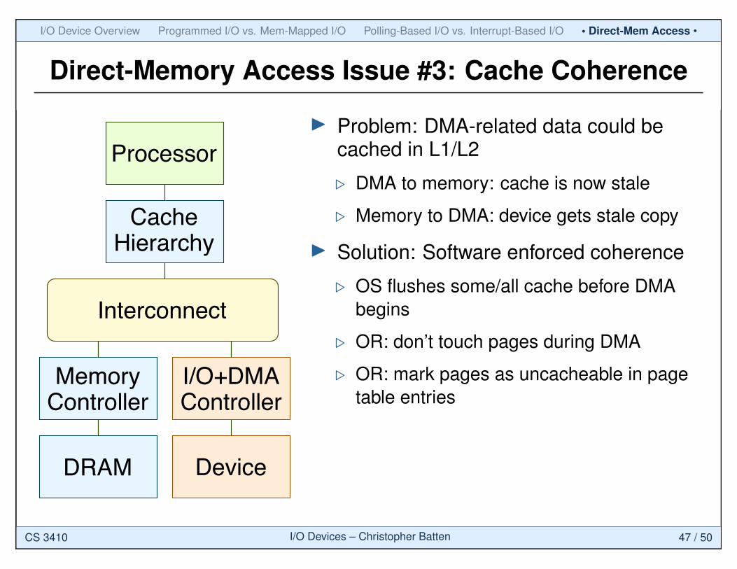
Direct-Memory Access Issue #3: Cache Coherence
Processor
CacheHierarchy
I/O+DMAController
DRAM
MemoryController
Device
Interconnect
I Problem: DMA-related data could becached in L1/L2
. DMA to memory: cache is now stale
. Memory to DMA: device gets stale copy
I Solution: Software enforced coherence
. OS flushes some/all cache before DMAbegins
. OR: don’t touch pages during DMA
. OR: mark pages as uncacheable in pagetable entries
CS 3410 I/O Devices – Christopher Batten 47 / 50
I/O Device Overview Programmed I/O vs. Mem-Mapped I/O Polling-Based I/O vs. Interrupt-Based I/O • Direct-Mem Access •
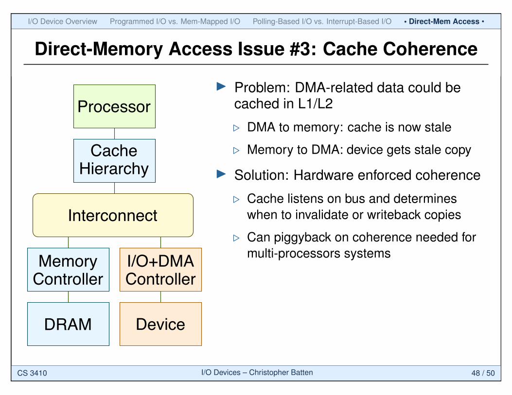
Direct-Memory Access Issue #3: Cache Coherence
Processor
CacheHierarchy
I/O+DMAController
DRAM
MemoryController
Device
Interconnect
I Problem: DMA-related data could becached in L1/L2
. DMA to memory: cache is now stale
. Memory to DMA: device gets stale copy
I Solution: Hardware enforced coherence
. Cache listens on bus and determineswhen to invalidate or writeback copies
. Can piggyback on coherence needed formulti-processors systems
CS 3410 I/O Devices – Christopher Batten 48 / 50
I/O Device Overview Programmed I/O vs. Mem-Mapped I/O Polling-Based I/O vs. Interrupt-Based I/O Direct-Mem Access
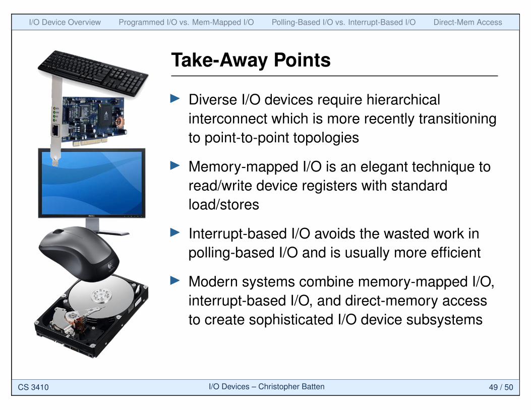
Take-Away Points
I Diverse I/O devices require hierarchicalinterconnect which is more recently transitioningto point-to-point topologies
I Memory-mapped I/O is an elegant technique toread/write device registers with standardload/stores
I Interrupt-based I/O avoids the wasted work inpolling-based I/O and is usually more efficient
I Modern systems combine memory-mapped I/O,interrupt-based I/O, and direct-memory accessto create sophisticated I/O device subsystems
CS 3410 I/O Devices – Christopher Batten 49 / 50
I/O Device Overview Programmed I/O vs. Mem-Mapped I/O Polling-Based I/O vs. Interrupt-Based I/O Direct-Mem Access
Acknowledgments
I [Corbet’05] J. Corbet, A. Rubini, and G. Kroah-Hartman, “Linux DeviceDrivers,” 3rd ed, O’Reilly Media, 2005.
I [Harris’07] D. Harris and S. Harris, “Digital Design and ComputerArchitecture,” Morgan Kaufmann, 2007.
I [Patterson’08] D.A. Patterson and J.L. Hennessy, “ComputerOrganization and Design: The Hardware/Software Interface,” 4th ed,Morgan Kaufmann, 2008.
CS 3410 I/O Devices – Christopher Batten 50 / 50


![Hakim Weatherspoon CS 3410€¦ · Pipelining Hakim Weatherspoon CS 3410. Computer Science. Cornell University [Weatherspoon, Bala, Bracy, McKee, and Sirer]](https://img.pdfslide.us/doc/110x75/5fbd449b51dd8d4ba4394cd5/hakim-weatherspoon-cs-pipelining-hakim-weatherspoon-cs-3410-computer-science-cornell.jpg)


![Hakim Weatherspoon CS 3410 · 2020-01-08 · Calling Conventions Hakim Weatherspoon CS 3410. Computer Science. Cornell University [Weatherspoon, Bala, Bracy, McKee and Sirer]](https://img.pdfslide.us/doc/110x75/5f96a8e542e1ef67bd47302f/hakim-weatherspoon-cs-2020-01-08-calling-conventions-hakim-weatherspoon-cs-3410.jpg)