Embed Size (px)
Citation preview
GuardLogix™ Controller Systems(Catalog Numbers 1756-L61S, 1756-L62S, 1756-LSP)
Safety Reference Manual
Important User Information Solid state equipment has operational characteristics differing from those of electromechanical equipment. Safety Guidelines for the Application, Installation and Maintenance of Solid State Controls (Publication SGI-1.1 available from your local Rockwell Automation sales office or online at http://www.ab.com/manuals/gi) describes some important differences between solid state equipment and hard-wired electromechanical devices. Because of this difference, and also because of the wide variety of uses for solid state equipment, all persons responsible for applying this equipment must satisfy themselves that each intended application of this equipment is acceptable.
In no event will Rockwell Automation, Inc. be responsible or liable for indirect or consequential damages resulting from the use or application of this equipment.
The examples and diagrams in this manual are included solely for illustrative purposes. Because of the many variables and requirements associated with any particular installation, Rockwell Automation, Inc. cannot assume responsibility or liability for actual use based on the examples and diagrams.
No patent liability is assumed by Rockwell Automation, Inc. with respect to use of information, circuits, equipment, or software described in this manual.
Reproduction of the contents of this manual, in whole or in part, without written permission of Rockwell Automation, Inc. is prohibited.
Throughout this manual, when necessary we use notes to make you aware of safety considerations.
Allen-Bradley, ControlLogix, GuardLogix, RSLogix, RSNetWorx for DeviceNet, and RSLinx are trademarks of Rockwell Automation, Inc.
DeviceNet is a trademark of the Open DeviceNet Vendor Association.
Trademarks not belonging to Rockwell Automation are the property of their respective holders.
WARNINGIdentifies information about practices or circumstances that can cause an explosion in a hazardous environment, which may lead to personal injury or death, property damage, or economic loss.
IMPORTANT Identifies information that is critical for successful application and understanding of the product.
ATTENTION Identifies information about practices or circumstances that can lead to personal injury or death, property damage, or economic loss. Attentions help you:
• identify a hazard
• avoid a hazard
• recognize the consequence
Summary of Changes
The information below summarizes the changes to this manual since the last publication.
To help you find new and updated information in this release of the manual, we have included change bars as shown to the right of this paragraph.
For information about See
Using the standard task in SIL-2 safety applications 1-1
Where to find updated information on GuardLogix controller and DeviceNet Safety I/O certified series and firmware revisions
1-4
iii Publication 1756-RM093B-EN-P - October 2005

iv Summary of Changes
Publication 1756-RM093B-EN-P - October 2005
Table of Contents
PrefaceIntroduction . . . . . . . . . . . . . . . . . . . . . . . . . . . . . . . . . . . P-1Manual Set-Up . . . . . . . . . . . . . . . . . . . . . . . . . . . . . . . . . P-1Understanding Terminology . . . . . . . . . . . . . . . . . . . . . . . P-2
Related Documentation . . . . . . . . . . . . . . . . . . . . . . . . P-3
Chapter 1SIL Concept SIL 3 Certification . . . . . . . . . . . . . . . . . . . . . . . . . . . . . . . 1-1
Functional Verification Tests . . . . . . . . . . . . . . . . . . . . . . . 1-2GuardLogix Architecture for SIL 3 Applications. . . . . . . . . . 1-3GuardLogix System Components . . . . . . . . . . . . . . . . . . . . 1-4Safety Certifications and Compliances . . . . . . . . . . . . . . . . 1-5Agency Certifications. . . . . . . . . . . . . . . . . . . . . . . . . . . . . 1-6GuardLogix PFD and PFH Specifications . . . . . . . . . . . . . . 1-6
Definitions of PFD and PFH . . . . . . . . . . . . . . . . . . . . . 1-6PFD and PFH Calculations . . . . . . . . . . . . . . . . . . . . . . 1-7
SIL Compliance Distribution and Weight . . . . . . . . . . . . . . 1-8Safety Reaction Times . . . . . . . . . . . . . . . . . . . . . . . . . . . . 1-9
System Reaction Time . . . . . . . . . . . . . . . . . . . . . . . . . 1-9Safety Task Reaction Time . . . . . . . . . . . . . . . . . . . . . . 1-10Safety Task Period and Safety Task Watchdog. . . . . . . . 1-10
Contact Information When Device Failure Occurs. . . . . . . . 1-10
Chapter 2GuardLogix Controller System GuardLogix Controller Hardware . . . . . . . . . . . . . . . . . . . . 2-1
Primary Controller . . . . . . . . . . . . . . . . . . . . . . . . . . . . 2-1Safety Partner . . . . . . . . . . . . . . . . . . . . . . . . . . . . . . . 2-2
Safety I/O . . . . . . . . . . . . . . . . . . . . . . . . . . . . . . . . . . . . . 2-2Chassis . . . . . . . . . . . . . . . . . . . . . . . . . . . . . . . . . . . . . . . 2-2Power Supplies . . . . . . . . . . . . . . . . . . . . . . . . . . . . . . . . . 2-2CIP Safety Protocol . . . . . . . . . . . . . . . . . . . . . . . . . . . . . . 2-3Communication Bridges . . . . . . . . . . . . . . . . . . . . . . . . . . 2-3Programming Overview. . . . . . . . . . . . . . . . . . . . . . . . . . . 2-4
RSLogix 5000 Programming Software . . . . . . . . . . . . . . 2-4
Chapter 3DeviceNet Safety I/O for the GuardLogix Control System
Overview . . . . . . . . . . . . . . . . . . . . . . . . . . . . . . . . . . . . . 3-1Typical Safety Functions of DeviceNet Safety I/O Modules . 3-1
Safe State. . . . . . . . . . . . . . . . . . . . . . . . . . . . . . . . . . . 3-1Diagnostics . . . . . . . . . . . . . . . . . . . . . . . . . . . . . . . . . 3-1Status Data . . . . . . . . . . . . . . . . . . . . . . . . . . . . . . . . . 3-2Status LEDs . . . . . . . . . . . . . . . . . . . . . . . . . . . . . . . . . 3-2ON- or OFF-Delay Function . . . . . . . . . . . . . . . . . . . . . 3-2Input and Output Line Conditioning . . . . . . . . . . . . . . . 3-2I/O Module Connection Status . . . . . . . . . . . . . . . . . . . 3-3
v Publication 1756-RM093B-EN-P - October 2005
Table of Contents vi
How to Latch and Reset Faulted I/O. . . . . . . . . . . . . . . 3-3Reaction Time. . . . . . . . . . . . . . . . . . . . . . . . . . . . . . . . . . 3-5Safety Considerations for I/O Modules on the Safety Network . . . . . . . . . . . . . . . . . . . . . . . . . . . . . . . . . . . . . . 3-6
Ownership . . . . . . . . . . . . . . . . . . . . . . . . . . . . . . . . . 3-6Configuration Signature . . . . . . . . . . . . . . . . . . . . . . . . 3-6I/O Module Replacement . . . . . . . . . . . . . . . . . . . . . . . 3-7
Chapter 4Understanding CIP Safety and the Safety Network Number
The Routable CIP Safety Control System. . . . . . . . . . . . . . . 4-1Unique Node Reference . . . . . . . . . . . . . . . . . . . . . . . . 4-2Safety Network Number . . . . . . . . . . . . . . . . . . . . . . . . 4-2
Considerations for Assigning the SNN . . . . . . . . . . . . . . . . 4-4SNN for Safety Consumed Tags . . . . . . . . . . . . . . . . . . 4-4SNNs for Out-Of-Box Modules . . . . . . . . . . . . . . . . . . . 4-4SNN for Safety Module with a Different Configuration Owner. . . . . . . . . . . . . . . . . . . . . . . . . . . . . . . . . . . . . 4-4SNNs when Copying a Safety Project . . . . . . . . . . . . . . 4-5
Chapter 5Characteristics of Safety Tags, the Safety Task, and Safety Programs
Differentiating Between Standard and Safety . . . . . . . . . . . 5-1Using Safety Tags . . . . . . . . . . . . . . . . . . . . . . . . . . . . . . . 5-1
Using Standard Tags in Safety Routines (Tag Mapping) . 5-2Understanding the Safety Task. . . . . . . . . . . . . . . . . . . . . . 5-3
Safety Task Limitations . . . . . . . . . . . . . . . . . . . . . . . . . 5-3Safety Task Execution . . . . . . . . . . . . . . . . . . . . . . . . . 5-4
Safety Programs . . . . . . . . . . . . . . . . . . . . . . . . . . . . . . . . 5-5Safety Routines . . . . . . . . . . . . . . . . . . . . . . . . . . . . . . . . . 5-5
Chapter 6Safety Application Development Safety Concept Assumptions . . . . . . . . . . . . . . . . . . . . . . . 6-1
Basics of Application Development and Testing . . . . . . . . . 6-1Commissioning Life Cycle . . . . . . . . . . . . . . . . . . . . . . . . . 6-2
Specification of the Control Function . . . . . . . . . . . . . . 6-3Create the Project. . . . . . . . . . . . . . . . . . . . . . . . . . . . . 6-4Testing the Application Program. . . . . . . . . . . . . . . . . . 6-4Generating the Safety Signature . . . . . . . . . . . . . . . . . . 6-4Project Verification Test . . . . . . . . . . . . . . . . . . . . . . . . 6-5Confirm the Project . . . . . . . . . . . . . . . . . . . . . . . . . . . 6-6Safety Validation . . . . . . . . . . . . . . . . . . . . . . . . . . . . . 6-7Locking the GuardLogix Controller . . . . . . . . . . . . . . . . 6-7
Downloading the Safety Application Program. . . . . . . . . . . 6-8Uploading the Safety Application Program . . . . . . . . . . . . . 6-8Online Editing . . . . . . . . . . . . . . . . . . . . . . . . . . . . . . . . . 6-8Forcing. . . . . . . . . . . . . . . . . . . . . . . . . . . . . . . . . . . . . . . 6-9
Publication 1756-RM093B-EN-P - October 2005
Table of Contents vii
Inhibiting a Module. . . . . . . . . . . . . . . . . . . . . . . . . . . . . . 6-9Changing Your Application Program . . . . . . . . . . . . . . . . . 6-9
Performing Offline Edits . . . . . . . . . . . . . . . . . . . . . . . . 6-10Performing Online Edits . . . . . . . . . . . . . . . . . . . . . . . . 6-10Editing Your Project . . . . . . . . . . . . . . . . . . . . . . . . . . . 6-11
Chapter 7Monitoring Status and Handling Faults
Monitoring System Status. . . . . . . . . . . . . . . . . . . . . . . . . . 7-1CONNECTION_STATUS Data . . . . . . . . . . . . . . . . . . . . 7-1Get System Value (GSV) and Set System Value (SSV) Instructions . . . . . . . . . . . . . . . . . . . . . . . . . . . . . . . . . 7-2
GuardLogix System Faults . . . . . . . . . . . . . . . . . . . . . . . . . 7-3Non-Recoverable Controller Faults . . . . . . . . . . . . . . . . 7-3Non-Recoverable Safety Faults . . . . . . . . . . . . . . . . . . . 7-3Recoverable Faults . . . . . . . . . . . . . . . . . . . . . . . . . . . . 7-4
Appendix ASafety Instructions Safety Application Instructions. . . . . . . . . . . . . . . . . . . . . . A-1
Standard Instruction Subset . . . . . . . . . . . . . . . . . . . . . . . . A-2
Appendix BReaction Times System Reaction Time . . . . . . . . . . . . . . . . . . . . . . . . . . . . B-1
Logix System Reaction Time . . . . . . . . . . . . . . . . . . . . . . . B-1Simple Input-Logic-Output Chain . . . . . . . . . . . . . . . . . B-2Logic Chain Using Produced/Consumed Safety Tags . . . B-3Factors Affecting Logix System Reaction Time Components . . . . . . . . . . . . . . . . . . . . . . . . . . . . . . . . B-4
Appendix CChecklists for GuardLogix Safety Applications
Checklist for GuardLogix Controller System . . . . . . . . . . . . C-2Checklist for DeviceNet Safety Inputs. . . . . . . . . . . . . . . . . C-3Checklist for DeviceNet Safety Outputs . . . . . . . . . . . . . . . C-4Checklist for Developing a Safety Application Program. . . . C-5
Glossary
Index
Publication 1756-RM093B-EN-P - October 2005

Table of Contents viii
Publication 1756-RM093B-EN-P - October 2005
Preface
Introduction This manual is intended to describe the GuardLogix Controller system, which is type-approved and certified for use in safety applications up to and including SIL 3 according to IEC 61508, and applications up to and including category (CAT) 4, according to EN954-1. You must read and understand the safety concepts and requirements presented in this manual prior to operating a GuardLogix controller-based safety system.
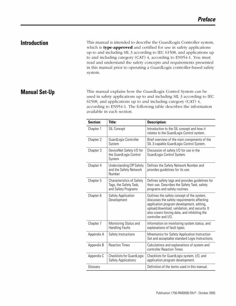
Manual Set-Up This manual explains how the GuardLogix Control System can be used in safety applications up to and including SIL 3 according to IEC 61508, and applications up to and including category (CAT) 4, according to EN954-1. The following table describes the information available in each section.
Section: Title: Description:
Chapter 1 SIL Concept Introduction to the SIL concept and how it relates to the GuardLogix Control system.
Chapter 2 GuardLogix Controller System
Brief overview of the main components of the SIL 3-capable GuardLogix Control System.
Chapter 3 DeviceNet Safety I/O for the GuardLogix Control System
Discussion of safety I/O for use in the GuardLogix Control System.
Chapter 4 Understanding CIP Safety and the Safety Network Number
Defines the Safety Network Number and provides guidelines for its use.
Chapter 5 Characteristics of Safety Tags, the Safety Task, and Safety Programs
Defines safety tags and provides guidelines for their use. Describes the Safety Task, safety programs and safety routines.
Chapter 6 Safety Application Development
Outlines the safety concept of the system, discusses the safety requirements affecting application program development, editing, upload/download, validation, and security. It also covers forcing data, and inhibiting the controller and I/O.
Chapter 7 Monitoring Status and Handling Faults
Information on monitoring system status, and explanations of fault types.
Appendix A Safety Instructions Mnemonics for Safety Application Instruction Set and acceptable standard Logix Instructions.
Appendix B Reaction Times Calculations and explanations of system and controller Reaction Times.
Appendix C Checklists for GuardLogix Safety Applications
Checklists for GuardLogix system, I/O, and application program development.
Glossary Definition of the terms used in this manual.
1 Publication 1756-RM093B-EN-P - October 2005
Preface 2
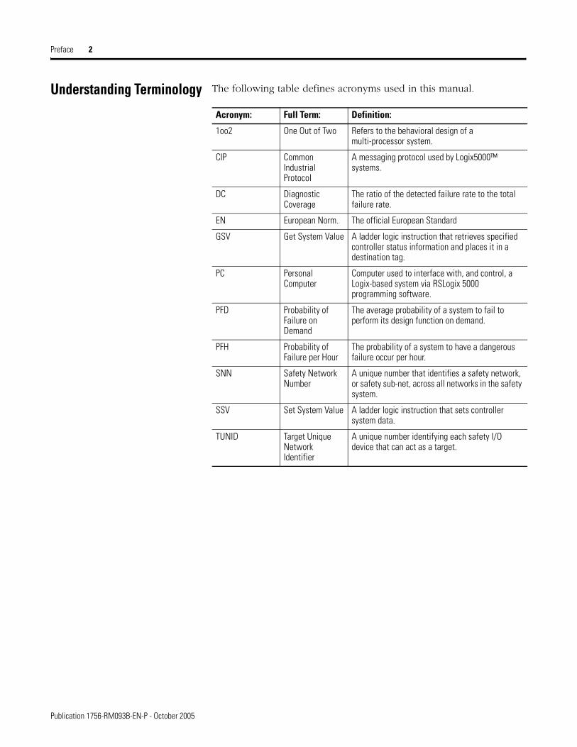
Understanding Terminology The following table defines acronyms used in this manual.
Acronym: Full Term: Definition:
1oo2 One Out of Two Refers to the behavioral design of a multi-processor system.
CIP Common Industrial Protocol
A messaging protocol used by Logix5000™ systems.
DC Diagnostic Coverage
The ratio of the detected failure rate to the total failure rate.
EN European Norm. The official European Standard
GSV Get System Value A ladder logic instruction that retrieves specified controller status information and places it in a destination tag.
PC Personal Computer
Computer used to interface with, and control, a Logix-based system via RSLogix 5000 programming software.
PFD Probability of Failure on Demand
The average probability of a system to fail to perform its design function on demand.
PFH Probability of Failure per Hour
The probability of a system to have a dangerous failure occur per hour.
SNN Safety Network Number
A unique number that identifies a safety network, or safety sub-net, across all networks in the safety system.
SSV Set System Value A ladder logic instruction that sets controller system data.
TUNID Target Unique Network Identifier
A unique number identifying each safety I/O device that can act as a target.
Publication 1756-RM093B-EN-P - October 2005
Preface 3
Related Documentation
The table below provides a listing of publications that contain important information about GuardLogix Controller systems.
If you would like a manual, you can:
• download a free electronic version from the internet atwww.rockwellautomation.com/literature.
• purchase a printed manual by contacting your local Allen-Bradley distributor or Rockwell Automation sales office.
For Read this document Document number
Information on installing the GuardLogix Controller GuardLogix Controller Installation Instructions 1756-IN045
Information on configuration and programming for the GuardLogix System
GuardLogix User Manual 1756-UM020
Information on the GuardLogix Safety Application Instruction Set
GuardLogix Safety Application Instruction Set Reference Manual
1756-RM095
Information on installing DeviceNet Safety I/O Modules DeviceNet Safety I/O Installation Instructions 1791DS-IN001
Information on using DeviceNet Safety I/O Modules DeviceNet Safety I/O User Manual 1791DS-UM001
Information on the Logix5000 Instruction Set Logix5000™ General Instruction Set Reference Manual 1756-RM003
Information on programming Logix5000 controllers Logix™ Common Procedures Programming Manual 1756-PM001
Information on using RSLogix 5000 Import/Export Utility Logix™ Import Export Reference Manual 1756-RM084
Publication 1756-RM093B-EN-P - October 2005

Preface 4
Publication 1756-RM093B-EN-P - October 2005
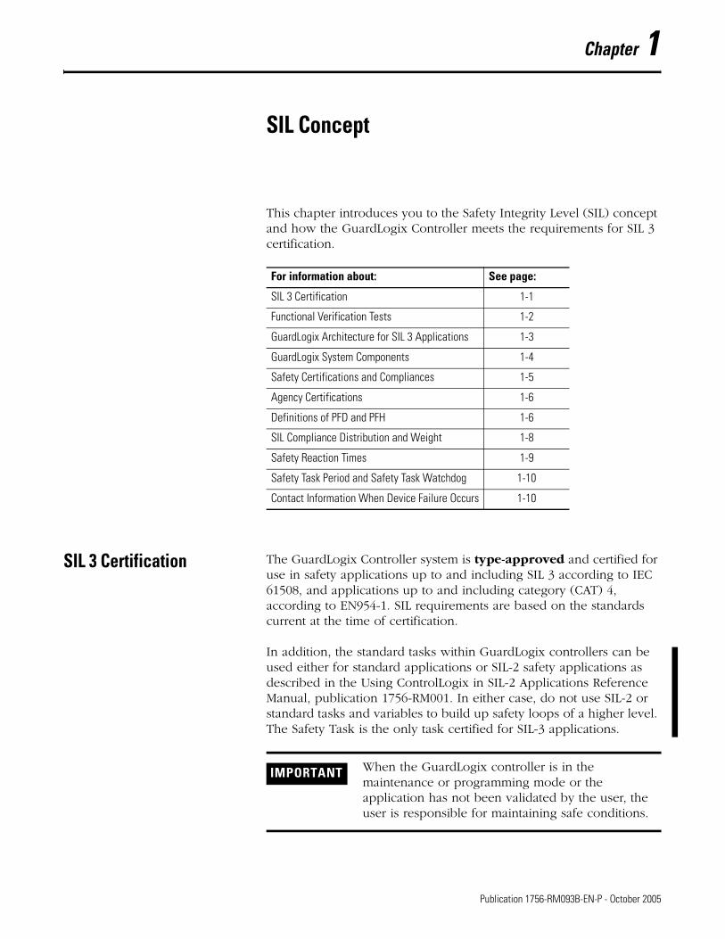
Chapter 1
SIL Concept
This chapter introduces you to the Safety Integrity Level (SIL) concept and how the GuardLogix Controller meets the requirements for SIL 3 certification.
SIL 3 Certification The GuardLogix Controller system is type-approved and certified for use in safety applications up to and including SIL 3 according to IEC 61508, and applications up to and including category (CAT) 4, according to EN954-1. SIL requirements are based on the standards current at the time of certification.
In addition, the standard tasks within GuardLogix controllers can be used either for standard applications or SIL-2 safety applications as described in the Using ControlLogix in SIL-2 Applications Reference Manual, publication 1756-RM001. In either case, do not use SIL-2 or standard tasks and variables to build up safety loops of a higher level. The Safety Task is the only task certified for SIL-3 applications.
For information about: See page:
SIL 3 Certification 1-1
Functional Verification Tests 1-2
GuardLogix Architecture for SIL 3 Applications 1-3
GuardLogix System Components 1-4
Safety Certifications and Compliances 1-5
Agency Certifications 1-6
Definitions of PFD and PFH 1-6
SIL Compliance Distribution and Weight 1-8
Safety Reaction Times 1-9
Safety Task Period and Safety Task Watchdog 1-10
Contact Information When Device Failure Occurs 1-10
IMPORTANT When the GuardLogix controller is in the maintenance or programming mode or the application has not been validated by the user, the user is responsible for maintaining safe conditions.
1 Publication 1756-RM093B-EN-P - October 2005
1-2 SIL Concept
RSLogix 5000 programming software is required to create programs for the GuardLogix controller.
The TÜV Rheinland has approved the GuardLogix Controller system for use in safety-related applications up to SIL 3, in which the de-energized state is considered to be the safe state. All of the examples related to I/O included in this manual are based on achieving de-energization as the safe state for typical Machine Safety and Emergency Shutdown (ESD) Systems.
When applying Functional Safety, restrict access to qualified, authorized personnel who are trained and experienced. The Safety-Lock function, with passwords, is provided in RSLogix 5000. For information on using the Safety-Lock feature, refer to the GuardLogix Controllers User Manual, publication number 1756-UM020.
Functional Verification Tests
IEC 61508 requires the user to perform various functional verification tests of the equipment used in the system. Functional verification tests are performed at user-defined times. For example, functional verification test intervals can be once a year, once every fifteen years or whatever timeframe is appropriate.
The GuardLogix controller has a functional verification test interval of 15 years. Other components of the system, such as Safety I/O modules, sensors, and actuators generally have shorter functional verification test intervals. The controller should be included in the functional verification testing of the other components in the safety system.
IMPORTANT The system user is responsible for:
• the set-up, SIL rating, and validation of any sensors or actuators connected to the GuardLogix system.
• project management and functional testing.
• access control to the safety system, including password handling.
• programming the application software and the device configurations in accordance with the information in this safety reference manual and the GuardLogix Controllers User Manual, publication number 1756-UM020.
IMPORTANT Users’ specific applications determine the timeframe for the functional verification test interval. However this is mainly related to Safety I/O modules and field instrumentation.
Publication 1756-RM093B-EN-P - October 2005
SIL Concept 1-3
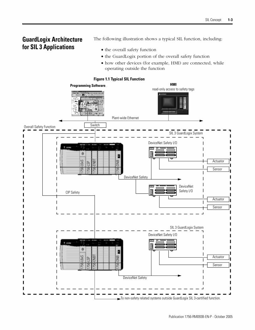
GuardLogix Architecture for SIL 3 Applications
The following illustration shows a typical SIL function, including:
• the overall safety function
• the GuardLogix portion of the overall safety function
• how other devices (for example, HMI) are connected, while operating outside the function
Figure 1.1 Typical SIL Function
1756
-DN
BPlant-wide Ethernet
SIL 3 GuardLogix System
Programming Software. HMIread-only access to safety tags
To non-safety related systems outside GuardLogix SIL 3-certified function.
Overall Safety Function
1756
-L6x
S
1756
-LSP
1756
-ENB
T
1756
-DN
B
1756
-L6x
S
1756
-LSP
1756
-EN
BT
Switch
DeviceNet Safety
Actuator
DeviceNet Safety
Sensor
DeviceNet Safety I/O
DeviceNet Safety I/O
DeviceNet Safety I/O
CIP Safety
Actuator
Sensor
Actuator
Sensor
SIL 3 GuardLogix System
Publication 1756-RM093B-EN-P - October 2005
1-4 SIL Concept
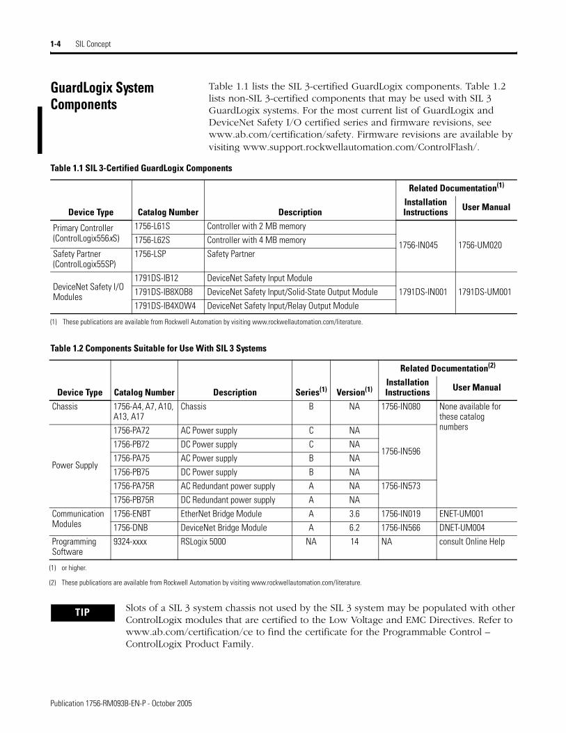
GuardLogix System Components
Table 1.1 lists the SIL 3-certified GuardLogix components. Table 1.2 lists non-SIL 3-certified components that may be used with SIL 3 GuardLogix systems. For the most current list of GuardLogix and DeviceNet Safety I/O certified series and firmware revisions, see www.ab.com/certification/safety. Firmware revisions are available by visiting www.support.rockwellautomation.com/ControlFlash/.
Table 1.1 SIL 3-Certified GuardLogix Components
Device Type Catalog Number Description
Related Documentation(1)
Installation Instructions User Manual
Primary Controller(ControlLogix556xS)
1756-L61S Controller with 2 MB memory
1756-IN045 1756-UM0201756-L62S Controller with 4 MB memory
Safety Partner(ControlLogix55SP)
1756-LSP Safety Partner
DeviceNet Safety I/O Modules
1791DS-IB12 DeviceNet Safety Input Module
1791DS-IN001 1791DS-UM0011791DS-IB8XOB8 DeviceNet Safety Input/Solid-State Output Module
1791DS-IB4XOW4 DeviceNet Safety Input/Relay Output Module
(1) These publications are available from Rockwell Automation by visiting www.rockwellautomation.com/literature.
Table 1.2 Components Suitable for Use With SIL 3 Systems
Device Type Catalog Number Description
Related Documentation(2)
Series(1) Version(1)Installation Instructions User Manual
Chassis 1756-A4, A7, A10, A13, A17
Chassis B NA 1756-IN080 None available for these catalog numbers
Power Supply
1756-PA72 AC Power supply C NA
1756-IN5961756-PB72 DC Power supply C NA
1756-PA75 AC Power supply B NA
1756-PB75 DC Power supply B NA
1756-PA75R AC Redundant power supply A NA 1756-IN573
1756-PB75R DC Redundant power supply A NA
Communication Modules
1756-ENBT EtherNet Bridge Module A 3.6 1756-IN019 ENET-UM001
1756-DNB DeviceNet Bridge Module A 6.2 1756-IN566 DNET-UM004
Programming Software
9324-xxxx RSLogix 5000 NA 14 NA consult Online Help
(1) or higher.
(2) These publications are available from Rockwell Automation by visiting www.rockwellautomation.com/literature.
TIP Slots of a SIL 3 system chassis not used by the SIL 3 system may be populated with other ControlLogix modules that are certified to the Low Voltage and EMC Directives. Refer to www.ab.com/certification/ce to find the certificate for the Programmable Control – ControlLogix Product Family.
Publication 1756-RM093B-EN-P - October 2005
SIL Concept 1-5
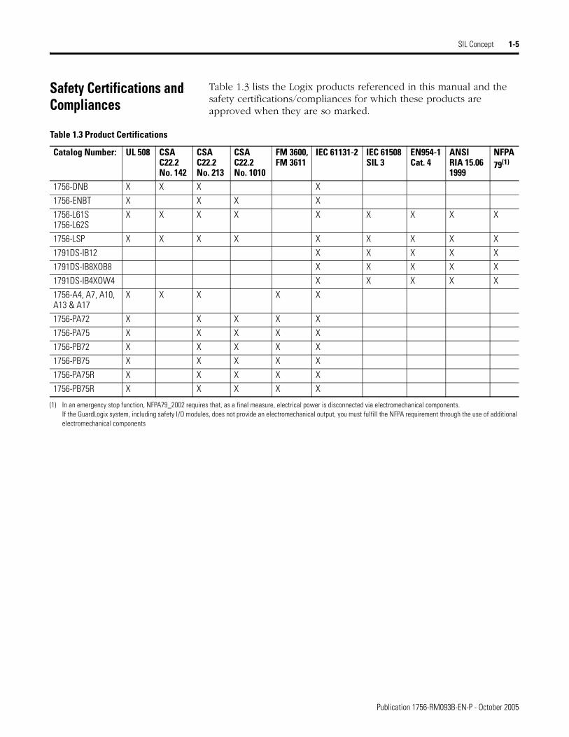
Safety Certifications and Compliances
Table 1.3 lists the Logix products referenced in this manual and the safety certifications/compliances for which these products are approved when they are so marked.
Table 1.3 Product Certifications
Catalog Number: UL 508 CSAC22.2No. 142
CSAC22.2No. 213
CSAC22.2No. 1010
FM 3600,FM 3611
IEC 61131-2 IEC 61508SIL 3
EN954-1Cat. 4
ANSIRIA 15.061999
NFPA 79(1)
1756-DNB X X X X
1756-ENBT X X X X
1756-L61S1756-L62S
X X X X X X X X X
1756-LSP X X X X X X X X X
1791DS-IB12 X X X X X
1791DS-IB8XOB8 X X X X X
1791DS-IB4XOW4 X X X X X
1756-A4, A7, A10, A13 & A17
X X X X X
1756-PA72 X X X X X
1756-PA75 X X X X X
1756-PB72 X X X X X
1756-PB75 X X X X X
1756-PA75R X X X X X
1756-PB75R X X X X X
(1) In an emergency stop function, NFPA79_2002 requires that, as a final measure, electrical power is disconnected via electromechanical components.If the GuardLogix system, including safety I/O modules, does not provide an electromechanical output, you must fulfill the NFPA requirement through the use of additional electromechanical components
Publication 1756-RM093B-EN-P - October 2005
1-6 SIL Concept
Agency Certifications GuardLogix user documentation typically lists the agency certifications for which the products are approved. If a product has achieved agency certification, it is marked as such on the product labeling. Product certifications are listed in the product’s specifications table, as shown in the example below.
GuardLogix PFD and PFH Specifications
Definitions of PFD and PFH
Safety-related systems can be classified as operating in either a low demand mode, or in a high demand/continuous mode. IEC 61508 quantifies this classification by stating that the frequency of demands for operation of the safety system is no greater than once per year in the low demand mode, or greater than once per year in high demand/continuous mode.
The SIL value for a low demand safety-related system is directly related to order-of-magnitude ranges of its average probability of failure to satisfactorily perform its safety function on demand or, simply, probability of failure on demand (PFD). The SIL value for a high demand/continuous mode safety-related system is directly related to the probability of a dangerous failure occurring per hour (PFH).
Although PFD and PFH values are usually associated with each of the three elements making up a safety-related system (the sensors, the actuators, and the logic element), they can be associated with each component of the logic element, that is, each module of a programmable controller.
Certification UL UL Listed Industrial Control Equipment
CSA CSA Certified Process Control Equipment for Class I, Division 2 Group A,B,C,D Hazardous Locations
FM FM Approved Equipment for use in Class I Division 2 Group A,B,C,D Hazardous Locations
CE European Union 89/336/EEC EMC and Low Voltage Directives, compliant with:EN61000-6-4; Industrial Emissions
C-Tick Australian Radio Communications Act, compliant with:AS/NZS 2064; Industrial Emissions
TÜV Functional Safety: SIL 1 to 3, according to IEC 61508; Category 1 to 4, according to EN954-1.
Publication 1756-RM093B-EN-P - October 2005

SIL Concept 1-7
PFD and PFH Calculations
The PFD and PFH calculations in the tables below are based on the equations from Part 6 of IEC 61508 with the following assumptions:
• The architecture is 1oo2.
• A detected error in either channel will result in the outputs being transitioned to their safe state.
• The functional verification test interval (T1) is 15 years (131,400 hours).
• The hardware fault tolerance equals 1.
• The safe failure fraction is 99.1%.
• The fraction of detected common cause failures (βD) is 0.5%.
• The fraction of undetected common cause failures (β) is 1.0%
Table 1.4 PFD Values for GuardLogix Controller System Components
Component Functional Verification Test Interval
PFD
1756-L6xS and 1756-LSP 15 years 8.5E-6
1791DS-IB12
3 months 9.58E-7
6 months 1.92E-6
1 year 3.83E-6
2 years 7.66E-6
1791DS-IB8XOB8
3 months 1.21E-6
6 months 2.41E-6
1 year 4.82E-6
2 years 9.64E-6
1791DS-IB4XOW43 months 5.81E-6
6 months 1.18 E-5
Table 1.5 PFH Values for GuardLogix Controller System Components
Component Functional Verification Test Interval
PFH
1756-L6xS and 1756-LSP 15 years 1.9E-10
1791DS-IB12 3 months 8.75E-10
1791DS-IB8XOB8 3 months 1.11E-9
1791DS-IB4XOW4 3 months 5.24E-9
Publication 1756-RM093B-EN-P - October 2005
1-8 SIL Concept
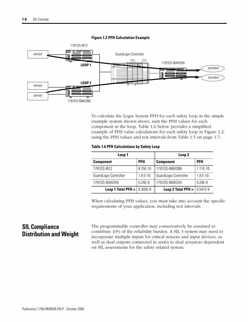
Figure 1.2 PFH Calculation Example
To calculate the Logix System PFH for each safety loop in the simple example system shown above, sum the PFH values for each component in the loop. Table 1.6 below provides a simplified example of PFH value calculations for each safety loop in Figure 1.2, using the PFH values and test intervals from Table 1.5 on page 1-7.
When calculating PFH values, you must take into account the specific requirements of your application, including test intervals.
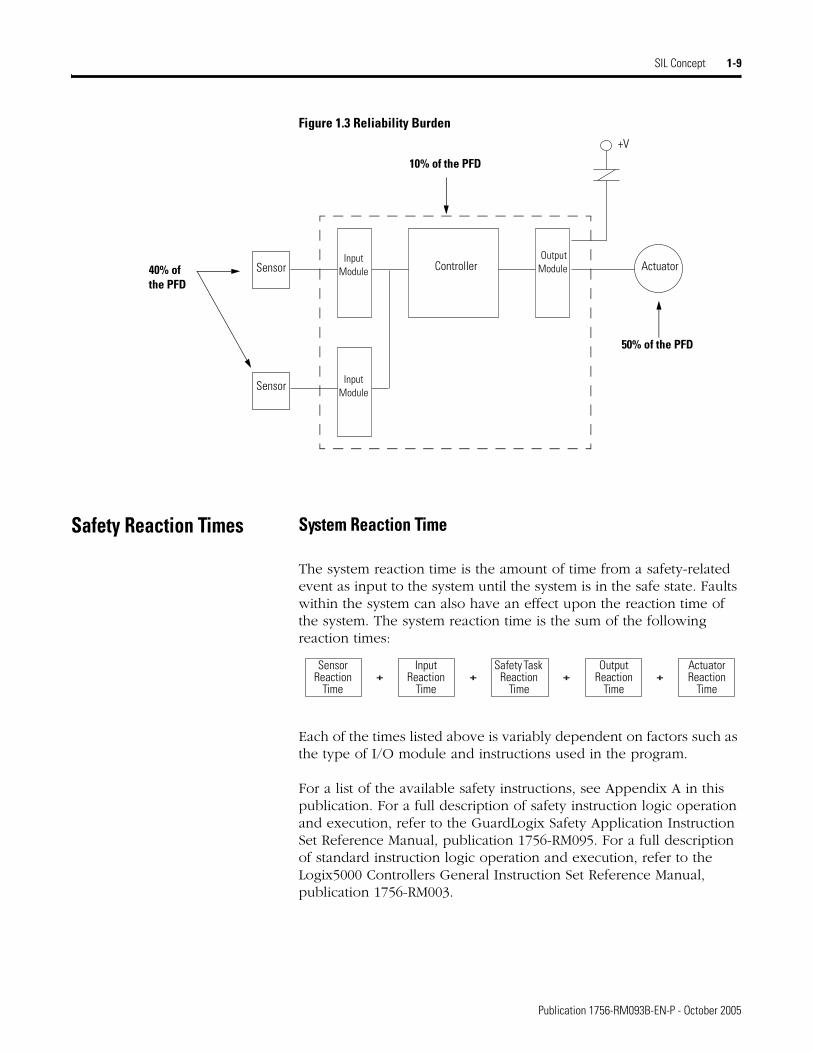
SIL Compliance Distribution and Weight
The programmable controller may conservatively be assumed to contribute 10% of the reliability burden. A SIL 3 system may need to incorporate multiple inputs for critical sensors and input devices, as well as dual outputs connected in series to dual actuators dependent on SIL assessments for the safety related system.
DeviceNet EtherNetLogix5562S Logix55LSP
sensor
sensor
sensor
1791DS-IB12
GuardLogix Controller
1791DS-IB8XOB8
1791DS-IB4XOX4actuator
actuator
LOOP 1
LOOP 2
Table 1.6 PFH Calculations by Safety Loop
Loop 1 Loop 2
Component PFH Component PFH
1791DS-IB12 8.75E-10 1791DS-IB8XOB8 1.11E-10
GuardLogix Controller 1.9 E-10 GuardLogix Controller 1.9 E-10
1791DS-IB4XOX4 5.24E-9 1791DS-IB4XOX4 5.24E-9
Loop 1 Total PFH = 6.305E-9 Loop 2 Total PFH = 5.541E-9
Publication 1756-RM093B-EN-P - October 2005
SIL Concept 1-9
Figure 1.3 Reliability Burden
Safety Reaction Times System Reaction Time
The system reaction time is the amount of time from a safety-related event as input to the system until the system is in the safe state. Faults within the system can also have an effect upon the reaction time of the system. The system reaction time is the sum of the following reaction times:
Each of the times listed above is variably dependent on factors such as the type of I/O module and instructions used in the program.
For a list of the available safety instructions, see Appendix A in this publication. For a full description of safety instruction logic operation and execution, refer to the GuardLogix Safety Application Instruction Set Reference Manual, publication 1756-RM095. For a full description of standard instruction logic operation and execution, refer to the Logix5000 Controllers General Instruction Set Reference Manual, publication 1756-RM003.
ActuatorController Output Module
+V
Input Module
Sensor
Sensor
40% of the PFD
10% of the PFD
50% of the PFD
Input Module
+ + + +Sensor
Reaction Time
Input Reaction
Time
Safety Task Reaction
Time
Output Reaction
Time
Actuator Reaction
Time
Publication 1756-RM093B-EN-P - October 2005
1-10 SIL Concept
Safety Task Reaction Time
The Safety Task Reaction Time is the worst-case delay from any input change presented to the controller until the processed output is set by the output producer. It is less than or equal to the sum of the Safety Task Period and the Safety Task Watchdog.
Safety Task Period and Safety Task Watchdog
The Safety Task Period is the period at which the Safety Task executes.
The Safety Task Watchdog time is the maximum permissible time for Safety Task processing. If the cycle time exceeds the Safety Task Watchdog time, a non-recoverable safety fault occurs in the controller and outputs transition to the safe state (off) automatically. For more information on faults, see Chapter 7, ‘Monitoring Status and Handling Faults’.
The Safety Task Watchdog time is user-defined, but must be less than or equal to the Safety Task Period.
The Safety Task Watchdog time is set in the task properties window of RSLogix 5000 software. This value can be modified online, regardless of controller mode, but it cannot be changed once the controller is Safety-Locked or once a Safety Signature is created. See Chapter 6 for more information on Safety-Lock and the Safety Signature.
For information on calculating the safety system reaction times, see Appendix B, Reaction Times.
Contact Information When Device Failure Occurs
If you experience a failure with any SIL 3-certified device, contact your local Rockwell Automation distributor. With this contact, you can:
• return the device to Rockwell Automation so the failure is appropriately logged for the catalog number affected and a record is made of the failure.
• request a failure analysis (if necessary) to try to determine the cause of the failure.
Publication 1756-RM093B-EN-P - October 2005
Chapter 2
GuardLogix Controller System
This chapter discusses the GuardLogix Control System components, including the primary controller and safety partner, chassis, power supply, communication bridges, and the programming software.
For a brief listing of components suitable for use in SIL 3 applications, see Table 1.2 on page 1-4. For more detailed and up-to-date information see www.ab.com/certification/safety.
When installing a GuardLogix controller, follow the information in the GuardLogix Controllers Installation Instructions, publication 1756-IN045.
GuardLogix Controller Hardware
The GuardLogix controller consists of a Primary Controller, catalog number 1756-L61S or 1756-L62S, and a Safety Partner, catalog number 1756-LSP. These two modules work in a 1oo2 architecture to create the SIL 3-capable controller. They are described in the following sections.
Both the Primary Controller and Safety Partner perform power-up and run-time functional diagnostic tests of all safety-related components in the controller.
Both also feature status LEDs. For details on LED operation, refer to the GuardLogix Controllers User Manual, publication 1756-UM020.
Primary Controller
The Primary Controller is the processor that performs standard and safety functions and communicates with the Safety Partner for safety-related functions in the GuardLogix Control System. The Primary Controller consists of a central processor, I/O interface and memory.
IMPORTANT LEDs are not reliable indicators for safety functions. They should be used only for general diagnostics during commissioning or troubleshooting. Do not attempt to use LEDs as operational indicators.
1 Publication 1756-RM093B-EN-P - October 2005
2-2 GuardLogix Controller System
Safety Partner
In order to satisfy SIL 3 requirements, a Safety Partner, catalog number 1756-LSP, must be installed in the slot immediately to the right of the Primary Controller. The Safety Partner is a co-processor that provides redundancy for safety-related functions in the system.
The Safety Partner is configured by the Primary Controller. Only a single download of the user program to the primary controller is required. The Safety Partner’s operating mode is controlled by the Primary Controller.
Safety I/O For information on DeviceNet Safety I/O modules for use with the GuardLogix controller, see Chapter 3.
Chassis The 1756-Axx chassis provides the physical connections between modules and the GuardLogix system. Any failure, though unlikely, would be detected as a failure by one or more of the active components of the system. Therefore, the chassis is not relevant to the safety discussion.
Power Supplies ControlLogix power supplies suitable for use in SIL 3 applications include:
• 1756-PA72 AC power supply
• 1756-PA75 AC power supply
• 1756-PB72 DC power supply
• 1756-PB75 DC power supply
• 1756-PA75R AC power supply (redundant)
• 1756-PB75R DC power supply (redundant)
• 1756-PSCA or 1756-PSCA2 Redundant power supply chassis adapter (required for use with redundant power supplies)
No extra configuration or wiring is required for SIL 3 operation of the ControlLogix power supplies. Any failure, though unlikely, would be detected as a failure by one or more of the active components of the GuardLogix system. Therefore, the power supply is not relevant to the safety discussion.
Publication 1756-RM093B-EN-P - October 2005
GuardLogix Controller System 2-3
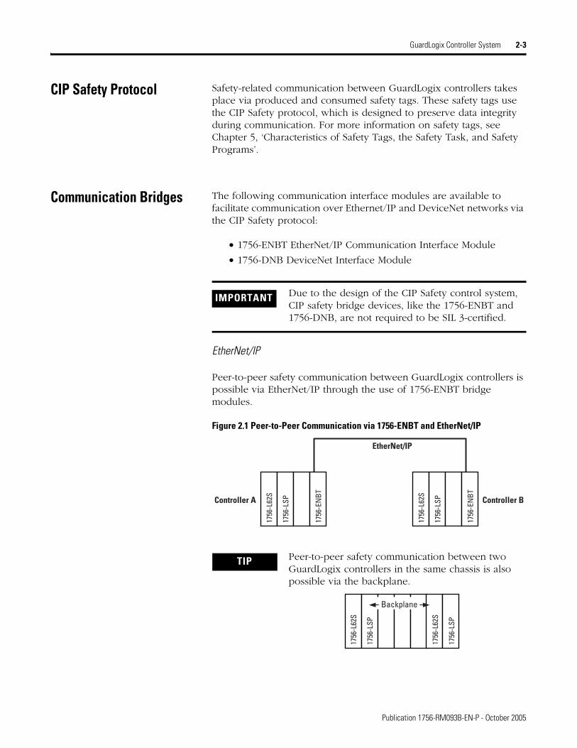
CIP Safety Protocol Safety-related communication between GuardLogix controllers takes place via produced and consumed safety tags. These safety tags use the CIP Safety protocol, which is designed to preserve data integrity during communication. For more information on safety tags, see Chapter 5, ‘Characteristics of Safety Tags, the Safety Task, and Safety Programs’.
Communication Bridges The following communication interface modules are available to facilitate communication over Ethernet/IP and DeviceNet networks via the CIP Safety protocol:
• 1756-ENBT EtherNet/IP Communication Interface Module
• 1756-DNB DeviceNet Interface Module
EtherNet/IP
Peer-to-peer safety communication between GuardLogix controllers is possible via EtherNet/IP through the use of 1756-ENBT bridge modules.
Figure 2.1 Peer-to-Peer Communication via 1756-ENBT and EtherNet/IP
IMPORTANT Due to the design of the CIP Safety control system, CIP safety bridge devices, like the 1756-ENBT and 1756-DNB, are not required to be SIL 3-certified.
TIP Peer-to-peer safety communication between two GuardLogix controllers in the same chassis is also possible via the backplane.
Controller A Controller B
1756
-L62
S
1756
-LSP
1756
-EN
BT
1756
-L62
S
1756
-LSP
1756
-EN
BT
EtherNet/IP
1756
-L62
S
1756
-LSP
1756
-L62
S
1756
-LSP
Backplane
Publication 1756-RM093B-EN-P - October 2005
2-4 GuardLogix Controller System
DeviceNet Safety
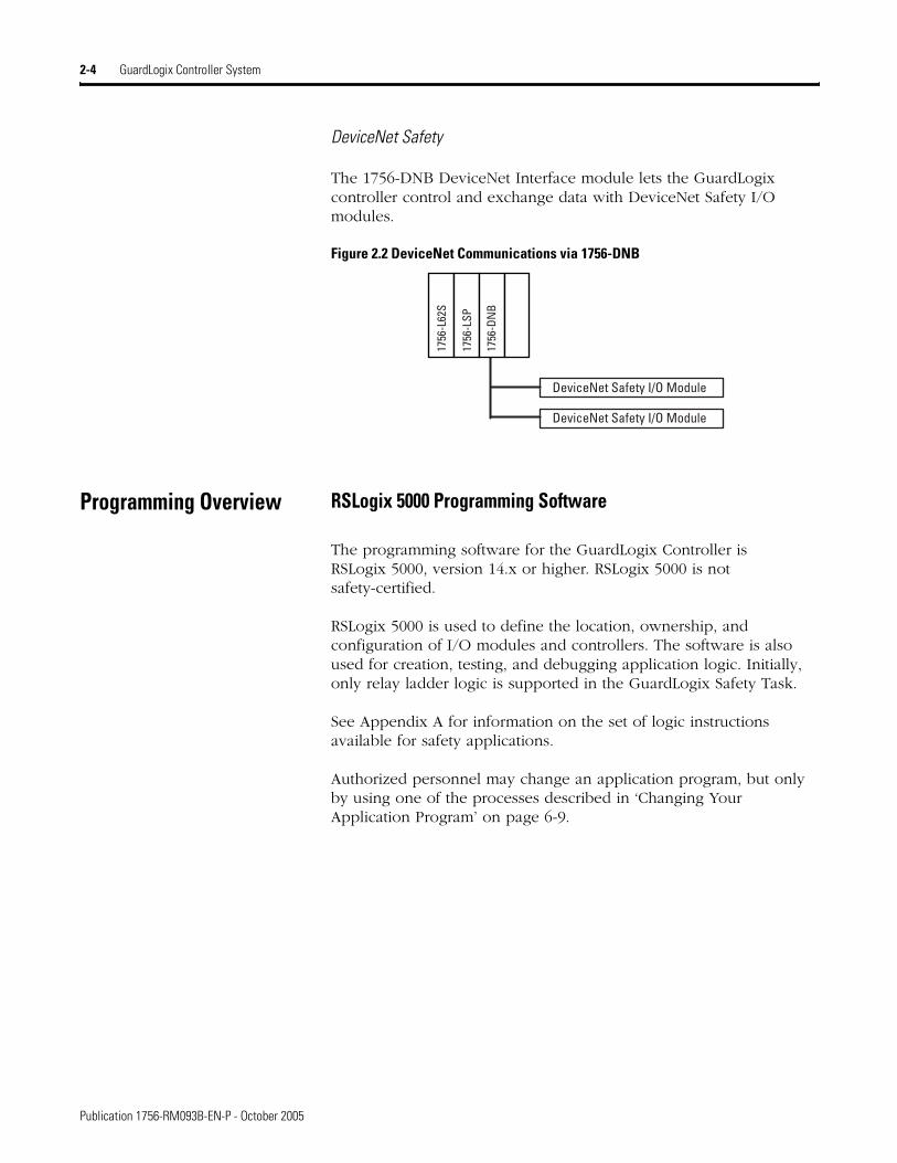
The 1756-DNB DeviceNet Interface module lets the GuardLogix controller control and exchange data with DeviceNet Safety I/O modules.
Figure 2.2 DeviceNet Communications via 1756-DNB
Programming Overview RSLogix 5000 Programming Software
The programming software for the GuardLogix Controller is RSLogix 5000, version 14.x or higher. RSLogix 5000 is not safety-certified.
RSLogix 5000 is used to define the location, ownership, and configuration of I/O modules and controllers. The software is also used for creation, testing, and debugging application logic. Initially, only relay ladder logic is supported in the GuardLogix Safety Task.
See Appendix A for information on the set of logic instructions available for safety applications.
Authorized personnel may change an application program, but only by using one of the processes described in ‘Changing Your Application Program’ on page 6-9.
DeviceNet Safety I/O Module
DeviceNet Safety I/O Module
1756
-L62
S
1756
-LSP
1756
-DN
B
Publication 1756-RM093B-EN-P - October 2005
Chapter 3
DeviceNet Safety I/O for the GuardLogix Control System
Overview Before operating a GuardLogix safety system containing DeviceNet Safety I/O, you must read, understand, and follow the installation, operation, and safety information provided in the publications listed in Table 1.1 on page 1-4.
Field DeviceNet Safety I/O can be connected to safety input and output devices, allowing these devices to be controlled by the GuardLogix control system. For safety data, I/O communications are performed through safety connections using the DeviceNet Safety Protocol; logic is processed in the safety controller.
Typical Safety Functions of DeviceNet Safety I/O Modules
Safe State
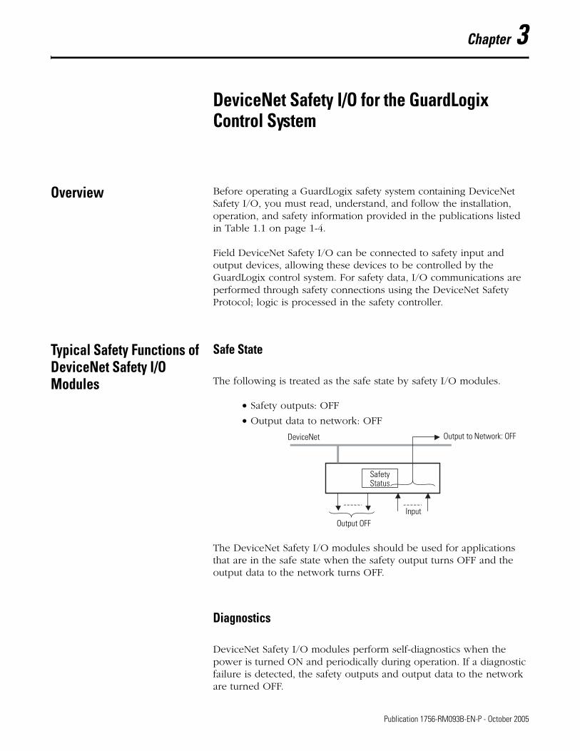
The following is treated as the safe state by safety I/O modules.
• Safety outputs: OFF
• Output data to network: OFF
The DeviceNet Safety I/O modules should be used for applications that are in the safe state when the safety output turns OFF and the output data to the network turns OFF.
Diagnostics
DeviceNet Safety I/O modules perform self-diagnostics when the power is turned ON and periodically during operation. If a diagnostic failure is detected, the safety outputs and output data to the network are turned OFF.
DeviceNet Output to Network: OFF
Safety Status
Output OFFInput
1 Publication 1756-RM093B-EN-P - October 2005
3-2 DeviceNet Safety I/O for the GuardLogix Control System
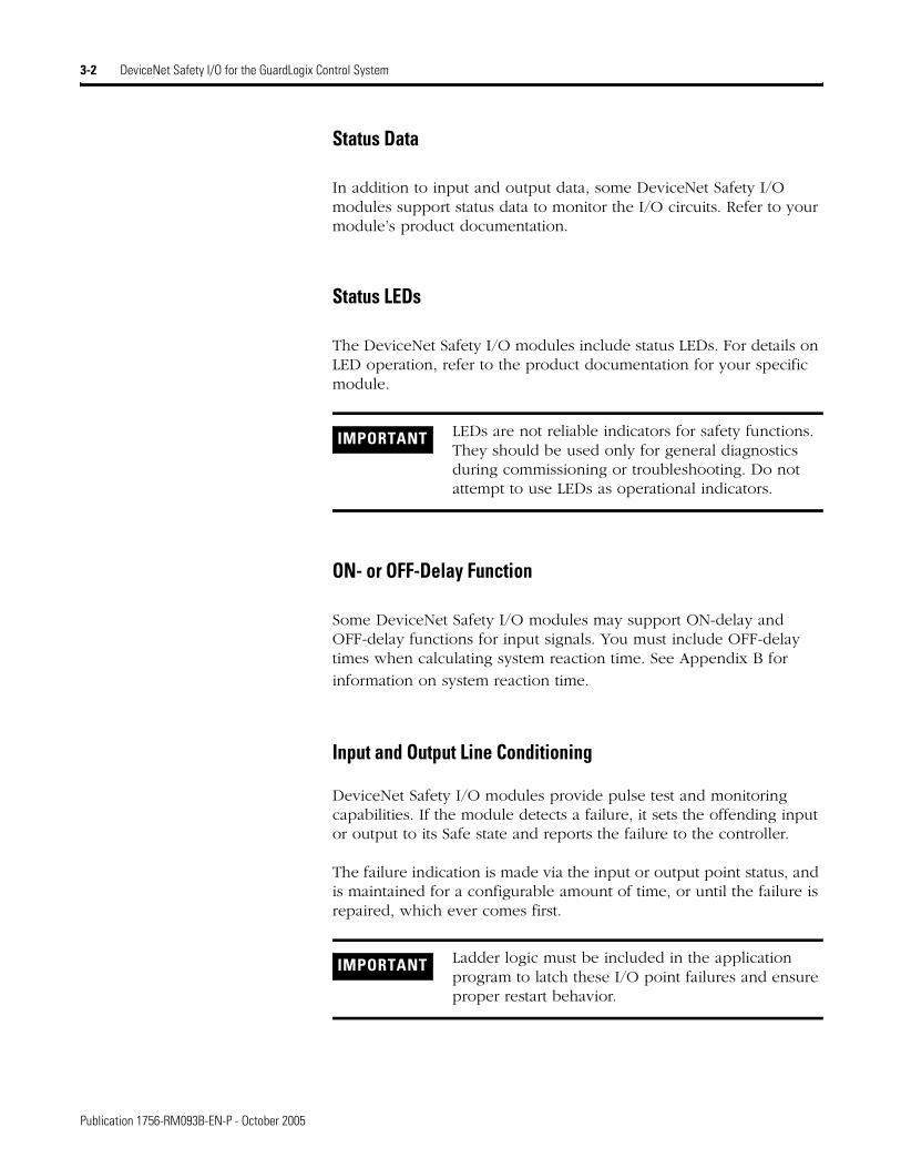
Status Data
In addition to input and output data, some DeviceNet Safety I/O modules support status data to monitor the I/O circuits. Refer to your module’s product documentation.
Status LEDs
The DeviceNet Safety I/O modules include status LEDs. For details on LED operation, refer to the product documentation for your specific module.
ON- or OFF-Delay Function
Some DeviceNet Safety I/O modules may support ON-delay and OFF-delay functions for input signals. You must include OFF-delay times when calculating system reaction time. See Appendix B for
information on system reaction time.
Input and Output Line Conditioning
DeviceNet Safety I/O modules provide pulse test and monitoring capabilities. If the module detects a failure, it sets the offending input or output to its Safe state and reports the failure to the controller.
The failure indication is made via the input or output point status, and is maintained for a configurable amount of time, or until the failure is repaired, which ever comes first.
IMPORTANT LEDs are not reliable indicators for safety functions. They should be used only for general diagnostics during commissioning or troubleshooting. Do not attempt to use LEDs as operational indicators.
IMPORTANT Ladder logic must be included in the application program to latch these I/O point failures and ensure proper restart behavior.
Publication 1756-RM093B-EN-P - October 2005
DeviceNet Safety I/O for the GuardLogix Control System 3-3
I/O Module Connection Status
A CIP Safety system provides connnection status for each I/O device in the safety system. If an input connection failure is detected, the operating system sets all associated inputs to their de-energized (Safe) state, and reports the failure to the ladder logic. If an output connection failure is detected, the operating system can only report the failure to the ladder logic; the outputs are de-energized by the output module.
How to Latch and Reset Faulted I/O
The diagrams in Figure 3.1 and Figure 3.2 provide examples of the ladder logic required to latch and reset an I/O module connection or point failure. Figure 3.1 shows the ladder logic required for an input point, Figure 3.2 shows the ladder logic required for an output point.
IMPORTANT Ladder logic must be included in the application program to monitor and latch any connection failures and ensure proper restart behavior.
IMPORTANT Both of these diagrams are examples, and are for illustrative purposes only. The suitability of this logic depends upon your specific system requirements.
Publication 1756-RM093B-EN-P - October 2005
3-4 DeviceNet Safety I/O for the GuardLogix Control System
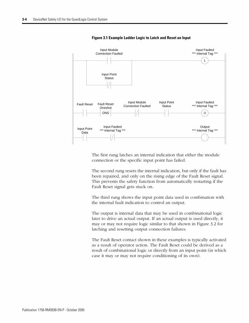
Figure 3.1 Example Ladder Logic to Latch and Reset an Input
The first rung latches an internal indication that either the module connection or the specific input point has failed.
The second rung resets the internal indication, but only if the fault has been repaired, and only on the rising edge of the Fault Reset signal. This prevents the safety function from automatically restarting if the Fault Reset signal gets stuck on.
The third rung shows the input point data used in combination with the internal fault indication to control an output.
The output is internal data that may be used in combinational logic later to drive an actual output. If an actual output is used directly, it may or may not require logic similar to that shown in Figure 3.2 for latching and resetting output connection failures.
The Fault Reset contact shown in these examples is typically activated as a result of operator action. The Fault Reset could be derived as a result of combinational logic or directly from an input point (in which case it may or may not require conditioning of its own).
L
Input ModuleConnection Faulted
Input Faulted*** Internal Tag ***
Input PointStatus
Fault Reset
ONS
Fault ResetOneshot
U
Input Faulted*** Internal Tag ***
Input PointData
Input Faulted*** Internal Tag ***
Output*** Internal Tag ***
Input ModuleConnection Faulted
Input PointStatus
Publication 1756-RM093B-EN-P - October 2005
DeviceNet Safety I/O for the GuardLogix Control System 3-5
Figure 3.2 Example Ladder Logic to Latch and Reset an Output
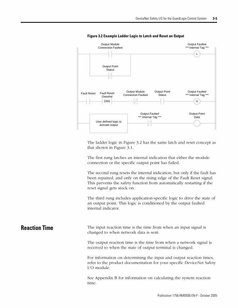
The ladder logic in Figure 3.2 has the same latch and reset concept as that shown in Figure 3.1.
The first rung latches an internal indication that either the module connection or the specific output point has failed.
The second rung resets the internal indication, but only if the fault has been repaired, and only on the rising edge of the Fault Reset signal. This prevents the safety function from automatically restarting if the reset signal gets stuck on.
The third rung includes application-specific logic to drive the state of an output point. This logic is conditioned by the output faulted internal indicator.
Reaction Time The input reaction time is the time from when an input signal is changed to when network data is sent.
The output reaction time is the time from when a network signal is received to when the state of output terminal is changed.
For information on determining the input and output reaction times, refer to the product documentation for your specific DeviceNet Safety I/O module.
See Appendix B for information on calculating the system reaction time.
L
Output ModuleConnection Faulted
Output Faulted*** Internal Tag ***
Output PointStatus
Fault Reset
ONS
Fault ResetOneshot
U
Output Faulted*** Internal Tag ***
Output Faulted*** Internal Tag ***
Output PointData
Output ModuleConnection Faulted
Output PointStatus
User defined logic toactivate output
Publication 1756-RM093B-EN-P - October 2005
3-6 DeviceNet Safety I/O for the GuardLogix Control System
Safety Considerations for I/O Modules on the Safety Network
You must commission all devices with the MAC ID and baud rate, if necessary, before their installation on the safety network.
Ownership
Every module in the GuardLogix system is ‘owned’ by only one controller in the architecture. When a controller owns an I/O module, it stores the module’s configuration data, as defined by the user. This data controls how the module behaves in the system.
A module can only be configured by one originator, which automatically becomes the configuration owner for that module. No other device can send configuration data to the module.
Configuration Signature
The Configuration Signature defines the module’s configuration and lets a non-owner device establish a connection. It can be read and monitored. The Configuration signature is used to uniquely identify a module’s configuration in several operations:
• During download from a configuration tool, the Configuration Signature provides you with a means to check that the device and the configuration tool agree on the information downloaded.
• During device replacement, the Configuration Signature allows you to verify that the configuration in the configuration tool is the correct configuration. If the originator is used to automatically configure a device, the Configuration Signature indicates whether reconfiguration is necessary and ensures the integrity of the operation.
• During connection establishment, the originator and the target devices use the Configuration Signature to ensure that both devices are using the same configuration data.
TIP Ownership applies to outputs. An output or output assembly can only have one owner.
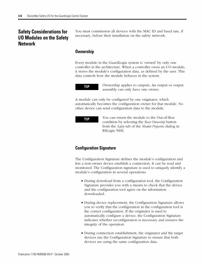
TIP You can return the module to the Out-of-Box condition by selecting the Reset Ownership button from the Safety tab of the Module Properties dialog in RSLogix 5000.
Publication 1756-RM093B-EN-P - October 2005
DeviceNet Safety I/O for the GuardLogix Control System 3-7
The Configuration Signature is auto-generated by RSLogix 5000 when an I/O module is added to the GuardLogix controller project.
I/O Module Replacement
The replacement of safety devices requires that the replacement device be configured properly and that the replacement device’s operation be user-verified.
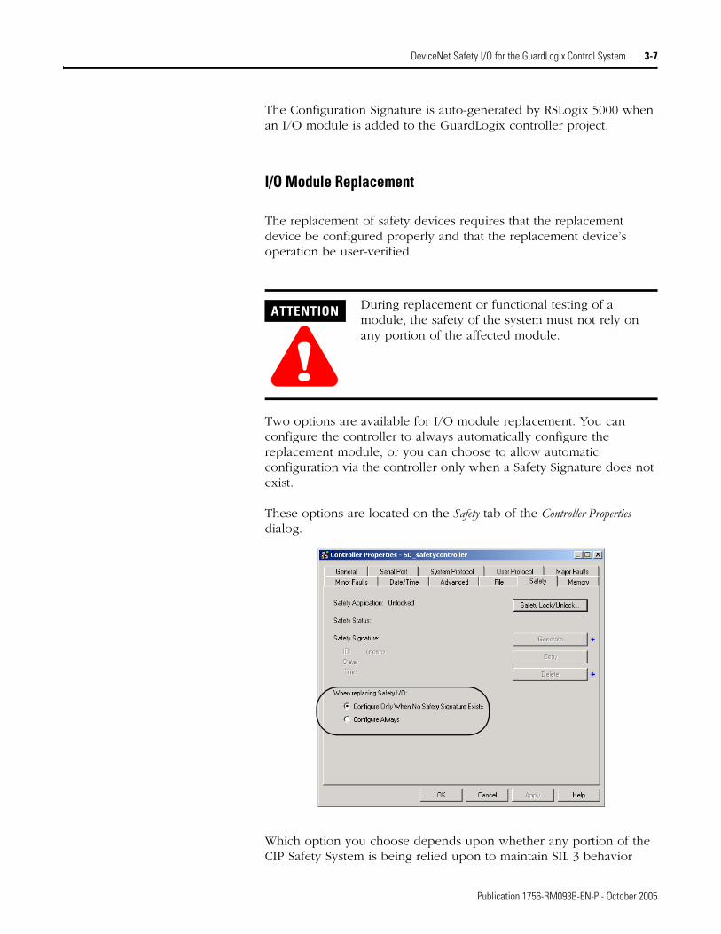
Two options are available for I/O module replacement. You can configure the controller to always automatically configure the replacement module, or you can choose to allow automatic configuration via the controller only when a Safety Signature does not exist.
These options are located on the Safety tab of the Controller Properties dialog.
Which option you choose depends upon whether any portion of the CIP Safety System is being relied upon to maintain SIL 3 behavior
ATTENTION
!During replacement or functional testing of a module, the safety of the system must not rely on any portion of the affected module.
Publication 1756-RM093B-EN-P - October 2005
3-8 DeviceNet Safety I/O for the GuardLogix Control System
during the replacement and functional testing of the module, as described below.
Refer to the GuardLogix Controller User Manual, publication number 1756-UM020, for more information on replacing an I/O module.
ATTENTION
!Enable the Configure Always feature only if the entire routable CIP Safety Control System is not being relied on to maintain SIL 3 behavior during the replacement and functional testing of a module.
If other parts of the CIP Safety Control System are being relied upon to maintain SIL 3, ensure that the controller’s Configure Always feature is disabled.
Do not place any modules in the Out-of-Box condition on any CIP Safety Network when the Configure Always feature is enabled, except while following the module replacement procedure in the GuardLogix Controllers User Manual, publication number 1756-UM020.
Publication 1756-RM093B-EN-P - October 2005
Chapter 4
Understanding CIP Safety and the Safety Network Number
To understand the safety requirements of a CIP Safety Control System, including the Safety Network Number (SNN), you must first understand how communications are routable in CIP Control Systems.
The Routable CIP Safety Control System
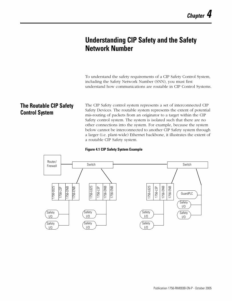
The CIP Safety control system represents a set of interconnected CIP Safety Devices. The routable system represents the extent of potential mis-routing of packets from an originator to a target within the CIP Safety control system. The system is isolated such that there are no other connections into the system. For example, because the system below cannot be interconnected to another CIP Safety system through a larger (i.e. plant-wide) Ethernet backbone, it illustrates the extent of a routable CIP Safety system.
Figure 4.1 CIP Safety System Example
1756
-L62
S
1756
-LSP
1756
-DN
B
1756
-ENB
1756
-L62
S
1756
-LSP
1756
-DNB
1756
-EN
B
Switch SwitchRouter/Firewall
Safety I/O
Safety I/O
Safety I/O
Safety I/O
GuardPLC
1756
-L62
S
1756
-LSP
1756
-DNB
1756
-EN
B
Safety I/O
Safety I/O
Safety I/O
Safety I/O
1 Publication 1756-RM093B-EN-P - October 2005
4-2 Understanding CIP Safety and the Safety Network Number
Unique Node Reference
The CIP Safety protocol is an end-node to end-node safety protocol. The CIP Safety protocol allows the routing of CIP Safety messages to and from CIP Safety devices through non-certified bridges, switches, and routers.
To prevent errors in non-certified bridges, switches, or routers from becoming dangerous, each end node within a routable CIP Safety Control System must have a unique node reference. The unique node reference is a combination of a Safety Network Number (SNN) and the Node Address of the node.
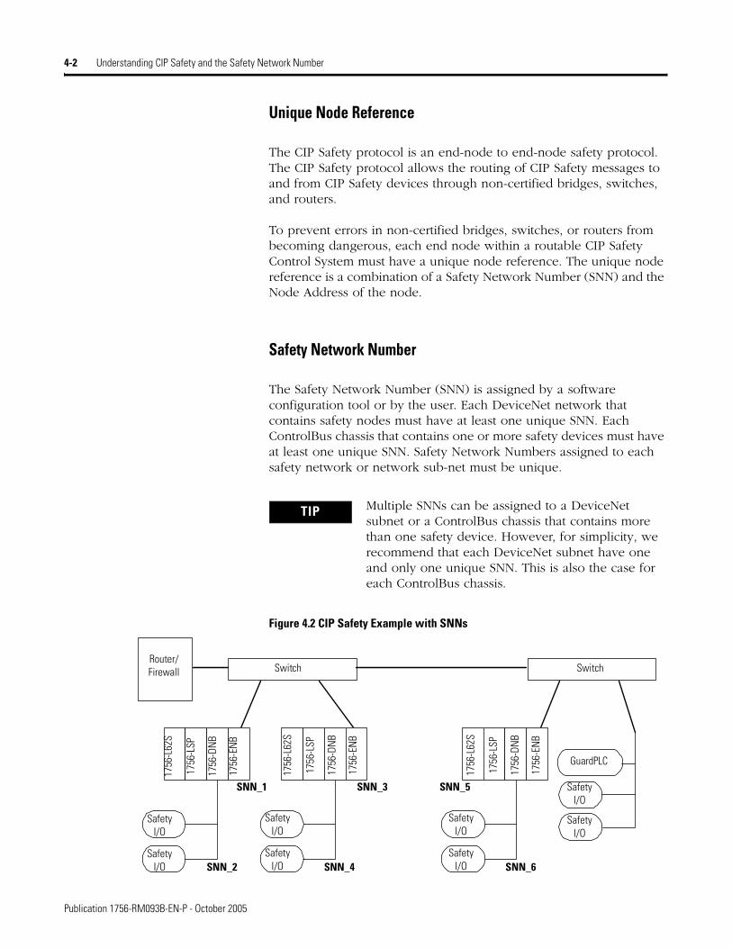
Safety Network Number
The Safety Network Number (SNN) is assigned by a software configuration tool or by the user. Each DeviceNet network that contains safety nodes must have at least one unique SNN. Each ControlBus chassis that contains one or more safety devices must have at least one unique SNN. Safety Network Numbers assigned to each safety network or network sub-net must be unique.
Figure 4.2 CIP Safety Example with SNNs
TIP Multiple SNNs can be assigned to a DeviceNet subnet or a ControlBus chassis that contains more than one safety device. However, for simplicity, we recommend that each DeviceNet subnet have one and only one unique SNN. This is also the case for each ControlBus chassis.
1756
-L62
S
1756
-LSP
1756
-DN
B
1756
-EN
B
1756
-L62
S
1756
-LSP
1756
-DN
B
1756
-ENB
Switch SwitchRouter/Firewall
Safety I/O
Safety I/O
Safety I/O
Safety I/O
GuardPLC
1756
-L62
S
1756
-LSP
1756
-DN
B
1756
-ENB
Safety I/O
Safety I/O
Safety I/O
Safety I/O
SNN_1 SNN_3 SNN_5
SNN_2 SNN_4 SNN_6
Publication 1756-RM093B-EN-P - October 2005
Understanding CIP Safety and the Safety Network Number 4-3
Each CIP Safety device must be configured with an SNN. Any device that originates a safety connection to another safety device must be configured with the SNN of the target device. If the CIP Safety System is in the start-up process prior to the functional safety testing of the system, the originating device may be used to set the unique node reference into the device.
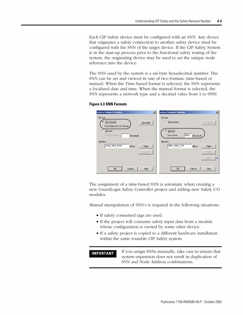
The SNN used by the system is a six-byte hexadecimal number. The SNN can be set and viewed in one of two formats: time-based or manual. When the Time-based format is selected, the SNN represents a localized date and time. When the manual format is selected, the SNN represents a network type and a decimal value from 1 to 9999.
Figure 4.3 SNN Formats
The assignment of a time-based SNN is automatic when creating a new GuardLogix Safety Controller project and adding new Safety I/O modules.
Manual manipulation of SNN’s is required in the following situations:
• If safety consumed tags are used.
• If the project will consume safety input data from a module whose configuration is owned by some other device.
• If a safety project is copied to a different hardware installation within the same routable CIP Safety system.
IMPORTANT If you assign SNNs manually, take care to ensure that system expansion does not result in duplication of SNN and Node Address combinations.
Publication 1756-RM093B-EN-P - October 2005
4-4 Understanding CIP Safety and the Safety Network Number
Considerations for Assigning the SNN
SNN for Safety Consumed Tags
When a safety controller that contains produced safety tags is added to the I/O Configuration tree, the SNN of the producing controller must be entered. The SNN may be copied from the producing controller’s project and pasted into the new controller being added to the I/O Configuration tree. Refer to the GuardLogix Controllers User Manual, publication number 1756-UM020, for information on how to copy and paste an SNN.
SNNs for Out-Of-Box Modules
The new SNN of an out-of-box DeviceNet Safety I/O module is set in that module the first time that it is connected to the safety system and prior to the Safety Signature being applied to the GuardLogix controller project.
SNN for Safety Module with a Different Configuration Owner
When a safety I/O module whose configuration is owned by some other device is added to the I/O Configuration tree, an SNN will automatically be assigned by RSLogix 5000. If the module’s configuration owner had already assigned an SNN to the module or network, the original SNN will need to be re-entered on the module’s Safety Network Number dialog. Refer to the GuardLogix Controllers User Manual, publication number 1756-UM020, for information on changing, copying, and pasting Safety Network Numbers.
IMPORTANT To allow the SNN to be set in the I/O modules, connect to the DeviceNet Safety I/O module prior to applying the Safety Signature to the safety controller project. The SNN assignment will then be tested as part of the normal safety verification that occurs after the Signature is applied and before the safety system is authorized.
Publication 1756-RM093B-EN-P - October 2005
Understanding CIP Safety and the Safety Network Number 4-5
SNNs when Copying a Safety Project
ATTENTION If a safety project is copied to another project intended for a different hardware installation and that installation may reside within the same routable CIP Safety System, the SNN must be changed, as described in the GuardLogix Controllers User Manual, publication number 1756-UM020, to ensure that SNN is not repeated.
Publication 1756-RM093B-EN-P - October 2005

4-6 Understanding CIP Safety and the Safety Network Number
Publication 1756-RM093B-EN-P - October 2005
Chapter 5
Characteristics of Safety Tags, the Safety Task, and Safety Programs
Differentiating Between Standard and Safety
Both standard (non-safety-related) and safety-related components can be used in the GuardLogix Control System. However, you must make a logical and visible distinction between the standard and safety-related portions of the application. RSLogix 5000 provides this differentiation via safety tags, the Safety Task, safety programs, and safety routines.
Using Safety Tags The GuardLogix Control System supports the use of both standard and safety tags in the same project. However, the programming software differentiates standard from safety tags, both visually and operationally.
Safety tags have all the attributes of standard tags with the addition of mechanisms to provide SIL 3 data integrity. You can declare safety tags of any valid data type. Tags that cannot be used as safety tags are those with the following data types:
• AXIS_CONSUMED
• AXIS_GENERIC
• AXIS_SERVO
• AXIS_SERVO_DRIVE
• AXIS_VIRTUAL
• MOTION_GROUP
• MESSAGE
• COORDINATE_SYSTEM
• REAL
Tags classified as safety tags must be either controller-scoped or safety-program-scoped. Safety-program-scoped safety tags can only be read by or written to via a safety routine scoped in the same safety program. Controller-scoped safety tags can be read, but not written to, by standard routines. As you develop your application logic, you must
IMPORTANT Aliasing between standard and safety tags is prohibited in safety applications.
1 Publication 1756-RM093B-EN-P - October 2005
5-2 Characteristics of Safety Tags, the Safety Task, and Safety Programs
differentiate safety controller-scoped tags from standard controller-scoped tags.
Tags associated with safety I/O and produced or consumed safety data must be controller-scoped safety tags.
Using Standard Tags in Safety Routines (Tag Mapping)
Controller-scoped standard tags can be mapped into safety tags, providing you with a mechanism to synchronize standard and safety actions. For information on how to map tags, see the GuardLogix Controllers User Manual, publication number 1756-UM020.
IMPORTANT Any controller-scoped safety tag is readable by any standard routine, but the update rate and time is based on the execution of the Safety Task. This means that safety tags are updated at the Safety Task periodic rate, not the network RPI.
Safety tag input data arrives at the controller based on the Safety Task RPI time. The range of the Safety Task RPI for safety inputs and safety consumed tags is 1 to 500 ms.
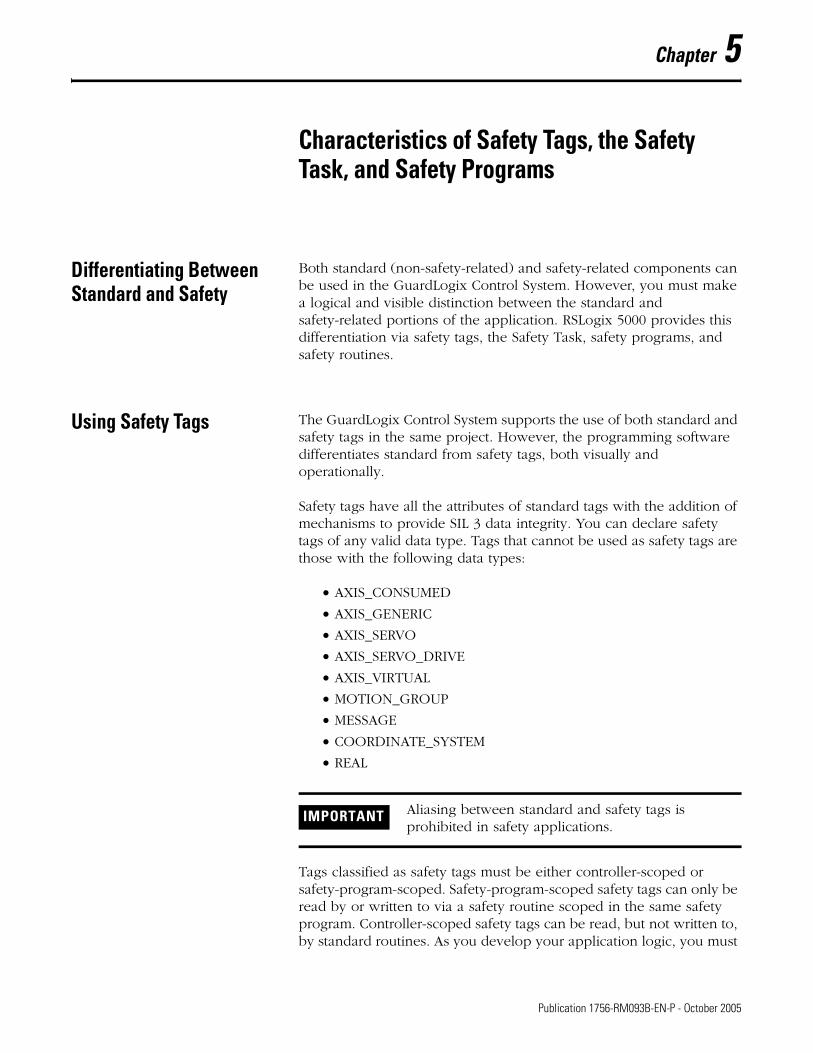
ATTENTION
!When using standard data in a safety routine, you are responsible for providing a reliable means of ensuring that the data is used in a safe manner. One way to do this is to qualify the standard data with safety data, as shown in the following example.
Figure 5.1 Qualifying Standard Data with Safety Data
ONSMappedBooleanTag LatchOneShot
Node30ComboModule:O.Pt03Data
Node30ComboModule:I.Pt07Data Node30ComboModule:O.Pt03Data
Latch circuit to prevent automatic restart if the standard input (MappedTag) is failed in a ‘stuck at 1’ state.
Safety input qualifier for mapped tag
Safety output
Publication 1756-RM093B-EN-P - October 2005
Characteristics of Safety Tags, the Safety Task, and Safety Programs 5-3
Understanding the Safety Task
Creation of a GuardLogix project automatically creates a single Safety Task. The Safety Task has these additional characteristics:
• The GuardLogix controller is the only controller that supports the Safety Task.
• The Safety Task cannot be deleted or inhibited.
• The GuardLogix controller supports a single Safety Task.
• Within the Safety Task, you can schedule multiple safety programs composed of multiple safety routines.
• You cannot schedule or execute standard routines from within the Safety Task.
The Safety Task is a periodic/timed task with a user-selectable task priority and watchdog. It should be the controller’s top priority and the user-defined program watchdog must be set to accommodate fluctuations in the execution of the Safety Task.
Safety Task Limitations
You specify both the Safety Task Period and the Safety Task Watchdog. The Safety Task Period is the period at which the Safety Task executes. The Safety Task Watchdog is the maximum time allowed from the start of Safety Task scheduled execution to its completion. For more information on the Safety Task Watchdog, see Appendix B, Reaction Times.
The Safety Task Period is limited to a maximum of 500 ms and cannot be modified online. Ensure that the Safety Task has enough time to finish before it is triggered again. Safety Task Watchdog Timeout, a non-recoverable safety fault in the GuardLogix controller, occurs if the Safety Task is triggered while it is still executing from the previous trigger. See Chapter 7, ‘Monitoring Status and Handling Faults’, for more information.
Publication 1756-RM093B-EN-P - October 2005
5-4 Characteristics of Safety Tags, the Safety Task, and Safety Programs
Safety Task Execution
The Safety Task executes in the same manner as standard periodic tasks, with the following exceptions:
• The Safety Task does not begin executing until the Primary Controller and Safety Partner have established their control partnership and the Coordinated System Time (CST) is synchronized. However, standard tasks begin executing as soon as the controller transitions to RUN mode.
• Safety input tags and safety-consumed tags are updated at the beginning of Safety Task execution.
• Safety input values are frozen at the start of Safety Task execution. As a result, timer-related instructions (e.g. TON, TOF, etc.) will not include time elapsed during a single Safety Task execution. They will keep accurate time from one task execution to another, but the time base will not change during the Safety Task execution.
• For standard tags that are mapped to safety tags, the standard tag values are copied into Safety Task memory at the start of Safety Task and do not change during execution.
• Safety-produced tags are produced at the conclusion of Safety Task execution.
• Safety output tags are sent to safety outputs at the conclusion of Safety Task execution.
• The Safety Task responds to mode changes (i.e. Run to Program or Program to Run) at timed intervals. As a result, the Safety Task may take more than one task period, but always less than two, to make a mode transition.
ATTENTION
!This behavior differs from standard task execution.
Publication 1756-RM093B-EN-P - October 2005
Characteristics of Safety Tags, the Safety Task, and Safety Programs 5-5
Safety Programs A safety program has all the attributes of a standard program, except that it can only be scheduled in the Safety Task. A safety program may also define program-scoped safety tags. A safety program may be scheduled or unscheduled.
A safety program can contain only safety components. All of the routines in a safety program must be safety routines. A safety program cannot contain standard routines or standard tags.
Safety Routines A safety routine has all the attributes of a standard routine, except that it can only exist in a safety program. One safety routine may be designated as the main routine. Another safety routine may be designated as the fault routine. Only safety instructions may be used in safety routines. For a listing of safety application instructions, see Appendix A.
IMPORTANT While Safety-Unlocked and without a Safety Signature, the controller prevents simultaneous write access to safety memory from the Safety Task and communications commands. As a result, the Safety Task can be held off until a communications update completes. The time required for the update varies by tag size. Therefore, safety connection and/or safety watchdog timeouts could occur. (For example, if you make online edits when the Safety Task rate is set to 1 ms, a safety watchdog timeout could occur.)
To compensate for the hold-off time due to a communications update, add 2 ms to the Safety Watchdog time.
NOTE: When the controller is Safety-Locked or a Safety Signature exists, this situation cannot occur.
ATTENTION
!To preserve SIL 3, you must ensure that your safety logic does not attempt to read or write standard tags.
Publication 1756-RM093B-EN-P - October 2005

5-6 Characteristics of Safety Tags, the Safety Task, and Safety Programs
Publication 1756-RM093B-EN-P - October 2005
Chapter 6
Safety Application Development
Safety Concept Assumptions
The safety concept assumes that:
1. those responsible for creating, operating, and maintaining the application are fully qualified, specially trained personnel, experienced in safety systems.
2. the user applies the logic correctly, meaning that programming errors can be detected. Programming errors can be detected by strict adherence to specifications, programming and naming rules.
3. the user performs a critical analysis of their application and uses all possible measures to detect a failure.
4. the user confirms all application downloads via a manual check of the Safety Signature.
5. before the initial startup of a safety-related system, the entire system is checked by a complete functional test.
Basics of Application Development and Testing
The application program for the intended SIL 3 system should be developed by the system integrator and/or user trained and experienced in safety applications. The developer must follow good design practices, including the use of:
• Functional specifications, including:
– Flow charts
– Timing diagrams
– Sequence charts
• Program review
• Program validation
1 Publication 1756-RM093B-EN-P - October 2005

6-2 Safety Application Development
Commissioning Life Cycle The flowchart below shows the steps required for commissioning a GuardLogix system. The items in bold text are explained in the following sections.
Figure 6.1 Commissioning the System
Specify the Control Function
Create Project Online
Create Project Offline
Attach to Controller and Download
Test the Application Program
Generate Safety Signature
Confirm the Project
Record Safety Signature
Project Verification Test
Safety Validation (Independent Review)
Lock the Controller / End
Make requiredmodifications
Delete Safety SignatureTestsPassed?
ProjectValid?
No
Yes
No
Yes
Fill out the Safety Checklists in Appendix C
Publication 1756-RM093B-EN-P - October 2005

Safety Application Development 6-3
Specification of the Control Function
You must create a specification for your control function. Use this specification to verify that program logic correctly and fully addresses your application’s functional and safety control requirements. The specification may be presented in a variety of formats, depending on your application. However, the specification must be a detailed description that includes (if applicable):
• Sequence of operations
• Flow and timing diagrams
• Sequence charts
• Program description
• Program print out
• Verbal descriptions of the steps with step conditions and actuators to be controlled, including:
– input definitions
– output definitions
– I/O wiring diagrams and references
– theory of operation
• Matrix or table of stepped conditions and the actuators to be controlled, including the sequence and timing diagrams
• Definition of marginal conditions, for example, operating modes, EMERGENCY STOP etc.
The I/O-portion of the specification must contain the analysis of field circuits, that is, the type of sensors and actuators:
• Sensors (Digital or Analog)
– Signal in standard operation (dormant current principle for digital sensors, sensors OFF means no signal)
– Determination of redundancies required for SIL levels
– Discrepancy monitoring and visualization, including the user’s diagnostic logic
• Actuators
– Position and activation in standard operation (normally OFF)
– Safe reaction/positioning when switching OFF or power failure.
– Discrepancy monitoring and visualization, including the user’s diagnostic logic
Publication 1756-RM093B-EN-P - October 2005
6-4 Safety Application Development
Create the Project
The logic and instructions used in programming the application must be:
• easy to understand
• easy to trace
• easy to change
• easy to test
All logic should be reviewed and tested. Keep safety-related logic and non-safety-related logic separate.
Label the Program
The application program is clearly identified by one of the following:
• Name
• Date
• Revision
• Any other user identification
Testing the Application Program
This step consists of any combination of Run and Program mode, online or offline edits, upload and download, and informal testing that is required to get an application running properly.
Generating the Safety Signature
To help ensure that a specific project is downloaded to the correct (target) controller, the GuardLogix controller and RSLogix 5000 support the creation of a Safety Signature. The Safety Signature uniquely identifies each project, including its logic, data, tags, etc. The safety signature is composed of an ID (identification number), date, and time.
Publication 1756-RM093B-EN-P - October 2005

Safety Application Development 6-5
You can generate the Safety Signature if all of the following conditions are true:
• the controller is online,
• the controller is in program mode,
• the controller is Safety-Unlocked,
• the controller has no safety forces or pending online safety edits, and
• the Safety Task status is OK.
Once application program testing is complete, you must generate the Safety Signature. The programming software automatically uploads the Safety Signature after it is generated.
You can delete the Safety Signature only when the GuardLogix controller is Safety-Unlocked and the controller is not in the Run mode (keyswitch in RUN position).
When a Safety Signature exists, the following actions are not permitted within the Safety Task:
• Online/offline programming or editing
• Forcing Safety I/O
• Data manipulation (except through routine logic)
Project Verification Test
To check the application program for adherence to the specification, you must generate a suitable set of test cases covering the application. The set of test cases must be filed and retained as the test specification.
You must include a set of tests to prove the validity of the calculations (formulas) used in your application logic. Equivalent range tests are acceptable. These are tests within the defined value ranges, at the limits, or in invalid value ranges. The necessary number of test cases depends on the formulas used and must comprise critical value pairs.
IMPORTANT To verify the integrity of every download, you must manually record the Safety Signature after initial creation and check the Safety Signature after every download to ensure that it matches the original.
Publication 1756-RM093B-EN-P - October 2005
6-6 Safety Application Development
Active simulation with sources (field devices) must also be included, since it is the only way to verify that the sensors and actuators in the system are wired correctly. Verify the operation of programmed functions by manually manipulating sensors and actuators.
You must also include tests to verify the reaction to wiring faults and network communication faults.
Project Verification includes required functional verification tests of fault routines, input and output channels, etc. to ensure that the safety system operates properly. See ‘Functional Verification Tests’ on page 1-2 for more information.
Confirm the Project
You must print or view the project, and manually compare the uploaded safety I/O and controller configurations, safety data, and safety task program logic to ensure that the correct safety components were downloaded, tested, and retained in the safety application program.
The steps below illustrate one method for confirming the project:
1. With the controller in Program mode, save the project. Answer ‘Yes’ to the Upload Tag Values prompt.
2. With RSLogix 5000 offline, save the project with a new name, such as ‘Offlineprojectname.ACD’, where projectname is the name of your project.
3. Close the project.
4. Rename the original project archive file to ‘Originalprojectname.ACD’, where projectname is the name of your project.
5. With the controller still in Program mode, upload the project from the controller.
Name the uploaded project ‘Onlineprojectname.ACD’, where projectname is the name of your project.
Answer ‘Yes’ to the Upload Tag Values prompt.
6. Invoke another instance of RSLogix 5000 and open the project named ‘Originalprojectname.ACD’.
Publication 1756-RM093B-EN-P - October 2005
Safety Application Development 6-7
7. Use the two instances of RSLogix 5000 to compare the following:
• all of the properties of the GuardLogix controller and DeviceNet Safety I/O modules
• all of the properties of the Safety Task, safety programs and safety routines
• all of the logic in the safety routines.
Safety Validation
An independent, third-party review of the safety system may be required before the system is approved for operation.
Locking the GuardLogix Controller
The GuardLogix Controller system can be Safety-Locked to protect safety control components from modification. The Safety-Lock feature applies only to safety components, such as the Safety Task, safety routines, safety I/O, Safety Signature, etc. However, Safety-Locking alone does not satisfy SIL 3 requirements.
No portion of a safety component can be modified while the controller is in the Safety-Locked state. When the controller is Safety-Locked, the following actions are not permitted in the Safety Task:
• Online/offline programming or editing
• Forcing safety I/O
• Data manipulation (except through routine logic)
• Generating or deleting the Safety Signature
The default state of the controller is Safety-Unlocked. You may place the controller in a Safety-Locked state regardless of whether the controller is online or offline, and regardless of whether you have the original source of the program. However, no safety forces or pending online safety edits may be present. Safety-Locked or -Unlocked status cannot be modified when the keyswitch is in the RUN position.
TIP RSLogix 5000 features a Program Compare utility that may be helpful in identifying changed safety components, but it must not be used in place of a manual compare.
Publication 1756-RM093B-EN-P - October 2005
6-8 Safety Application Development
To provide an additional layer of protection, separate passwords may be used for Safety-Locking or -Unlocking the controller. Passwords are optional.
Downloading the Safety Application Program
Upon download, full application testing is required unless a Safety Signature exists.
Downloads to a Safety-Locked GuardLogix controller are allowed only if the Safety Signature, the hardware series, and the OS version of the offline project all match those contained in the target GuardLogix controller and the controller’s Safety Task status is OK.
Uploading the Safety Application Program
If the GuardLogix controller contains a Safety Signature, the Safety Signature will be uploaded with the project. This means that any changes to offline data will be overwritten as a result of the upload.
Online Editing If there is no Safety Signature and the controller is Safety-Unlocked, you can perform online edits to your safety routines.
Pending edits cannot exist when the controller is Safety-Locked or when there is a Safety Signature. Online edits may exist when the controller is Safety-Locked. However, they may not be assembled, cancelled, etc.
See page 6-9 for more information on making edits to your application program.
IMPORTANT To verify the integrity of every download, you must manually record the Safety Signature after initial creation and check the Safety Signature after every download to ensure that it matches the original.
IMPORTANT If the Safety Signature does not match and the controller is Safety-Locked, you must unlock the controller to download. Downloading to the controller deletes the Safety Signature. As a result, you must re-validate the application.
TIP Online edits in standard routines are unaffected by the Safety-Locked or -Unlocked state.
Publication 1756-RM093B-EN-P - October 2005
Safety Application Development 6-9
Forcing All data contained in an I/O, produced, or consumed safety tag, including CONNECTION_STATUS, can be forced while the project is Safety-Unlocked and no Safety Signature exists. However, forces must be uninstalled, not just disabled, on all safety tags before the safety project can be Safety-Locked or a Safety Signature can be generated. You cannot force safety tags while the project is Safety-Locked or when a Safety Signature exists.
Inhibiting a Module Inhibiting a module is configured at the safety I/O module level. All modules on the branch past the inhibited module are also inhibited. If either a safety I/O module or a producer controller is inhibited, the consumed safety data for each connection is reset to 0.
You cannot inhibit or uninhibit Safety I/O modules or producer controllers if the application is Safety-Locked or a Safety Signature exists.
Changing Your Application Program
The following rules apply to changing your application program in RSLogix 5000:
• Only authorized, specially-trained personnel can make program edits. These personnel should use all supervisory methods available, for example, using the controller keyswitch and software password protections.
• When authorized, specially-trained personnel make program edits, they assume the central safety responsibility while the changes are in progress. These personnel must also maintain safe application operation.
• When editing online, you must use an alternate protection mechanism to maintain the safety of the system.
• You must sufficiently document all program edits, including:
– authorization
– impact analysis
– execution
– test information
– revision information
• If online edits exist in the standard routines only, those edits are not required to be validated before returning to normal operation.
TIP You can install and uninstall forces on standard tags regardless of the Safety-Locked or -Unlocked state.
Publication 1756-RM093B-EN-P - October 2005

6-10 Safety Application Development
• You must ensure that changes to the standard routine, with respect to timing and tag mapping, are acceptable to your safety application.
• You can edit the logic portion of your program while Offline or Online, as described in the following sections.
Performing Offline Edits
When offline edits are made to standard program elements only, and the Safety Signature matches following a download, you can resume operation.
When offline edits affect the safety program, you must revalidate the entire application before resuming operation.
The flowchart on page 6-11 illustrates the process for offline editing.
Performing Online Edits
If online edits affect the safety program, you must revalidate the entire application before resuming operation. The flowchart on page 6-11 illustrates the process for online editing.
Online edits are affected by the Safety-Lock and Safety Signature features of the GuardLogix controller. See ‘Generating the Safety Signature’ on page 6-4 and ‘Locking the GuardLogix Controller’ on page 6-7 for more information.
For detailed information on how to edit ladder logic in RSLogix 5000 while online, see the Logix5000 Controllers Quick Start, publication 1756-QS001.
TIP Limit online edits to minor program modifications such as setpoint changes or logic additions, deletions and modifications.
Publication 1756-RM093B-EN-P - October 2005
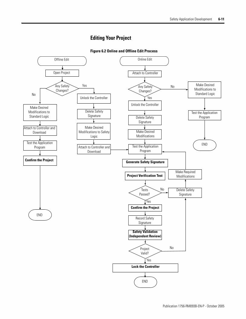
Safety Application Development 6-11
Editing Your Project
Figure 6.2 Online and Offline Edit Process
Generate Safety Signature
Confirm the Project
Record SafetySignature
Project Verification Test
Safety Validation(Independent Review)
Lock the Controller
Make RequiredModifications
Delete SafetySignature
TestsPassed?
ProjectValid?
No
Yes
No
Yes
Online Edit
Attach to Controller
Test the Application Program
Make DesiredModifications to Standard Logic
Any SafetyChanges?
Yes
No
Delete SafetySignature
Make DesiredModifications
Offline Edit
Open Project
Any SafetyChanges?
Yes
No
Delete SafetySignature
Make DesiredModifications to Safety
Logic
Attach to Controller and Download
Make DesiredModifications to Standard Logic
Attach to Controller and Download
Unlock the Controller
Unlock the Controller
END
END
END
Test the Application Program
Test the Application Program
Confirm the Project
Publication 1756-RM093B-EN-P - October 2005

6-12 Safety Application Development
Publication 1756-RM093B-EN-P - October 2005
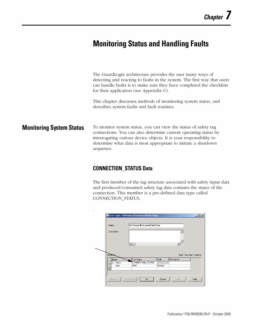
Chapter 7
Monitoring Status and Handling Faults
The GuardLogix architecture provides the user many ways of detecting and reacting to faults in the system. The first way that users can handle faults is to make sure they have completed the checklists for their application (see Appendix C).
This chapter discusses methods of monitoring system status, and describes system faults and fault routines.
Monitoring System Status To monitor system status, you can view the status of safety tag connections. You can also determine current operating status by interrogating various device objects. It is your responsibility to determine what data is most appropriate to initiate a shutdown sequence.
CONNECTION_STATUS Data
The first member of the tag structure associated with safety input data and produced/consumed safety tag data contains the status of the connection. This member is a pre-defined data type called CONNECTION_STATUS.
.
1 Publication 1756-RM093B-EN-P - October 2005

7-2 Monitoring Status and Handling Faults
The CONNECTION_STATUS data type contains RunMode and ConnectionFaulted status bits. The following table describes the combinations of the RunMode and ConnectionFaulted states.
Get System Value (GSV) and Set System Value (SSV) Instructions
The GSV and SSV instructions allow you to get (GSV) and set (SSV) controller system data stored in device objects. When you enter a GSV/SSV instruction, the programming software displays the valid object classes, object names, and attribute names for each instruction. Restrictions exist for using the GSV and SSV instructions with safety components.
Table 7.1 Safety Connection Status
RunMode Status equals:
ConnectionFaulted Status equals: Safety Connection Operation is
1 = Run 0 = Valid Data is actively being controlled by the producing device. The producing device is in Run mode.
0 = Idle 0 = Valid The connection is active and the producing device is in the Idle state. The safety data is reset to zero.
0 = Idle 1 = Faulted The safety connection is faulted. The state of the producing device is unknown. The safety data is reset to zero.
1 1 Invalid state.
ATTENTION
!Safety I/O connections and produced/consumed connections cannot be configured to fault the controller if a connection is lost and the system transitions to the safe state. Therefore, if you need to detect a module fault to ensure that the system maintains SIL 3, you must monitor the Safety I/O CONNECTION_STATUS bits and initiate the fault via program logic.
IMPORTANT The Safety Task cannot perform GSV or SSV operations on standard attributes.
The attributes of safety objects that can be written by the standard task are for diagnostic purposes only. They do not affect Safety Task execution.
Publication 1756-RM093B-EN-P - October 2005
Monitoring Status and Handling Faults 7-3
The GuardLogix Controllers User Manual, publication number 1756-UM020, provides information on which safety attributes are accessible via GSV and SSV instructions.
For more information on using GSV and SSV instructions, see the Logix5000 Controllers General Instructions Reference Manual, publication 1756-RM003.
GuardLogix System Faults Faults in the GuardLogix system fall into three categories:
• Non-recoverable Controller Faults
• Non-recoverable Safety Faults
• Recoverable Faults
These are explained in more detail in the following sections.
For information on handling faults, refer to the GuardLogix Controllers User Manual, publication number 1756-UM020.
Non-Recoverable Controller Faults
A non-recoverable controller fault occurs if the controller’s internal diagnostics fail. Partnership is lost when a non-recoverable controller fault occurs in either the Primary Controller or the Safety Partner, causing the other to generate a non-recoverable watchdog timeout fault. Standard task and Safety Task execution stops, and safety I/O transitions to the safe state.
Recovery from a non-recoverable controller fault requires re-download of the application program.
Non-Recoverable Safety Faults
In the event of a non-recoverable safety fault, the controller logs the fault to the controller-scoped fault handler and shuts down the Safety Task, including safety I/O and safety logic.
To recover from a non-recoverable safety fault, safety memory is re-initialized either from the Safety Signature (happens automatically when you clear the fault) or, if no Safety Signature exists, via an explicit download of the safety project.
Publication 1756-RM093B-EN-P - October 2005
7-4 Monitoring Status and Handling Faults
You can override the safety fault by clearing the fault log entry through the controller-scoped safety fault handler. This allows standard tasks to keep running.
Recoverable Faults
Controller faults caused by user programming errors in a safety program trigger the controller to process the logic contained in the project’s safety program fault handler. The safety program fault handler provides the application with the opportunity to resolve the fault condition and then recover.
When a safety program fault handler does not exist or the fault is not recovered by it, the controller processes the logic in the controller-scoped fault handler, terminating safety program logic execution and leaving safety I/O connections active, but idle.
If user logic is terminated as a result of a recoverable fault that is not recovered, safety outputs are placed in the safe state and the producer
ATTENTION
!Overriding the safety fault does not clear it! If you override the safety fault, it is your responsibility to prove that doing so maintains SIL 3.
ATTENTION
!You must provide proof to your certifying agency that automatic recovery from recoverable faults maintains SIL 3.
IMPORTANT When the execution of safety program logic is terminated due to a recoverable fault that is not handled by the safety program fault handler, the safety I/O connections are closed and re-opened to re-initialize safety connections.
Publication 1756-RM093B-EN-P - October 2005
Monitoring Status and Handling Faults 7-5
of safety-consumed tags commands the consumers to place them in a safe state.
If a recoverable safety fault is overridden in the controller-scoped fault handler, only standard tasks keep running. If the fault is not overridden, the standard tasks are also shut down.
TIP When using safety I/O for standard applications, safety I/O will be commanded to the safe state as a result of the above.
ATTENTION
!Overriding the safety fault does not clear it! If you override the safety fault, it is your responsibility to prove that doing so maintains SIL 3.
Publication 1756-RM093B-EN-P - October 2005

7-6 Monitoring Status and Handling Faults
Publication 1756-RM093B-EN-P - October 2005
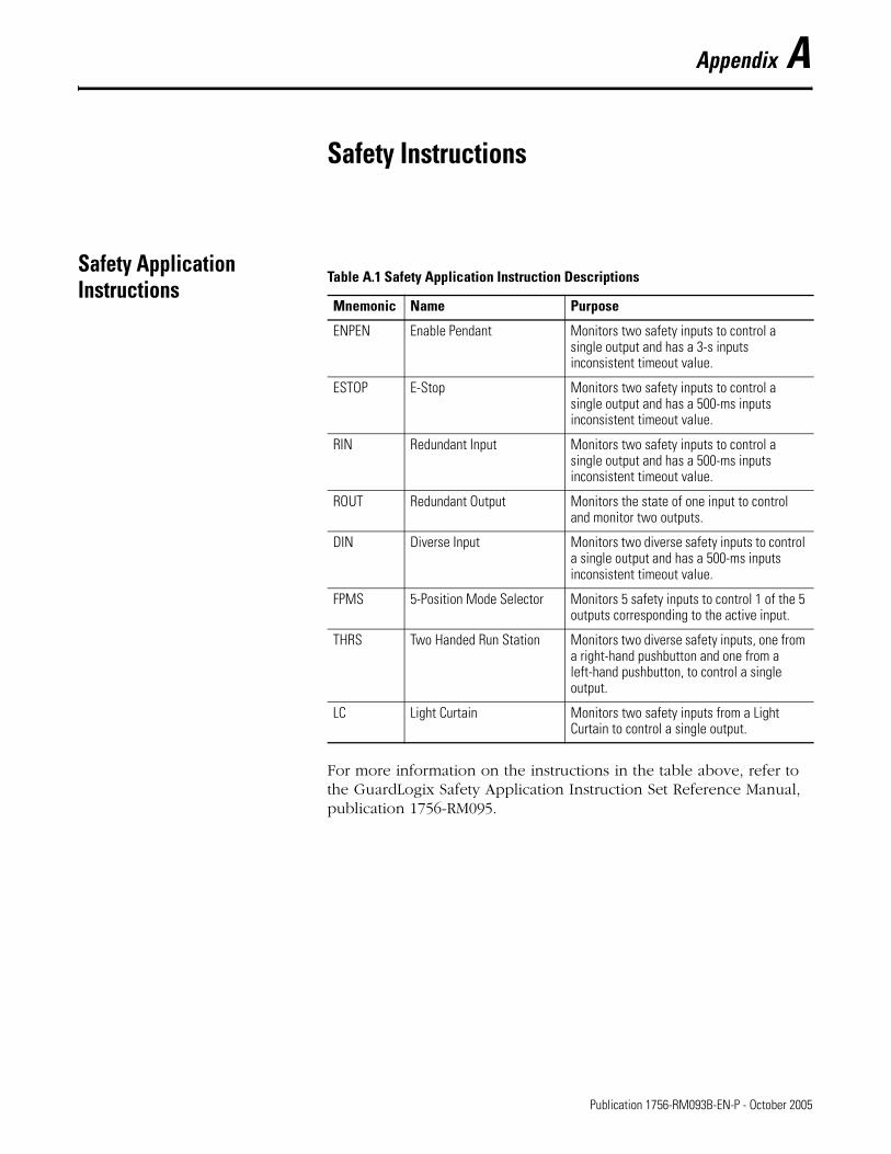
Appendix A
Safety Instructions
Safety Application Instructions
For more information on the instructions in the table above, refer to the GuardLogix Safety Application Instruction Set Reference Manual, publication 1756-RM095.
Table A.1 Safety Application Instruction Descriptions
Mnemonic Name Purpose
ENPEN Enable Pendant Monitors two safety inputs to control a single output and has a 3-s inputs inconsistent timeout value.
ESTOP E-Stop Monitors two safety inputs to control a single output and has a 500-ms inputs inconsistent timeout value.
RIN Redundant Input Monitors two safety inputs to control a single output and has a 500-ms inputs inconsistent timeout value.
ROUT Redundant Output Monitors the state of one input to control and monitor two outputs.
DIN Diverse Input Monitors two diverse safety inputs to control a single output and has a 500-ms inputs inconsistent timeout value.
FPMS 5-Position Mode Selector Monitors 5 safety inputs to control 1 of the 5 outputs corresponding to the active input.
THRS Two Handed Run Station Monitors two diverse safety inputs, one from a right-hand pushbutton and one from a left-hand pushbutton, to control a single output.
LC Light Curtain Monitors two safety inputs from a Light Curtain to control a single output.
1 Publication 1756-RM093B-EN-P - October 2005
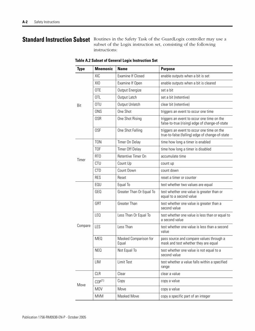
A-2 Safety Instructions
Standard Instruction Subset Routines in the Safety Task of the GuardLogix controller may use a subset of the Logix instruction set, consisting of the following instructions:
Table A.2 Subset of General Logix Instruction Set
Type Mnemonic Name Purpose
Bit
XIC Examine If Closed enable outputs when a bit is set
XIO Examine If Open enable outputs when a bit is cleared
OTE Output Energize set a bit
OTL Output Latch set a bit (retentive)
OTU Output Unlatch clear bit (retentive)
ONS One Shot triggers an event to occur one time
OSR One Shot Rising triggers an event to occur one time on the false-to-true (rising) edge of change-of-state
OSF One Shot Falling triggers an event to occur one time on the true-to-false (falling) edge of change-of-state
Timer
TON Timer On Delay time how long a timer is enabled
TOF Timer Off Delay time how long a timer is disabled
RTO Retentive Timer On accumulate time
CTU Count Up count up
CTD Count Down count down
RES Reset reset a timer or counter
Compare
EQU Equal To test whether two values are equal
GEQ Greater Than Or Equal To test whether one value is greater than or equal to a second value
GRT Greater Than test whether one value is greater than a second value
LEQ Less Than Or Equal To test whether one value is less than or equal to a second value
LES Less Than test whether one value is less than a second value
MEQ Masked Comparison for Equal
pass source and compare values through a mask and test whether they are equal
NEQ Not Equal To test whether one value is not equal to a second value
LIM Limit Test test whether a value falls within a specified range
Move
CLR Clear clear a value
COP(1) Copy copy a value
MOV Move copy a value
MVM Masked Move copy a specific part of an integer
Publication 1756-RM093B-EN-P - October 2005
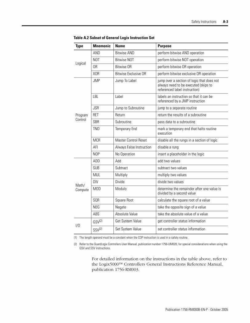
Safety Instructions A-3
For detailed information on the instructions in the table above, refer to the Logix5000™ Controllers General Instructions Reference Manual, publication 1756-RM003.
Logical
AND Bitwise AND perform bitwise AND operation
NOT Bitwise NOT perform bitwise NOT operation
OR Bitwise OR perform bitwise OR operation
XOR Bitwise Exclusive OR perform bitwise exclusive OR operation
Program Control
JMP Jump To Label jump over a section of logic that does not always need to be executed (skips to referenced label instruction)
LBL Label labels an instruction so that it can be referenced by a JMP instruction
JSR Jump to Subroutine jump to a separate routine
RET Return return the results of a subroutine
SBR Subroutine pass data to a subroutine
TND Temporary End mark a temporary end that halts routine execution
MCR Master Control Reset disable all the rungs in a section of logic
AFI Always False Instruction disable a rung
NOP No Operation insert a placeholder in the logic
Math/Compute
ADD Add add two values
SUB Subtract subtract two values
MUL Multiply multiply two values
DIV Divide divide two values
MOD Modulo determine the remainder after one value is divided by a second value
SQR Square Root calculate the square root of a value
NEG Negate take the opposite sign of a value
ABS Absolute Value take the absolute value of a value
I/OGSV(2) Get System Value get controller status information
SSV(2) Set System Value set controller status information
(1) The length operand must be a constant when the COP instruction is used in a safety routine.
(2) Refer to the GuardLogix Controllers User Manual, publication number 1756-UM020, for special considerations when using the GSV and SSV instructions.
Table A.2 Subset of General Logix Instruction Set
Type Mnemonic Name Purpose
Publication 1756-RM093B-EN-P - October 2005

A-4 Safety Instructions
Publication 1756-RM093B-EN-P - October 2005
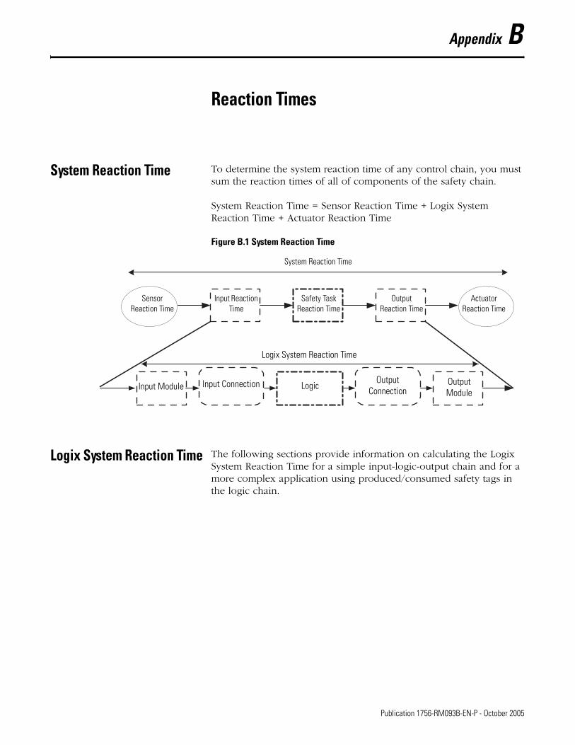
Appendix B
Reaction Times
System Reaction Time To determine the system reaction time of any control chain, you must sum the reaction times of all of components of the safety chain.
System Reaction Time = Sensor Reaction Time + Logix System Reaction Time + Actuator Reaction Time
Figure B.1 System Reaction Time
Logix System Reaction Time The following sections provide information on calculating the Logix System Reaction Time for a simple input-logic-output chain and for a more complex application using produced/consumed safety tags in the logic chain.
System Reaction Time
Sensor Reaction Time
Input Reaction Time
Safety Task Reaction Time
Output Reaction Time
Actuator Reaction Time
Logix System Reaction Time
Input Module Input Connection LogicOutput
ConnectionOutput Module
1 Publication 1756-RM093B-EN-P - October 2005
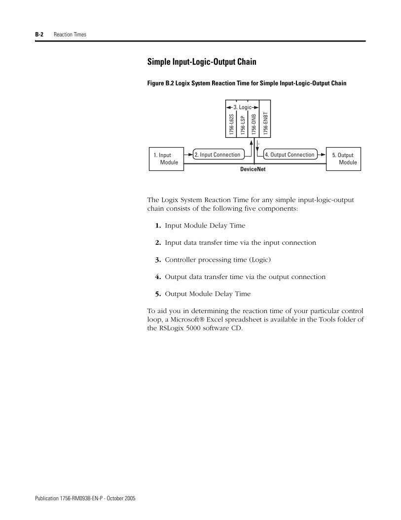
B-2 Reaction Times
Simple Input-Logic-Output Chain
Figure B.2 Logix System Reaction Time for Simple Input-Logic-Output Chain
The Logix System Reaction Time for any simple input-logic-output chain consists of the following five components:
1. Input Module Delay Time
2. Input data transfer time via the input connection
3. Controller processing time (Logic)
4. Output data transfer time via the output connection
5. Output Module Delay Time
To aid you in determining the reaction time of your particular control loop, a Microsoft® Excel spreadsheet is available in the Tools folder of the RSLogix 5000 software CD.
2. Input Connection
DeviceNet
3. Logic
1. Input Module
5. Output Module
4. Output Connection
1756
-L62
S
1756
-LSP
1756
-DN
B
1756
-EN
BT
Publication 1756-RM093B-EN-P - October 2005
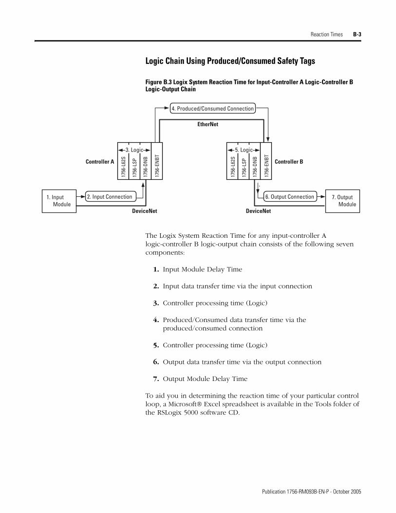
Reaction Times B-3
Logic Chain Using Produced/Consumed Safety Tags
Figure B.3 Logix System Reaction Time for Input-Controller A Logic-Controller B Logic-Output Chain
The Logix System Reaction Time for any input-controller A logic-controller B logic-output chain consists of the following seven components:
1. Input Module Delay Time
2. Input data transfer time via the input connection
3. Controller processing time (Logic)
4. Produced/Consumed data transfer time via the produced/consumed connection
5. Controller processing time (Logic)
6. Output data transfer time via the output connection
7. Output Module Delay Time
To aid you in determining the reaction time of your particular control loop, a Microsoft® Excel spreadsheet is available in the Tools folder of the RSLogix 5000 software CD.
2. Input Connection
DeviceNet DeviceNet
EtherNet
Controller A Controller B
3. Logic
1. Input Module
7. Output Module
6. Output Connection
4. Produced/Consumed Connection
1756
-L62
S
1756
-LSP
1756
-DN
B
1756
-EN
BT5. Logic
1756
-L62
S
1756
-LSP
1756
-DN
B
1756
-EN
BT
Publication 1756-RM093B-EN-P - October 2005
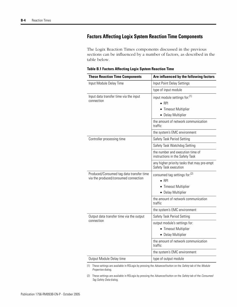
B-4 Reaction Times
Factors Affecting Logix System Reaction Time Components
The Logix Reaction Times components discussed in the previous sections can be influenced by a number of factors, as described in the table below.
Table B.1 Factors Affecting Logix System Reaction Time
These Reaction Time Components Are influenced by the following factors
Input Module Delay Time Input Point Delay Settings
type of input module
Input data transfer time via the input connection
input module settings for:(1)
• RPI
• Timeout Multiplier
• Delay Multiplier
(1) These settings are available in RSLogix by pressing the Advanced button on the Safety tab of the Module Properties dialog.
the amount of network communication traffic
the system’s EMC environment
Controller processing time Safety Task Period Setting
Safety Task Watchdog Setting
the number and execution time of instructions in the Safety Task
any higher priority tasks that may pre-empt Safety Task execution
Produced/Consumed tag data transfer time via the produced/consumed connection
consumed tag settings for:(2)
• RPI
• Timeout Multiplier
• Delay Multiplier
(2) These settings are available in RSLogix by pressing the Advanced button on the Safety tab of the Consumed Tag Safety Data dialog.
the amount of network communication traffic
the system’s EMC environment
Output data transfer time via the output connection
Safety Task Period Setting
output module’s settings for:
• Timeout Multiplier
• Delay Multiplier
the amount of network communication traffic
the system’s EMC environment
Output Module Delay time type of output module
Publication 1756-RM093B-EN-P - October 2005
Reaction Times B-5
For more information… The GuardLogix Controllers User Manual, publication number 1756-UM020, contains information on configuring delay times and reaction time limits for the input connection, Safety Task, and output connection.
For reaction times associated with DeviceNet Safety I/O modules, consult the product documentation for your specific module.
Publication 1756-RM093B-EN-P - October 2005

B-6 Reaction Times
Publication 1756-RM093B-EN-P - October 2005
Appendix C
Checklists for GuardLogix Safety Applications
The checklists in this Appendix are required for planning, programming and start-up of a SIL 3-certified GuardLogix application. They may be used as planning guides as well as during functional verification testing. If used as planning guides, the checklists can be saved as a record of the plan.
The checklists on the following pages provide a sample of safety considerations and are not intended to be a complete list of items to verify. Your particular safety application may have additional safety requirements, for which we have provided space in the checklists.
1 Publication 1756-RM093B-EN-P - October 2005
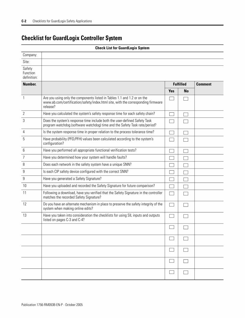
C-2 Checklists for GuardLogix Safety Applications
Checklist for GuardLogix Controller SystemCheck List for GuardLogix System
Company:
Site:
Safety Function definition:
Number. Fulfilled Comment
Yes No
1 Are you using only the components listed in Tables 1.1 and 1.2 or on the www.ab.com/certification/safety/index.html site, with the corresponding firmware release?
2 Have you calculated the system’s safety response time for each safety chain?
3 Does the system’s response time include both the user-defined Safety Task program watchdog (software watchdog) time and the Safety Task rate/period?
4 Is the system response time in proper relation to the process tolerance time?
5 Have probability (PFD/PFH) values been calculated according to the system’s configuration?
6 Have you performed all appropriate functional verification tests?
7 Have you determined how your system will handle faults?
8 Does each network in the safety system have a unique SNN?
9 Is each CIP safety device configured with the correct SNN?
9 Have you generated a Safety Signature?
10 Have you uploaded and recorded the Safety Signature for future comparison?
11 Following a download, have you verified that the Safety Signature in the controller matches the recorded Safety Signature?
12 Do you have an alternate mechanism in place to preserve the safety integrity of the system when making online edits?
13 Have you taken into consideration the checklists for using SIL inputs and outputs listed on pages C-3 and C-4?
Publication 1756-RM093B-EN-P - October 2005
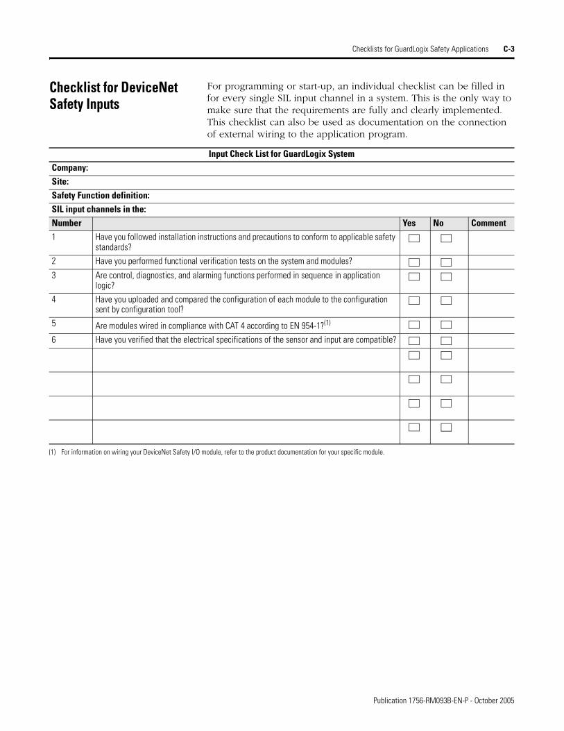
Checklists for GuardLogix Safety Applications C-3
Checklist for DeviceNet Safety Inputs
For programming or start-up, an individual checklist can be filled in for every single SIL input channel in a system. This is the only way to make sure that the requirements are fully and clearly implemented. This checklist can also be used as documentation on the connection of external wiring to the application program.
Input Check List for GuardLogix SystemCompany:Site:Safety Function definition:SIL input channels in the:Number Yes No Comment1 Have you followed installation instructions and precautions to conform to applicable safety
standards?
2 Have you performed functional verification tests on the system and modules?
3 Are control, diagnostics, and alarming functions performed in sequence in application logic?
4 Have you uploaded and compared the configuration of each module to the configuration sent by configuration tool?
5 Are modules wired in compliance with CAT 4 according to EN 954-1?(1)
6 Have you verified that the electrical specifications of the sensor and input are compatible?
(1) For information on wiring your DeviceNet Safety I/O module, refer to the product documentation for your specific module.
Publication 1756-RM093B-EN-P - October 2005
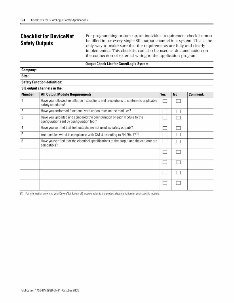
C-4 Checklists for GuardLogix Safety Applications
Checklist for DeviceNet Safety Outputs
For programming or start-up, an individual requirement checklist must be filled in for every single SIL output channel in a system. This is the only way to make sure that the requirements are fully and clearly implemented. This checklist can also be used as documentation on the connection of external wiring to the application program.
Output Check List for GuardLogix System
Company:
Site:
Safety Function definition:
SIL output channels in the:
Number All Output Module Requirements Yes No Comment:
1 Have you followed installation instructions and precautions to conform to applicable safety standards?
2 Have you performed functional verification tests on the modules?
3 Have you uploaded and compared the configuration of each module to the configuration sent by configuration tool?
4 Have you verified that test outputs are not used as safety outputs?
5 Are modules wired in compliance with CAT 4 according to EN 954-1?(1)
6 Have you verified that the electrical specifications of the output and the actuator are compatible?
(1) For information on wiring your DeviceNet Safety I/O module, refer to the product documentation for your specific module.
Publication 1756-RM093B-EN-P - October 2005

Checklists for GuardLogix Safety Applications C-5
Checklist for Developing a Safety Application Program
Use the following checklist to help maintain safety when creating or modifying a safety application program.
Check List for GuardLogix Application Program Development
Company:
Site:
Project definition:
Number Fulfilled Comment
Yes No
1 Are you using version 14 or higher of RSLogix 5000, the GuardLogix system programming software?
2 Were the programming guidelines in Chapter 6 followed during creation of the safety application program?
3 Does the safety application program contain only relay ladder logic?
4 Does the safety application program contain only those instructions listed in Appendix A as suitable for safety application programming?
5 Does the safety application program clearly differentiate between safety and standard tags?
6 Are only safety tags used for safety routines?
7 Have you verified that safety routines do not attempt to read from or write to standard tags?
8 Have you verified that no safety tags are aliased to standard tags and vice versa?
9 Is each output safety tag correctly configured and connected to a physical output channel?
10 Have you verified that all mapped tags have been conditioned in safety application logic?
11 Have you defined the process parameters that are monitored by fault routines?
12 Has the program been reviewed by an independent safety reviewer (if required)?
13 Has the review been documented and signed?
Publication 1756-RM093B-EN-P - October 2005

C-6 Checklists for GuardLogix Safety Applications
Publication 1756-RM093B-EN-P - October 2005
Glossary
Assemble Edits
This action is taken by the user when they have made online edit changes to the GuardLogix controller and want the changes to become permanent since the user can test, un-test, or cancel the edits.
Cancel Edits
Action taken by the user to reject any unassembled online edit changes.
CIP Safety Protocol
A network communications method designed and certified for transport of data with high integrity.
Configuration Signature
A unique number that identifies a device’s configuration. The Configuration Signature is made up of an ID number, date, and time.
Non-recoverable Controller Fault
A fault that forces all processing to be terminated and requires controller power to be cycled from off to on. The user program is not preserved and must be re-downloaded.
Non-recoverable Safety Fault
A fault, which even though properly handled by the fault handling mechanisms provided by the GuardLogix controller and implemented by the user, terminates all Safety Task processing, and requires external user action to restart the Safety Task.
Online
Situation where the user is monitoring/modifying the program in the GuardLogix controller.
Overlap
When a task (periodic or event) is triggered while the task is still executing from the previous trigger.
Partnership
The Primary Controller and Safety Partner must both be present, and the hardware and firmware must be compatible for partnership to be established.
1 Publication 1756-RM093B-EN-P - October 2005
2 Glossary
Pending Edit
A change to a routine that has been made in RSLogix 5000 software, but has not yet been communicated to the controller by accepting the edit.
Periodic Task
A task that is triggered by the operating system at a repetitive period of time. Whenever the time expires, the task is triggered and its programs are executed. Data and outputs established by the programs in the task retain their values until the next execution of the task or until they are manipulated by another task. Periodic tasks always interrupt the continuous task.
Primary Controller
The processor in a dual-processor controller that performs standard controller functionality and communicates with the Safety Partner to perform safety-related functions.
Recoverable Fault
A fault, which when properly handled by the fault handling mechanisms provided by the GuardLogix controller and implemented by the user, does not force user logic execution to be terminated.
Requested Packet Interval (RPI)
When communicating over a network, this is the maximum amount of time between subsequent production of input data.
Routine
A set of logic instructions in a single programming language, such as a ladder diagram. Routines provide executable code for the project in a controller. Each program has a main routine. You can also specify optional routines.
Safety Application Instructions
Safety Instructions which provide safety-related functionality. They have been certified to SIL 3 for use in safety routines.
Safety Component
Any object, task, program, routine, tag, module, etc., that is marked as a safety-related item.
Publication 1756-RM093B-EN-P - October 2005
Glossary 3
Safety I/O
Safety I/O has most of the attributes of Standard I/O except it features mechanisms certified to SIL 3 to ensure data integrity.
Safety Network Number (SNN)
Uniquely identifies a network across all networks in the safety system. The end user is responsible is responsible for assigning a unique number for each safety network or safety sub-net within a system. The Safety Network Number makes up part of the Unique Node Identifier (UNID).
Safety Partner
The processor in a dual-processor controller that works with the Primary Controller to perform safety-related functions.
Safety Program
A Safety Program has all the attributes of a standard program, except that it can only be scheduled in a Safety Task. The safety program consists of zero or more safety routines. It cannot contain standard routines or standard tags.
Safety Routine
A safety routine has all the attributes of a standard routine except that it is valid only in a safety program and that it consists of one or more instructions suitable for safety applications (See Appendix A for a list of Safety Application Instructions and standard Logix Instructions that may be used in safety routine logic.)
Safety Signature
A value, calculated by the firmware, that uniquely represents the logic and configuration of the safety system. It is used to ensure the integrity of the safety application program during downloads to the controller.
Safety Tags
A safety tag has all the attributes of a standard tag except that the GuardLogix controller provides mechanisms certified to SIL 3 to ensure the integrity of their associated data. They can be program-scoped or controller-scoped.
Publication 1756-RM093B-EN-P - October 2005

4 Glossary
Safety Task
A Safety Task has all the attributes of a standard task except that it is valid only in a GuardLogix controller and that it may schedule only safety programs. Only one Safety Task can exist in a GuardLogix controller. The Safety Task must be a periodic/timed task.
Safety Task Period
The period at which the Safety Task executes.
Safety Task Reaction Time
The sum of the Safety Task Period plus the Safety Task Watchdog. This time represents the worst case delay from any input change presented to the GuardLogix controller until the processed output is available to the producing connection.
Safety Task Watchdog
The maximum time allowed from the start of Safety Task execution to its completion. Exceeding the Safety Task Watchdog triggers a non-recoverable safety fault.
Standard Component
Any object, task, tag, program, etc., that is NOT marked as being a safety-related item.
Standard Controller
As used in this document, standard controller refers generically to a ControlLogix controller.
Symbolic Addressing
A method of addressing which provides an ASCII interpretation of the tag name.
System Reaction Time
The worst case time from a safety-related event as input to the system or as a fault within the system, until the time that the system is in the safe state. System Reaction Time includes sensor and activator Reaction Times as well as the Controller Reaction Time.
Task
A scheduling mechanism for executing a program. A task provides scheduling and priority information for a set of one or more programs
Publication 1756-RM093B-EN-P - October 2005
Glossary 5
that execute based on a certain criteria. Once a task is triggered (activated), all of the programs assigned (scheduled) to the task execute in the order in which they are displayed in the controller organizer.
Timeout Multiplier
This value determines the number of messages that may be lost before declaring a connection error.
Valid Connection
Safety connection is open and active, with no errors.
Publication 1756-RM093B-EN-P - October 2005

6 Glossary
Notes:
Publication 1756-RM093B-EN-P - October 2005
Index
Numerics1756-A10 1-4, 1-51756-A13 1-4, 1-51756-A17 1-4, 1-51756-A4 1-4, 1-51756-A7 1-4, 1-51756-DNB
firmware revision 1-4hardware overview 2-3
1756-ENBTfirmware revision 1-4hardware overview 2-3
1756-PA72 1-4, 1-51756-PA75 1-4, 1-51756-PA75R 1-4, 1-51756-PB72 1-4, 1-51756-PB75 1-4, 1-51756-PB75R 1-4, 1-5
Aagency certifications 1-6application development basics 6-1application program
see program
Ccertifications 1-5chassis
catalog numbers 1-4hardware overview 2-2
checklistGuardLogix controller system 2-4, C-2program development C-5SIL 3 Inputs C-3SIL 3 outputs C-4
CIP safety protocoldefinition 1-1overview 2-3routable system 4-1
commissioning life cycle 6-2communication bridges
hardware overview 2-3communication modules
catalog numbers 1-4configuration signature 3-6connection status 7-2CONNECTION_STATUS
data type 7-1contact information 1-10
control and information protocolDefinition P-2
control functionspecification 6-3
DDeviceNet Safety
communications overview 2-4DeviceNet Scanner Interface Module
hardware overview 2-3diagnostic coverage
Definition P-2
EEN954-1
CAT 4 P-1, 1-1EtherNet/IP
communications overview 2-3EtherNet/IP Communication Interface
Modulehardware overview 2-3
European norm.Definition P-2
Ffailure
contact information 1-10faults
non-recoverable controller faults 7-3non-recoverable safety faults 7-3overriding 7-4recoverable 7-4
forcing 6-9fraction of detected common cause
failures 1-7fraction of undetected common cause
failures 1-7
Gget system value (GSV)
defintion P-2GSV instructions 7-2
Hhard faults
recovery 7-3hardware fault tolerance 1-7
Publication 1756-RM093B-EN-P - October 2005
2 Index
II/O modules
replacement 3-7–3-8IEC 61508
SIL 3 certification P-1, 1-1inhibiting a module 6-9installing a controller 2-1instructions
safety application A-1standard subset A-2
LLogix components
SIL 3-certified 1-4Logix instruction set A-2Logix system reaction time
calculating B-2
Mmapping tags 5-2
Nnon-recoverable controller fault
definition 1-1non-recoverable controller faults 7-3non-recoverable safety fault 1-1non-recoverable safety faults 7-3
re-starting the safety task 7-3
Ooffline edits 6-10online
definition 1-1online editing 6-8, 6-10Output Delay Time 3-5overlap
definition 1-1ownership 3-6
Ppartnership
definition 1-1peer-to-peer communications 2-3pending edits 6-8period task
definition 1-2
PFDSee probability of failure on demand.
PFHSee probability of failure per hour.
power supplies 1-4hardware overview 2-2SIL 3-certified 2-2
primary controllerdefinition 1-2hardware overview 2-1
probability of failure on demand (PFD) 1-6–1-8
definition P-2probability of failure per hour (PFH) 1-6–
1-8definition P-2
programchecklist C-5download 6-8editing life cycle 6-11offline editing 6-10online editing 6-10upload 6-8
program compare utility 6-7program indentification 6-4program verification 6-5programming software 1-2project
confirmation 6-6proof test interval
in PFD and PFH calculations 1-7Proof tests 1-2proof tests 1-2
Qqualifying standard data 5-2
Rreaction time
safety task 1-10system 1-9
recoverable faultdefinition 1-2
recoverable faults 7-4reliability burden 1-8requested packet interval
definition 1-2
Publication 1756-RM093B-EN-P - October 2005
Index 3
RSLogix 5000changing your application program 6-9commissioning life cycle 6-2revision 1-4
Ssafe failure fraction 1-7safety application instructions A-1
definition 1-2safety certifications and compliances
1-5safety concept
assumptions 6-1safety consumed tags
safety network number 4-4Safety Functions
DeviceNet Safety I/O 3-1Safety Output 3-5
safety network number 4-2definition 1-3manual assignment 4-2out-of-box modules 4-4safety consumed tags 4-4
safety partnerconfiguration 2-2definition 1-3hardware overview 2-2location 2-2
safety program 5-5definition 1-3
safety routine 5-5definition 1-3
Safety Signaturedefinition 1-3deleting 6-5generating 6-4restricted operations 6-5
safety tags 5-1definition 1-3invalid data types 5-1
safety taskdefinition 1-4execution 5-4overview 5-3
safety task period 1-10definition 1-4limitations 5-3overview 1-10
safety task reaction time 1-10definition 1-4
safety task watchdog 1-10definition 1-4modifying 1-10overview 1-10setting via RSLogix 5000 1-10
safety task watchdog timeout 5-3Safety-Locking 6-7
default 6-7passwords 6-8restricted operations 6-7
SIL 3 certification P-1, 1-1Logix components 1-4TÜV Rheinland 1-2user responsibilities 1-2
SIL complianceDistribution and weight 1-8
SIL function example 1-3SIL policy 1-1–1-10software
changing your application program 6-9commissioning life cycle 6-2
SSV instruction 7-2standard instructions A-2system reaction time 1-9
calculating B-1definition 1-4
Ttags
produced/consumed safety data 5-1safety I/O 5-1
terminologyused throughout manual P-2
timeout multiplierdefinition 1-5
Uunique node reference
defined 4-2
Publication 1756-RM093B-EN-P - October 2005

4 Index
Publication 1756-RM093B-EN-P - October 2005

Publication 1756-RM093B-EN-P - October 2005 5Supersedes Publication 1756-RM093A-EN-P - January 2005 Copyright © 2005 Rockwell Automation, Inc. All rights reserved. Printed in the U.S.A.
Rockwell Automation Support
Rockwell Automation provides technical information on the web to assist you in using its products. At http://support.rockwellautomation.com, you can find technical manuals, a knowledge base of FAQs, technical and application notes, sample code and links to software service packs, and a MySupport feature that you can customize to make the best use of these tools.
For an additional level of technical phone support for installation, configuration and troubleshooting, we offer TechConnect Support programs. For more information, contact your local distributor or Rockwell Automation representative, or visit http://support.rockwellautomation.com.
Installation Assistance
If you experience a problem with a hardware module within the first 24 hours of installation, please review the information that's contained in this manual. You can also contact a special Customer Support number for initial help in getting your module up and running:
New Product Satisfaction Return
We test all of our products to ensure that they are fully operational when shipped from the manufacturing facility. However, if your product is not functioning and needs to be returned:
United States 1.440.646.3223Monday – Friday, 8am – 5pm EST
Outside United States
Please contact your local Rockwell Automation representative for any technical support issues.
United States Contact your distributor. You must provide a Customer Support case number (see phone number above to obtain one) to your distributor in order to complete the return process.
Outside United States
Please contact your local Rockwell Automation representative for return procedure.