Embed Size (px)
Citation preview

Guarding of MachineryGuidance from the Quarry Products AssociationAugust 2005
www.qpa.org

Historically, a persistent feature of all industries operating
machinery and equipment has been the many injuries -
including fatalities - caused by the inadequacy or absence
of guarding.
Although standards have improved significantly, it remains
a fact that - for some - the basic principles are still not
sufficiently understood, implemented or maintained.
The Health and Safety Executive welcomes, therefore, the
publication of this richly illustrated Industry Guidance
which is an evolution of its predecessor published by
BACMI (the forerunner of the QPA).
The Quarrying Industry has made tremendous strides in
recent years in its quest to improve the health and safety
of its workforce. This publication is a further example of the
Industry's resolve to maintain this positive impetus, and as
such I commend it to you.
Preface
James Barrett
Head of Manufacturing Sector
Health and Safety Executive
1 Introduction
2 Guarding Life Cycle
2.1 Flow Chart
2.2 Design
2.3 Installation
2.4 Cleaning, maintenance, repair and adjustment
2.5 Re-design
3 Principles of Safe Guarding
Contents

1
Since the publication of the predecessor to
this Guide, there have been many legislative
changes, including :-
• The Supply of Machinery (Health and
Safety) Regulations 1992;
• The Provision and Use of Work Equipment
Regulations 1998; and
• The Quarries Regulations 1999.
British and European Standards have also been
updated accordingly.
The principal factors in many machinery
related injuries are poor design of guards;
inadequate provision for cleaning and
maintenance; and inappropriate construction
of guards for the working environment.
As a vital component of the competence of
everyone within the industry, training as to the
importance of machinery guarding cannot be
over emphasised. This is of particular relevance
to ensuring that machinery with missing or
defective guarding is not operated.
Everyone in the ‘life cycle’ has a part to play
to improve safety, i.e. designers, manufacturers,
suppliers, installers, users and
maintenance staff.
This document:
• aims to provide practical guidance on the
effective guarding of machinery typically
found in quarries, asphalt, concrete and
mortar plants, recycling and other
related activities.
• has relevance to fixed processing plant,
mobile processing plant and mobile
vehicular plant.
• should not be regarded as fully
comprehensive as other methods of
guarding may be applicable to
particular situations.
Neither the Quarry Products Association
nor its Members accept responsibility for
any acts or omissions arising from the use of
this Guide.
Introduction11
2
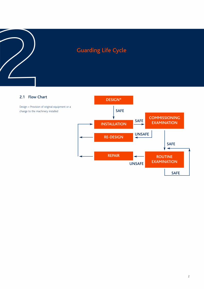
2.1 Flow Chart
Design = Provision of original equipment or a
change to the machinery installed
DESIGN*
Guarding Life Cycle22COMMISSIONING
EXAMINATIONINSTALLATION
RE-DESIGN
REPAIR ROUTINEEXAMINATION
SAFE
SAFE
SAFE
SAFE
UNSAFE
UNSAFE
3
2.3 Installation
Fixed close guards
• Must be held in place by fastenings which
require a tool to release them. This
excludes cable ties and wire or other such
bindings.
• Where possible, should not remain in place
once their fastenings are removed
Perimeter/ Distance Guards
• Guards should be secured to a solid
foundation or adjacent structure.
• Be equipped with a suitable interlocking
device to prevent moving parts starting up
whilst these parts can be accessed. Electrical
interlocks must be on mains voltage, not
control voltage, though this may not be
possible due to the configuration of certain
electrical installations.
All guards
• Where possible, to be installed to allow
routine adjustment and maintenance of the
guarded machinery without the need to
remove the guard. If this is not possible,
then a strict safe system of work should be
enforced.
• Be subject to an initial commissioning
examination and subsequent routine
inspection regime to ensure they are - and
remain - fit for purpose
2.2 Design
All guards should be designed to be fit for
purpose. Principal features to include:-
• Robust construction
• Use of sound materials
• Be suitable for the conditions in which they
are used
• To allow moving machinery to be seen,
where necessary
• Avoid the introduction of additional risks
• Endeavour to prevent by-pass or rendering
non-operational
• Be designed, located and installed to ensure
that access is prevented by any person, their
body parts or clothing.
NB: Where guards are fitted to the underside
of conveyors there may be a risk of spillage
accumulating within the guard. In such
situations, the guard mesh should be of a size
sufficient to allow spillage to fall through
(where safe to do so) whilst preventing access
to the moving parts within the guard.
Guarding Life Cycle22
4
padlock to the multi-hasp to ensure the
equipment remains locked between the shift
change.
2.5 Re-design
• All guards should be repaired or replaced if
they are damaged or changes to machinery
render them ineffective
• Under no circumstances should machinery
operate if guards are removed or damaged
2.4 Cleaning, maintenance,repair and adjustment
Before the removal of guards for the purpose
of carrying out cleaning, maintenance or
adjustment on any machinery, the power
source should be isolated and locked off.
Isolation and lock off should be considered
from ALL forms of energy in static and mobile
plant, i.e.:
• Electrical
• Pneumatic
• Hydraulic
• Mechanical
All forms of stored (‘potential’) energy should
be assessed and safely dissipated/released/
locked before the removal of guards from
machinery.
Before working on any electrical apparatus or
opening any electrical panel/enclosure where
live conductors may be exposed, the power
source shall be isolated. (An exemption to the
above rule may be made where a fully
qualified electrician is required to carry out live
testing under a permit to work system).
All relevant personnel shall be trained in
isolation and lock-off procedures to include a
practical demonstration of the isolation and
lock off. On completion of training, a record of
training shall be completed and filed.
Isolation lock off shall only be carried out
by individuals using their own personal
isolation padlocks.
When entering guarded enclosures personnel
must fit their own personal isolation padlocks,
even where a key exchange system is
operational. When personal locks are installed
these must prevent guard openings or access
gates being closed and re-energised.
Automatic isolation systems such as ‘key
exchange systems’, which disconnect all three
electrical phases, may be considered to provide
effective electrical isolation, and may be used
for repeated activities of short duration inside
guarded enclosures.
Where it is necessary for numbers of personnel
to enter guarded areas, all individuals will fit
their own lock by means of a multi hasp. Pull
wires and emergency stops are not considered
as providing sufficient isolation.
No employee or contractor should remove any
isolation padlock other than the one allocated
to them personally.
Spare or duplicate keys shall only be used by
management for the removal of isolation
locks, following the necessary checks/head
count of all relevant personnel.
When work is expected to last longer than
one shift or day, it is recommended that the
responsible person for operations (Manager,
Foreman, or Electrician) should fit a Passover
Guarding Life Cycle22
5
• A risk assessment must be carried out to
identify the hazards relating to the
equipment, the potential for an injury, its
severity and the likelihood of occurrence for
each hazard identified. Risk reduction
measures can then be applied.
The measures to be taken ranked in the
order that they should be implemented
where practicable.
• Close-fitting guard.
• Other guards or protection devices such
as interlocked distance guards, pressure
mats and induction loops.
• Light beams and light curtains.
• Protection appliances such as jigs, holders
and push sticks.
• Provision of information instruction
training and supervision.
• Guarding may also be required from
extreme temperatures of machinery the
potential for ejected particles and the
potential to fall into storage hoppers
and silos.
• Wherever possible machinery should be
close guarded
ie no-one can enter the guarded area and
then the guard closed behind the
individual
• Where it is not possible to close guard
machinery a suitable electrically interlocked
perimeter guard should be fitted. This
should be applied with a Safe System of
Work involving isolation and lock off.
• All designers, managers, supervisors and
operatives who have responsibility in the life
cycle of a guard must be trained in the safe
guarding of machinery.
Principles of Safe Guarding33
6
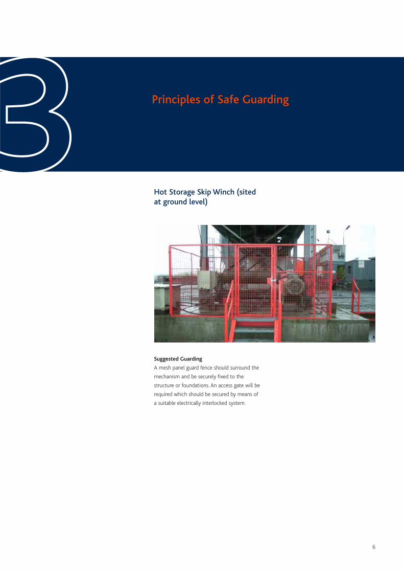
Hot Storage Skip Winch (sitedat ground level)
Principles of Safe Guarding33Suggested Guarding
A mesh panel guard fence should surround the
mechanism and be securely fixed to the
structure or foundations. An access gate will be
required which should be secured by means of
a suitable electrically interlocked system.
7
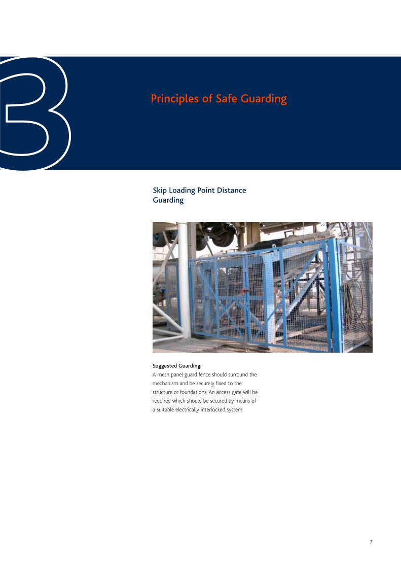
Skip Loading Point DistanceGuarding
Principles of Safe Guarding33Suggested Guarding
A mesh panel guard fence should surround the
mechanism and be securely fixed to the
structure or foundations. An access gate will be
required which should be secured by means of
a suitable electrically interlocked system.
8
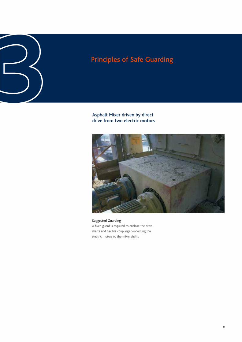
Asphalt Mixer driven by directdrive from two electric motors
Principles of Safe Guarding33Suggested Guarding
A fixed guard is required to enclose the drive
shafts and flexible couplings connecting the
electric motors to the mixer shafts.
9
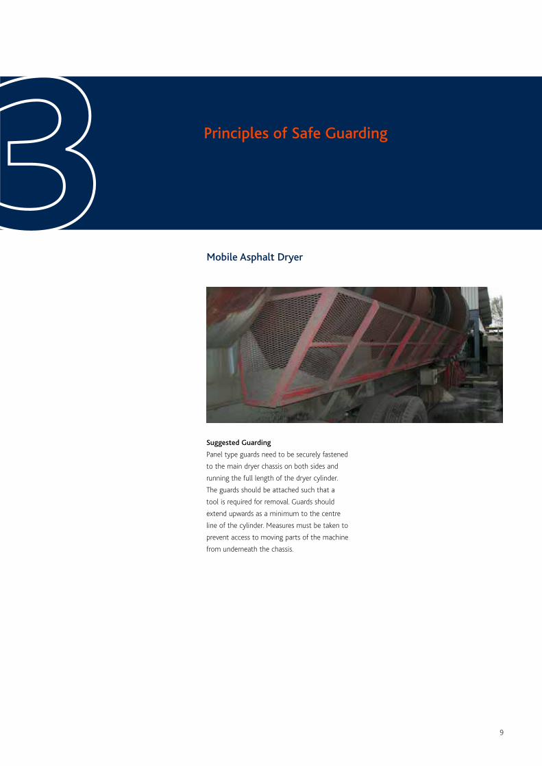
Mobile Asphalt Dryer
Principles of Safe Guarding33Suggested Guarding
Panel type guards need to be securely fastened
to the main dryer chassis on both sides and
running the full length of the dryer cylinder.
The guards should be attached such that a
tool is required for removal. Guards should
extend upwards as a minimum to the centre
line of the cylinder. Measures must be taken to
prevent access to moving parts of the machine
from underneath the chassis.
10
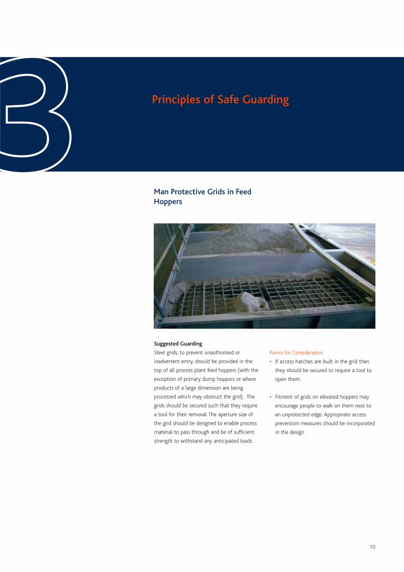
Man Protective Grids in FeedHoppers
Principles of Safe Guarding33Suggested Guarding
Steel grids, to prevent unauthorised or
inadvertent entry, should be provided in the
top of all process plant feed hoppers (with the
exception of primary dump hoppers or where
products of a large dimension are being
processed which may obstruct the grid). The
grids should be secured such that they require
a tool for their removal. The aperture size of
the grid should be designed to enable process
material to pass through and be of sufficient
strength to withstand any anticipated loads.
Points for Consideration
• If access hatches are built in the grid then
they should be secured to require a tool to
open them.
• Fitment of grids on elevated hoppers may
encourage people to walk on them next to
an unprotected edge. Appropriate access
prevention measures should be incorporated
in the design
11
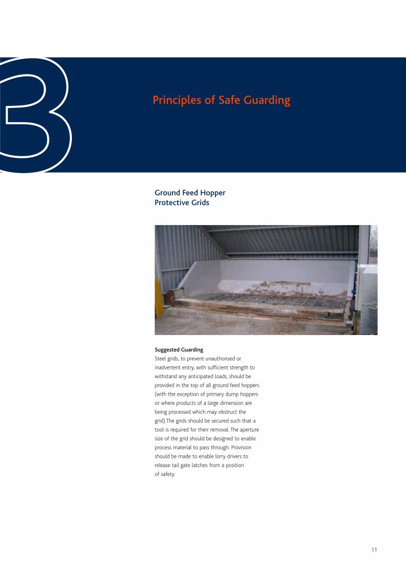
Ground Feed HopperProtective Grids
Principles of Safe Guarding33Suggested Guarding
Steel grids, to prevent unauthorised or
inadvertent entry, with sufficient strength to
withstand any anticipated loads, should be
provided in the top of all ground feed hoppers
(with the exception of primary dump hoppers
or where products of a large dimension are
being processed which may obstruct the
grid).The grids should be secured such that a
tool is required for their removal. The aperture
size of the grid should be designed to enable
process material to pass through. Provision
should be made to enable lorry drivers to
release tail gate latches from a position
of safety.
12
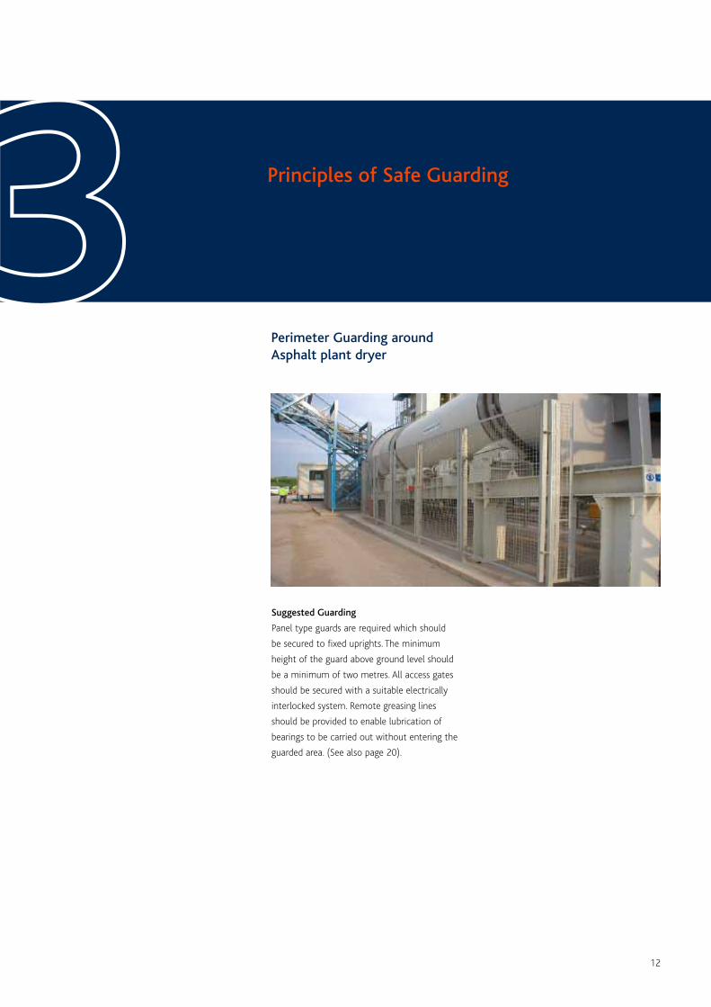
Perimeter Guarding aroundAsphalt plant dryer
Principles of Safe Guarding33Suggested Guarding
Panel type guards are required which should
be secured to fixed uprights. The minimum
height of the guard above ground level should
be a minimum of two metres. All access gates
should be secured with a suitable electrically
interlocked system. Remote greasing lines
should be provided to enable lubrication of
bearings to be carried out without entering the
guarded area. (See also page 20).
13
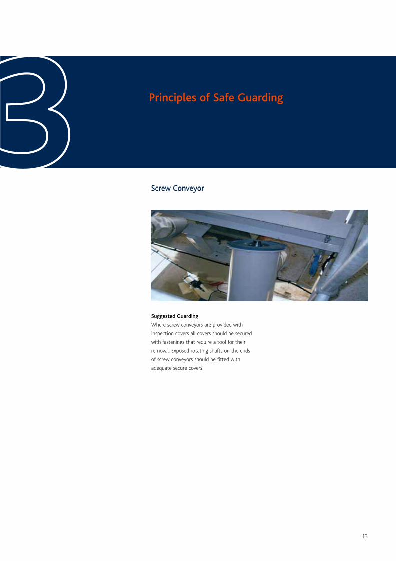
Screw Conveyor
Principles of Safe Guarding33Suggested Guarding
Where screw conveyors are provided with
inspection covers all covers should be secured
with fastenings that require a tool for their
removal. Exposed rotating shafts on the ends
of screw conveyors should be fitted with
adequate secure covers.
14
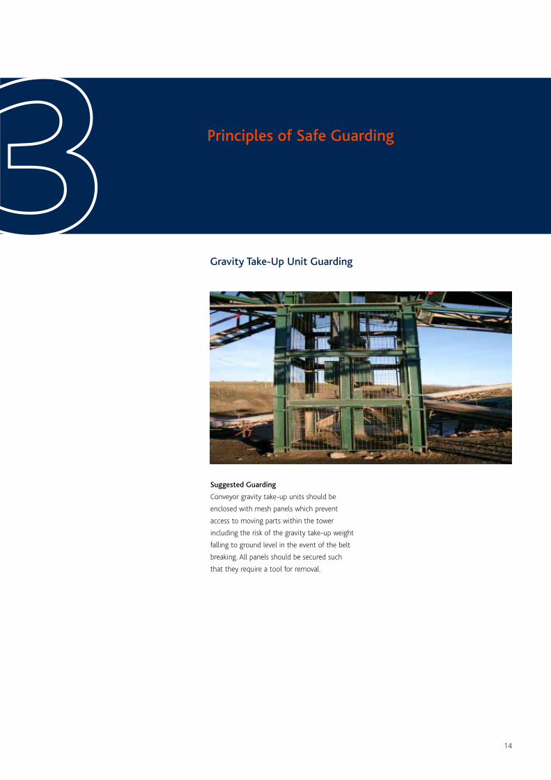
Gravity Take-Up Unit Guarding
Principles of Safe Guarding33Suggested Guarding
Conveyor gravity take-up units should be
enclosed with mesh panels which prevent
access to moving parts within the tower
including the risk of the gravity take-up weight
falling to ground level in the event of the belt
breaking. All panels should be secured such
that they require a tool for removal.
15
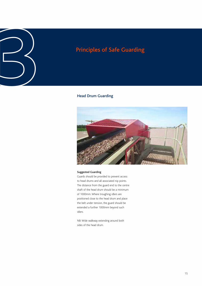
Head Drum Guarding
Principles of Safe Guarding33Suggested Guarding
Guards should be provided to prevent access
to head drums and all associated nip points.
The distance from the guard end to the centre
shaft of the head drum should be a minimum
of 1000mm. Where troughing idlers are
positioned close to the head drum and place
the belt under tension, the guard should be
extended a further 1000mm beyond such
idlers.
NB: Wide walkway extending around both
sides of the head drum.
16
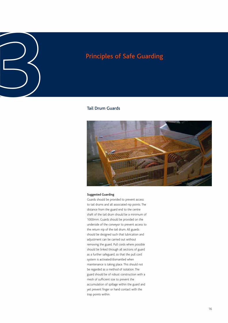
Tail Drum Guards
Principles of Safe Guarding33Suggested Guarding
Guards should be provided to prevent access
to tail drums and all associated nip points. The
distance from the guard end to the centre
shaft of the tail drum should be a minimum of
1000mm. Guards should be provided on the
underside of the conveyor to prevent access to
the return nip of the tail drum. All guards
should be designed such that lubrication and
adjustment can be carried out without
removing the guard. Pull cords where possible
should be linked through all sections of guard
as a further safeguard, so that the pull cord
system is activated/dismantled when
maintenance is taking place. This should not
be regarded as a method of isolation. The
guard should be of robust construction with a
mesh of sufficient size to prevent the
accumulation of spillage within the guard and
yet prevent finger or hand contact with the
trap points within.
17
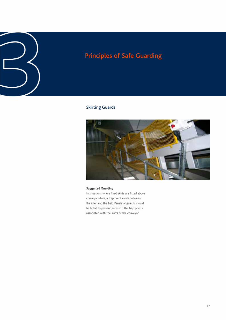
Skirting Guards
Principles of Safe Guarding33Suggested Guarding
In situations where fixed skirts are fitted above
conveyor idlers, a trap point exists between
the idler and the belt. Panels of guards should
be fitted to prevent access to the trap points
associated with the skirts of the conveyor.
18
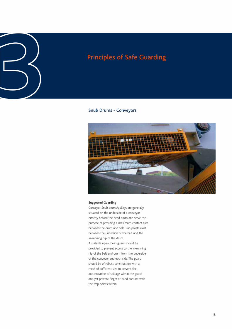
Snub Drums - Conveyors
Principles of Safe Guarding33Suggested Guarding
Conveyor Snub drums/pulleys are generally
situated on the underside of a conveyor
directly behind the head drum and serve the
purpose of providing a maximum contact area
between the drum and belt. Trap points exist
between the underside of the belt and the
in-running nip of the drum.
A suitable open mesh guard should be
provided to prevent access to the in-running
nip of the belt and drum from the underside
of the conveyor and each side. The guard
should be of robust construction with a
mesh of sufficient size to prevent the
accumulation of spillage within the guard
and yet prevent finger or hand contact with
the trap points within.
19
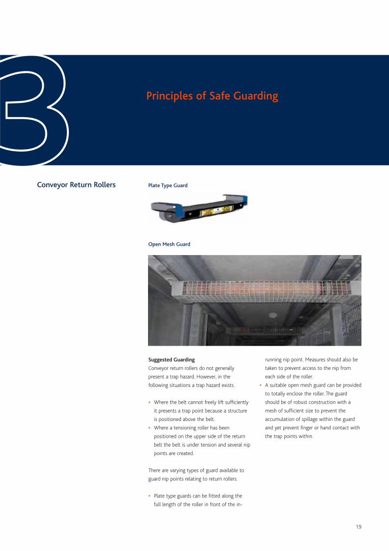
Conveyor Return Rollers
Principles of Safe Guarding33Suggested Guarding
Conveyor return rollers do not generally
present a trap hazard. However, in the
following situations a trap hazard exists.
• Where the belt cannot freely lift sufficiently
it presents a trap point because a structure
is positioned above the belt.
• Where a tensioning roller has been
positioned on the upper side of the return
belt the belt is under tension and several nip
points are created.
There are varying types of guard available to
guard nip points relating to return rollers.
• Plate type guards can be fitted along the
full length of the roller in front of the in-
Plate Type Guard
Open Mesh Guard
running nip point. Measures should also be
taken to prevent access to the nip from
each side of the roller.
• A suitable open mesh guard can be provided
to totally enclose the roller. The guard
should be of robust construction with a
mesh of sufficient size to prevent the
accumulation of spillage within the guard
and yet prevent finger or hand contact with
the trap points within.
20
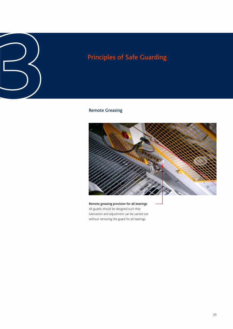
Remote Greasing
Principles of Safe Guarding33Remote greasing provision for all bearings
All guards should be designed such that
lubrication and adjustment can be carried out
without removing the guard for all bearings.
21
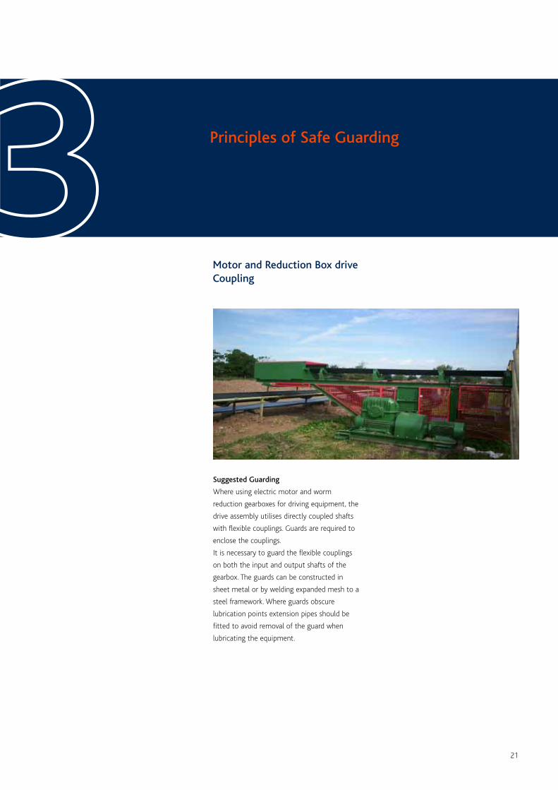
Motor and Reduction Box driveCoupling
Principles of Safe Guarding33Suggested Guarding
Where using electric motor and worm
reduction gearboxes for driving equipment, the
drive assembly utilises directly coupled shafts
with flexible couplings. Guards are required to
enclose the couplings.
It is necessary to guard the flexible couplings
on both the input and output shafts of the
gearbox. The guards can be constructed in
sheet metal or by welding expanded mesh to a
steel framework. Where guards obscure
lubrication points extension pipes should be
fitted to avoid removal of the guard when
lubricating the equipment.
22
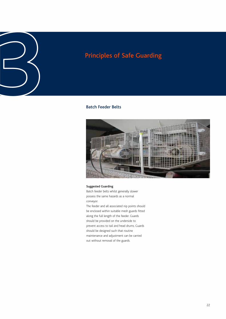
Batch Feeder Belts
Principles of Safe Guarding33Suggested Guarding
Batch feeder belts whilst generally slower
possess the same hazards as a normal
conveyor.
The feeder and all associated nip points should
be enclosed within suitable mesh guards fitted
along the full length of the feeder. Guards
should be provided on the underside to
prevent access to tail and head drums. Guards
should be designed such that routine
maintenance and adjustment can be carried
out without removal of the guards.
23
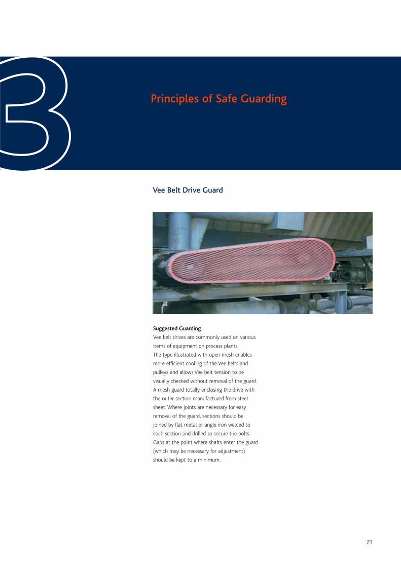
Vee Belt Drive Guard
Principles of Safe Guarding33Suggested Guarding
Vee belt drives are commonly used on various
items of equipment on process plants.
The type illustrated with open mesh enables
more efficient cooling of the Vee belts and
pulleys and allows Vee belt tension to be
visually checked without removal of the guard.
A mesh guard totally enclosing the drive with
the outer section manufactured from steel
sheet. Where joints are necessary for easy
removal of the guard, sections should be
joined by flat metal or angle iron welded to
each section and drilled to secure the bolts.
Gaps at the point where shafts enter the guard
(which may be necessary for adjustment)
should be kept to a minimum.
24
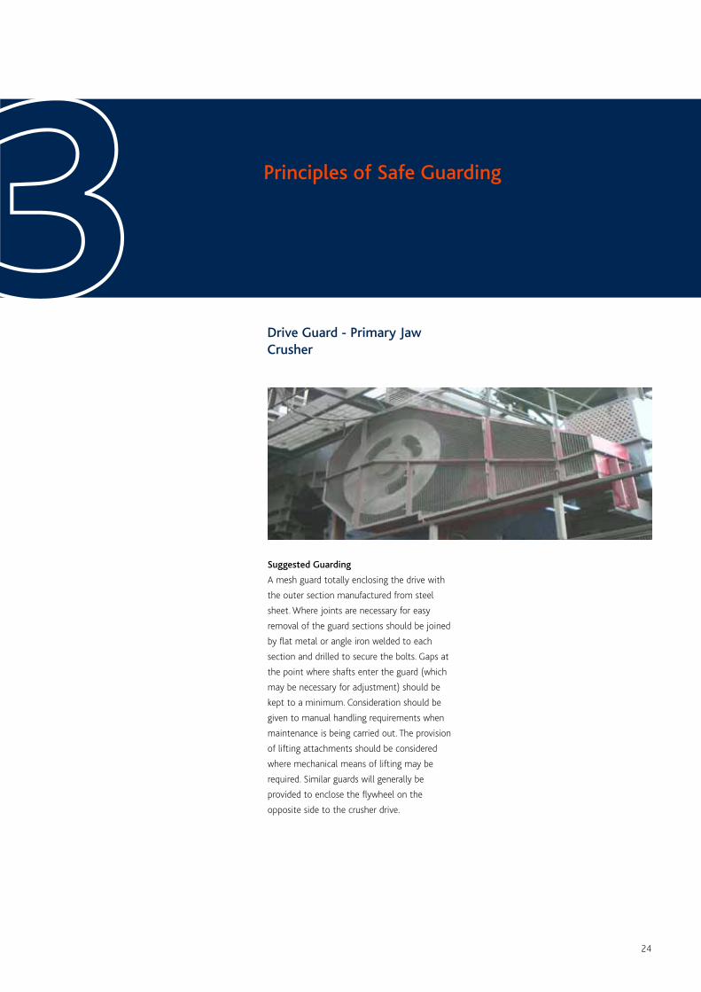
Drive Guard - Primary JawCrusher
Principles of Safe Guarding33Suggested Guarding
A mesh guard totally enclosing the drive with
the outer section manufactured from steel
sheet. Where joints are necessary for easy
removal of the guard sections should be joined
by flat metal or angle iron welded to each
section and drilled to secure the bolts. Gaps at
the point where shafts enter the guard (which
may be necessary for adjustment) should be
kept to a minimum. Consideration should be
given to manual handling requirements when
maintenance is being carried out. The provision
of lifting attachments should be considered
where mechanical means of lifting may be
required. Similar guards will generally be
provided to enclose the flywheel on the
opposite side to the crusher drive.
25
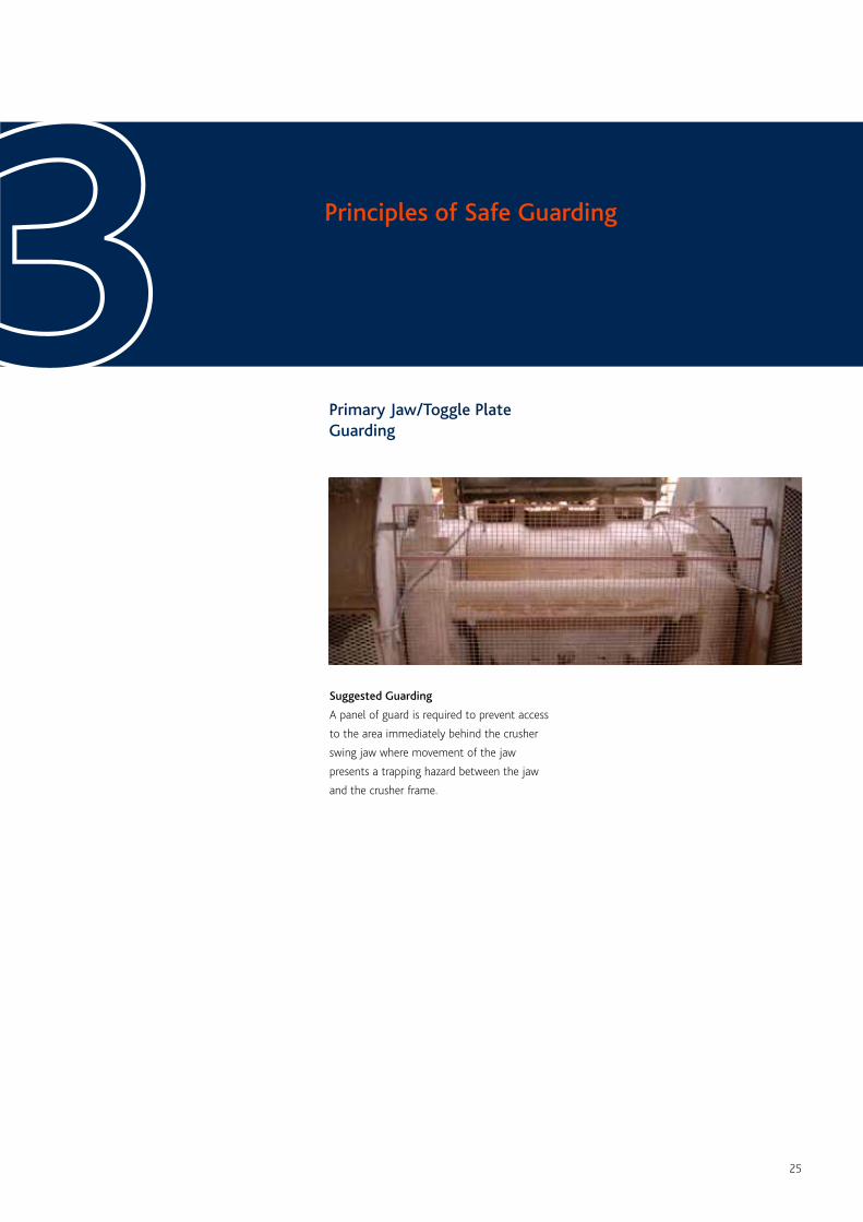
Primary Jaw/Toggle PlateGuarding
Principles of Safe Guarding33Suggested Guarding
A panel of guard is required to prevent access
to the area immediately behind the crusher
swing jaw where movement of the jaw
presents a trapping hazard between the jaw
and the crusher frame.
26
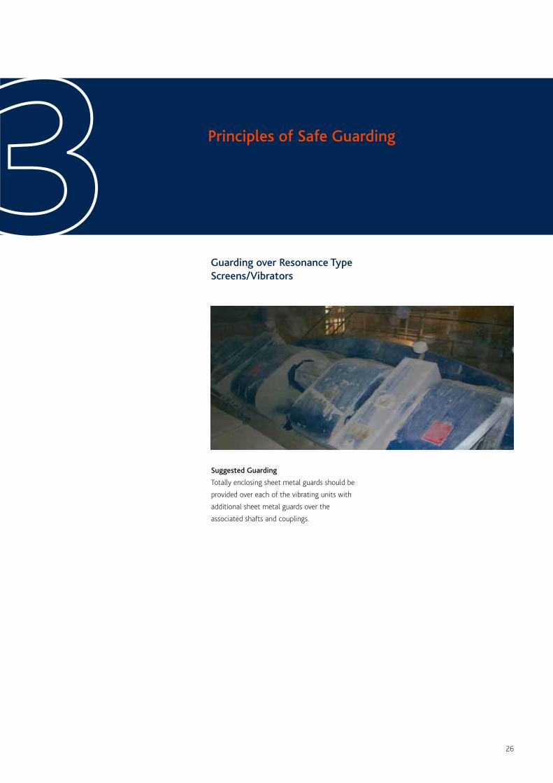
Guarding over Resonance TypeScreens/Vibrators
Principles of Safe Guarding33Suggested Guarding
Totally enclosing sheet metal guards should be
provided over each of the vibrating units with
additional sheet metal guards over the
associated shafts and couplings.
27
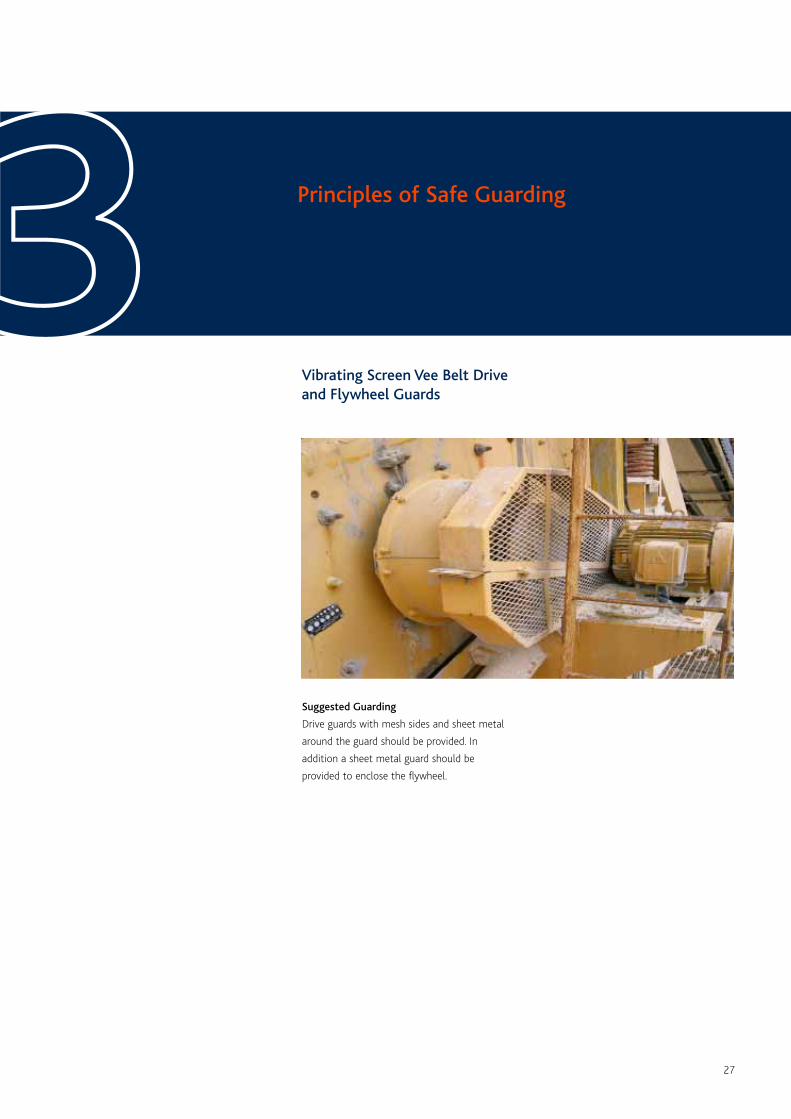
Vibrating Screen Vee Belt Driveand Flywheel Guards
Principles of Safe Guarding33Suggested Guarding
Drive guards with mesh sides and sheet metal
around the guard should be provided. In
addition a sheet metal guard should be
provided to enclose the flywheel.
28
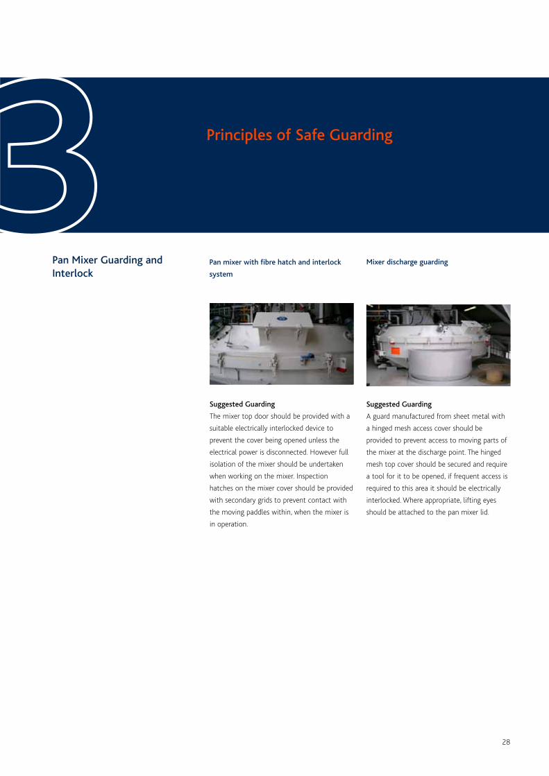
Pan Mixer Guarding andInterlock
Principles of Safe Guarding33Suggested Guarding
The mixer top door should be provided with a
suitable electrically interlocked device to
prevent the cover being opened unless the
electrical power is disconnected. However full
isolation of the mixer should be undertaken
when working on the mixer. Inspection
hatches on the mixer cover should be provided
with secondary grids to prevent contact with
the moving paddles within, when the mixer is
in operation.
Suggested Guarding
A guard manufactured from sheet metal with
a hinged mesh access cover should be
provided to prevent access to moving parts of
the mixer at the discharge point. The hinged
mesh top cover should be secured and require
a tool for it to be opened, if frequent access is
required to this area it should be electrically
interlocked. Where appropriate, lifting eyes
should be attached to the pan mixer lid.
Pan mixer with fibre hatch and interlock
system
Mixer discharge guarding
29
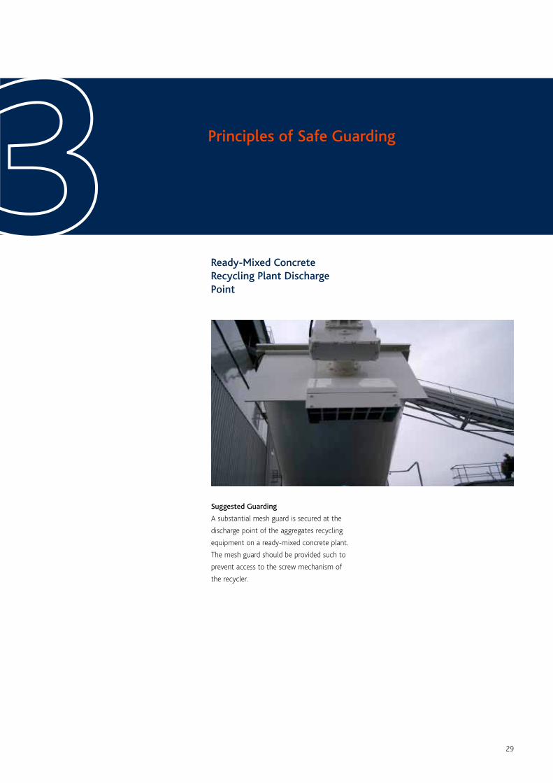
Ready-Mixed ConcreteRecycling Plant DischargePoint
Principles of Safe Guarding33Suggested Guarding
A substantial mesh guard is secured at the
discharge point of the aggregates recycling
equipment on a ready-mixed concrete plant.
The mesh guard should be provided such to
prevent access to the screw mechanism of
the recycler.
30
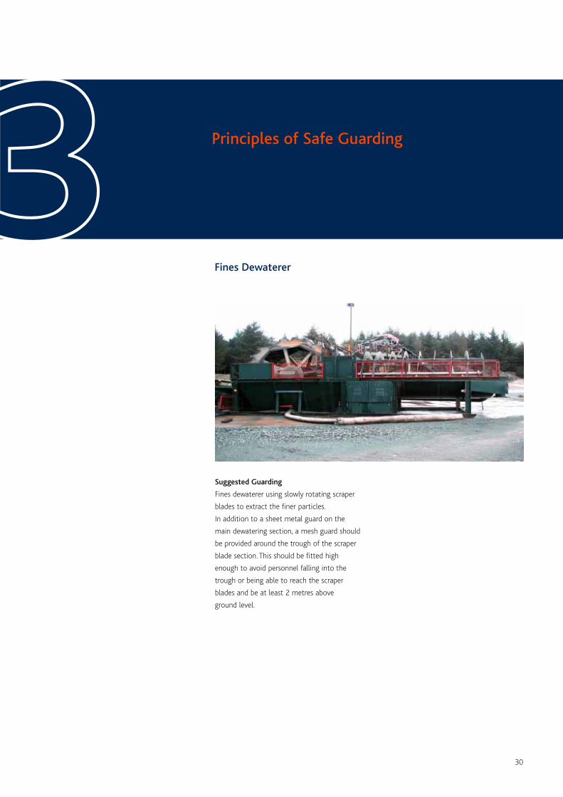
Fines Dewaterer
Principles of Safe Guarding33Suggested Guarding
Fines dewaterer using slowly rotating scraper
blades to extract the finer particles.
In addition to a sheet metal guard on the
main dewatering section, a mesh guard should
be provided around the trough of the scraper
blade section. This should be fitted high
enough to avoid personnel falling into the
trough or being able to reach the scraper
blades and be at least 2 metres above
ground level.
31
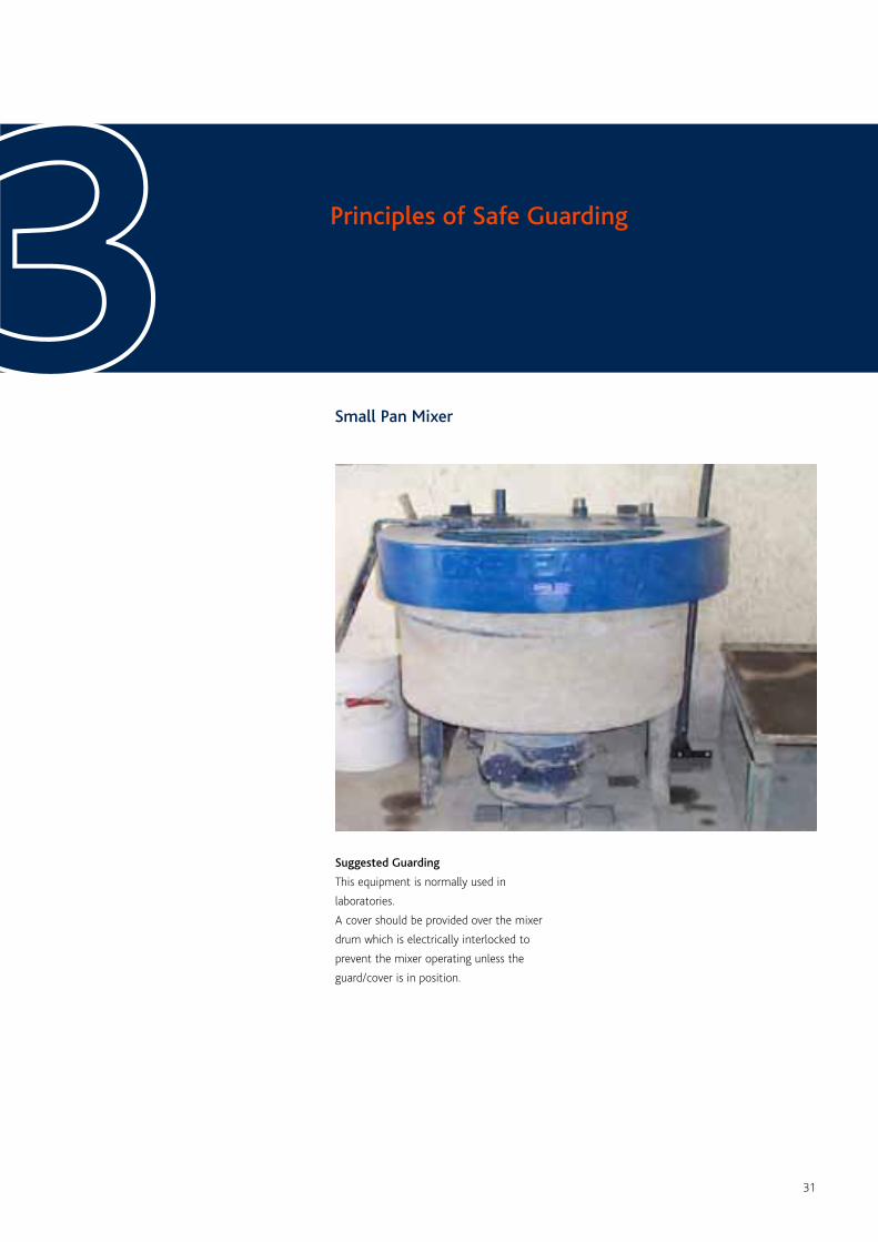
Small Pan Mixer
Principles of Safe Guarding33Suggested Guarding
This equipment is normally used in
laboratories.
A cover should be provided over the mixer
drum which is electrically interlocked to
prevent the mixer operating unless the
guard/cover is in position.
32
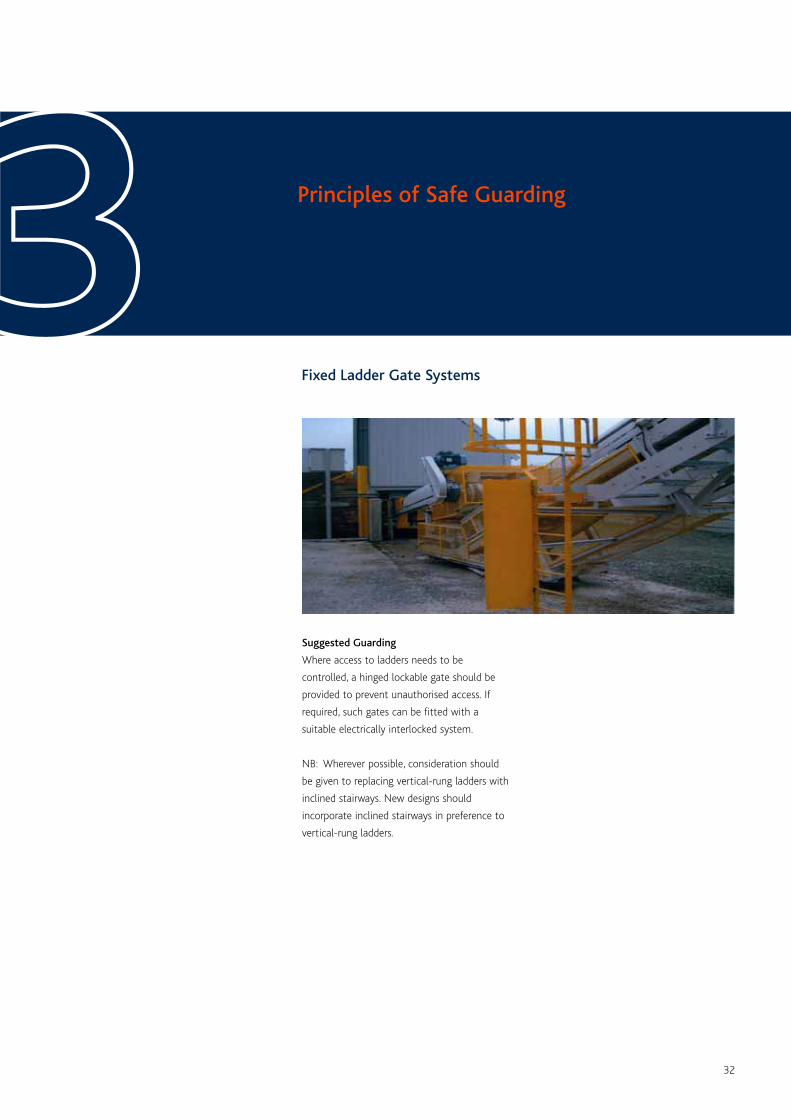
Fixed Ladder Gate Systems
Principles of Safe Guarding33Suggested Guarding
Where access to ladders needs to be
controlled, a hinged lockable gate should be
provided to prevent unauthorised access. If
required, such gates can be fitted with a
suitable electrically interlocked system.
NB: Wherever possible, consideration should
be given to replacing vertical-rung ladders with
inclined stairways. New designs should
incorporate inclined stairways in preference to
vertical-rung ladders.
33
Fixed Ladders
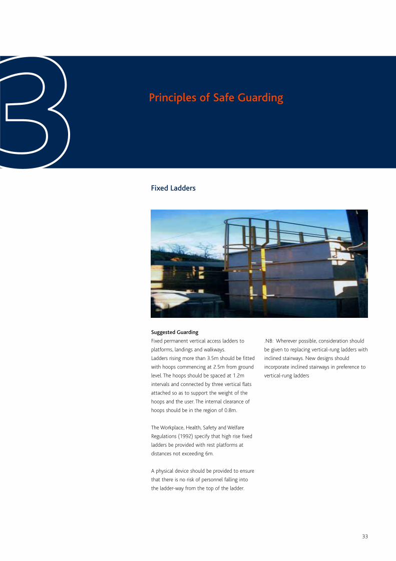
Principles of Safe Guarding33Suggested Guarding
Fixed permanent vertical access ladders to
platforms, landings and walkways.
Ladders rising more than 3.5m should be fitted
with hoops commencing at 2.5m from ground
level. The hoops should be spaced at 1.2m
intervals and connected by three vertical flats
attached so as to support the weight of the
hoops and the user. The internal clearance of
hoops should be in the region of 0.8m.
The Workplace, Health, Safety and Welfare
Regulations (1992) specify that high rise fixed
ladders be provided with rest platforms at
distances not exceeding 6m.
A physical device should be provided to ensure
that there is no risk of personnel falling into
the ladder-way from the top of the ladder.
.NB: Wherever possible, consideration should
be given to replacing vertical-rung ladders with
inclined stairways. New designs should
incorporate inclined stairways in preference to
vertical-rung ladders
34
Robot Guarding
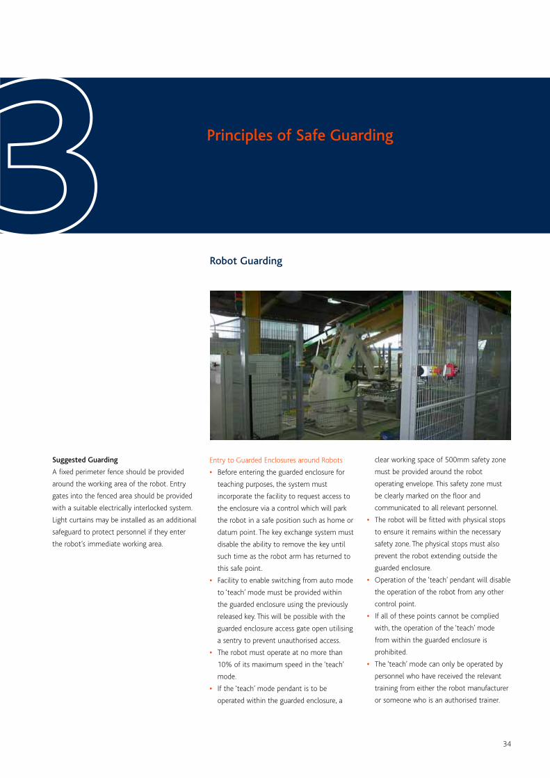
Principles of Safe Guarding33Suggested Guarding
A fixed perimeter fence should be provided
around the working area of the robot. Entry
gates into the fenced area should be provided
with a suitable electrically interlocked system.
Light curtains may be installed as an additional
safeguard to protect personnel if they enter
the robot’s immediate working area.
Entry to Guarded Enclosures around Robots
• Before entering the guarded enclosure for
teaching purposes, the system must
incorporate the facility to request access to
the enclosure via a control which will park
the robot in a safe position such as home or
datum point. The key exchange system must
disable the ability to remove the key until
such time as the robot arm has returned to
this safe point.
• Facility to enable switching from auto mode
to ‘teach’ mode must be provided within
the guarded enclosure using the previously
released key. This will be possible with the
guarded enclosure access gate open utilising
a sentry to prevent unauthorised access.
• The robot must operate at no more than
10% of its maximum speed in the ‘teach’
mode.
• If the ‘teach’ mode pendant is to be
operated within the guarded enclosure, a
clear working space of 500mm safety zone
must be provided around the robot
operating envelope. This safety zone must
be clearly marked on the floor and
communicated to all relevant personnel.
• The robot will be fitted with physical stops
to ensure it remains within the necessary
safety zone. The physical stops must also
prevent the robot extending outside the
guarded enclosure.
• Operation of the ‘teach’ pendant will disable
the operation of the robot from any other
control point.
• If all of these points cannot be complied
with, the operation of the ‘teach’ mode
from within the guarded enclosure is
prohibited.
• The ‘teach’ mode can only be operated by
personnel who have received the relevant
training from either the robot manufacturer
or someone who is an authorised trainer.
35
Vehicular Mobile Plant
Principles of Safe Guarding33Measures should be taken to guard the
following areas of vehicular mobile plant.
• Engine cooling fans and their associated
drive belts and pulleys.
• Any ancillary drive belts and pulleys which
are accessible when engine covers are open.
• Injector pump drive couplings in certain
equipment.
• Power take off shafts on agricultural type
tractors.
• Ancillary prop shafts.

36
Appendix 1
The Supply of Machinery (Safety) Regulations 1992 – ISBN 0 11 0257 19 7
Safe Use of Work Equipment (Provision and Use of Work Equipment Regulations 1998)
Approved Code of Practice – ISBN 0 7176 1626 6
British Standard BS7300: 1990 Code of Practice for Safeguarding of the hazard points on
troughed belt conveyors – ISBN 0 580 18346 7
NB: At time of going to Press, this standard has been proposed for withdrawal and will be
superseded by BS EN 618 and 620
Public Document – Safe Use of Machinery PD5304: 2000 – ISBN 0 580 33207 1
BS EN ISO 12100-1: 2003 (replaced BS EN 292-1: 1991): Safety of Machinery – Basic
concepts and general principles for design – Part 1: Basic terminology and methodology.
BS EN ISO 12100-2: 2003 (replaced BS EN 292-2: 1991, as amended in 1995 and 1997):
Safety of Machinery – Basic concepts and general principles for design – Part 2: Technical
principles and specifications.
BS EN 294: 1992, Safety of Machinery – Safety distances to prevent danger zones being
reached by the upper limbs. Amended by AMD 7655 of 15 March 1993
BS EN 349: 1993, Safety of Machinery – Minimum gaps to avoid crushing of parts of the
human body.

Providing EssentialMaterials for Britain
Gillingham House
38 - 44 Gillingham Street
London SW1V 1HU
Tel 020 7963 8000
Fax 020 7963 8001
www.qpa.org
The trade association forthe aggregate, asphaltand ready-mixed concreteindustries