Embed Size (px)
Citation preview
Guaranteed Power Supply In Computer CentresUsing Modular UPS Plants
White Paper 01
White Paper: Guaranteed Power Supply In Computer Centres Using Modular UPS plants
2
Table of Contents
1 Why are UPS plants so important? ___________________________________ 32 UPS plant components ____________________________________________ 6
2.1 The rectifier __________________________________________________ 62.2 The direct current link circuit _____________________________________ 62.3 The energy storage ____________________________________________ 62.4 The inverter __________________________________________________ 72.5 The static bypass ______________________________________________ 7
3 The UPS operating modes _________________________________________ 73.1 Normal operation ______________________________________________ 73.2 Battery operation ______________________________________________ 73.3 Bypass operation ______________________________________________ 7
4 Network faults in the public power supply mains_________________________ 85 The various UPS types and their classification in accordance with the product
standard EN 62040-3______________________________________________ 95.1 Level 1 of the classification code: The dependency of the UPS output on the
mains _______________________________________________________ 95.2 Level 2 of the classification code: The voltage curve form of the UPS output
115.3 Level 3 of the classification code: The dynamic tolerance curves of the output
125.4 Which UPS plants protect against which mains faults? ________________ 135.5 Assignment of the old designations for UPS plants to the classification as
specified by EN 62040-3 _______________________________________ 146 The battery as energy storage______________________________________ 147 Transformer-less UPS plants_______________________________________ 158 Redundancy of the UPS plant ______________________________________ 179 Modular UPS plants______________________________________________ 1710 Calculation of the availability _______________________________________ 1811 Architecture of modular UPS plants__________________________________ 2012 Dimensioning of UPS plants _______________________________________ 2213 Effect of the efficiency on the running costs ___________________________ 2414 Management of the UPS plant______________________________________ 2615 Service and maintenance of the UPS plant____________________________ 2716 Summary ______________________________________________________ 29
White Paper: Guaranteed Power Supply In Computer Centres Using Modular UPS plants
3
1 Why are UPS plants so important?
Nowadays, uninterruptible power supplies belong to the most important securitycomponents in operational equipment. Almost nothing operates without power. Everymanufacturing process comes to a standstill without power and also hardly anyadministration can continue to work without power and thus without PCs.
In addition to these stoppage problems, power failures in computer centres haveadditional consequences. Important data can be damaged or lost. Even moredevastating is the interruption of the power supply in hospitals, because here humanlife and limb are endangered.
These examples show how important a reliable power supply is and whichconsequences a power supply failure has. We are, however, normally not aware ofour dependency on a functioning power supply. This is because of the very highsupply quality in Central Europe.
Figure 1.1 shows the power failures in some European countries in 1999. This showsthat every German in 1999 was without power for 15 minutes on average. The powersupply in the Netherlands, with 25 minutes of power failure per year, was at a similarhigh level as in Germany. France and Great Britain, each with approximately 1 hourof power failures per year follow. The power supply in Norway and Italy issignificantly more unstable. The citizens of Norway and Italy in 1999 wereapproximately 3 hours without power on average.
Figure 1.1 Power failures in Europe (source: Erlangen municipal services)
An uninterruptible power supply, in addition to bridging power failures, has theadditional positive property, namely, the improvement of the quality of the powersupply. For example, voltage dips, overvoltages, harmonics, ... are kept away fromconsumers attached to the UPS. Good UPS plants supply their consumers with anabsolutely stable frequency, even for frequency fluctuations on the public mainsnetwork.
White Paper: Guaranteed Power Supply In Computer Centres Using Modular UPS plants
4
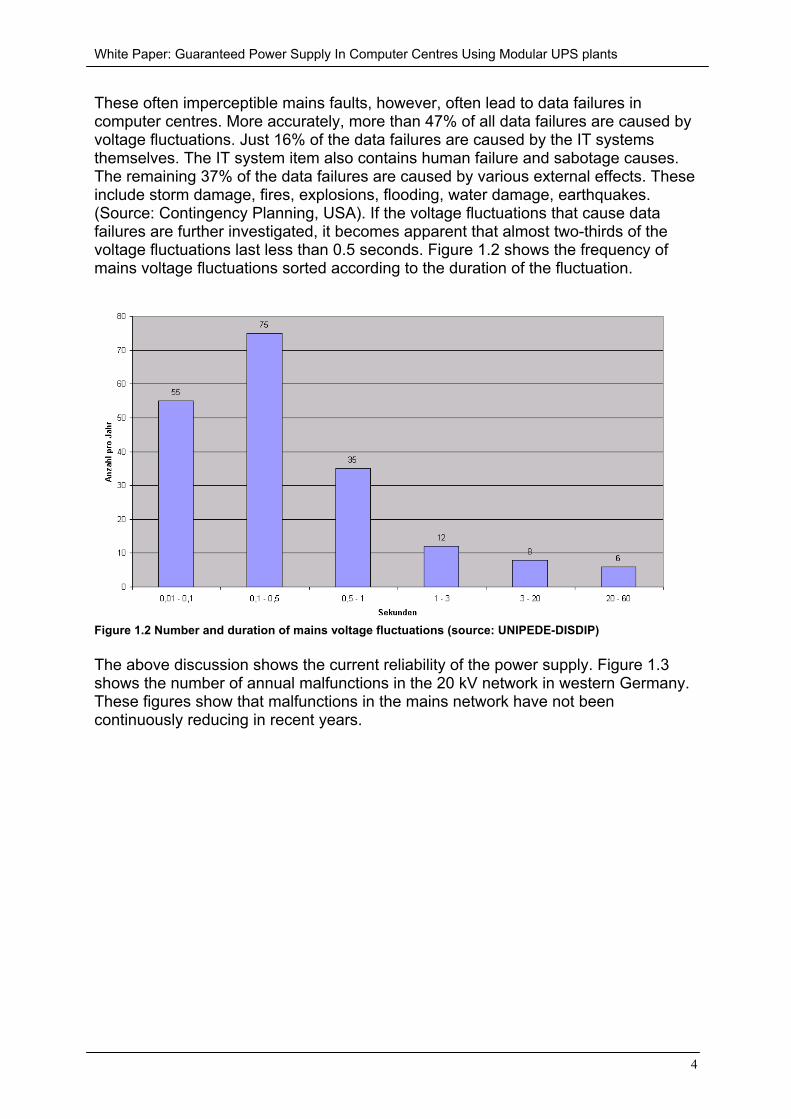
These often imperceptible mains faults, however, often lead to data failures incomputer centres. More accurately, more than 47% of all data failures are caused byvoltage fluctuations. Just 16% of the data failures are caused by the IT systemsthemselves. The IT system item also contains human failure and sabotage causes.The remaining 37% of the data failures are caused by various external effects. Theseinclude storm damage, fires, explosions, flooding, water damage, earthquakes.(Source: Contingency Planning, USA). If the voltage fluctuations that cause datafailures are further investigated, it becomes apparent that almost two-thirds of thevoltage fluctuations last less than 0.5 seconds. Figure 1.2 shows the frequency ofmains voltage fluctuations sorted according to the duration of the fluctuation.
Figure 1.2 Number and duration of mains voltage fluctuations (source: UNIPEDE-DISDIP)
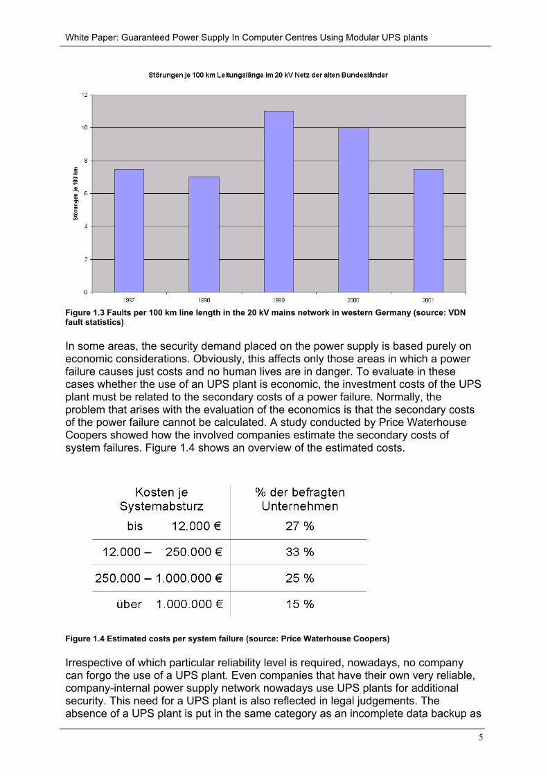
The above discussion shows the current reliability of the power supply. Figure 1.3shows the number of annual malfunctions in the 20 kV network in western Germany.These figures show that malfunctions in the mains network have not beencontinuously reducing in recent years.
White Paper: Guaranteed Power Supply In Computer Centres Using Modular UPS plants
5
Figure 1.3 Faults per 100 km line length in the 20 kV mains network in western Germany (source: VDNfault statistics)
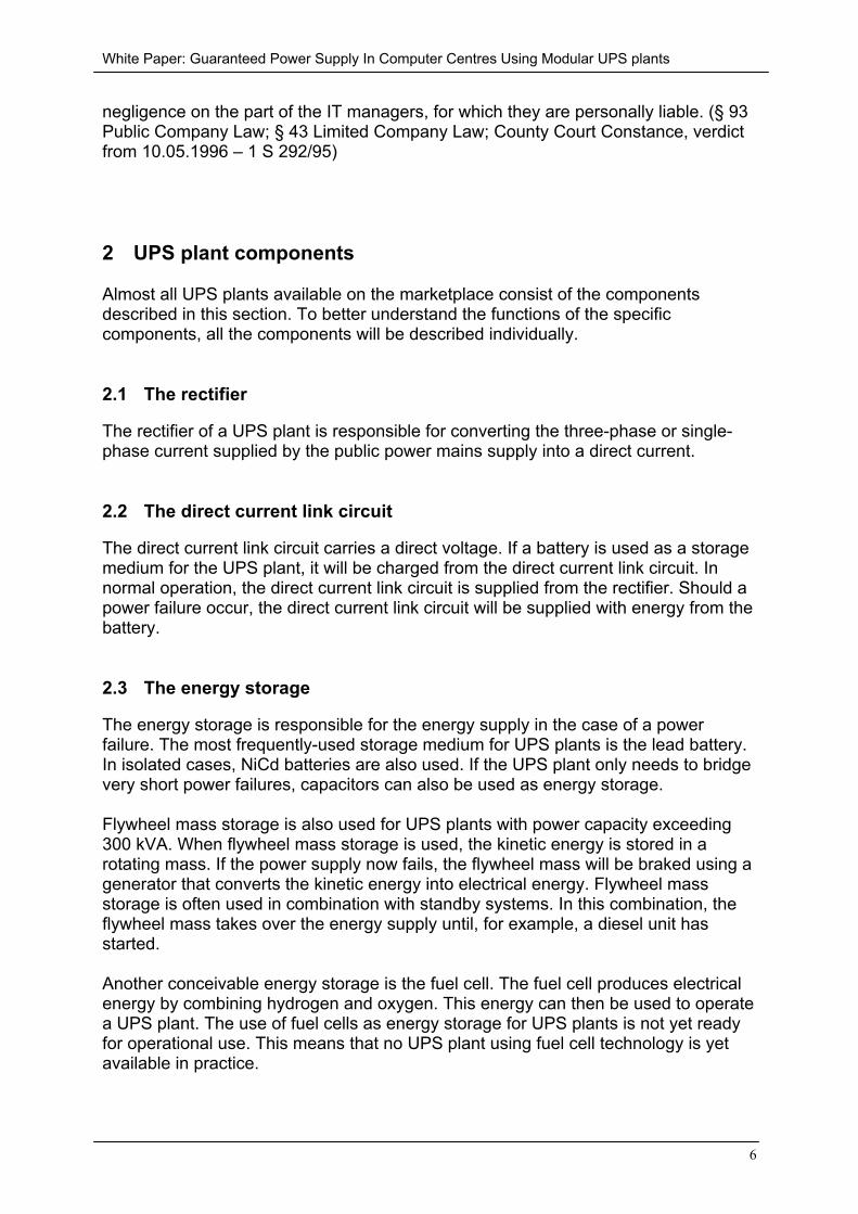
In some areas, the security demand placed on the power supply is based purely oneconomic considerations. Obviously, this affects only those areas in which a powerfailure causes just costs and no human lives are in danger. To evaluate in thesecases whether the use of an UPS plant is economic, the investment costs of the UPSplant must be related to the secondary costs of a power failure. Normally, theproblem that arises with the evaluation of the economics is that the secondary costsof the power failure cannot be calculated. A study conducted by Price WaterhouseCoopers showed how the involved companies estimate the secondary costs ofsystem failures. Figure 1.4 shows an overview of the estimated costs.
Figure 1.4 Estimated costs per system failure (source: Price Waterhouse Coopers)
Irrespective of which particular reliability level is required, nowadays, no companycan forgo the use of a UPS plant. Even companies that have their own very reliable,company-internal power supply network nowadays use UPS plants for additionalsecurity. This need for a UPS plant is also reflected in legal judgements. Theabsence of a UPS plant is put in the same category as an incomplete data backup as
White Paper: Guaranteed Power Supply In Computer Centres Using Modular UPS plants
6
negligence on the part of the IT managers, for which they are personally liable. (§ 93Public Company Law; § 43 Limited Company Law; County Court Constance, verdictfrom 10.05.1996 – 1 S 292/95)
2 UPS plant components
Almost all UPS plants available on the marketplace consist of the componentsdescribed in this section. To better understand the functions of the specificcomponents, all the components will be described individually.
2.1 The rectifier
The rectifier of a UPS plant is responsible for converting the three-phase or single-phase current supplied by the public power mains supply into a direct current.
2.2 The direct current link circuit
The direct current link circuit carries a direct voltage. If a battery is used as a storagemedium for the UPS plant, it will be charged from the direct current link circuit. Innormal operation, the direct current link circuit is supplied from the rectifier. Should apower failure occur, the direct current link circuit will be supplied with energy from thebattery.
2.3 The energy storage
The energy storage is responsible for the energy supply in the case of a powerfailure. The most frequently-used storage medium for UPS plants is the lead battery.In isolated cases, NiCd batteries are also used. If the UPS plant only needs to bridgevery short power failures, capacitors can also be used as energy storage.
Flywheel mass storage is also used for UPS plants with power capacity exceeding300 kVA. When flywheel mass storage is used, the kinetic energy is stored in arotating mass. If the power supply now fails, the flywheel mass will be braked using agenerator that converts the kinetic energy into electrical energy. Flywheel massstorage is often used in combination with standby systems. In this combination, theflywheel mass takes over the energy supply until, for example, a diesel unit hasstarted.
Another conceivable energy storage is the fuel cell. The fuel cell produces electricalenergy by combining hydrogen and oxygen. This energy can then be used to operatea UPS plant. The use of fuel cells as energy storage for UPS plants is not yet readyfor operational use. This means that no UPS plant using fuel cell technology is yetavailable in practice.
White Paper: Guaranteed Power Supply In Computer Centres Using Modular UPS plants
7
2.4 The inverter
The inverter is responsible for converting the energy provided by the direct currentlink circuit into a sinusoidal alternating current with the amplitude and the frequencyof the mains voltage.
2.5 The static bypass
The so-called static bypass is described as last possibility. The static bypass is acurrent path from the public power supply mains network directly at the output of theUPS plant and thus to the critical load. If the static bypass is activated, the inverter isthen non-operational. The static bypass is switched on for an excessive loading ofthe inverter or for a defect of the inverter, rectifier or battery. Most UPS plants canalso be manually switched to the static bypass.
3 The UPS operating modes
For UPS plants, a differentiation is made between normal operation, batteryoperation and bypass operation.
3.1 Normal operation
As the name already says, the UPS usually runs in normal operation. In normaloperation, the rectifier is fed with energy from the public power supply mains and thebattery will be kept fully charged from the direct current link circuit.
3.2 Battery operation
If the power from the public power supply mains fails, the UPS switches to batteryoperation. In battery operation, the inverter will be fed with energy from the battery.The UPS plant continues to operate in battery operation until the energy of thebatteries becomes exhausted.
3.3 Bypass operation
The third operating mode is the bypass operation. In bypass operation, the criticalload is supplied directly via the bypass from the public power supply mains. The UPSswitches, for example, into bypass operation when too many consumers areconnected and so that the inverter is overloaded. Defects with the rectifier, inverter orbattery also cause switching to the bypass operation.
White Paper: Guaranteed Power Supply In Computer Centres Using Modular UPS plants
8
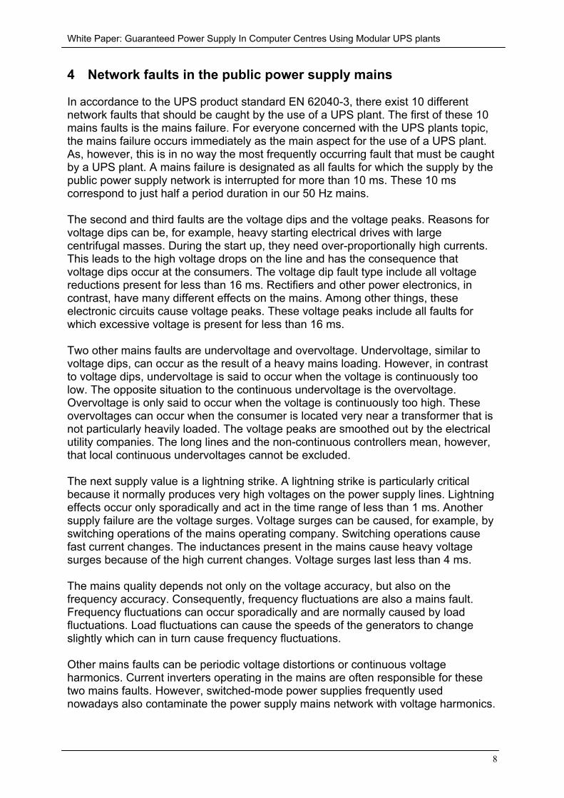
4 Network faults in the public power supply mains
In accordance to the UPS product standard EN 62040-3, there exist 10 differentnetwork faults that should be caught by the use of a UPS plant. The first of these 10mains faults is the mains failure. For everyone concerned with the UPS plants topic,the mains failure occurs immediately as the main aspect for the use of a UPS plant.As, however, this is in no way the most frequently occurring fault that must be caughtby a UPS plant. A mains failure is designated as all faults for which the supply by thepublic power supply network is interrupted for more than 10 ms. These 10 mscorrespond to just half a period duration in our 50 Hz mains.
The second and third faults are the voltage dips and the voltage peaks. Reasons forvoltage dips can be, for example, heavy starting electrical drives with largecentrifugal masses. During the start up, they need over-proportionally high currents.This leads to the high voltage drops on the line and has the consequence thatvoltage dips occur at the consumers. The voltage dip fault type include all voltagereductions present for less than 16 ms. Rectifiers and other power electronics, incontrast, have many different effects on the mains. Among other things, theseelectronic circuits cause voltage peaks. These voltage peaks include all faults forwhich excessive voltage is present for less than 16 ms.
Two other mains faults are undervoltage and overvoltage. Undervoltage, similar tovoltage dips, can occur as the result of a heavy mains loading. However, in contrastto voltage dips, undervoltage is said to occur when the voltage is continuously toolow. The opposite situation to the continuous undervoltage is the overvoltage.Overvoltage is only said to occur when the voltage is continuously too high. Theseovervoltages can occur when the consumer is located very near a transformer that isnot particularly heavily loaded. The voltage peaks are smoothed out by the electricalutility companies. The long lines and the non-continuous controllers mean, however,that local continuous undervoltages cannot be excluded.
The next supply value is a lightning strike. A lightning strike is particularly criticalbecause it normally produces very high voltages on the power supply lines. Lightningeffects occur only sporadically and act in the time range of less than 1 ms. Anothersupply failure are the voltage surges. Voltage surges can be caused, for example, byswitching operations of the mains operating company. Switching operations causefast current changes. The inductances present in the mains cause heavy voltagesurges because of the high current changes. Voltage surges last less than 4 ms.
The mains quality depends not only on the voltage accuracy, but also on thefrequency accuracy. Consequently, frequency fluctuations are also a mains fault.Frequency fluctuations can occur sporadically and are normally caused by loadfluctuations. Load fluctuations can cause the speeds of the generators to changeslightly which can in turn cause frequency fluctuations.
Other mains faults can be periodic voltage distortions or continuous voltageharmonics. Current inverters operating in the mains are often responsible for thesetwo mains faults. However, switched-mode power supplies frequently usednowadays also contaminate the power supply mains network with voltage harmonics.
White Paper: Guaranteed Power Supply In Computer Centres Using Modular UPS plants
9
5 The various UPS types and their classification in accordancewith the product standard EN 62040-3
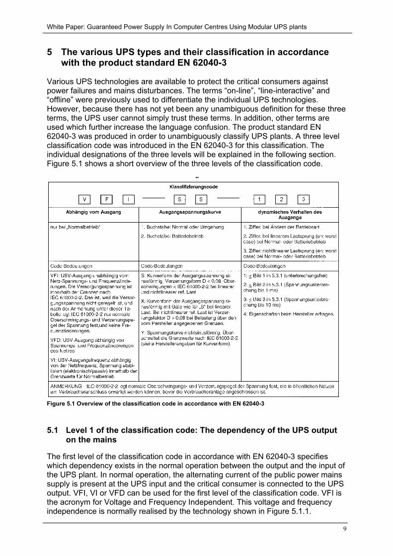
Various UPS technologies are available to protect the critical consumers againstpower failures and mains disturbances. The terms “on-line”, “line-interactive” and“offline” were previously used to differentiate the individual UPS technologies.However, because there has not yet been any unambiguous definition for these threeterms, the UPS user cannot simply trust these terms. In addition, other terms areused which further increase the language confusion. The product standard EN62040-3 was produced in order to unambiguously classify UPS plants. A three levelclassification code was introduced in the EN 62040-3 for this classification. Theindividual designations of the three levels will be explained in the following section.Figure 5.1 shows a short overview of the three levels of the classification code.
Figure 5.1 Overview of the classification code in accordance with EN 62040-3
5.1 Level 1 of the classification code: The dependency of the UPS outputon the mains
The first level of the classification code in accordance with EN 62040-3 specifieswhich dependency exists in the normal operation between the output and the input ofthe UPS plant. In normal operation, the alternating current of the public power mainssupply is present at the UPS input and the critical consumer is connected to the UPSoutput. VFI, VI or VFD can be used for the first level of the classification code. VFI isthe acronym for Voltage and Frequency Independent. This voltage and frequencyindependence is normally realised by the technology shown in Figure 5.1.1.
White Paper: Guaranteed Power Supply In Computer Centres Using Modular UPS plants
10
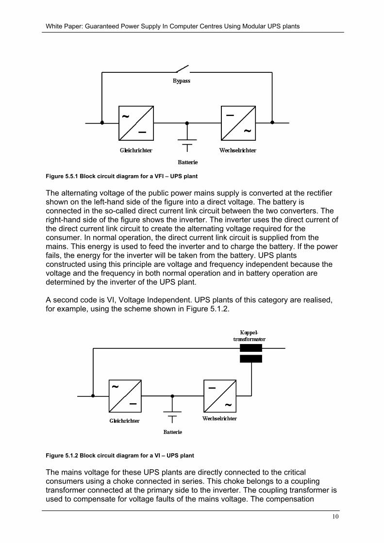
Figure 5.5.1 Block circuit diagram for a VFI – UPS plant
The alternating voltage of the public power mains supply is converted at the rectifiershown on the left-hand side of the figure into a direct voltage. The battery isconnected in the so-called direct current link circuit between the two converters. Theright-hand side of the figure shows the inverter. The inverter uses the direct current ofthe direct current link circuit to create the alternating voltage required for theconsumer. In normal operation, the direct current link circuit is supplied from themains. This energy is used to feed the inverter and to charge the battery. If the powerfails, the energy for the inverter will be taken from the battery. UPS plantsconstructed using this principle are voltage and frequency independent because thevoltage and the frequency in both normal operation and in battery operation aredetermined by the inverter of the UPS plant.
A second code is VI, Voltage Independent. UPS plants of this category are realised,for example, using the scheme shown in Figure 5.1.2.
Figure 5.1.2 Block circuit diagram for a VI – UPS plant
The mains voltage for these UPS plants are directly connected to the criticalconsumers using a choke connected in series. This choke belongs to a couplingtransformer connected at the primary side to the inverter. The coupling transformer isused to compensate for voltage faults of the mains voltage. The compensation
White Paper: Guaranteed Power Supply In Computer Centres Using Modular UPS plants
11
energy required here is supplied from the direct current link circuit via the inverter.The direct current link circuit with the associated battery is supplied from the mainsvia the rectifier. The UPS plant is independent of the voltage because it can use thecoupling transformer to catch any voltage fluctuations. Frequency fluctuations of themains, however, cannot be caught by this UPS plant because the load is directlycoupled with the supply mains.
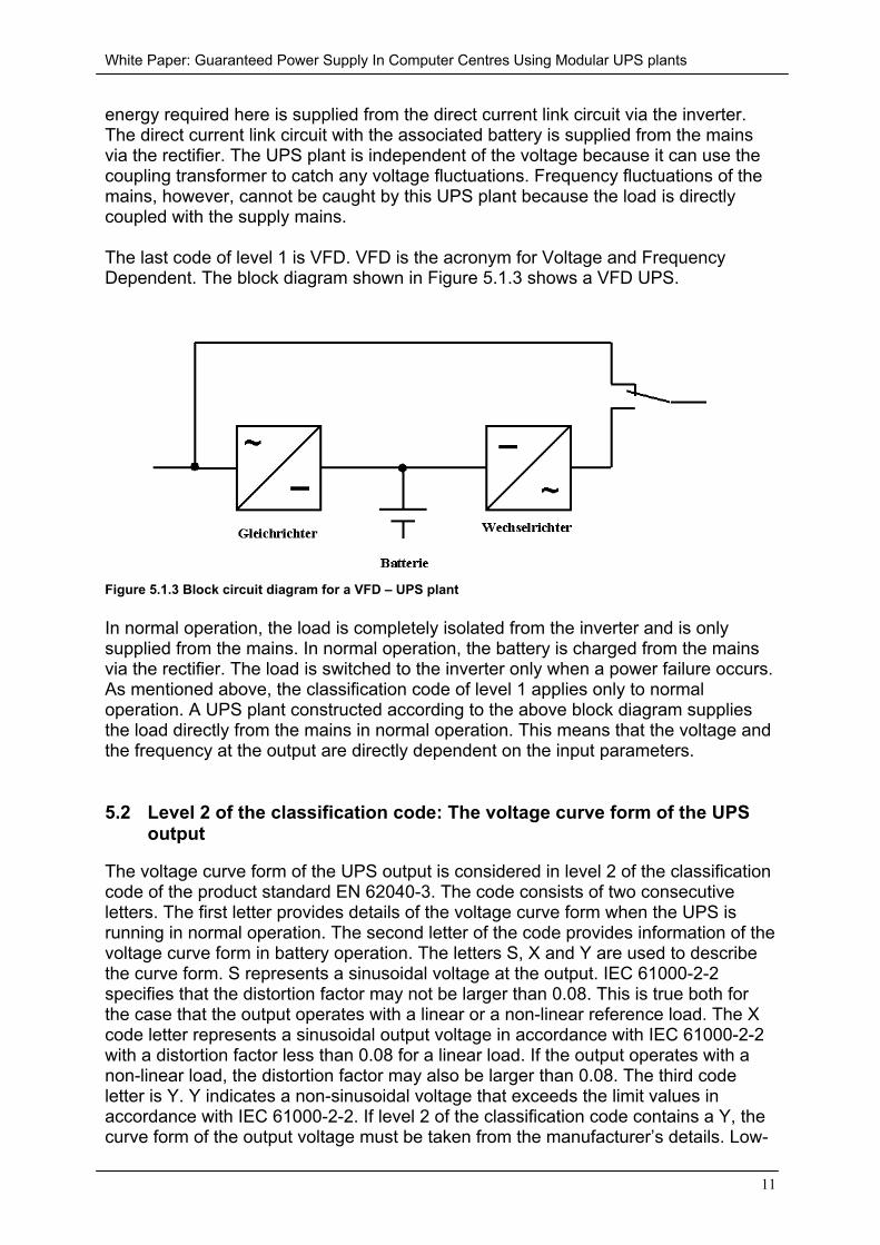
The last code of level 1 is VFD. VFD is the acronym for Voltage and FrequencyDependent. The block diagram shown in Figure 5.1.3 shows a VFD UPS.
Figure 5.1.3 Block circuit diagram for a VFD – UPS plant
In normal operation, the load is completely isolated from the inverter and is onlysupplied from the mains. In normal operation, the battery is charged from the mainsvia the rectifier. The load is switched to the inverter only when a power failure occurs.As mentioned above, the classification code of level 1 applies only to normaloperation. A UPS plant constructed according to the above block diagram suppliesthe load directly from the mains in normal operation. This means that the voltage andthe frequency at the output are directly dependent on the input parameters.
5.2 Level 2 of the classification code: The voltage curve form of the UPSoutput
The voltage curve form of the UPS output is considered in level 2 of the classificationcode of the product standard EN 62040-3. The code consists of two consecutiveletters. The first letter provides details of the voltage curve form when the UPS isrunning in normal operation. The second letter of the code provides information of thevoltage curve form in battery operation. The letters S, X and Y are used to describethe curve form. S represents a sinusoidal voltage at the output. IEC 61000-2-2specifies that the distortion factor may not be larger than 0.08. This is true both forthe case that the output operates with a linear or a non-linear reference load. The Xcode letter represents a sinusoidal output voltage in accordance with IEC 61000-2-2with a distortion factor less than 0.08 for a linear load. If the output operates with anon-linear load, the distortion factor may also be larger than 0.08. The third codeletter is Y. Y indicates a non-sinusoidal voltage that exceeds the limit values inaccordance with IEC 61000-2-2. If level 2 of the classification code contains a Y, thecurve form of the output voltage must be taken from the manufacturer’s details. Low-
White Paper: Guaranteed Power Supply In Computer Centres Using Modular UPS plants
12
cost UPS plants often supply rectangular or trapezoidal output voltages. Care mustbe taken here because certainly not all consumers can handle these voltage forms.
The explanation of level 2 of the classification code will now be completed with asmall example. If a UPS plant has the code letters SX for the output voltage form, theUPS plant in normal operation supplies a sinusoidal voltage with a distortion factorless than 0.08 in accordance with IEC 61000-2-2, irrespective of whether theconnected load is linear or non-linear. In battery operation, in contrast, the UPS cansupply a sinusoidal output voltage with a distortion factor less than 0.08 inaccordance with IEC 61000-2-2 only for a linear load. For a non-linear load, theoutput voltage in battery operation is no longer sinusoidal.
5.3 Level 3 of the classification code: The dynamic tolerance curves of theoutput
The 3rd level of the classification code in accordance with EN 62040-3 providesdetails of the dynamic behaviour of the UPS output. When different UPS plants arecompared, special attention should be paid to the 3rd level of the classification code,because this indicates whether the UPS plant really operates without interruption.The code for the dynamic tolerance curve of the output consists of three consecutivedigits. The first digit provides information about the behaviour of the output when theoperating mode changes. Thus, the voltage curve at the output is considered whenthe UPS plant changes from normal operation to battery operation or to some otherform between the normal operation, battery normal operation and mains operationoperating modes. The second digit specifies how the output of the UPS plant reactsfor load jumps with a linear load. The specified tolerance limit for the behaviour of theoutput must be observed for load jumps with linear load in normal operation and inbattery operation. Like the second digit, the third digit specifies the voltage change atthe UPS output for load jumps. The third digit differs from the second digit in that itprovides information about a load jump with a non-linear load. The tolerance rangemust also be observed in normal operation and battery operation.
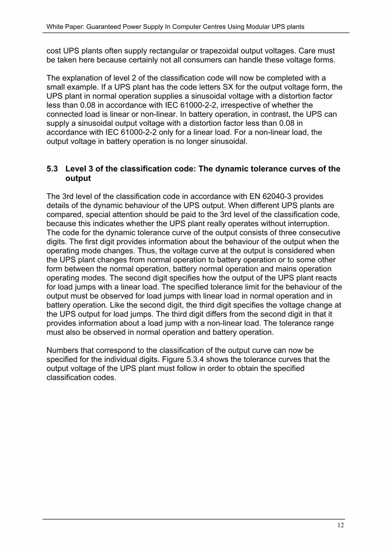
Numbers that correspond to the classification of the output curve can now bespecified for the individual digits. Figure 5.3.4 shows the tolerance curves that theoutput voltage of the UPS plant must follow in order to obtain the specifiedclassification codes.
White Paper: Guaranteed Power Supply In Computer Centres Using Modular UPS plants
13
Figure 5.3.4 Tolerance curves for the UPS classification of level 3
The figures show that only UPS plants with classification 1 really guarantee completefreedom from interruptions. UPS plants with classification 2 allow interruptions lastingas long as 1 ms. Classification 3 specifies the widest tolerance curve. Withinclassification 3, interruptions of the output voltage up to 10 ms are permitted. If themanufacturer cannot observe any of the tolerance curves, it can enter 4 for theclassification. In this case, the UPS user must request details of the dynamicbehaviour of the system from the manufacturer. To summarise, level 3 of theclassification code provides information about the quality of the output voltage underall operating conditions.
5.4 Which UPS plants protect against which mains faults?
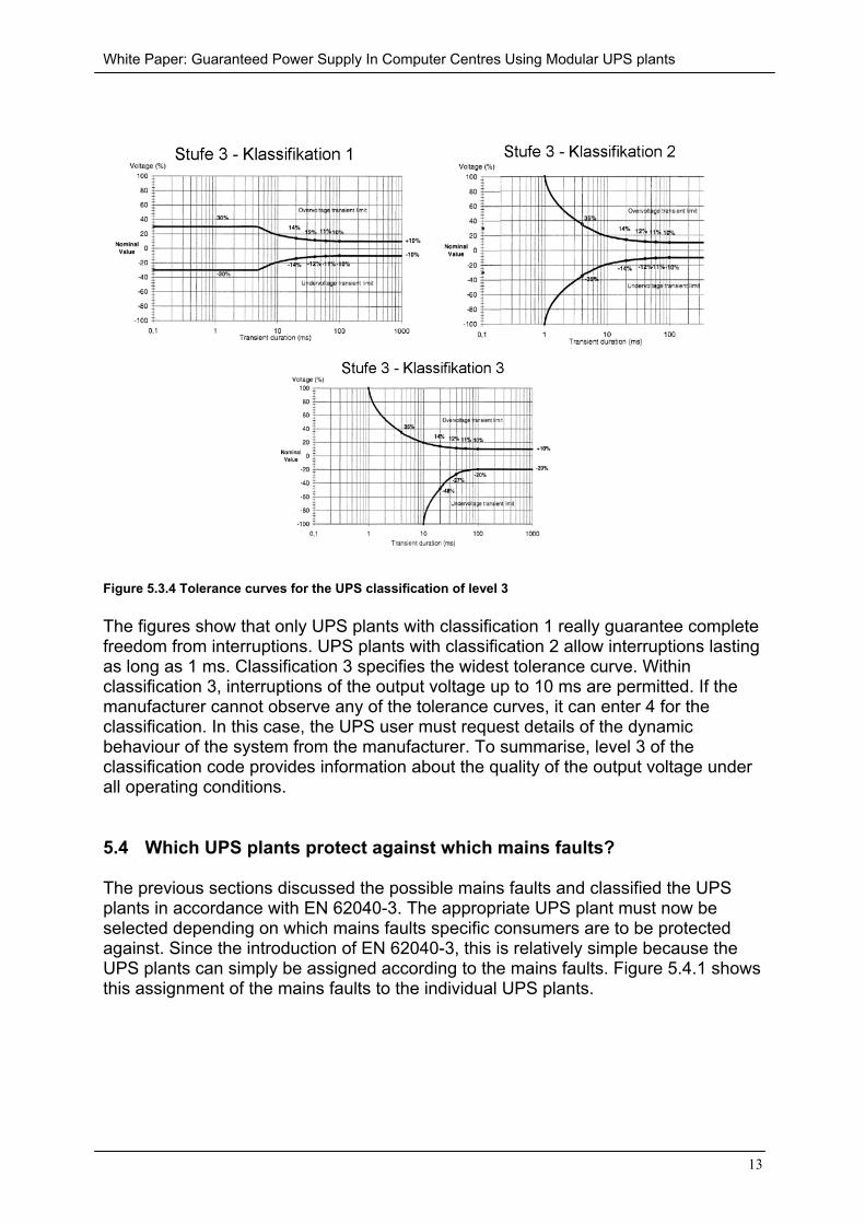
The previous sections discussed the possible mains faults and classified the UPSplants in accordance with EN 62040-3. The appropriate UPS plant must now beselected depending on which mains faults specific consumers are to be protectedagainst. Since the introduction of EN 62040-3, this is relatively simple because theUPS plants can simply be assigned according to the mains faults. Figure 5.4.1 showsthis assignment of the mains faults to the individual UPS plants.
White Paper: Guaranteed Power Supply In Computer Centres Using Modular UPS plants
14
Figure 5.4.1 Assignment of the mains faults to the UPS plants
VFI systems protect critical consumers from all 10 possible mains faults. VI systemsprotect against 5 of the 10 mains faults. VFD systems are poorest UPS plants. Theyprotect only against 3 of the 10 possible mains faults.
5.5 Assignment of the old designations for UPS plants to the classificationas specified by EN 62040-3
As mentioned previously, the terms used to differentiate the various UPStechnologies were not defined precisely. However, the terms will be assigned to theclassifications specified in EN 62040-3 in accordance to their most frequent use. Theterms stand-by, passive parallel operation or off-line are often used for VFD systems.The terms single conversion, active parallel operation or line-interactive UPS plantsare used for VI systems. The terms continuous operation, continuous converter oron-line are also known for UPS plants classified in the VFI category.
6 The battery as energy storage
The battery is the most critical component of a UPS plant. There are a wide range ofdifferent battery types available on the market. The appropriate battery type must beselected for each application. The following properties govern UPS plants. For 99.9%of the operating time, the UPS plant is supplied with power from the public mains.This means that the battery is kept fully charged for 99.9% of the time using acompensation charge. Should an exceptional condition cause a power failure of thepublic power supply, the battery will be discharged with very high currents within ashort time. Once the power failure is over, the battery will be recharged immediately.
White Paper: Guaranteed Power Supply In Computer Centres Using Modular UPS plants
15
These requirements cause significant problems for all battery types, although, leadbatteries can best meet these demands. Instead of the lead-acid batteries usedpreviously, maintenance-free lead-gel or lead absorbing pad batteries are normallyused nowadays. However, maintenance-free means by no means that no furtherattention needs to be paid to the batteries. Compared with conventional batteries,maintenance-free batteries differ only in no longer needing to be filled with water atregular intervals. As before, care should be taken to ensure that the correct chargingmanagement and the appropriate ambient temperature are used for the batteries.
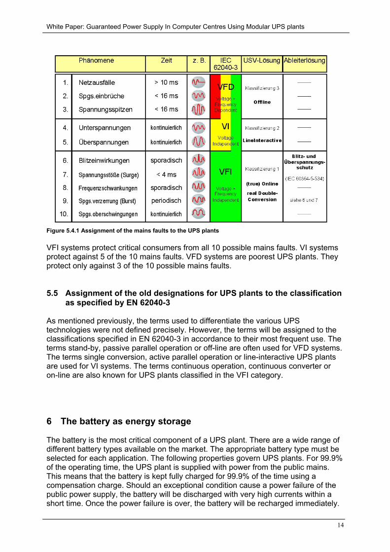
The battery manufacturers offer 10-year, 5-year and 3-year batteries. The lifetime,however, is based on an ambient temperature of 20° C. If, for example, a 10-yearbattery is operated at 30° C ambient temperature, the battery will only last 5 years.Figure 6.1 shows the relationship between the ambient temperature and life of thebattery.
Figure 6.1 Life expectation for VLRA batteries depending on the ambient temperature
7 Transformer-less UPS plants
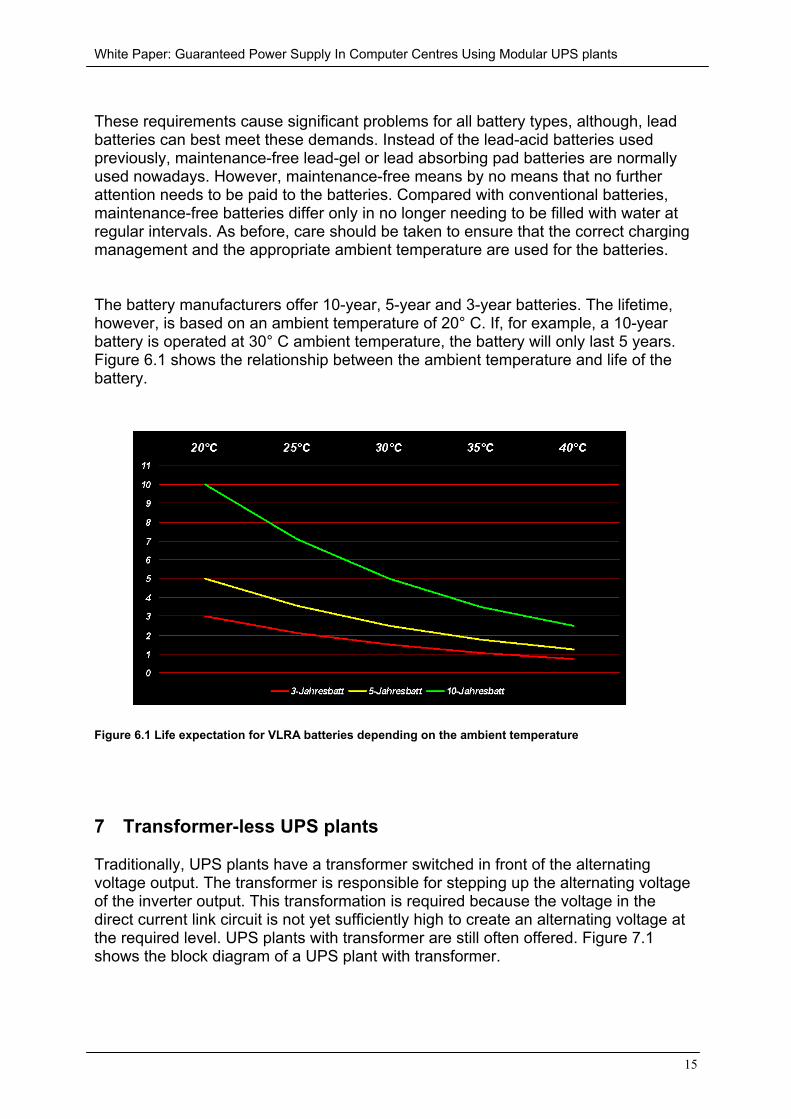
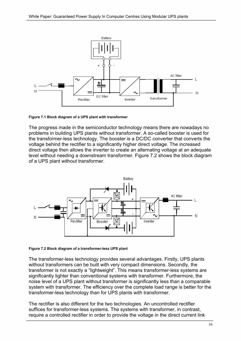
Traditionally, UPS plants have a transformer switched in front of the alternatingvoltage output. The transformer is responsible for stepping up the alternating voltageof the inverter output. This transformation is required because the voltage in thedirect current link circuit is not yet sufficiently high to create an alternating voltage atthe required level. UPS plants with transformer are still often offered. Figure 7.1shows the block diagram of a UPS plant with transformer.
White Paper: Guaranteed Power Supply In Computer Centres Using Modular UPS plants
16
Figure 7.1 Block diagram of a UPS plant with transformer
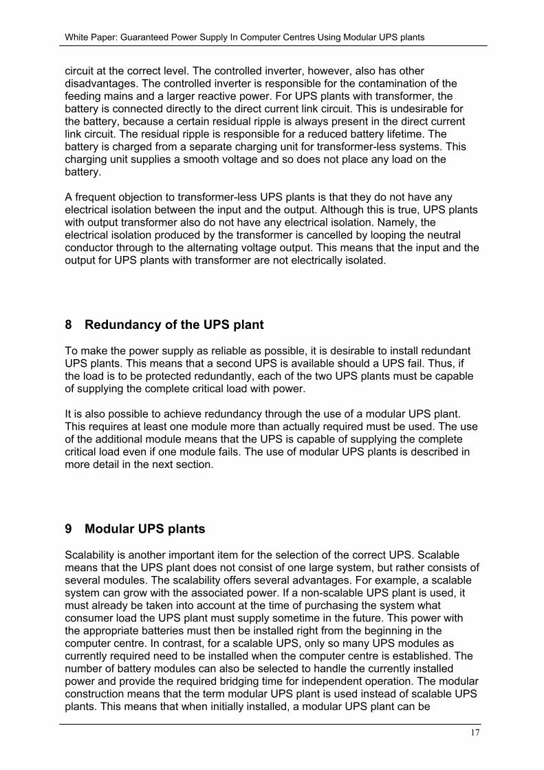
The progress made in the semiconductor technology means there are nowadays noproblems in building UPS plants without transformer. A so-called booster is used forthe transformer-less technology. The booster is a DC/DC converter that converts thevoltage behind the rectifier to a significantly higher direct voltage. The increaseddirect voltage then allows the inverter to create an alternating voltage at an adequatelevel without needing a downstream transformer. Figure 7.2 shows the block diagramof a UPS plant without transformer.
Figure 7.2 Block diagram of a transformer-less UPS plant
The transformer-less technology provides several advantages. Firstly, UPS plantswithout transformers can be built with very compact dimensions. Secondly, thetransformer is not exactly a “lightweight”. This means transformer-less systems aresignificantly lighter than conventional systems with transformer. Furthermore, thenoise level of a UPS plant without transformer is significantly less than a comparablesystem with transformer. The efficiency over the complete load range is better for thetransformer-less technology than for UPS plants with transformer.
The rectifier is also different for the two technologies. An uncontrolled rectifiersuffices for transformer-less systems. The systems with transformer, in contrast,require a controlled rectifier in order to provide the voltage in the direct current link
White Paper: Guaranteed Power Supply In Computer Centres Using Modular UPS plants
17
circuit at the correct level. The controlled inverter, however, also has otherdisadvantages. The controlled inverter is responsible for the contamination of thefeeding mains and a larger reactive power. For UPS plants with transformer, thebattery is connected directly to the direct current link circuit. This is undesirable forthe battery, because a certain residual ripple is always present in the direct currentlink circuit. The residual ripple is responsible for a reduced battery lifetime. Thebattery is charged from a separate charging unit for transformer-less systems. Thischarging unit supplies a smooth voltage and so does not place any load on thebattery.
A frequent objection to transformer-less UPS plants is that they do not have anyelectrical isolation between the input and the output. Although this is true, UPS plantswith output transformer also do not have any electrical isolation. Namely, theelectrical isolation produced by the transformer is cancelled by looping the neutralconductor through to the alternating voltage output. This means that the input and theoutput for UPS plants with transformer are not electrically isolated.
8 Redundancy of the UPS plant
To make the power supply as reliable as possible, it is desirable to install redundantUPS plants. This means that a second UPS is available should a UPS fail. Thus, ifthe load is to be protected redundantly, each of the two UPS plants must be capableof supplying the complete critical load with power.
It is also possible to achieve redundancy through the use of a modular UPS plant.This requires at least one module more than actually required must be used. The useof the additional module means that the UPS is capable of supplying the completecritical load even if one module fails. The use of modular UPS plants is described inmore detail in the next section.
9 Modular UPS plants
Scalability is another important item for the selection of the correct UPS. Scalablemeans that the UPS plant does not consist of one large system, but rather consists ofseveral modules. The scalability offers several advantages. For example, a scalablesystem can grow with the associated power. If a non-scalable UPS plant is used, itmust already be taken into account at the time of purchasing the system whatconsumer load the UPS plant must supply sometime in the future. This power withthe appropriate batteries must then be installed right from the beginning in thecomputer centre. In contrast, for a scalable UPS, only so many UPS modules ascurrently required need to be installed when the computer centre is established. Thenumber of battery modules can also be selected to handle the currently installedpower and provide the required bridging time for independent operation. The modularconstruction means that the term modular UPS plant is used instead of scalable UPSplants. This means that when initially installed, a modular UPS plant can be
White Paper: Guaranteed Power Supply In Computer Centres Using Modular UPS plants
18
significantly smaller than a non-modular UPS plant that must already handle all futurepower expansions.
In addition, the UPS batteries have only a limited lifetime. This means that non-modular UPS plants must install a large amount of battery capacity at the beginningwhich may possibly not be required and so costs unnecessary money. In addition,the redundancy for a modular UPS can be realised with less power than for aconventional UPS. For a modular UPS, the redundant power is the power stillavailable when a UPS module fails.
A small example illustrates this behaviour. The computer centre equipped with a UPSplant has a total connected load of 115 kVA. If we want to equip this computer centrewith a redundant conventional UPS plant, we need to install two UPS plants eachwith 120 kVA. This means that a complete UPS power of 240 kVA is installed. Thepower of the batteries attached to the UPS plants would then also suffice to providethe required standalone time with 240 kVA load.
If, in contrast, the 115 kVA load installed in the computer centre is to be handled by amodular UPS plant constructed from 40 kVA modules, then proceed as follows. Thesystem is built from four 40 kVA modules. This provides a total UPS power of 160kVA. If, a 40 kVA module now fails, the system with three 40 kVA modules is stillcapable of providing the installed power of 115 kVA. The UPS plant consisting of four40 kVA modules used here thus has a total power of 160 kVA or, however, aredundant power of 120 kVA. This clearly shows the advantage of the modular UPS.The complete installed power of the modular UPS plant lies significantly below thepower of the redundant conventional UPS plant. This also means that not so muchexcessive battery power needs to be provided than only required for the redundancy.
10 Calculation of the availability
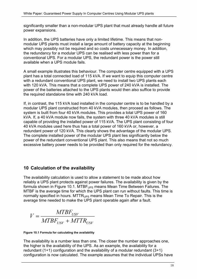
The availability calculation is used to allow a statement to be made about howreliably a UPS plant protects against power failures. The availability is given by theformula shown in Figure 10.1. MTBFUPS means Mean Time Between Failures. TheMTBF is the average time for which the UPS plant can run without faults. This time isnormally specified in hours. MTTRUPS means Mean Time To Repair. This is theaverage time needed to make the UPS plant operable again after a fault.
Figure 10.1 Formula for calculating the availability
The availability is a number less than one. The closer the number approaches one,the higher is the availability of the UPS. As an example, the availability for aredundant (1+1) configuration and the availability of a modular redundant (3+1)configuration is now calculated. The example assumes that the individual UPSs have
White Paper: Guaranteed Power Supply In Computer Centres Using Modular UPS plants
19
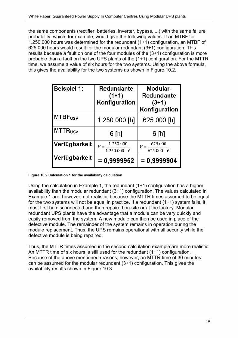
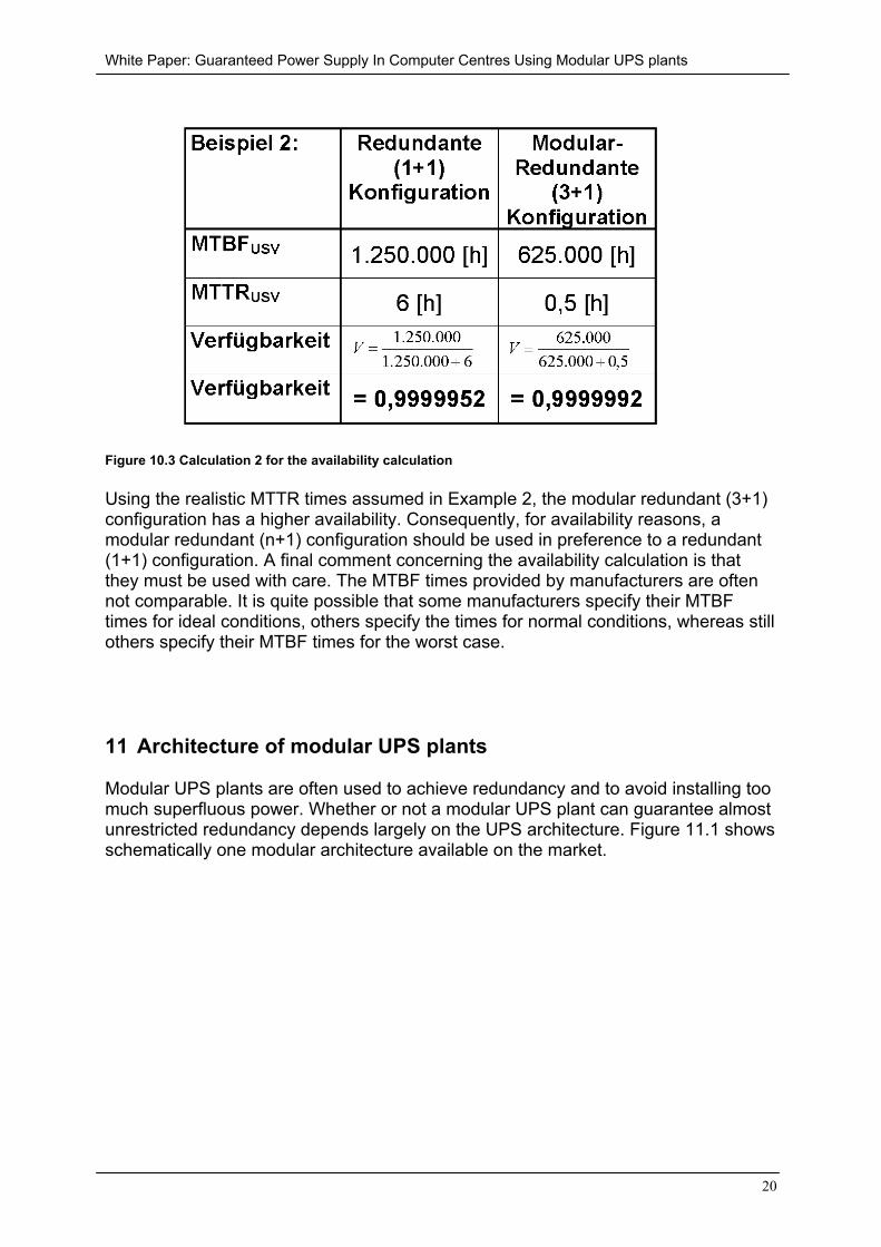
the same components (rectifier, batteries, inverter, bypass, ...) with the same failureprobability, which, for example, would give the following values. If an MTBF for1,250,000 hours was determined for the redundant (1+1) configuration, an MTBF of625,000 hours would result for the modular redundant (3+1) configuration. Thisresults because a fault on one of the four modules of the (3+1) configuration is moreprobable than a fault on the two UPS plants of the (1+1) configuration. For the MTTRtime, we assume a value of six hours for the two systems. Using the above formula,this gives the availability for the two systems as shown in Figure 10.2.
Figure 10.2 Calculation 1 for the availability calculation
Using the calculation in Example 1, the redundant (1+1) configuration has a higheravailability than the modular redundant (3+1) configuration. The values calculated inExample 1 are, however, not realistic, because the MTTR times assumed to be equalfor the two systems will not be equal in practice. If a redundant (1+1) system fails, itmust first be disconnected and then repaired on-site or at the factory. Modularredundant UPS plants have the advantage that a module can be very quickly andeasily removed from the system. A new module can then be used in place of thedefective module. The remainder of the system remains in operation during themodule replacement. Thus, the UPS remains operational with all security while thedefective module is being repaired.
Thus, the MTTR times assumed in the second calculation example are more realistic.An MTTR time of six hours is still used for the redundant (1+1) configuration.Because of the above mentioned reasons, however, an MTTR time of 30 minutescan be assumed for the modular redundant (3+1) configuration. This gives theavailability results shown in Figure 10.3.
White Paper: Guaranteed Power Supply In Computer Centres Using Modular UPS plants
20
Figure 10.3 Calculation 2 for the availability calculation
Using the realistic MTTR times assumed in Example 2, the modular redundant (3+1)configuration has a higher availability. Consequently, for availability reasons, amodular redundant (n+1) configuration should be used in preference to a redundant(1+1) configuration. A final comment concerning the availability calculation is thatthey must be used with care. The MTBF times provided by manufacturers are oftennot comparable. It is quite possible that some manufacturers specify their MTBFtimes for ideal conditions, others specify the times for normal conditions, whereas stillothers specify their MTBF times for the worst case.
11 Architecture of modular UPS plants
Modular UPS plants are often used to achieve redundancy and to avoid installing toomuch superfluous power. Whether or not a modular UPS plant can guarantee almostunrestricted redundancy depends largely on the UPS architecture. Figure 11.1 showsschematically one modular architecture available on the market.
White Paper: Guaranteed Power Supply In Computer Centres Using Modular UPS plants
21
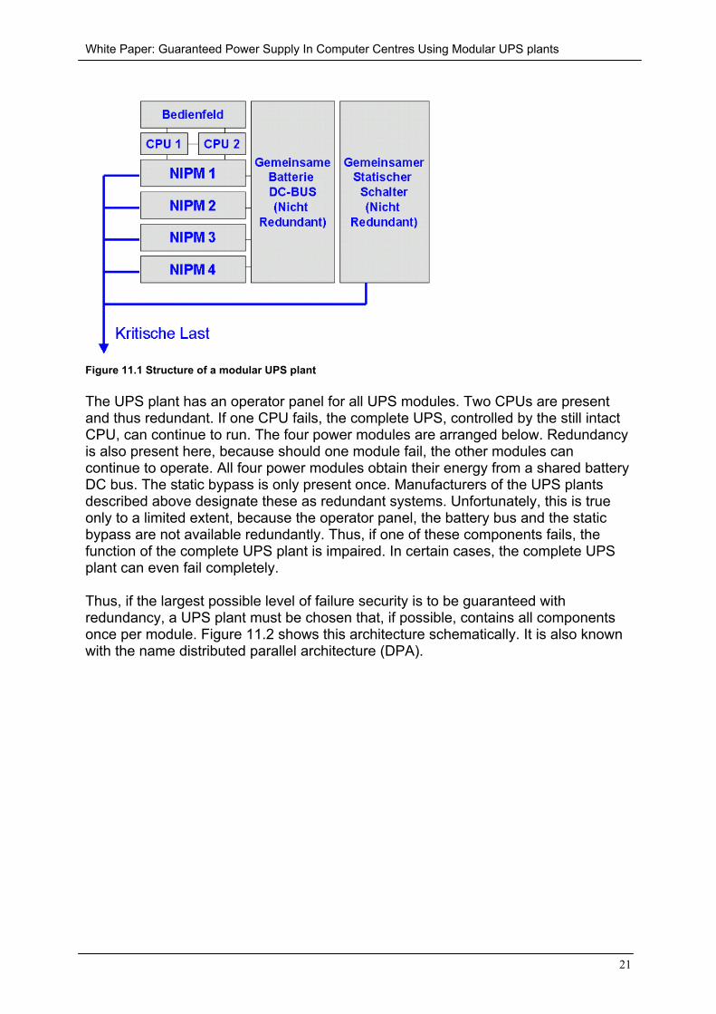
Figure 11.1 Structure of a modular UPS plant
The UPS plant has an operator panel for all UPS modules. Two CPUs are presentand thus redundant. If one CPU fails, the complete UPS, controlled by the still intactCPU, can continue to run. The four power modules are arranged below. Redundancyis also present here, because should one module fail, the other modules cancontinue to operate. All four power modules obtain their energy from a shared batteryDC bus. The static bypass is only present once. Manufacturers of the UPS plantsdescribed above designate these as redundant systems. Unfortunately, this is trueonly to a limited extent, because the operator panel, the battery bus and the staticbypass are not available redundantly. Thus, if one of these components fails, thefunction of the complete UPS plant is impaired. In certain cases, the complete UPSplant can even fail completely.
Thus, if the largest possible level of failure security is to be guaranteed withredundancy, a UPS plant must be chosen that, if possible, contains all componentsonce per module. Figure 11.2 shows this architecture schematically. It is also knownwith the name distributed parallel architecture (DPA).
White Paper: Guaranteed Power Supply In Computer Centres Using Modular UPS plants
22
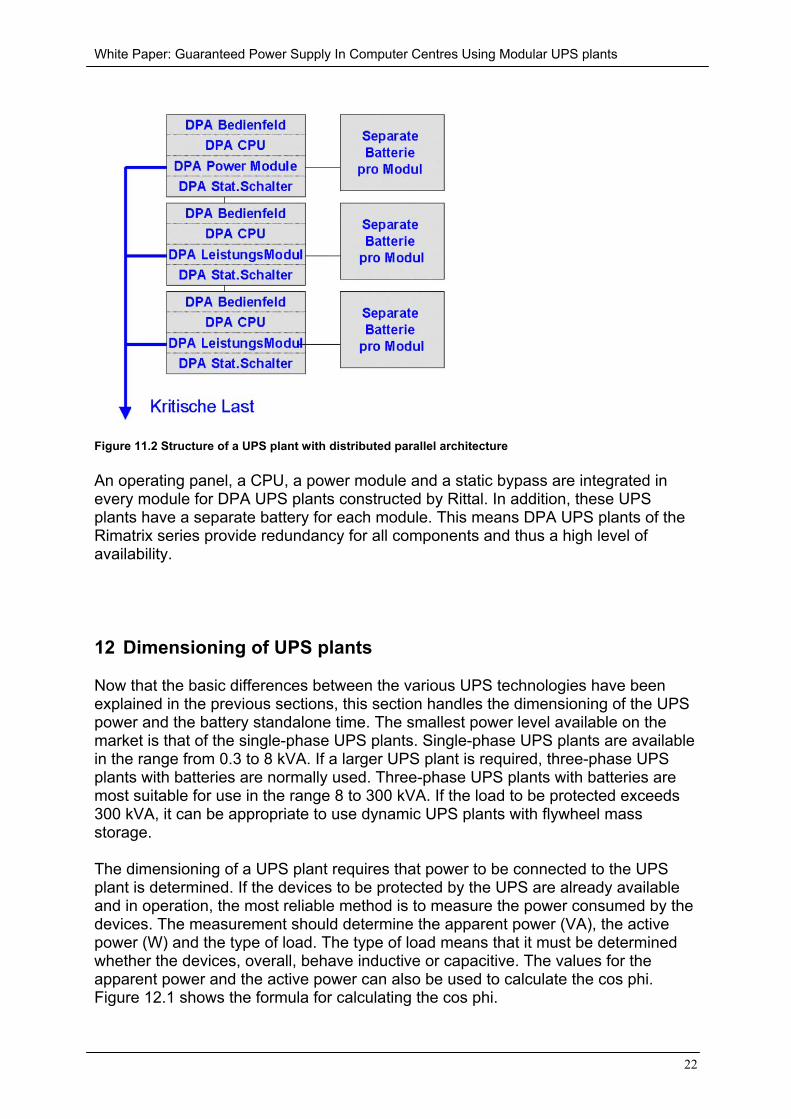
Figure 11.2 Structure of a UPS plant with distributed parallel architecture
An operating panel, a CPU, a power module and a static bypass are integrated inevery module for DPA UPS plants constructed by Rittal. In addition, these UPSplants have a separate battery for each module. This means DPA UPS plants of theRimatrix series provide redundancy for all components and thus a high level ofavailability.
12 Dimensioning of UPS plants
Now that the basic differences between the various UPS technologies have beenexplained in the previous sections, this section handles the dimensioning of the UPSpower and the battery standalone time. The smallest power level available on themarket is that of the single-phase UPS plants. Single-phase UPS plants are availablein the range from 0.3 to 8 kVA. If a larger UPS plant is required, three-phase UPSplants with batteries are normally used. Three-phase UPS plants with batteries aremost suitable for use in the range 8 to 300 kVA. If the load to be protected exceeds300 kVA, it can be appropriate to use dynamic UPS plants with flywheel massstorage.
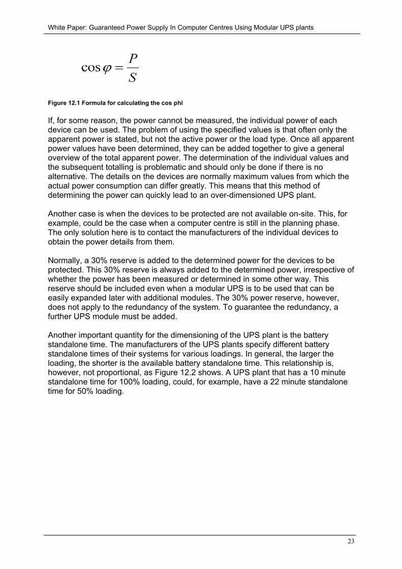
The dimensioning of a UPS plant requires that power to be connected to the UPSplant is determined. If the devices to be protected by the UPS are already availableand in operation, the most reliable method is to measure the power consumed by thedevices. The measurement should determine the apparent power (VA), the activepower (W) and the type of load. The type of load means that it must be determinedwhether the devices, overall, behave inductive or capacitive. The values for theapparent power and the active power can also be used to calculate the cos phi.Figure 12.1 shows the formula for calculating the cos phi.
White Paper: Guaranteed Power Supply In Computer Centres Using Modular UPS plants
23
Figure 12.1 Formula for calculating the cos phi
If, for some reason, the power cannot be measured, the individual power of eachdevice can be used. The problem of using the specified values is that often only theapparent power is stated, but not the active power or the load type. Once all apparentpower values have been determined, they can be added together to give a generaloverview of the total apparent power. The determination of the individual values andthe subsequent totalling is problematic and should only be done if there is noalternative. The details on the devices are normally maximum values from which theactual power consumption can differ greatly. This means that this method ofdetermining the power can quickly lead to an over-dimensioned UPS plant.
Another case is when the devices to be protected are not available on-site. This, forexample, could be the case when a computer centre is still in the planning phase.The only solution here is to contact the manufacturers of the individual devices toobtain the power details from them.
Normally, a 30% reserve is added to the determined power for the devices to beprotected. This 30% reserve is always added to the determined power, irrespective ofwhether the power has been measured or determined in some other way. Thisreserve should be included even when a modular UPS is to be used that can beeasily expanded later with additional modules. The 30% power reserve, however,does not apply to the redundancy of the system. To guarantee the redundancy, afurther UPS module must be added.
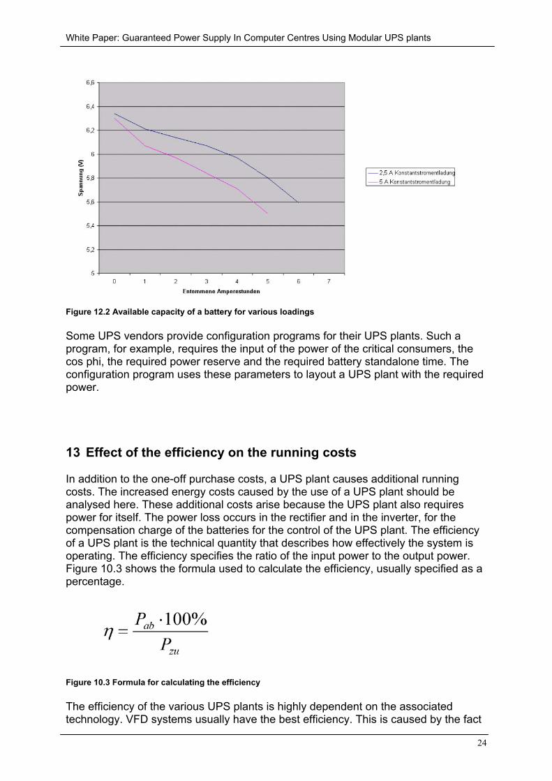
Another important quantity for the dimensioning of the UPS plant is the batterystandalone time. The manufacturers of the UPS plants specify different batterystandalone times of their systems for various loadings. In general, the larger theloading, the shorter is the available battery standalone time. This relationship is,however, not proportional, as Figure 12.2 shows. A UPS plant that has a 10 minutestandalone time for 100% loading, could, for example, have a 22 minute standalonetime for 50% loading.
White Paper: Guaranteed Power Supply In Computer Centres Using Modular UPS plants
24
Figure 12.2 Available capacity of a battery for various loadings
Some UPS vendors provide configuration programs for their UPS plants. Such aprogram, for example, requires the input of the power of the critical consumers, thecos phi, the required power reserve and the required battery standalone time. Theconfiguration program uses these parameters to layout a UPS plant with the requiredpower.
13 Effect of the efficiency on the running costs
In addition to the one-off purchase costs, a UPS plant causes additional runningcosts. The increased energy costs caused by the use of a UPS plant should beanalysed here. These additional costs arise because the UPS plant also requirespower for itself. The power loss occurs in the rectifier and in the inverter, for thecompensation charge of the batteries for the control of the UPS plant. The efficiencyof a UPS plant is the technical quantity that describes how effectively the system isoperating. The efficiency specifies the ratio of the input power to the output power.Figure 10.3 shows the formula used to calculate the efficiency, usually specified as apercentage.
Figure 10.3 Formula for calculating the efficiency
The efficiency of the various UPS plants is highly dependent on the associatedtechnology. VFD systems usually have the best efficiency. This is caused by the fact
White Paper: Guaranteed Power Supply In Computer Centres Using Modular UPS plants
25
that the system is activated only in the case of a power failure and thus the inverteronly needs to operate when a power failure has occurred. This means that theinverter causes power loss only when there is a power failure. Despite the relativelygood efficiency, however, it should not be forgotten that VFD systems provideprotection for only three of the ten possible mains faults. Although the efficiency of VIsystems is significantly poorer than that for VFD systems, it is usually better than thatfor VFI systems.
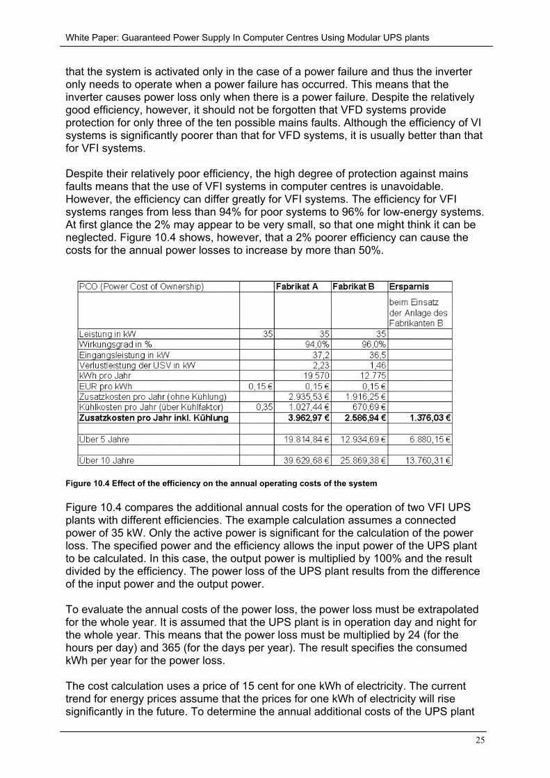
Despite their relatively poor efficiency, the high degree of protection against mainsfaults means that the use of VFI systems in computer centres is unavoidable.However, the efficiency can differ greatly for VFI systems. The efficiency for VFIsystems ranges from less than 94% for poor systems to 96% for low-energy systems.At first glance the 2% may appear to be very small, so that one might think it can beneglected. Figure 10.4 shows, however, that a 2% poorer efficiency can cause thecosts for the annual power losses to increase by more than 50%.
Figure 10.4 Effect of the efficiency on the annual operating costs of the system
Figure 10.4 compares the additional annual costs for the operation of two VFI UPSplants with different efficiencies. The example calculation assumes a connectedpower of 35 kW. Only the active power is significant for the calculation of the powerloss. The specified power and the efficiency allows the input power of the UPS plantto be calculated. In this case, the output power is multiplied by 100% and the resultdivided by the efficiency. The power loss of the UPS plant results from the differenceof the input power and the output power.
To evaluate the annual costs of the power loss, the power loss must be extrapolatedfor the whole year. It is assumed that the UPS plant is in operation day and night forthe whole year. This means that the power loss must be multiplied by 24 (for thehours per day) and 365 (for the days per year). The result specifies the consumedkWh per year for the power loss.
The cost calculation uses a price of 15 cent for one kWh of electricity. The currenttrend for energy prices assume that the prices for one kWh of electricity will risesignificantly in the future. To determine the annual additional costs of the UPS plant
White Paper: Guaranteed Power Supply In Computer Centres Using Modular UPS plants
26
without cooling loss, the number of kWh must be multiplied with the costs for oneKWh.
The majority of the power loss of the UPS plant is converted into heat. To ensure thatthe temperature does not become too high and the used devices do not suffer a heatdeath, the room that contains the UPS plant must be cooled. The cooling causesadditional energy costs that are proportional to the power loss of the UPS plant. Theproportionality means that the calculation of the cooling costs can simply beprocessed using a factor. The cooling costs result by multiplying the additional costswithout cooling by the cooling factor. The example calculation uses a realistic valueof 0.35 for the cooling factor. The annual additional costs including the cooling costsare determined from the sum of the additional costs per year (without cooling) andthe cooling costs.
The above example shows that even a difference of the efficiency of only 2percentage points causes significantly different costs. More precisely, for theoperation of the system made by manufacturer A means more than 53% more mustbe paid for energy compared with the operation of the system made by manufacturerB. Even the relatively low connected power used in the example calculation, the UPSplant with the better efficiency has an annual energy cost saving of almost € 1400.There are correspondingly larger sums for the operation of the UPS plant over 5 or10 years. Once again, we emphasise that the efficiency for the selection of a UPSplant is an important economic quantity.
14 Management of the UPS plant
Because the UPS plant is a critical security component, it should also be managed.Most UPS plants can be managed using three interfaces. The first interface are thepotential free contacts. The potential free contacts can be used to forward a fewstatus messages from the UPS. Usually, the messages mains failure, load beingsupplied from the inverter, battery discharged, USV is in bypass operation and ageneral alarm message are each provided at a contact. The UPS can also beswitched into bypass operation using an input.
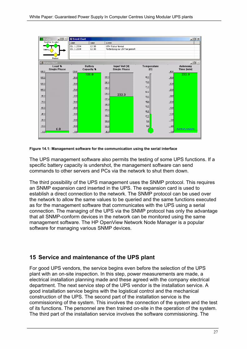
Most UPS plants also provide a serial interface. A PC with a UPS managementprogram used to obtain a wide range of information from the UPS can be connectedto this serial interface. The management program indicates the current operatingstate of the UPS. The loading current, the current battery capacity, the input voltage,the temperature and the battery standalone time for the currently connected load canbe shown. These values are also shown in Figure 14.1.
White Paper: Guaranteed Power Supply In Computer Centres Using Modular UPS plants
27
Figure 14.1: Management software for the communication using the serial interface
The UPS management software also permits the testing of some UPS functions. If aspecific battery capacity is undershot, the management software can sendcommands to other servers and PCs via the network to shut them down.
The third possibility of the UPS management uses the SNMP protocol. This requiresan SNMP expansion card inserted in the UPS. The expansion card is used toestablish a direct connection to the network. The SNMP protocol can be used overthe network to allow the same values to be queried and the same functions executedas for the management software that communicates with the UPS using a serialconnection. The managing of the UPS via the SNMP protocol has only the advantagethat all SNMP-conform devices in the network can be monitored using the samemanagement software. The HP OpenView Network Node Manager is a popularsoftware for managing various SNMP devices.
15 Service and maintenance of the UPS plant
For good UPS vendors, the service begins even before the selection of the UPSplant with an on-site inspection. In this step, power measurements are made, aelectrical installation planning made and these agreed with the company electricaldepartment. The next service step of the UPS vendor is the installation service. Agood installation service begins with the logistical control and the mechanicalconstruction of the UPS. The second part of the installation service is thecommissioning of the system. This involves the connection of the system and the testof its functions. The personnel are then trained on-site in the operation of the system.The third part of the installation service involves the software commissioning. The
White Paper: Guaranteed Power Supply In Computer Centres Using Modular UPS plants
28
software will be installed and the system customised. The software is then integratedin the network and the IT representatives trained in the operation of the software.
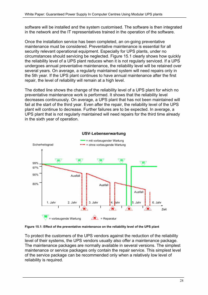
Once the installation service has been completed, an on-going preventativemaintenance must be considered. Preventative maintenance is essential for allsecurity relevant operational equipment. Especially for UPS plants, under nocircumstances should servicing be neglected. Figure 15.1 clearly shows how quicklythe reliability level of a UPS plant reduces when it is not regularly serviced. If a UPSundergoes annual preventative maintenance, the reliability level will be retained overseveral years. On average, a regularly maintained system will need repairs only inthe 5th year. If the UPS plant continues to have annual maintenance after the firstrepair, the level of reliability will remain at a high level.
The dotted line shows the change of the reliability level of a UPS plant for which nopreventative maintenance work is performed. It shows that the reliability leveldecreases continuously. On average, a UPS plant that has not been maintained willfail at the start of the third year. Even after the repair, the reliability level of the UPSplant will continue to decrease. Further failures are to be expected. In average, aUPS plant that is not regularly maintained will need repairs for the third time alreadyin the sixth year of operation.
Figure 15.1: Effect of the preventative maintenance on the reliability level of the UPS plant
To protect the customers of the UPS vendors against the reduction of the reliabilitylevel of their systems, the UPS vendors usually also offer a maintenance package.The maintenance packages are normally available in several versions. The simplestmaintenance or service packages only contain the repair service. This simplest levelof the service package can be recommended only when a relatively low level ofreliability is required.
White Paper: Guaranteed Power Supply In Computer Centres Using Modular UPS plants
29
Better maintenance packages always include an annual preventative maintenance.The maintenance packages can also include different repair response times. Therepair response time is the time between the arrival of the fault report at the servicecompany until the start of repairs on the UPS plant at the customer location. For highavailability there are maintenance packages with response times of 4 hours.However, the response time should not exceed 48 hours even for simpler servicepackages. The best maintenance packages include the costs for the labour andtravel, and any required parts subject to wear. The UPS vendors thus give theircustomers with the various versions of the maintenance packages the possibility topurchase the package appropriate for their specific requirement.
16 Summary
The first sections of this white paper showed that a UPS plant is essential in manyareas. The subsequent sections indicate which properties differentiate the systemscurrently available on the market and why particular value must be placed on whichproperties. Currently only UPS plants that conform to EN 62040-3 of the class VFISS 111 can be recommended for all critical areas. The use of transformer-lessvariants is recommended because this makes the systems lighter, more compact andsignificantly quieter in operation. Furthermore, the transformer-less technologynormally has a significantly better efficiency than UPS plants with transformer. Theexample calculation shows unambiguously how important a good efficiency is forreducing the operating costs for the UPS plant.
To protect the investment in the UPS plant, a scalable UPS plant should always bechosen. This allows the UPS power to grow with the power of the connected criticalload. To further increase the reliability level provided by the UPS plant, redundancyshould be provided. The redundancy can best be achieved through the use ofmodular n+1 systems. It is important for the redundancy that all components arereally present once per module. This is only the case for systems with the so-calleddistributed parallel architecture (DPA) as provided by Rittal.
The UPS vendors can provide support for the dimensioning the UPS plant. Theconfiguration programs offered by many manufacturers can also be useful for thedimensioning of the UPS plant. To ensure the level of reliability of the system evenafter years of operation, a good maintenance and service package should also beordered when the UPS plant is purchased.
Rittal Corp. with RimatriX5 presents a system solution concept that provides thecomplete physical IT infrastructure. With this solution system, Rittal covers the areasRack, Power, Cooling and Security. In the power area, Rittal with the Power ModularConcept (PMC) offers a modern UPS plant. The Power Modular Concept satisfies allrequirements for a flexible and fail-safe UPS plant.
Germany’s largest design office for IT computer centres has prepared a study for theRimatriX5 concept. This states: “The market also gets an integrated and high-qualitysolution from the low voltage main distribution through to the power connections forthe end devices”.
White Paper: Guaranteed Power Supply In Computer Centres Using Modular UPS plants
30
The leading design office wrote the following about the UPS plant: “The modularconstruction permits a simple customisation to meet the actually needed power”. Thispositively affects the energy balance and thus the economics. The expansion withindividual UPS modules is significantly simpler than for conventional solutions andcan be performed without impairing the running system.”
To summarise, the independent design office made the following judgement:
“We consider the Rittal PMC system as being an interesting and innovative solutionwith good market chances compared with conventional systems.”