Embed Size (px)
Citation preview
GTZ MANUAL BOOK
FOR
MOULD PRODUCTION OF JIKO KISASA AND ROCKET MOULDS.
A DETAILED MANUAL FOR A HIGH STANDARD AND
ACCURATE MOULD PRODUCTION.
2
USE OF THIS MANUAL This manual has been produced by qualified technicians on Mould
production, product research, product development and technical drawing.
The dimensions in this book has been practically tested to be productively
functional and therefore does not need any further test and research to
produce the same.
The use of this book in mould production is therefore recommended by all
standards.
Any part of this book MAY be reproduced or transmitted in any form or by
any means including photocopying. Provided the producers are
acknowledged. However, the authors of this book will NOT take any
responsibility in case asubstandared product is produced as a result of any
alterations or misinterpretation of this manual or the technical drawings
contained herein
No organization or individual who reproduces or copies any part of this
book may claim exclusive rights thereto. Any materials reproduced or
copied from this book shall be subjected to the same limitations in respect of
sale and use as set out above.
3
PREFACE
Moulds have been identified as the most accurate and efficient means of
producing quality products of any design, the production of both Rocket
and Jiko Kisasa moulds are therefore no exception . It has been identified
that the moulds, when designed accurately according to specification,
produce a standard product with accurate measurements and dimension
which may be difficult to produce without the help of mould.
The Jiko Kisasa and Rocket stove mould are more technically designed in a
way that makes using them more productive and the products are therefore
quality and accurate. The demand for Jiko kisasa and Rocket Jiko are high ,
it is therefore essential that the training on the production of the mould
be done to as many people as possible so that they can meet the market
demand. However, the market also demands quality products that meet the
expectation of the consumers hence the production of this manual.
The dimensions and technical drawings in this book are in millimeters
unless stated otherwise, in case the user of this book may not be well
conversant with the stated measurement, their own translation will be
advised only if it is accurate and reflect the same in its original
measurements.
It is worth noting that the dimensions of the rocket moulds have undergone some changes
in measurements, these changes have been necessitated by consumer comments and
market demand, hence the reproduction of the report and manual.
4
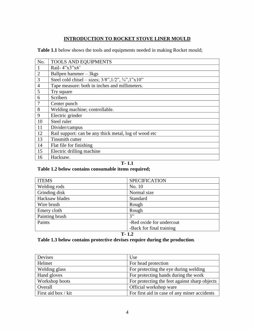
INTRODUCTION TO ROCKET STOVE LINER MOULD
Table 1.1 below shows the tools and equipments needed in making Rocket mould;
No. TOOLS AND EQUIPMENTS
1 Rail- 4”x3”x6’
2 Ballpen hammer – 3kgs
3 Steel cold chisel – sizes; 3/8”,1/2”, ¾”,1”x10”
4 Tape measure: both in inches and millimeters.
5 Try square
6 Scribers
7 Center punch
8 Welding machine; controllable.
9 Electric grinder
10 Steel ruler
11 Divider/campus
12 Rail support: can be any thick metal, log of wood etc
13 Tinsmith cutter
14 Flat file for finishing
15 Electric drilling machine
16 Hacksaw.
T- 1.1
Table 1.2 below contains consumable items required;
ITEMS SPECIFICATION
Welding rods No. 10
Grinding disk Normal size
Hacksaw blades Standard
Wire brush Rough
Emery cloth Rough
Painting brush 3”
Paints -Red oxide for undercoat
-Back for final training
T- 1.2
Table 1.3 below contains protective devises require during the production.
Devises Use
Helmet For head protection
Welding glass For protecting the eye during welding
Hand gloves For protecting hands during the work
Workshop boots For protecting the feet against sharp objects
Overall Official workshop ware
First aid box / kit For first aid in case of any miner accidents
5
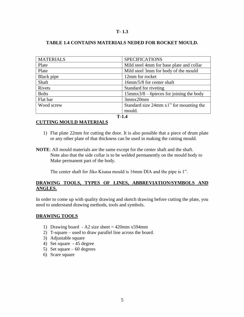
T- 1.3
TABLE 1.4 CONTAINS MATERIALS NEDED FOR ROCKET MOULD.
MATERIALS SPECIFICATIONS
Plate Mild steel 4mm for base plate and collar
Plate Mild steel 3mm for body of the mould
Black pipe 12mm for rocket
Shaft 16mm/5/8 for center shaft
Rivets Standard for riveting
Bolts 15mmx3/8 – 6pieces for joining the body
Flat bar 3mmx20mm
Wood screw Standard size 24mm x1” for mounting the
mould.
T-1.4
CUTTING MOULD MATERIALS
1) Flat plate 22mm for cutting the door. It is also possible that a piece of drum plate
or any other plate of that thickness can be used in making the cutting mould.
NOTE: All mould materials are the same except for the center shaft and the shaft.
Note also that the side collar is to be welded permanently on the mould body to
Make permanent part of the body.
The center shaft for Jiko Kisasa mould is 16mm DIA and the pipe is 1”.
DRAWING TOOLS, TYPES OF LINES, ABBREVIATION/SYMBOLS AND
ANGLES.
In order to come up with quality drawing and sketch drawing before cutting the plate, you
need to understand drawing methods, tools and symbols.
DRAWING TOOLS
1) Drawing board - A2 size sheet = 420mm x594mm
2) T-square – used to draw parallel line across the board.
3) Adjustable square
4) Set square - 45 degree
5) Set square – 60 degrees
6) Scare square
6
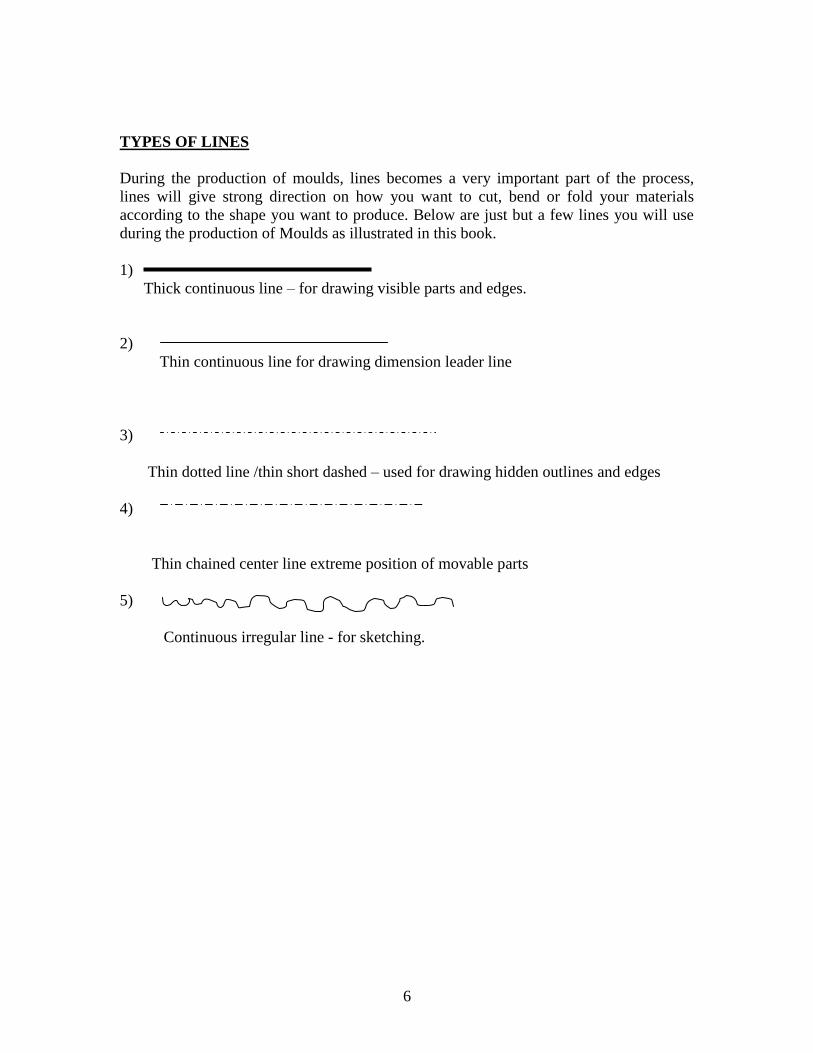
TYPES OF LINES
During the production of moulds, lines becomes a very important part of the process,
lines will give strong direction on how you want to cut, bend or fold your materials
according to the shape you want to produce. Below are just but a few lines you will use
during the production of Moulds as illustrated in this book.
1)
Thick continuous line – for drawing visible parts and edges.
2)
Thin continuous line for drawing dimension leader line
3)
Thin dotted line /thin short dashed – used for drawing hidden outlines and edges
4)
Thin chained center line extreme position of movable parts
5)
Continuous irregular line - for sketching.
7
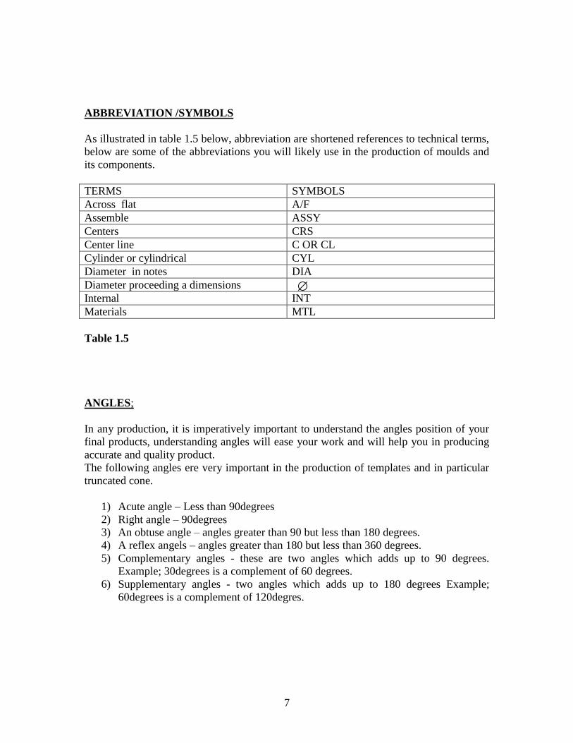
ABBREVIATION /SYMBOLS
As illustrated in table 1.5 below, abbreviation are shortened references to technical terms,
below are some of the abbreviations you will likely use in the production of moulds and
its components.
TERMS SYMBOLS
Across flat A/F
Assemble ASSY
Centers CRS
Center line C OR CL
Cylinder or cylindrical CYL
Diameter in notes DIA
Diameter proceeding a dimensions
Internal INT
Materials MTL
Table 1.5
ANGLES;
In any production, it is imperatively important to understand the angles position of your
final products, understanding angles will ease your work and will help you in producing
accurate and quality product.
The following angles ere very important in the production of templates and in particular
truncated cone.
1) Acute angle – Less than 90degrees
2) Right angle – 90degrees
3) An obtuse angle – angles greater than 90 but less than 180 degrees.
4) A reflex angels – angles greater than 180 but less than 360 degrees.
5) Complementary angles - these are two angles which adds up to 90 degrees.
Example; 30degrees is a complement of 60 degrees.
6) Supplementary angles - two angles which adds up to 180 degrees Example;
60degrees is a complement of 120degres.
8
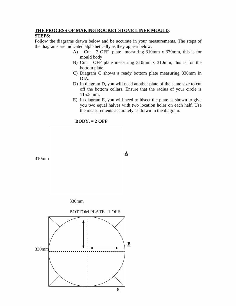
THE PROCESS OF MAKING ROCKET STOVE LINER MOULD.
STEPS;
Follow the diagrams drawn below and be accurate in your measurements. The steps of
the diagrams are indicated alphabetically as they appear below.
A) – Cut 2 OFF plate measuring 310mm x 330mm, this is for
mould body
B) Cut 1 OFF plate measuring 310mm x 310mm, this is for the
bottom plate.
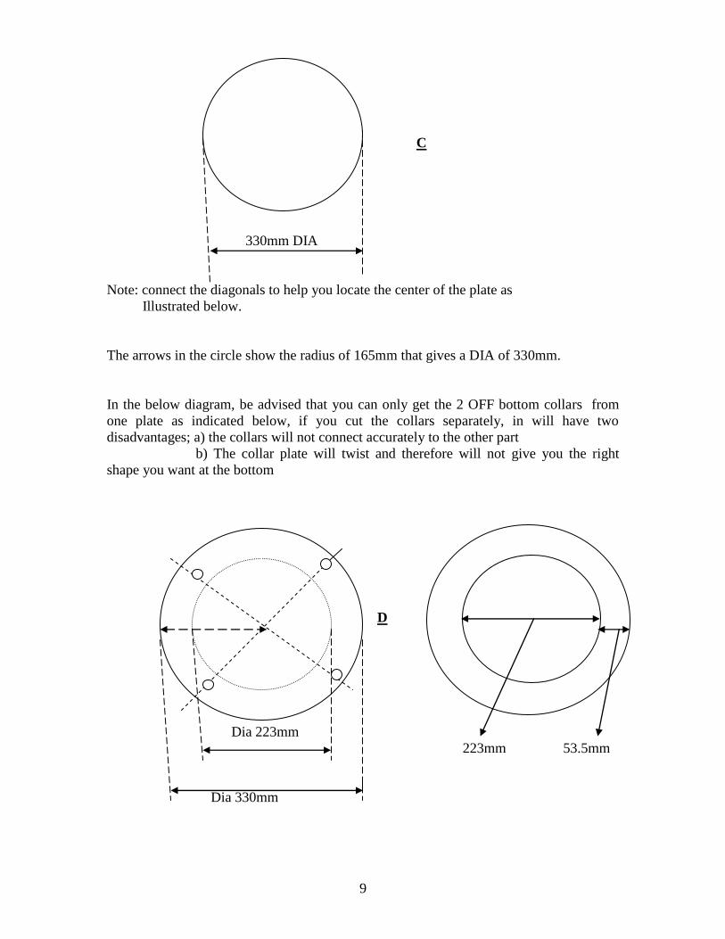
C) Diagram C shows a ready bottom plate measuring 330mm in
DIA.
D) In diagram D, you will need another plate of the same size to cut
off the bottom collars. Ensure that the radius of your circle is
115.5 mm.
E) In diagram E, you will need to bisect the plate as shown to give
you two equal halves with two location holes on each half. Use
the measurements accurately as drawn in the diagram.
BODY. = 2 OFF
Aa A
310mm
330mm
BOTTOM PLATE 1 OFF
B
330mm
9
C
330mm DIA
Note: connect the diagonals to help you locate the center of the plate as
Illustrated below.
The arrows in the circle show the radius of 165mm that gives a DIA of 330mm.
In the below diagram, be advised that you can only get the 2 OFF bottom collars from
one plate as indicated below, if you cut the collars separately, in will have two
disadvantages; a) the collars will not connect accurately to the other part
b) The collar plate will twist and therefore will not give you the right
shape you want at the bottom
D
Dia 223mm
223mm 53.5mm
Dia 330mm
10
BOTTOM COLLAR 2 OFF
E
223mm
330mm
Location pins 4 OFF location bolts 6 OFF
Vertical collar 4 OFF
150mm 150mm
F
30mm
290mm
THE PROCEDURE OF MAKING ROCKET LINER MOULD.
1) Place the flat metal sheet on a rail, use your pall pain hammer and fold the plate
into halves.
G Plate
- Rail.
2) Hit the plate and make it round and even semi- circle of 2 OFF.
Joints of plate 1&2
11
200mm 200mmDIA
H I 2 OFF
Plate 1
Plate 2
2 OFF plate joined together
NOTE: location pins, location and location holes MUST be 10mm in sizes.
150mm 150mm
A
B
C
150mm 150mm
A – 330mm in DIA
B – 300mm in DIA
C- 250mm in DIA.
Vertical
collar
12
Paddle pipe 1 OFF. Paddle handle 1 OFF paddle plate1 OFF
130mm
` 35m
20mm
2
345 70mm
360 mm 310mm
Paddle web reinforcement center shaft 1 OFF.
300mm
308mm 15mm
60mm
15mm 16mm D
Paddle handle.
120mm
240mm
15mm
13
A
C E B
D
G H
I
J
L
K
14
NOTE; The parts of the Rocket stove mould above are explained here below:
A – Paddle handle – 310mm
B – Paddle reinforcement – 308mm
C – Paddle pipe – 360mm
D – Paddle plate – 345mm
E – Bottom plate- 330mm D
F – Location holes- 10mm D
G – Center shaft – 300mm
H – Location pin- 15mm
I – Vertical collar- 290mm
J – Mould body – 220 D
K – Bottom collar- See E above.
L – Bottom location hole – 10mm D
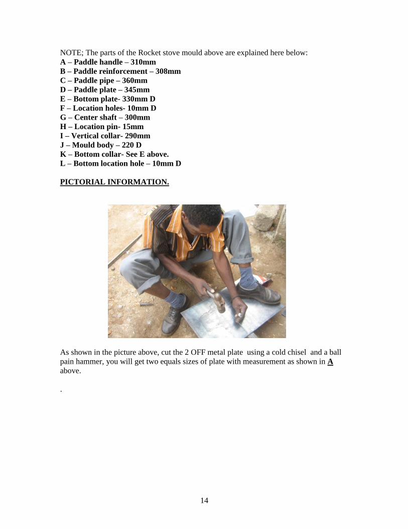
PICTORIAL INFORMATION.
As shown in the picture above, cut the 2 OFF metal plate using a cold chisel and a ball
pain hammer, you will get two equals sizes of plate with measurement as shown in A
above.
.
15
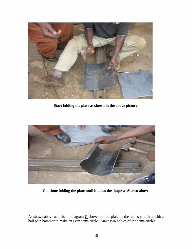
Start folding the plate as shown in the above picture.
Continue folding the plate until it takes the shape as Shawn above.
As shown above and also in diagram G above, roll the plate on the rail as you hit it with a
ball pain hammer to make an even semi-circle. Make two halves of the semi-circles.
16
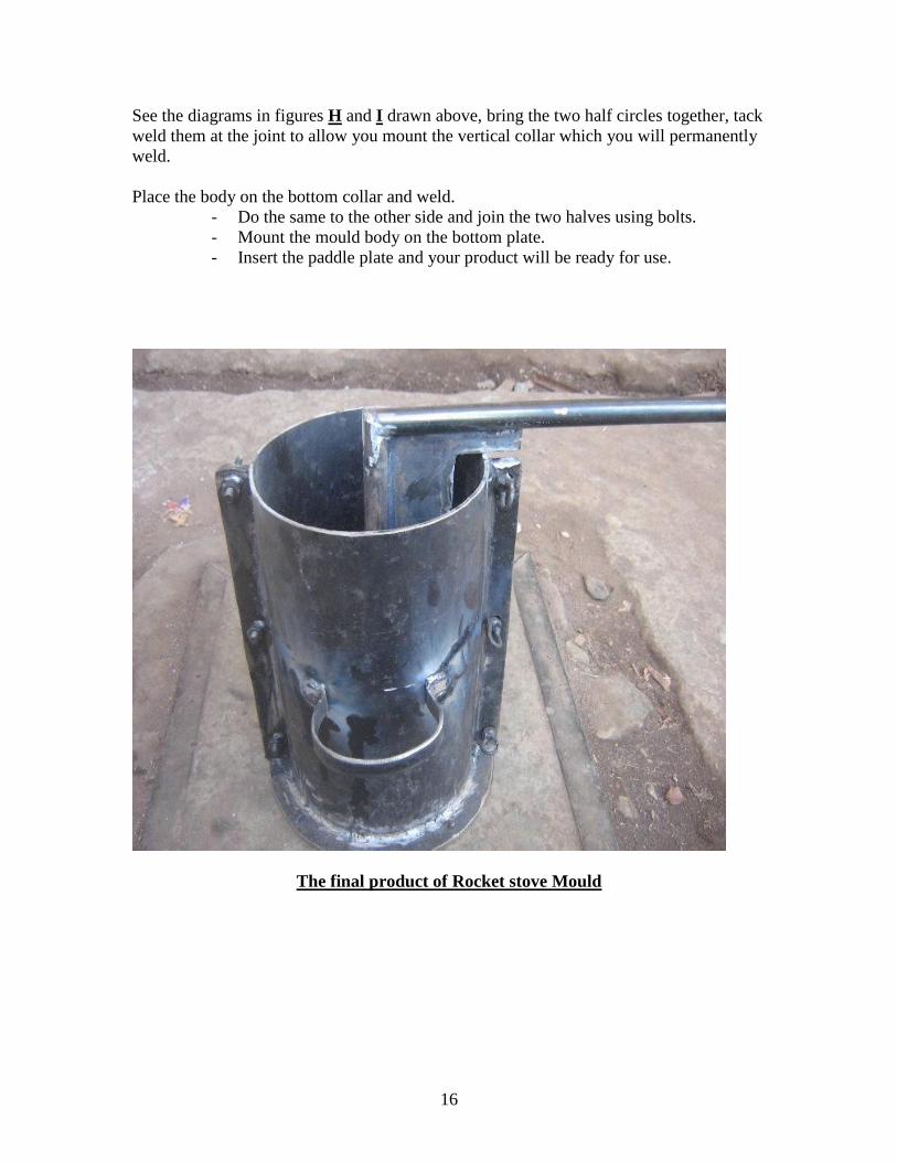
See the diagrams in figures H and I drawn above, bring the two half circles together, tack
weld them at the joint to allow you mount the vertical collar which you will permanently
weld.
Place the body on the bottom collar and weld.
- Do the same to the other side and join the two halves using bolts.
- Mount the mould body on the bottom plate.
- Insert the paddle plate and your product will be ready for use.
The final product of Rocket stove Mould
17
JIKO KISASA MOULD.
JIKO KISASA MOULD TEMPLETE
Jiko kisasa template mould was the most technically complicated part of this training.
The theory part of this process also took a little longer because it had a lot of explanations
due it its unique technicality. The participants had difficulties in understanding the
correct measurements and this forced the facilitators to extend the facilitation longer than
expected, this part covered the whole morning session.
The jiko kisasa mould comprise of the following parts:
1) MOULD BODY
2) BOTTOM PLATE
3) RING COLLAR
4) PADDLE WEB
5) CENTER SHAFT
6) LOCATION PINS
.
PROCESS.
PRODUCE ATEMPLATE THAT WILL MAKE YOUR WORK EASIER AND
ACCURATE.
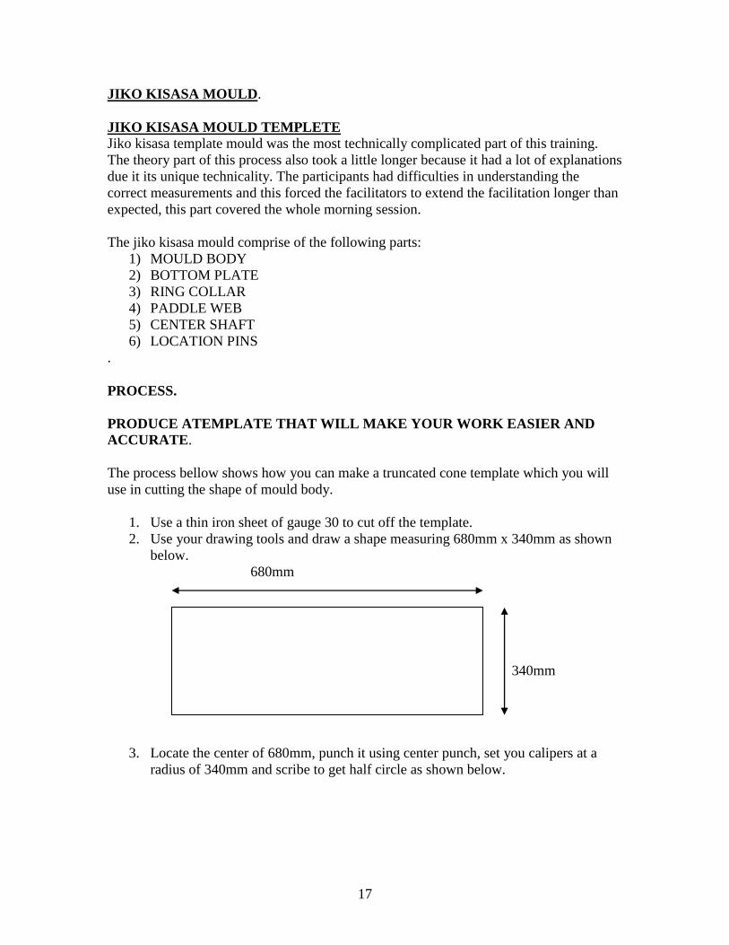
The process bellow shows how you can make a truncated cone template which you will
use in cutting the shape of mould body.
1. Use a thin iron sheet of gauge 30 to cut off the template.
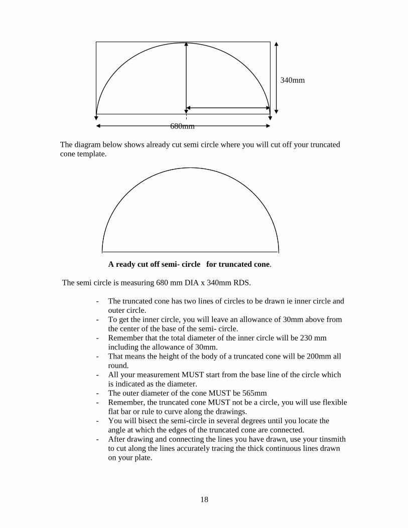
2. Use your drawing tools and draw a shape measuring 680mm x 340mm as shown
below.
680mm
340mm
3. Locate the center of 680mm, punch it using center punch, set you calipers at a
radius of 340mm and scribe to get half circle as shown below.
18
340mm
680mm
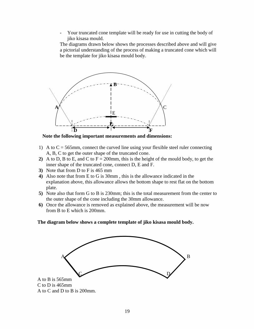
The diagram below shows already cut semi circle where you will cut off your truncated
cone template.
A ready cut off semi- circle for truncated cone.
The semi circle is measuring 680 mm DIA x 340mm RDS.
- The truncated cone has two lines of circles to be drawn ie inner circle and
outer circle.
- To get the inner circle, you will leave an allowance of 30mm above from
the center of the base of the semi- circle.
- Remember that the total diameter of the inner circle will be 230 mm
including the allowance of 30mm.
- That means the height of the body of a truncated cone will be 200mm all
round.
- All your measurement MUST start from the base line of the circle which
is indicated as the diameter.
- The outer diameter of the cone MUST be 565mm
- Remember, the truncated cone MUST not be a circle, you will use flexible
flat bar or rule to curve along the drawings.
- You will bisect the semi-circle in several degrees until you locate the
angle at which the edges of the truncated cone are connected.
- After drawing and connecting the lines you have drawn, use your tinsmith
to cut along the lines accurately tracing the thick continuous lines drawn
on your plate.
19
- Your truncated cone template will be ready for use in cutting the body of
jiko kisasa mould.
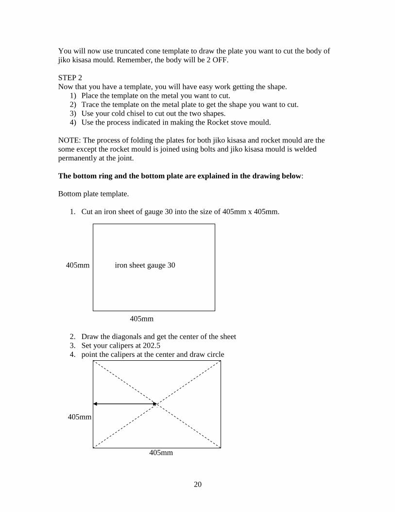
The diagrams drawn below shows the processes described above and will give
a pictorial understanding of the process of making a truncated cone which will
be the template for jiko kisasa mould body.
B
A C
E
G
D F
Note the following important measurements and dimensions:
1) A to C = 565mm, connect the curved line using your flexible steel ruler connecting
A, B, C to get the outer shape of the truncated cone.
2) A to D, B to E, and C to F = 200mm, this is the height of the mould body, to get the
inner shape of the truncated cone, connect D, E and F.
3) Note that from D to F is 465 mm
4) Also note that from E to G is 30mm , this is the allowance indicated in the
explanation above, this allowance allows the bottom shape to rest flat on the bottom
plate.
5) Note also that form G to B is 230mm; this is the total measurement from the center to
the outer shape of the cone including the 30mm allowance.
6) Once the allowance is removed as explained above, the measurement will be now
from B to E which is 200mm.
The diagram below shows a complete template of jiko kisasa mould body.
A B
C D
A to B is 565mm
C to D is 465mm
A to C and D to B is 200mm.
20
You will now use truncated cone template to draw the plate you want to cut the body of
jiko kisasa mould. Remember, the body will be 2 OFF.
STEP 2
Now that you have a template, you will have easy work getting the shape.
1) Place the template on the metal you want to cut.
2) Trace the template on the metal plate to get the shape you want to cut.
3) Use your cold chisel to cut out the two shapes.
4) Use the process indicated in making the Rocket stove mould.
NOTE: The process of folding the plates for both jiko kisasa and rocket mould are the
some except the rocket mould is joined using bolts and jiko kisasa mould is welded
permanently at the joint.
The bottom ring and the bottom plate are explained in the drawing below:
Bottom plate template.
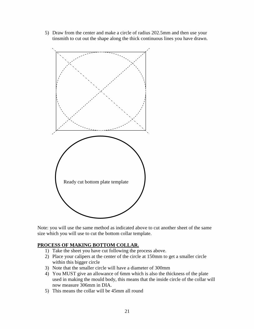
1. Cut an iron sheet of gauge 30 into the size of 405mm x 405mm.
405mm iron sheet gauge 30
405mm
2. Draw the diagonals and get the center of the sheet
3. Set your calipers at 202.5
4. point the calipers at the center and draw circle
Getting diagonal
202.5mm
405mm
405mm
21
5) Draw from the center and make a circle of radius 202.5mm and then use your
tinsmith to cut out the shape along the thick continuous lines you have drawn.
Drawing bottom plate
Ready cut bottom plate template
Note: you will use the same method as indicated above to cut another sheet of the same
size which you will use to cut the bottom collar template.
PROCESS OF MAKING BOTTOM COLLAR.
1) Take the sheet you have cut following the process above.
2) Place your calipers at the center of the circle at 150mm to get a smaller circle
within this bigger circle
3) Note that the smaller circle will have a diameter of 300mm
4) You MUST give an allowance of 6mm which is also the thickness of the plate
used in making the mould body, this means that the inside circle of the collar will
now measure 306mm in DIA.
5) This means the collar will be 45mm all round
22
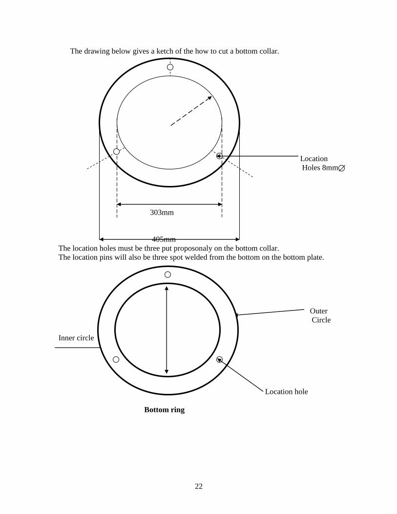
The drawing below gives a ketch of the how to cut a bottom collar.
Location
Holes 8mm
303mm
405mm
The location holes must be three put proposonaly on the bottom collar.
The location pins will also be three spot welded from the bottom on the bottom plate.
Outer
Circle
Inner circle
306mm
Location hole
Bottom ring
23
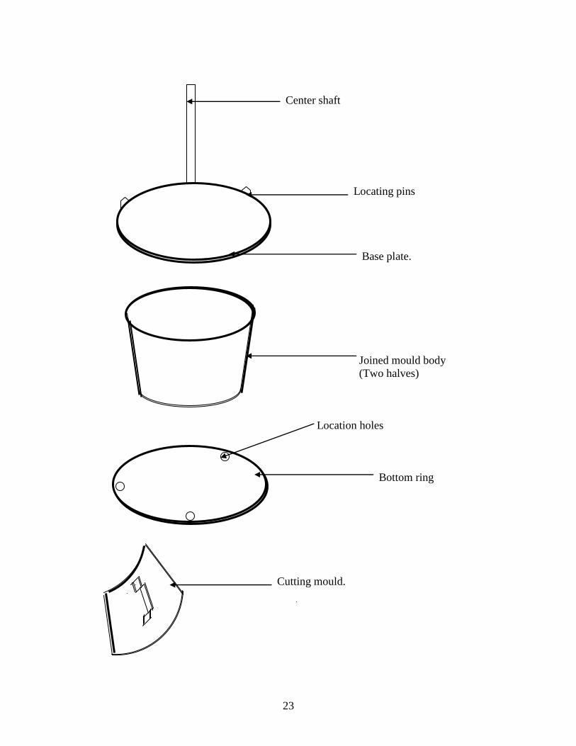
Center shaft
Locating pins
Base plate.
Joined mould body
(Two halves)
Location holes
Bottom ring
Cutting mould.
24
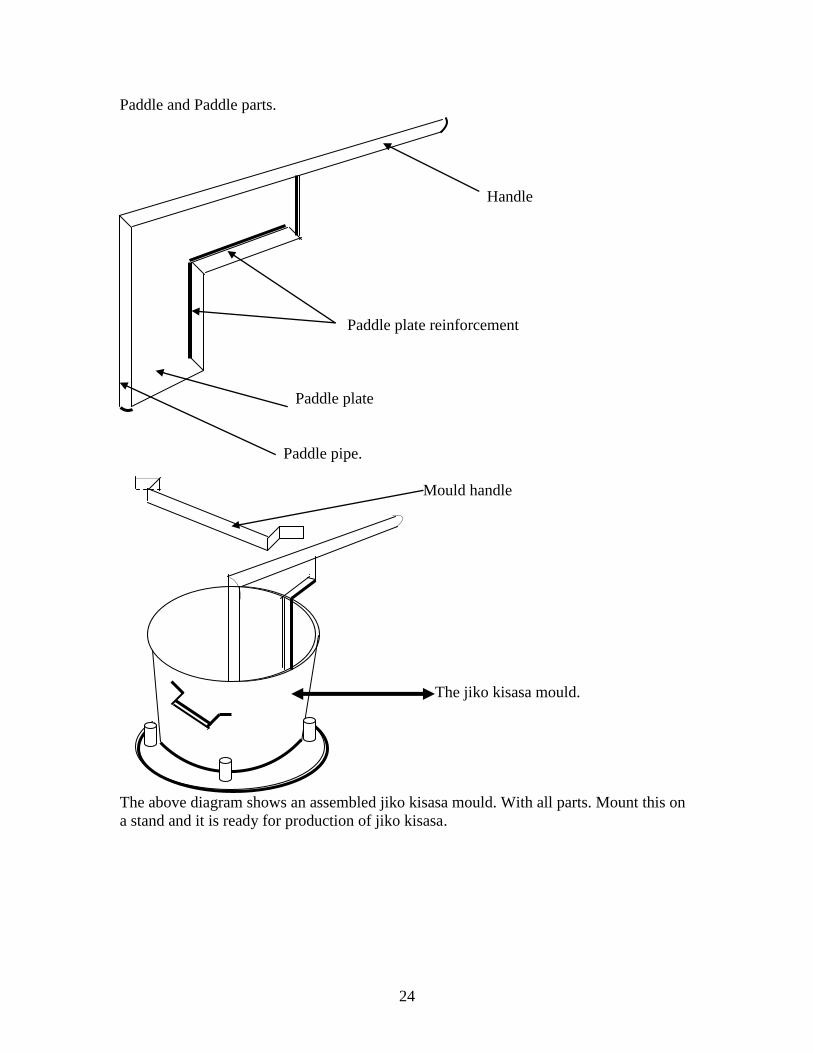
Paddle and Paddle parts.
Handle
Paddle plate reinforcement
Paddle plate
Paddle pipe.
Mould handle
The jiko kisasa mould.
The above diagram shows an assembled jiko kisasa mould. With all parts. Mount this on
a stand and it is ready for production of jiko kisasa.
25
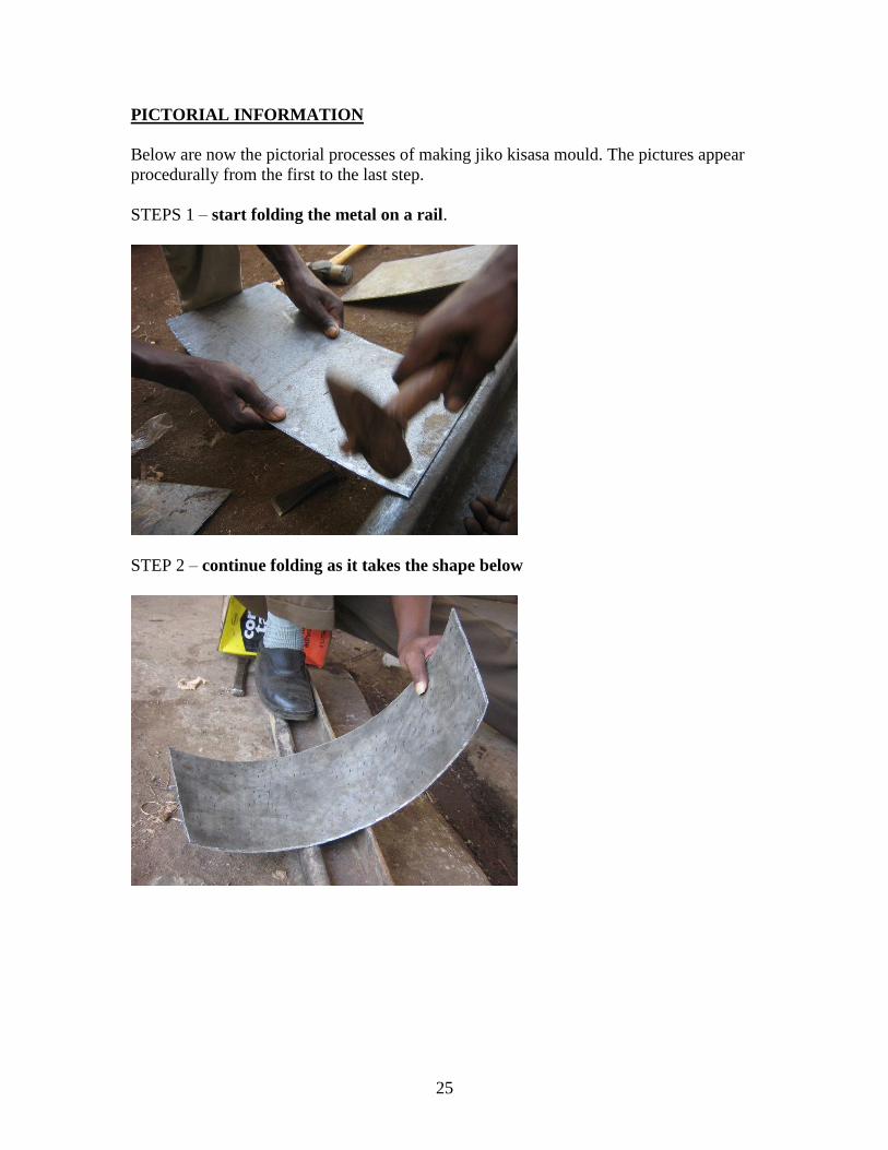
PICTORIAL INFORMATION
Below are now the pictorial processes of making jiko kisasa mould. The pictures appear
procedurally from the first to the last step.
STEPS 1 – start folding the metal on a rail.
STEP 2 – continue folding as it takes the shape below
26
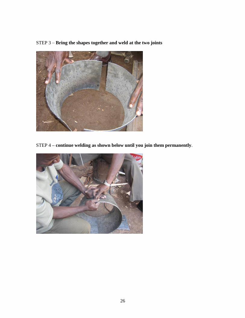
STEP 3 – Bring the shapes together and weld at the two joints
STEP 4 – continue welding as shown below until you join them permanently.
27
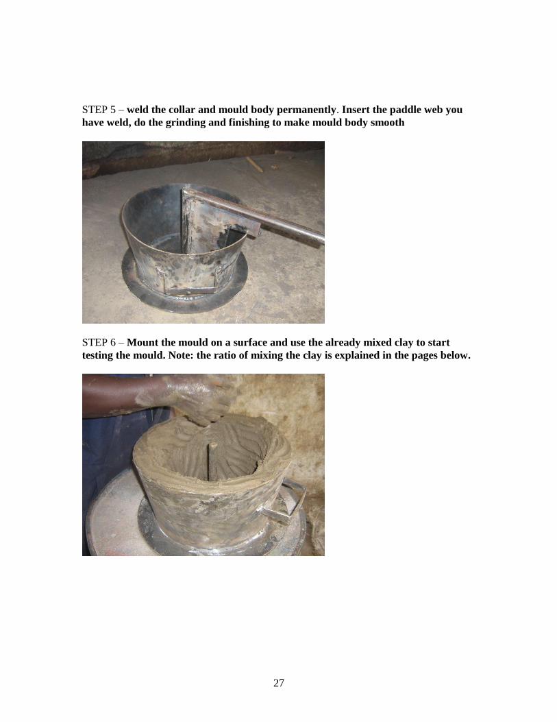
STEP 5 – weld the collar and mould body permanently. Insert the paddle web you
have weld, do the grinding and finishing to make mould body smooth
STEP 6 – Mount the mould on a surface and use the already mixed clay to start
testing the mould. Note: the ratio of mixing the clay is explained in the pages below.
28
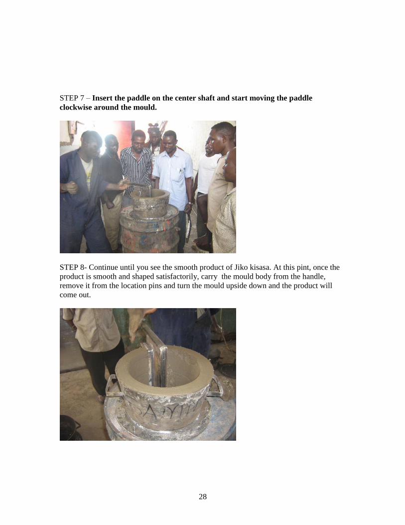
STEP 7 – Insert the paddle on the center shaft and start moving the paddle
clockwise around the mould.
STEP 8- Continue until you see the smooth product of Jiko kisasa. At this pint, once the
product is smooth and shaped satisfactorily, carry the mould body from the handle,
remove it from the location pins and turn the mould upside down and the product will
come out.
29
MAKING CLAY.
Important notes:
Items and materials needed for mixing .clay.
Materials:
1) pottery clay
2) Sand
3) Ant hill
4) Water
5) Ash
6) polythine paper
Process:
1) Look for a quality pottery clay
2) Use fine sand
3) Fetch for a wet ant hill clay and
4) Get enough ash.
Ratio;
1) Take 3 gallons of black clay
2) Half gallon of sand
3) Half gallon of ant hill clay
4) Mix the above materials evenly and any particle.
5) Sprinkle the mixture with 1 gallon of water.
6) Cover the mixture with a polythine paper for 21 days
7) After 21 days, do the soaking using apiece of wood or your legs
8) Do thorough wedging and remove any particles from the clay.
9) The clay is ready for use.
Note: before you start the process of putting the clay of the mould, make sure you
sprinkle enough Ash inside the mould; this will ease the removal of the products from the
mould.
Alternatively, you can also buy the ready made mixture of clay from various potters who
are selling the ready made clay. Remember, the quality of the clay will different
depending on the region where you buy it from.
30
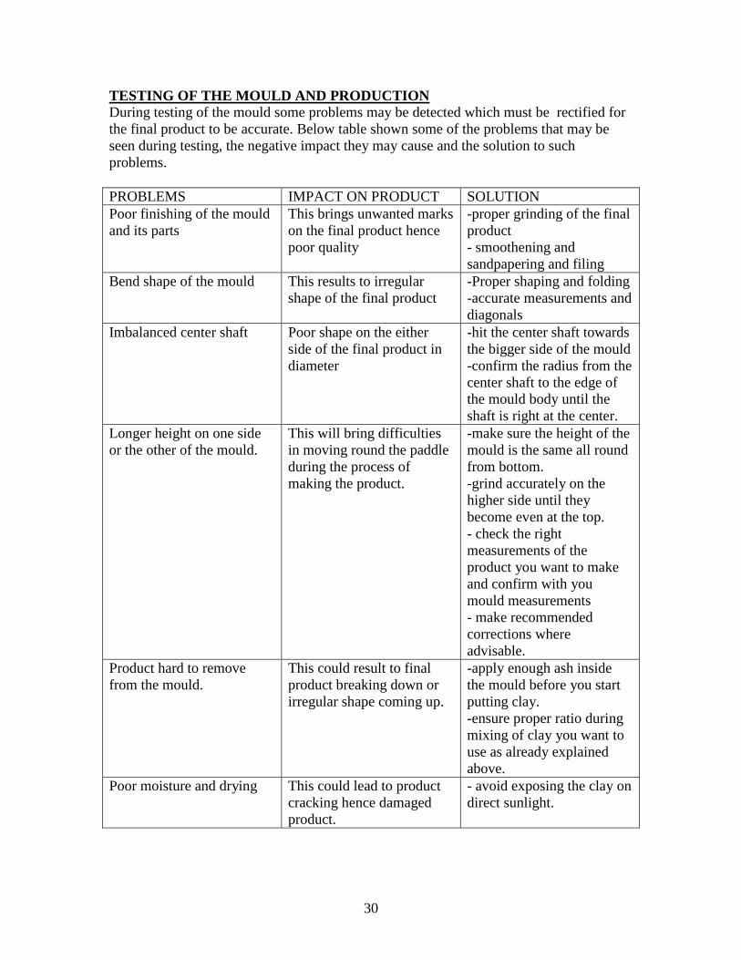
TESTING OF THE MOULD AND PRODUCTION
During testing of the mould some problems may be detected which must be rectified for
the final product to be accurate. Below table shown some of the problems that may be
seen during testing, the negative impact they may cause and the solution to such
problems.
PROBLEMS IMPACT ON PRODUCT SOLUTION
Poor finishing of the mould
and its parts
This brings unwanted marks
on the final product hence
poor quality
-proper grinding of the final
product
- smoothening and
sandpapering and filing
Bend shape of the mould This results to irregular
shape of the final product
-Proper shaping and folding
-accurate measurements and
diagonals
Imbalanced center shaft Poor shape on the either
side of the final product in
diameter
-hit the center shaft towards
the bigger side of the mould
-confirm the radius from the
center shaft to the edge of
the mould body until the
shaft is right at the center.
Longer height on one side
or the other of the mould.
This will bring difficulties
in moving round the paddle
during the process of
making the product.
-make sure the height of the
mould is the same all round
from bottom.
-grind accurately on the
higher side until they
become even at the top.
- check the right
measurements of the
product you want to make
and confirm with you
mould measurements
- make recommended
corrections where
advisable.
Product hard to remove
from the mould.
This could result to final
product breaking down or
irregular shape coming up.
-apply enough ash inside
the mould before you start
putting clay.
-ensure proper ratio during
mixing of clay you want to
use as already explained
above.
Poor moisture and drying This could lead to product
cracking hence damaged
product.
- avoid exposing the clay on
direct sunlight.
31
In your final product make sure that the corrections are done to help you come up with a
quality product according to specifications. After you are satisfied that the final product is
good, apply the below final touches;
1) Use the Amerry cloth to sandpaper your final product.
2) Use a soft piece of cloth to wipe out any dust on the mould body.
3) Use a painting brush to apply a quality oil paint on your product.
4) Leave it to dry where there is enough moisture.
5) Once you are satisfied that your product has dried completely, it is ready for use
and can be used in mould production.
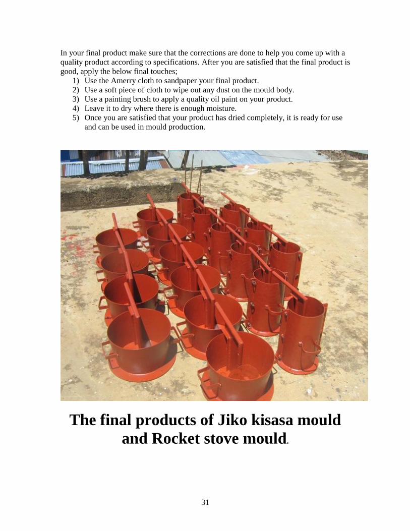
The final products of Jiko kisasa mould
and Rocket stove mould.
32
The collection, documentation, technical drawings, pictorial information and final
writing of this report was done by;
Mr. Okanga George
Practical training was done by;
Mr. Ochere Joseph Caleb, assisted by Mr. Okanga George
Proofreading of this report was done by;
Mr. Okanga George
Mr. Ochere Joseph Caleb
CONTACTS;
GEORGE OKANGA
P.O.BOX 7060
KISUMU- 40100
TEL; 0721 41 48 26
0733 95 90 31
E-MAIL; [email protected] / [email protected]
JOSEPH CALEB OCHERE
P.O.BOX 196031
KISUMU
TEL; 0726 65 95 62
E-MAIL; [email protected]