Embed Size (px)
Citation preview
© 2017 Nokia1
GSM-R Network Dimensioning, Design & Optimization
• Giorgio Ronchi, NOKIA
© 2017 Nokia2
GSM-R Network Planning & Optimization Agenda
• Network Dimensioning – Traffic Model
• Network Design
• Tunnel Coverage
• Planning for High-Speed Lines
• Tuning, Acceptance & Optimization.
• References.
© 2017 Nokia3
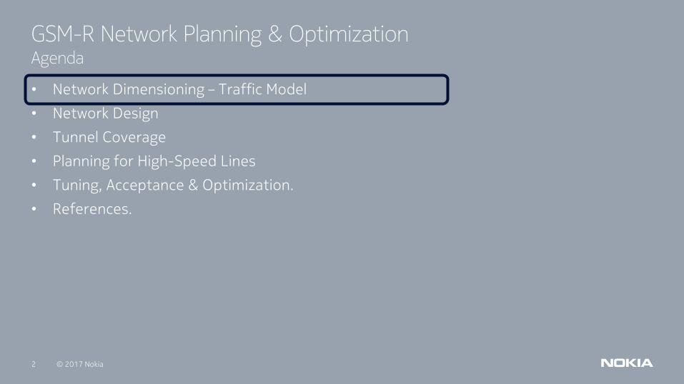
GSM-R Dimensioning
•GSM-R Applications: ETCS tracks /VGCS.
•Subscribers: workers of the railway transportation company.
•Smaller traffic, however some connections (i.e. ETCS) need to be permanent.
•Limited number of frequencies available.
•Traffic is concentrated in certain areas i.e. in railway platforms and shunting platforms.
© 2017 Nokia4
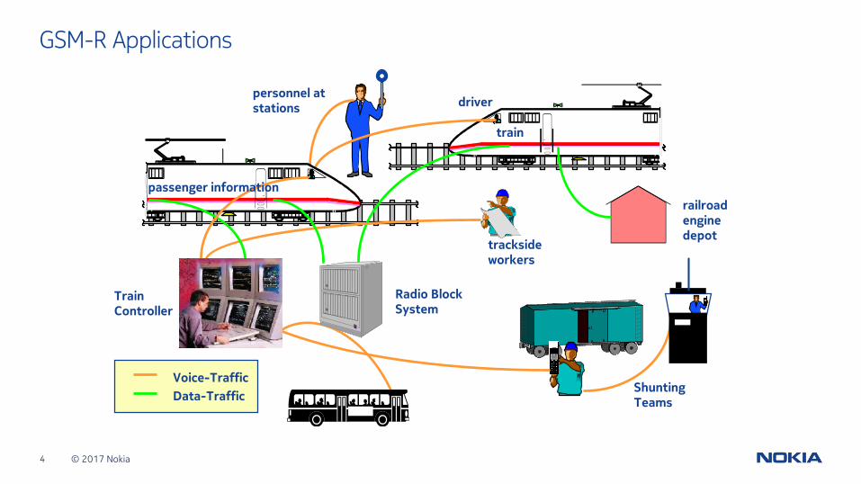
GSM-R Applications
Shunting Teams
trackside workers
Train Controller
personnel at stations
Radio Block System
railroadenginedepot
driver
train
Voice-Traffic
Data-Traffic
trainpassenger information
© 2017 Nokia5
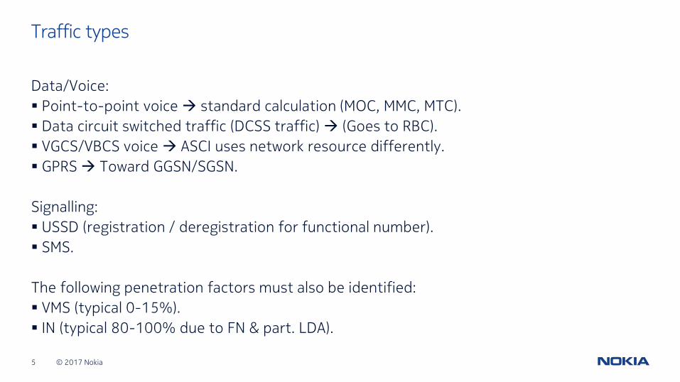
Traffic types
Data/Voice:
▪ Point-to-point voice standard calculation (MOC, MMC, MTC).
▪ Data circuit switched traffic (DCSS traffic) (Goes to RBC).
▪ VGCS/VBCS voice ASCI uses network resource differently.
▪ GPRS Toward GGSN/SGSN.
Signalling:
▪ USSD (registration / deregistration for functional number).
▪ SMS.
The following penetration factors must also be identified:
▪ VMS (typical 0-15%).
▪ IN (typical 80-100% due to FN & part. LDA).
© 2017 Nokia6
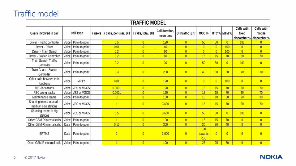
Traffic model
Users involved in call # users # calls, per user, BH # calls, total, BHCall duration,
mean timeBH traffic [Erl] MOC % MTC % MTM %
Calls with
fixed
dispatcher %
Calls with
mobile
dispatcher %
Driver - Traffic controller Voice Point-to-point 0.5 0 120 0 50 50 0 100 0
Driver - Driver Voice Point-to-point 0.01 0 60 0 0 0 100 0 0
Driver - Train Guard Voice Point-to-point 0.2 0 60 0 0 0 100 0 0
Driver - Station Controller Voice Point-to-point 0.2 0 60 0 15 15 70 30 70
Train Guard - Traffic
ControllerVoice Point-to-point 0.2 0 30 0 50 50 0 100 0
Train Guard - Station
ControllerVoice Point-to-point 0.3 0 200 0 40 30 30 70 30
Other calls between train
functionsVoice MPTY 0.01 0 120 0 0 0 100 0 0
REC in stations Voice VBS or VGCS 0.0001 0 120 0 15 15 70 30 70
REC along tracks Voice VBS or VGCS 0.0001 0 120 0 15 15 70 30 70
Maintenance teams Voice Point-to-point 3 0 180 0 10 10 80 20 30
Shunting teams in small -
medium size stationsVoice VBS or VGCS 1 0 3,600 0 15 15 70 30 70
Shunting teams in big
stationsVoice VBS or VGCS 0.5 0 3,600 0 50 50 0 100 0
Other GSM-R internal calls Voice Point-to-point 1 0 100 0 15 15 70 0 0
Other GSM-R internal calls Data Point-to-point 0.15 0 300 0 30 30 40 0 0
ERTMS Data Point-to-point 1 0 3,600 0
100
towards
RBC
0 0 0 0
Other GSM-R external calls Voice Point-to-point 1 0 100 0 25 25 50 0 0
TRAFFIC MODEL
Call Type
© 2017 Nokia7
GSM-R Network Planning & Optimization Agenda
• Network Dimensioning – Traffic Model
• Network Design
• Tunnel Coverage
• Planning for High-Speed Lines
• Tuning, Acceptance & Optimization.
• References.
© 2017 Nokia8
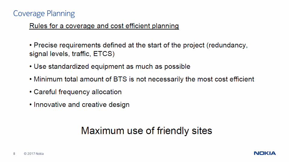
Coverage Planning
© 2017 Nokia9
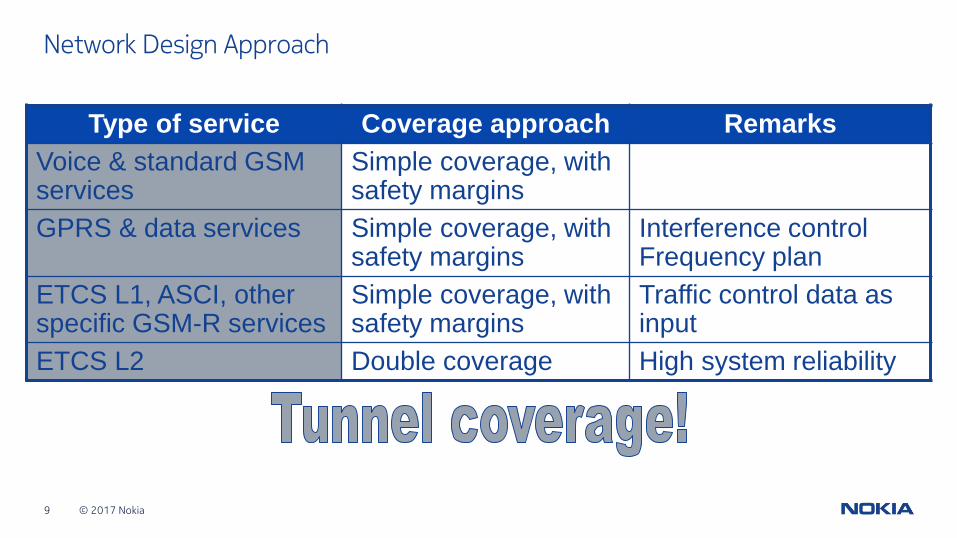
Network Design Approach
Type of service Coverage approach Remarks
Voice & standard GSM services
Simple coverage, with safety margins
GPRS & data services Simple coverage, with safety margins
Interference control Frequency plan
ETCS L1, ASCI, other specific GSM-R services
Simple coverage, with safety margins
Traffic control data as input
ETCS L2 Double coverage High system reliability
© 2017 Nokia10
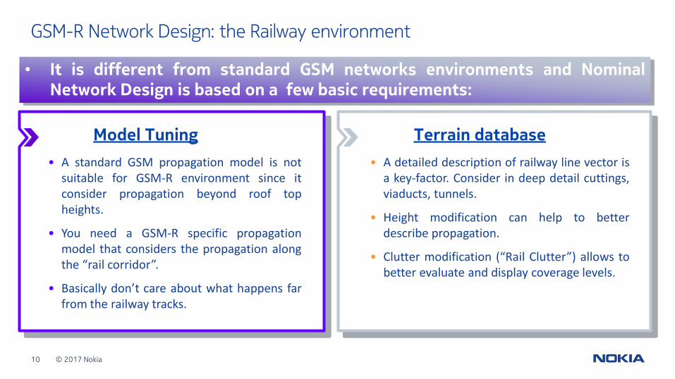
GSM-R Network Design: the Railway environment
Terrain database
• A detailed description of railway line vector isa key-factor. Consider in deep detail cuttings,viaducts, tunnels.
• Height modification can help to betterdescribe propagation.
• Clutter modification (“Rail Clutter”) allows tobetter evaluate and display coverage levels.
• It is different from standard GSM networks environments and NominalNetwork Design is based on a few basic requirements:
Model Tuning
• A standard GSM propagation model is notsuitable for GSM-R environment since itconsider propagation beyond roof topheights.
• You need a GSM-R specific propagationmodel that considers the propagation alongthe “rail corridor”.
• Basically don’t care about what happens farfrom the railway tracks.
© 2017 Nokia11
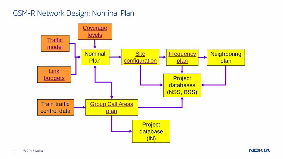
GSM-R Network Design: Nominal Plan
Nominal
Plan
Traffic
model
Coverage
levels
Link
budgets
Site
configuration
Frequency
plan
Neighboring
plan
Project
databases
(NSS, BSS)
Group Call Areas
plan
Train traffic
control data
Project
database
(IN)
© 2017 Nokia12
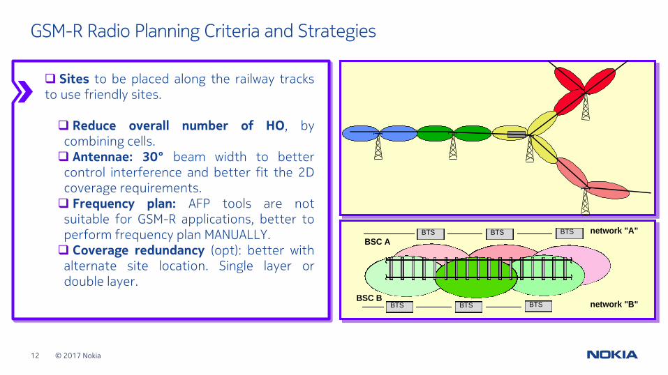
GSM-R Radio Planning Criteria and Strategies
network "A"
network "B"BTS BTS
BTS BTS BTS
BTS
BSC A
BSC B
Sites to be placed along the railway tracksto use friendly sites.
Reduce overall number of HO, bycombining cells. Antennae: 30° beam width to bettercontrol interference and better fit the 2Dcoverage requirements. Frequency plan: AFP tools are notsuitable for GSM-R applications, better toperform frequency plan MANUALLY. Coverage redundancy (opt): better withalternate site location. Single layer ordouble layer.
© 2017 Nokia13
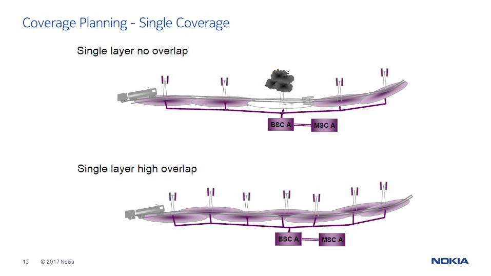
Coverage Planning - Single Coverage
© 2017 Nokia14
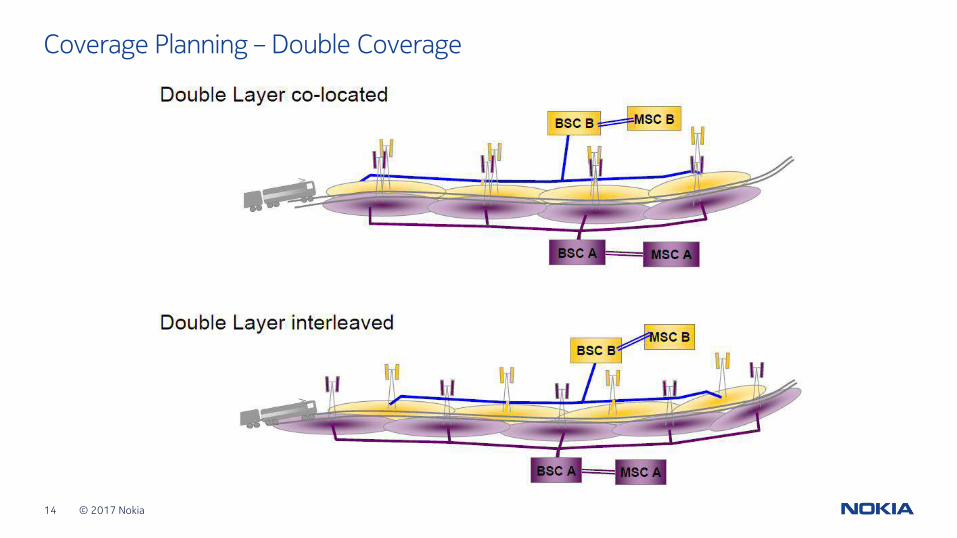
Coverage Planning – Double Coverage
© 2017 Nokia15
GSM-R Network Planning & Optimization Agenda
• Network Dimensioning – Traffic Model
• Network Design
• Tunnel Coverage
• Planning for High-Speed Lines
• Tuning, Acceptance & Optimization.
• References.
© 2017 Nokia16
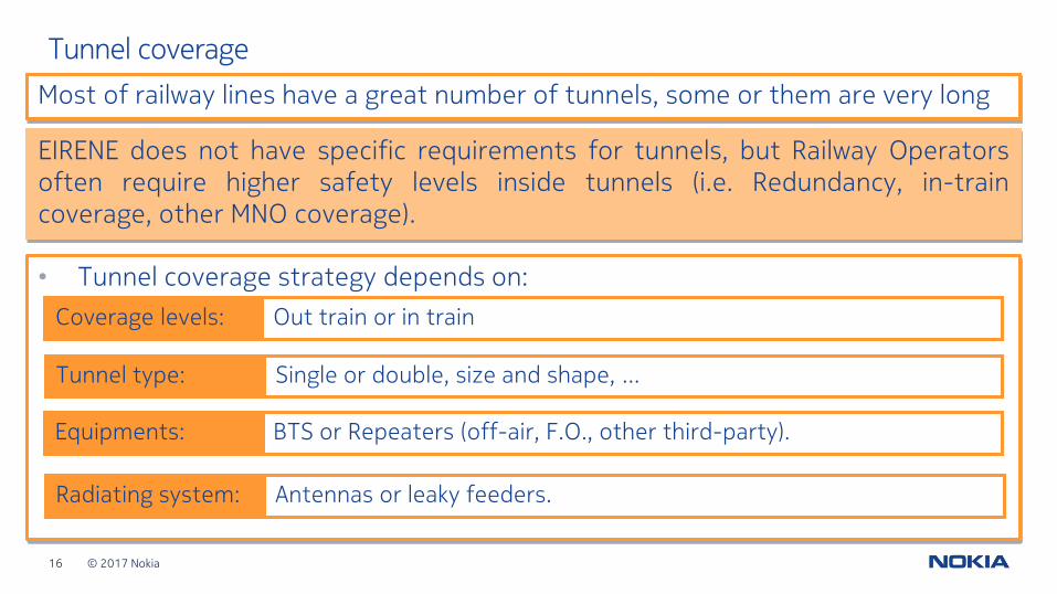
Tunnel coverage
• Tunnel coverage strategy depends on:
Most of railway lines have a great number of tunnels, some or them are very long
EIRENE does not have specific requirements for tunnels, but Railway Operatorsoften require higher safety levels inside tunnels (i.e. Redundancy, in-traincoverage, other MNO coverage).
Out train or in trainCoverage levels:
Single or double, size and shape, …Tunnel type:
BTS or Repeaters (off-air, F.O., other third-party).Equipments:
Radiating system: Antennas or leaky feeders.
© 2017 Nokia17
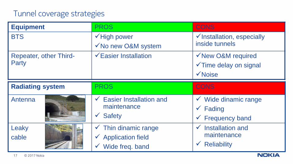
Tunnel coverage strategies
Equipment PROS CONS
BTS ✓High power
✓No new O&M system
✓Installation, especially inside tunnels
Repeater, other Third-Party
✓Easier Installation ✓New O&M required
✓Time delay on signal
✓Noise
Radiating system PROS CONS
Antenna ✓ Easier Installation and maintenance
✓ Safety
✓ Wide dinamic range
✓ Fading
✓ Frequency band
Leaky
cable
✓ Thin dinamic range
✓ Application field
✓ Wide freq. band
✓ Installation and maintenance
✓ Reliability
© 2017 Nokia18
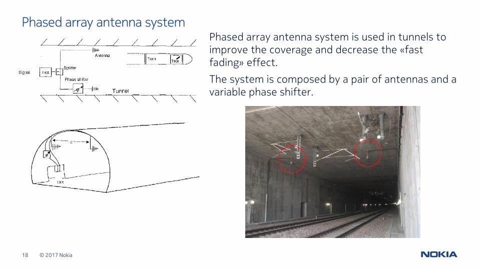
Phased array antenna systemPhased array antenna system is used in tunnels to improve the coverage and decrease the «fast fading» effect.
The system is composed by a pair of antennas and a variable phase shifter.
© 2017 Nokia19
GSM-R Network Planning & Optimization Agenda
• Network Dimensioning – Traffic Model
• Network Design
• Tunnel Coverage
• Planning for High-Speed Lines
• Tuning, Acceptance & Optimization.
• References.
© 2017 Nokia20
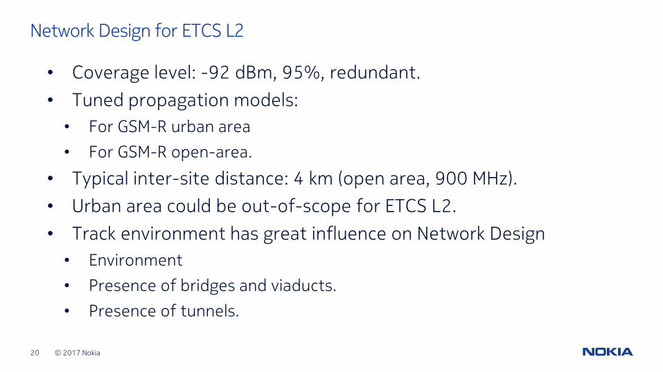
Network Design for ETCS L2
• Coverage level: -92 dBm, 95%, redundant.
• Tuned propagation models:
• For GSM-R urban area
• For GSM-R open-area.
• Typical inter-site distance: 4 km (open area, 900 MHz).
• Urban area could be out-of-scope for ETCS L2.
• Track environment has great influence on Network Design
• Environment
• Presence of bridges and viaducts.
• Presence of tunnels.
© 2017 Nokia21
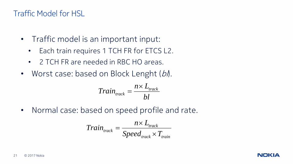
Traffic Model for HSL
• Traffic model is an important input:
• Each train requires 1 TCH FR for ETCS L2.
• 2 TCH FR are needed in RBC HO areas.
• Worst case: based on Block Lenght (bl).
• Normal case: based on speed profile and rate.
bl
LnTrain track
track
traintrack
tracktrack
TSpeed
LnTrain
© 2017 Nokia22
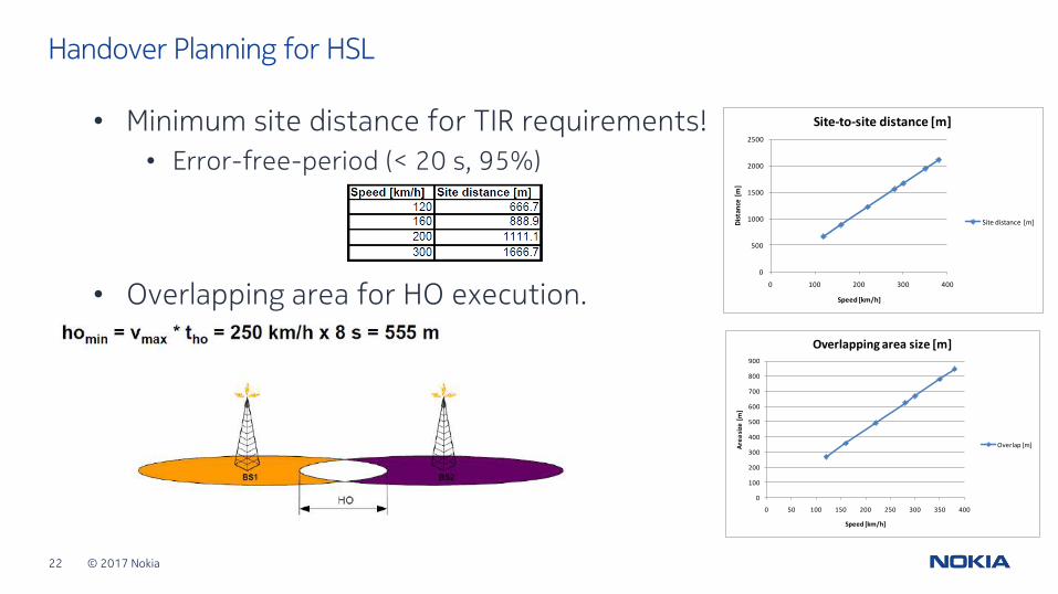
Handover Planning for HSL
• Minimum site distance for TIR requirements!
• Error-free-period (< 20 s, 95%)
• Overlapping area for HO execution.0
500
1000
1500
2000
2500
0 100 200 300 400
Dis
tan
ce [
m]
Speed [km/h]
Site-to-site distance [m]
Site distance [m]
0
100
200
300
400
500
600
700
800
900
0 50 100 150 200 250 300 350 400
Are
a si
ze [
m]
Speed [km/h]
Overlapping area size [m]
Overlap [m]
© 2017 Nokia23
GSM-R Network Planning & Optimization Agenda
• Network Dimensioning – Traffic Model
• Network Design
• Tunnel Coverage
• Planning for High-Speed Lines
• Tuning, Acceptance & Optimization.
• References.
© 2017 Nokia24
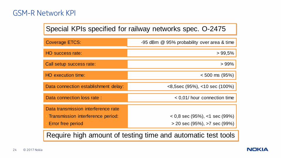
GSM-R Network KPI
Special KPIs specified for railway networks spec. O-2475
-95 dBm @ 95% probability over area & timeCoverage ETCS:
> 99,5%HO success rate:
> 99%Call setup success rate:
< 500 ms (95%)HO execution time:
<8,5sec (95%), <10 sec (100%)Data connection establishment delay:
< 0,01/ hour connection timeData connection loss rate :
< 0,8 sec (95%), <1 sec (99%)
> 20 sec (95%), >7 sec (99%)
Data transmission interference rate
• Transmission interference period:
• Error free period
Require high amount of testing time and automatic test tools
© 2017 Nokia25
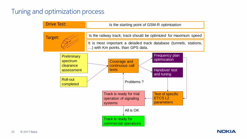
Tuning and optimization process
Drive Test: Is the starting point of GSM-R optimization
Target: Is the railway track; track should be optimized for maximum speed
It is most important a detailed track database (tunnels, stations,
…) with Km points, than GPS data.
Roll-out
completed
Preliminary
spectrum
clearance
assessment
Coverage and continuous call tests Handover test
and tuning
Frequency plan optimization
Test of specific ETCS L2 parameters
Track is ready for trial
operation of signaling
systems
Track is ready for
commercial operations
All is OK
Problems ?
© 2017 Nokia26 <Document ID: change ID in footer or remove> <Change information classification in footer>
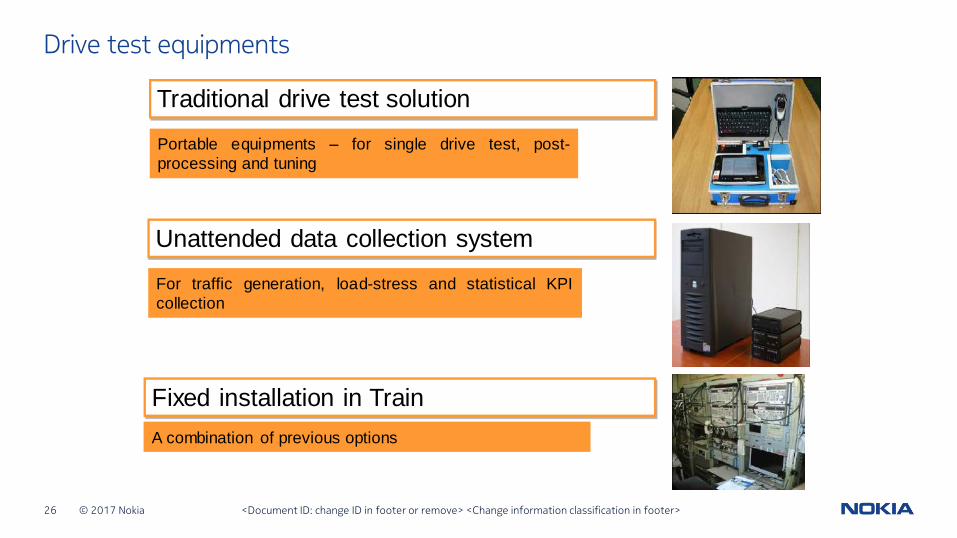
Drive test equipments
Traditional drive test solution
Fixed installation in Train
Portable equipments – for single drive test, post-
processing and tuning
A combination of previous options
Unattended data collection system
For traffic generation, load-stress and statistical KPI
collection
© 2017 Nokia27
Optimization process
• Tuning and optimazition is a critical phase during the realization of a GSM-R network.
• A big amount of drive-test is needed to collect all the necessaryinformations.
• Step 0 is the preliminar assessment of the environment, for the detectionof external interferences.
• Step 1 is the coverage optimization with adjustements of antenna azimutsand tilts.
• Step 2 is the optimization of network performances with the setting of optimized database parameters for each cell.
• At the end of Step 2 network is fully ready for commercial operations.
© 2017 Nokia28
• During coverage assessment phase, some coverage problem COULD be detected and MUST be solved before proceeding.
• Possible coverage problems are:
1. Lack of coverage (holes, fast-field-drop).
2. Far cell camping.
• Possible solutions are:
1. Check site installation, correct azimut.
2. Add mechanical or electical downtilt.
Coverage optimization
© 2017 Nokia29
• The most critical performances are related to ETCS services (CSD calls).
• Typical problems are the violations of TTI or TREC.
• Possible causes are of 2 types:
1. For both parameters: HO break time too long or interference.
2. For TREC violation, HO procedures: distance between HO too short or ping-pong/intracell HO.
Performances optimization
© 2017 Nokia30
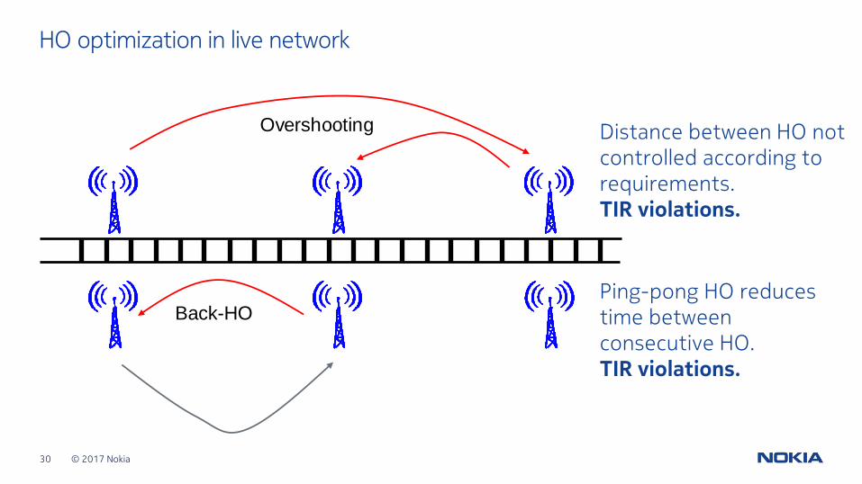
HO optimization in live network
Distance between HO not controlled according to requirements.TIR violations.
Ping-pong HO reduces time between consecutive HO.TIR violations.
Overshooting
Back-HO
© 2017 Nokia31
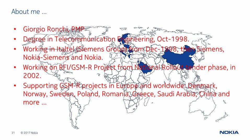
• Giorgio Ronchi, PMP
• Degree in Telecommunication Engineering, Oct-1998.
• Working in Italtel (Siemens Group) from Dec-1998, then Siemens, Nokia-Siemens and Nokia.
• Working on RFI/GSM-R Project from National Rollout tender phase, in 2002.
• Supporting GSM-R projects in Europe and worldwide: Denmark, Norway, Sweden, Poland, Romania, Greece, Saudi Arabia, China and more …
About me …

© 2017 Nokia33 <Document ID: change ID in footer or remove> <Change information classification in footer>
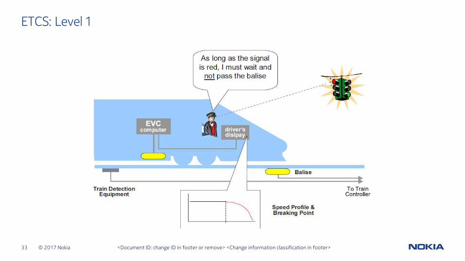
ETCS: Level 1
© 2017 Nokia34 <Document ID: change ID in footer or remove> <Change information classification in footer>
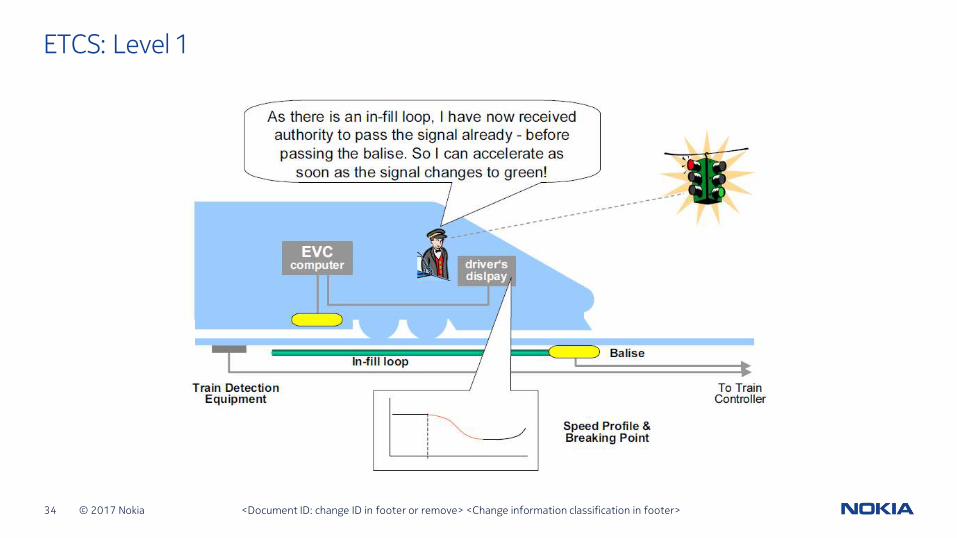
ETCS: Level 1
© 2017 Nokia35 <Document ID: change ID in footer or remove> <Change information classification in footer>
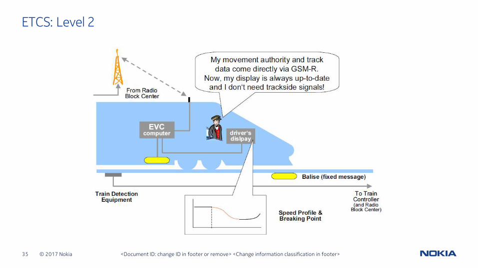
ETCS: Level 2
© 2017 Nokia36 <Document ID: change ID in footer or remove> <Change information classification in footer>
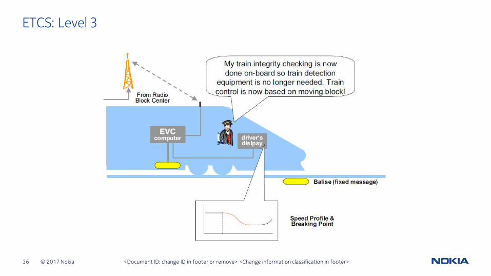
ETCS: Level 3


![Performance Evaluation of Integrated Voice/Data Services ... · radio resource dimensioning. For voice traffic over GSM, Erlang model [1] is still the main tool for resource dimensioning](https://img.pdfslide.us/doc/110x75/5b42ef767f8b9a85708b76cb/performance-evaluation-of-integrated-voicedata-services-radio-resource.jpg)