Embed Size (px)
Citation preview
Version HistoryVersion 1.0 (initial release )- October 2018
GSM Plug-in Installation GuideMAN-01-00478-1.01

Contents
Contents 2Disclaimers 3
Important Notice 3Emission Compliance 3
Support and Contact Information 5About This Guide 7Chapter 1: Installation Guidelines 8
Guidelines for installing a SIM Card 9If Using a Non-SolarEdge SIM Card 9
Chapter 2: System Compatibility Check and Upgrade 12Software Requirements 12
Chapter 3: GSM Plug-in and Antenna Installation 13Package Contents 13Clipping the Antenna to the inverter 13Connecting the Antenna to a Vertical Surface using a Bracket 16Installing the Plug-In in the Inverter 16
Chapter 4: Configuring GSM Communication 19Configuring the Inverter 19Verifying the Connection and Viewing Communication Status 23Viewing Error Messages and Troubleshooting 25
The Inverter is not Starting Up 25Plug-in LED Indications 28
Contents
GSM Plug-in Installation GuideMAN-01-00478-1.02
Technical Specifications .................................................................... 29
Disclaimers
DisclaimersImportant NoticeCopyright © SolarEdge Inc. All rights reserved.No part of this document may be reproduced, stored in a retrieval system or transmitted, in any form or by any means, electronic, mechanical, photographic, magnetic or otherwise, without the prior written permission of SolarEdge Inc.The material furnished in this document is believed to be accurate and reliable. However, SolarEdge assumes no responsibility for the use of this material. SolarEdge reserves the right to make changes to the material at any time and without notice. You may refer to the SolarEdge web site (www.solaredge.com) for the most updated version.All company and brand products and service names are trademarks or registered trademarks of their respective holders.Patent marking notice: see http://www.solaredge.com/patent The general terms and conditions of delivery of SolarEdge shall apply.The content of these documents is continually reviewed and amended, where necessary. However, discrepancies cannot be excluded. No guarantee is made for the completeness of these documents.The images contained in this document are for illustrative purposes only and may vary depending on product models.
Emission ComplianceThis equipment has been tested and found to comply with the limits applied by the local regulations. These limits are designed to provide reasonable protection against harmful interference in a residential installation. This equipment generates, uses and can radiate radio frequency energy and, if not installed and used in accordance with the instructions, may cause harmful interference to radio communications. However, there is no guarantee that interference will not occur in a particular installation. If this
GSM Plug-in Installation GuideMAN-01-00478-1.03
equipment does cause harmful interference to radio or television reception, which can be determined by turning the equipment off and on, you are encouraged to try to correct the interference by one or more of the following measures:l Reorient or relocate the receiving antenna.l Increase the separation between the equipment and the receiver.l Connect the equipment into an outlet on a circuit different from that to
which the receiver is connected.l Consult the dealer or an experienced radio/TV technician for help.Changes or modifications not expressly approved by the party responsible for compliance may void the user’s authority to operate the equipment.
Disclaimers
GSM Plug-in Installation GuideMAN-01-00478-1.04
Support and Contact Information
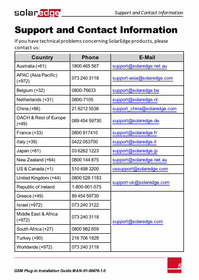
Support and Contact InformationIf you have technical problems concerning SolarEdge products, please contact us:
Country Phone E-MailAustralia (+61) 1800 465 567 [email protected]
APAC (Asia Pacific)(+972) 073 240 3118 [email protected]
Belgium (+32) 0800-76633 [email protected]
Netherlands (+31) 0800-7105 [email protected]
China (+86) 21 6212 5536 [email protected]
DACH & Rest of Europe (+49) 089 454 59730 [email protected]
France (+33) 0800 917410 [email protected]
Italy (+39) 0422 053700 [email protected]
Japan (+81) 03 6262 1223 [email protected]
New Zealand (+64) 0800 144 875 [email protected]
US & Canada (+1) 510 498 3200 [email protected]
United Kingdom (+44) 0800 028 1183 [email protected]
Republic of Ireland 1-800-901-575
Greece (+49) 89 454 59730
Israel (+972) 073 240 3122
Middle East & Africa (+972) 073 240 3118
South Africa (+27) 0800 982 659
Turkey (+90) 216 706 1929
Worldwide (+972) 073 240 3118
GSM Plug-in Installation GuideMAN-01-00478-1.05
Before contact, make sure to have the following information at hand: l Model and serial number of the product in question. l The error indicated on the Inverter SetApp mobile applicationscreen or
on the monitoring platform or by the LED, if there is such an indication. l System configuration information, including the type and number of
modules connected and the number and length of strings. l The communication method to the SolarEdge server, if the site is
connected. l The software version as appears in the ID status screen.
Support and Contact Information
GSM Plug-in Installation GuideMAN-01-00478-1.06
About This Guide
About This GuideSolarEdge offers the GSM communication option for connection of the SolarEdge inverter to the SolarEdge monitoring server. This guide assumes that the SolarEdge power harvesting system is already installed and commissioned. For additional information about how to install and commission the SolarEdge power harvesting system, refer to the relevant installation guide.This guide includes the following chapters: l Chapter 1: Installation Guidelines on page 8, provides guidelines for
installing the GSM Plug-in with or without data plan according to your system configuration.
l Chapter 2: Software Compatibility Check and Upgrade on page 1, describes the hardware and firmware requirements for using the GSM Plug-in.
l Chapter 3: Cellular GSM Plug-in and Antenna Installation on page 1, describes how to mount and verify the connection of the GSM Plug-in and antenna.
l Chapter 4: Configuring Cellular GSM Communication on page 1, describes how to set up the GSM communication option in the inverter, and check the communication.
l Appendix A: Technical Specifications on page 1, provides the electrical and mechanical specifications of the SolarEdge GSM Plug-in.
For further information, datasheets and the most up-to-date certifications for various products in different countries, please visit the SolarEdge website: www.solaredge.com.
GSM Plug-in Installation GuideMAN-01-00478-1.07
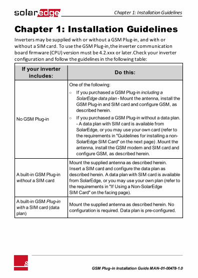
Chapter 1: Installation GuidelinesInverters may be supplied with or without a GSM Plug-in, and with or without a SIM card. To use the GSM Plug-in,the inverter communication board firmware (CPU) version must be 4.2.xxx or later.Check your inverter configuration and follow the guidelines in the following table:
If your inverter includes: Do this:
No GSM Plug-in
One of the following: o If you purchased a GSM Plug-in including a
SolarEdge data plan - Mount the antenna, install the GSM Plug-in and SIM card and configure GSM, as described herein.
o If you purchased a GSM Plug-in without a data plan.- A data plan with SIM card is available fromSolarEdge, or you may use your own card (refer to the requirements in "Guidelines for installing a non-SolarEdge SIM Card" on the next page) .Mount the antenna, install the GSM modem and SIM card and configure GSM, as described herein.
A built-in GSM Plug-in without a SIM card
Mount the supplied antenna as described herein.Insert a SIM card and configure the data plan as described herein. A data plan with SIM card is available from SolarEdge, or you may use your own plan (refer to the requirements in "If Using a Non-SolarEdge SIM Card" on the facing page).
A built-in GSM Plug-in with a SIM card (data plan)
Mount the supplied antenna as described herein. No configuration is required. Data plan is pre-configured.
Chapter 1: Installation Guidelines
GSM Plug-in Installation GuideMAN-01-00478-1.08
Chapter 1: Installation Guidelines
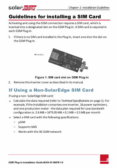
Guidelines for installing a SIM CardActivating and using the GSM connection requires a SIM card, which is inserted into a designated slot on the GSM Plug-in. A SIM card is required in each GSM Plug-in.
1. If there is no SIM card installed in the Plug-in, insert one into the slot on the GSM Plug-in.
Figure 1: SIM card slot on GSM Plug-in
2. Remove the inverter cover as described in its manual.
If Using a Non-SolarEdge SIM CardIf using a non- SolarEdge SIM card: l Calculate the data required (refer to Technical Specifications on page 1). For
example, if the installation comprises one inverter, 16 power optimizers, and one production meter - the data plan required for Low bandwith configuration is: 2.6 MB + 16*0.05 MB + 0.1 MB = 3.5 MB per month
l Select a SIM card with the following specifications: o μSIM o Supports SMS o Works with the 3G GSM network
GSM Plug-in Installation GuideMAN-01-00478-1.09
l Obtain the following details from your operator: o SIM phone number o PIN (Personal Identification Number) o MNO (Mobile Network Operator) o APN (Access Point Name) o User name
Chapter 1: Installation Guidelines
GSM Plug-in Installation GuideMAN-01-00478-1.010
Chapter 1: Installation Guidelines
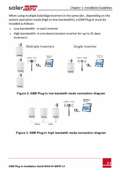
When using multiple SolarEdge inverters in the same site , depending on the system operation mode (high or low bandwidth), a GSM Plug-in must be installed as follows: l Low bandwidth - in each inverter l High bandwidth- in one device (master inverter for up to 31 slave
inverters )
Figure 2: GSM Plug-in low bandwith mode connection diagram
Figure 3: GSM Plug-in high bandwith mode connection diagram
GSM Plug-in Installation GuideMAN-01-00478-1.011
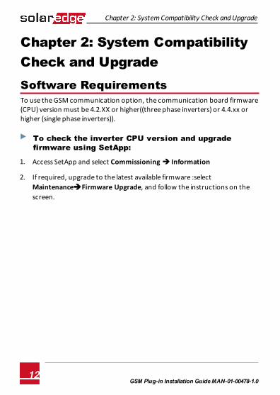
Chapter 2: System Compatibility Check and UpgradeSoftware RequirementsTo use the GSM communication option, the communication board firmware (CPU) version must be 4.2.XX or higher((three phase inverters) or 4.4.xx or higher (single phase inverters)).
To check the inverter CPU version and upgrade firmware using SetApp:
1. Access SetApp and select Commissioning è Information
2. If required, upgrade to the latest available firmware :select MaintenanceèFirmware Upgrade, and follow the instructions on the screen.
Chapter 2: System Compatibility Check and Upgrade
GSM Plug-in Installation GuideMAN-01-00478-1.012
Chapter 3: GSM Plug-in and Antenna Installation
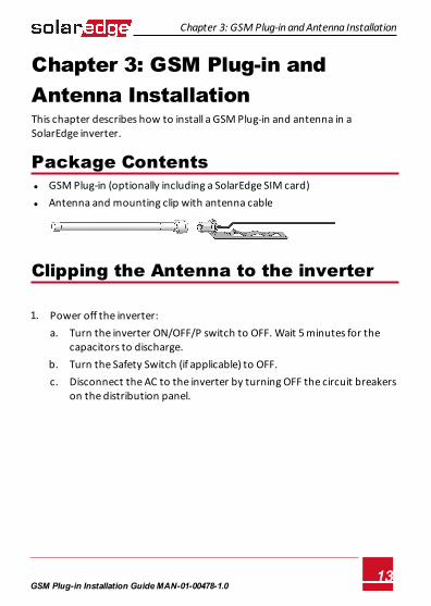
Chapter 3: GSM Plug-in and Antenna InstallationThis chapter describes how to install a GSM Plug-in and antenna in a SolarEdge inverter.
Package Contents l GSM Plug-in (optionally including a SolarEdge SIM card) l Antenna and mounting clip with antenna cable
Clipping the Antenna to the inverter
1. Power off the inverter: a. Turn the inverter ON/OFF/P switch to OFF. Wait 5 minutes for the
capacitors to discharge. b. Turn the Safety Switch (if applicable) to OFF. c. Disconnect the AC to the inverter by turning OFF the circuit breakers
on the distribution panel.
GSM Plug-in Installation GuideMAN-01-00478-1.013
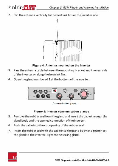
2. Clip the antenna vertically to the heatsink fins or the inverter side.
Figure 4: Antenna mounted on the inverter
3. Pass the antenna cable between the mounting bracket and the rear side of the inverter or along the heatsink fins.
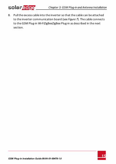
4. Open the gland numbered 1 at the bottom of the inverter.
Figure 5: Inverter communication glands
5. Remove the rubber seal from the gland and insert the cable through the gland body and the opened connection of the inverter.
6. Push the cable into the cut opening of the rubber seal.
7. Insert the rubber seal with the cable into the gland body and reconnect the gland to the inverter. Tighten the sealing gland.
Chapter 3: GSM Plug-in and Antenna Installation
GSM Plug-in Installation GuideMAN-01-00478-1.014
Chapter 3: GSM Plug-in and Antenna Installation
8. Pull the excess cable into the inverter so that the cable can be attachedto the inverter communication board (see Figure 7). The cable connects to the GSM Plug-in Wi-FiZigBeeZigBee Plug-in as described in the next section.
GSM Plug-in Installation GuideMAN-01-00478-1.015
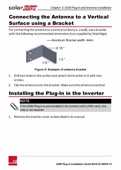
Connecting the Antenna to a Vertical Surface using a BracketFor connecting the antenna to a vertical surface (i.e. a wall), use a bracket with the following recommended dimensions (not supplied by SolarEdge):
Figure 6: Example of antenna bracket
1. Drill two holes in the surface and attach the bracket to it with twoscrews.
2. Clip the antenna onto the bracket. Make sure the antenna is vertical.
Installing the Plug-In in the InverterNOTE
If the GSM Plug-in is pre-installed in the inverter (with a SIM card), this step is not required.
1. Remove the inverter cover as described in its manual.
Chapter 3: GSM Plug-in and Antenna Installation
GSM Plug-in Installation GuideMAN-01-00478-1.016
Chapter 3: GSM Plug-in and Antenna Installation
To Install the Plug-in in the inverter:
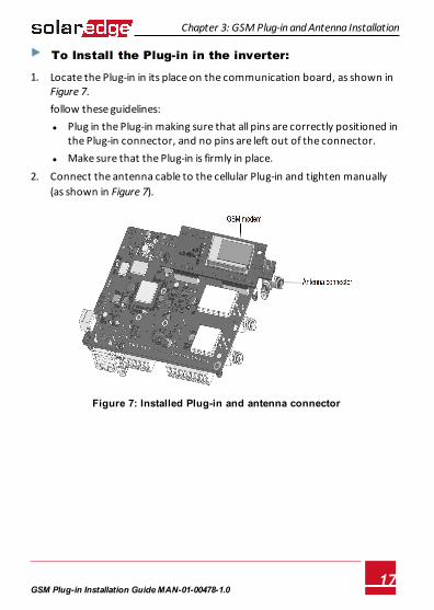
1. Locate the Plug-in in its place on the communication board, as shown in Figure 7.follow these guidelines: l Plug in the Plug-in making sure that all pins are correctly positioned in
the Plug-in connector, and no pins are left out of the connector. l Make sure that the Plug-in is firmly in place.
2. Connect the antenna cable to the cellular Plug-in and tighten manually (as shown in Figure 7).
Figure 7: Installed Plug-in and antenna connector
GSM Plug-in Installation GuideMAN-01-00478-1.017

3. Turn the AC ON.
WARNING!ELECTRICAL SHOCK HAZARD. Do not touch uninsulated wires when the cover is removed.
4. Check that all the GSM Plug-in LEDs are lit. If not, refer to "Viewing Error Messages and Troubleshooting" on page 25
Figure 8: GSM Plug-in LEDs
Chapter 3: GSM Plug-in and Antenna Installation
GSM Plug-in Installation GuideMAN-01-00478-1.018

Chapter 4: Configuring GSM Communication
Chapter 4: Configuring GSM Communication This chapter describes how to activate the GSM Plug-in if using a non-solarEdge SIM card, configure the inverter to use GSM communication, verify the connection and troubleshoot problems.
Configuring the Inverter 1. Ensure you have installed the Plug-in and antenna. For instructions see
"GSM Plug-in and Antenna Installation" on page 13.
2. Activate, commission and configure the installation (except for communication) according to the Inverter Installation Guide.
3. Access SetApp and select CommunicationèCellular 4. In the Cellular screen select Configurations
GSM Plug-in Installation GuideMAN-01-00478-1.019
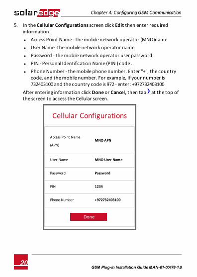
5. In the Cellular Configurations screen click Edit then enter required information. l Access Point Name - the mobile network operator (MNO)name l User Name -the mobile network operator name l Password - the mobile network operator user password l PIN - Personal Identification Name (PIN ) code . l Phone Number - the mobile phone number. Enter "+", the country
code, and the mobile number. For example, If your number is 732403100 and the country code is 972 - enter: +972732403100
After entering information click Done or Cancel, then tap› at the top of the screen to access the Cellular screen.
Cellular Configurations
Access Point Name
(APN)MNO APN
User Name MNO User Name
Password Password
PIN 1234
Phone Number +972732403100
Chapter 4: Configuring GSM Communication
GSM Plug-in Installation GuideMAN-01-00478-1.020
Chapter 4: Configuring GSM Communication
6. In the Cellular screen select Data Plan. Low bandwith is automtically selected as it is the default. l Low Bandwidth - This is the default mode that uses a data plan for
low-cost monitoring. In this mode, the data is sampled every 15 minutes and the server connection is established every 4 hours .In a multiple inverter system, a GSM Plug-in and a SIM card are required in every inverter. Configuring to Low BW is required in every inverter.
l High Bandwidth - This mode uses a data plan for high resolution monitoring. In this mode the Plug-in maintains a continuous connection with the server, and the data is sampled every 5 minutes. After optimizer pairing there is communication with the server for the first hour to simplify commissioning. In a multiple device system (up to 32), a GSM Plug-in and a SIM card are required in only one device. Configuring to High BW is required only in that device.
l To change to High Bandwith contact SolarEdge [email protected]
NOTEIf you want to change back to Low Bandwith, from the Data Plan options select Low Bandwith.
GSM Plug-in Installation GuideMAN-01-00478-1.021
7. Do one of the following :l If you leave Low Bandwith selected the following is displayed and
occurs:Auto Activation, the Plug-in connects to the server.If auto activation fails (the Unidentified # error message appears onthe status screen. For inforamtion see"Viewing Error Messages andTroubleshooting" on page 25 ) , select Manual Activation and in the screen that appears .Enter "+", the country code, and the mobile number. For example, If your number is 732403100 and the countrycode is 972 - enter: +972732403100
l If you select High BW, a message is displayed: Significant costmay be incurred. Proceed?. If you select Yes , the Plug-in attempts to establish communicationwith the monitoring server.
If Unidentified # error appears on the status screen (see instructions for accessing the Status screen in the next section) , refer to Viewing Error Messages and Troubleshooting on page 25
Chapter 4: Configuring GSM Communication
GSM Plug-in Installation GuideMAN-01-00478-1.022
Chapter 4: Configuring GSM Communication
Verifying the Connection and Viewing Communication Status You view error messages on the Status screen.
To access the SetApp Status screen:
1. Do one of the following: l During first time Commissioning and configuration: From the
Commissioning menu select Status. The main inverter Status screen is displayed (see on the following page)
l If the inverter has already been activated and commissioned - open SetApp and follow the instructions on the screen (scan the inverter bar-code; move the ON/OFF/P switch to P position (for less than 5 sec) and release).The mobile device creates a Wi-Fi connection with the inverter and displays the inverter main Status screen.
GSM Plug-in Installation GuideMAN-01-00478-1.023
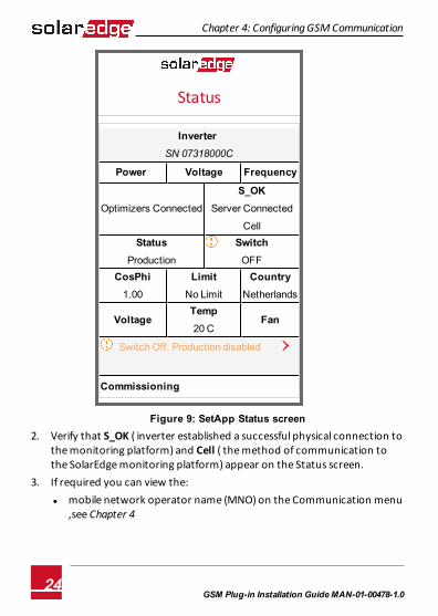
Status
Inverter SN 07318000C
Power Voltage Frequency
Optimizers Connected
S_OKServer Connected
CellStatus
Production
SwitchOFF
CosPhi1.00
LimitNo Limit
CountryNetherlands
VoltageTemp20 C
Fan
Switch Off. Production disabled ›
Commissioning
Figure 9: SetApp Status screen 2. Verify that S_OK ( inverter established a successful physical connection to
the monitoring platform) and Cell ( the method of communication to the SolarEdge monitoring platform) appear on the Status screen.
3. If required you can view the: l mobile network operator name (MNO) on the Communication menu
,see Chapter 4
Chapter 4: Configuring GSM Communication
GSM Plug-in Installation GuideMAN-01-00478-1.024
Chapter 4: Configuring GSM Communication
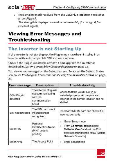
l The Signal strength received from the GSM Plug-in(Sig) on the Status screenFigure 9. The strength is displayed as a value between 0-5, (0 = no signal, 5 = excellent signal).
Viewing Error Messages and Troubleshooting
The Inverter is not Starting UpIf the inverter is not starting up, the Plug-in may have been installed in an inverter with an incompatible CPU software version.Check if the Plug-in is installed, remove it and upgrade the inverter as described in System Compatibility Check and Upgrade on page 12 . You view error messages on the SetApp screen. To access the SetApp Status screen see Verifying the Connection and Viewing Communication Status on page 23.
Error message Description Troubleshooting
GSM Plug-in detected
The internal Plug-in is not communicating with the communication board.
Check that the GSM Plug- in is installed properly: All the pins are inserted in the correct location and not shifted.
SIM not detected The SIM card is not inserted or not recognized.
Insert a valid SIM card and check it is inserted correctly.
Enter PIN
Personal Identification Name (PIN ) code is pending.
o Enter Setup mode o From Communication select
Cellular Conf,and set the PIN code according to the MNO (Mobile Network Operator).
Enter APN The Access Point o Enter Setup mode
GSM Plug-in Installation GuideMAN-01-00478-1.025
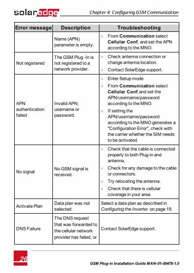
Error message Description Troubleshooting
Name (APN) parameter is empty.
o From Communication selectCellular Conf, and set the APN according to the MNO.
Not registeredThe GSM Plug -In is not registered to a network provider.
o Check antenna connection or change antenna location.
o Contact SolarEdge support.
APN authentication failed
Invalid APN, username or password.
o Enter Setup mode o From Communication select
Cellular Conf.and set the APN/username/password according to the MNO.
o If setting the APN/username/password according to the MNO generates a "Configuration Error", check with the carrier whether the SIM needs to be activated.
No signal No GSM signal isreceived.
o Check that the cable is connected properly to both Plug-in and antenna.
o Check for any damage to the cable or connectors.
o Try relocating the antenna. o Check that there is cellular
coverage in your area.
Activate Plan Data plan was notselected.
Select a data plan as described in Configuring the Inverter on page 19.
DNS Failure
The DNS request that was forwarded to the cellular network provider has failed, or
Contact SolarEdge support.
Chapter 4: Configuring GSM Communication
GSM Plug-in Installation GuideMAN-01-00478-1.026
Chapter 4: Configuring GSM Communication
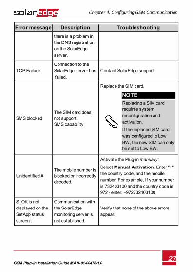
Error message Description Troubleshootingthere is a problem in the DNS registration on the SolarEdge server.
TCP FailureConnection to the SolarEdge server has failed.
Contact SolarEdge support.
SMS blockedThe SIM card does not support SMS capability
Replace the SIM card.
NOTEReplacing a SIM card requires system reconfiguration and activation.
If the replaced SIM card was configured to Low BW, the new SIM can only be set to Low BW.
Unidentified #The mobile number is blocked or incorrectly decoded.
Activate the Plug-in manually:
Select Manual Activation. Enter "+", the country code, and the mobile number. For example, If your number is 732403100 and the country code is 972 - enter: +972732403100
S_OK is not displayed on the SetApp status screen .
Communication with the SolarEdge monitoring server is not established.
Verify that none of the above errors appear.
GSM Plug-in Installation GuideMAN-01-00478-1.027
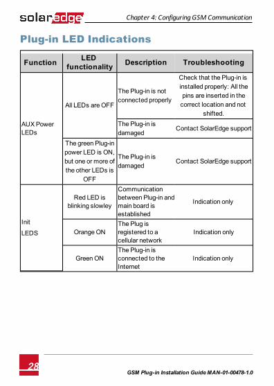
Plug-in LED Indications
Function LED functionality Description Troubleshooting
AUX Power LEDs
All LEDs are OFF
The Plug-in is not connected properly
Check that the Plug-in is installed properly: All the pins are inserted in the
correct location and not shifted.
The Plug-in is damaged
Contact SolarEdge support
The green Plug-in power LED is ON, but one or more of the other LEDs is
OFF
The Plug-in is damaged
Contact SolarEdge support
Init
LEDS
Red LED is blinking slowley
Communication between Plug-in and main board is established
Indication only
Orange ONThe Plug is registered to a cellular network
Indication only
Green ONThe Plug-in is connected to the Internet
Indication only
Chapter 4: Configuring GSM Communication
GSM Plug-in Installation GuideMAN-01-00478-1.028

Technical SpecificationsGSM Plug-in for US systems:
DATA PLAN (for Non-SolarEdgeSIM cards) High Bandwidth Low Bandwidth
Number of Inverters MonitoredWith aSingle GSM Kit Up to 32 1
Monitoring
Data sampledevery 5minutesand sent to
SolarEdge servercontinuously
Data sampledevery 15minutes
and sent toSolarEdge serverevery 4 hours
Monthly Data - per Inverter 7.8 2.6 MB
Monthly Data - per Optimizer 0.15 0.05 MB
Monthly Data - per RevenueGradeMeter 0.3 0.1 MB
Data per Export or ConsumptionMeter 3 0.55 MB
Monthly Data - per Battery 3 0.7 MB
RF Performance
Operating Frequency Min.-Max. 850Plug-in transmit: 824-849
MHzPlug-in receive: 869-894
Operating Frequency Min.-Max. 1900
Plug-in transmit:1850 -1910
MH Plug-inreceive:1930 -1990
AntennaIncluded, 2dBi outdoor; Dual bandantenna: 824-960MHz / 1710-2170
MHzMaximum output power 850MHzband 33 dBm
1
GSM Plug-In Technical Specifications MAN-01-00545-1.0
GSM Plug-In Technical Specifications MAN-01-00545-1.0
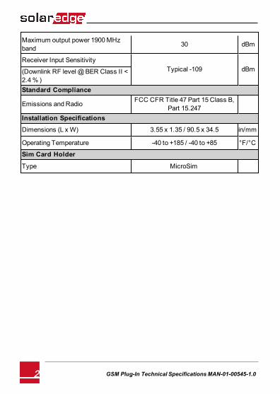
Maximum output power 1900MHzband 30 dBm
Receiver Input SensitivityTypical -109 dBm(Downlink RF level@BER Class II <
2.4% )Standard Compliance
Emissions and Radio FCC CFR Title 47 Part 15 Class B,Part 15.247
Installation Specifications
Dimensions (L x W) 3.55 x 1.35 / 90.5 x 34.5 in/mm
Operating Temperature -40 to +185 / -40 to +85 °F/°C
Sim Card Holder
Type MicroSim
2 GSM Plug-In Technical Specifications MAN-01-00545-1.0
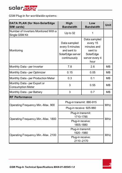
GSM Plug-in for worldwide systems:
DATA PLAN (for Non-SolarEdgeSIM cards)
HighBandwidth
LowBandwidth Unit
Number of Inverters MonitoredWith aSingle GSM Kit Up to 32 1
Monitoring
Data sampledevery 5minutesand sent to
SolarEdge servercontinuously
Data sampledevery 15
minutes andsent to
SolarEdgeserver every 4
hour
Monthly Data - per Inverter 7.8 2.6 MB
Monthly Data - per Optimizer 0.15 0.05 MB
Monthly Data - per ProductionMeter 0.3 0.1 MB
Monthly Data - per Export orConsumptionMeter 3 0.55 MB
Monthly Data - per Battery 3 0.7 MB
RF Performance
Operating Frequency Min.-Max. 900Plug-in transmit: 880-915
MHz Plug-in receive: 925-960
Operating Frequency Min.-Max. 1800
Plug-in transmit:1710-1785
MHz Plug-in receive:1805-1880
Operating Frequency Min.-Max. 2100
Plug-in transmit:1920 -1980
MHz Plug-in receive:2110 -2170
3GSM Plug-In Technical Specifications MAN-01-00545-1.0
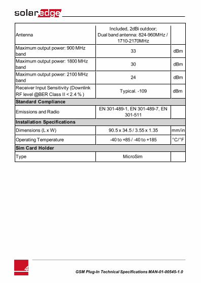
Antenna Included, 2dBi outdoor;
Dual band antenna: 824-960MHz /1710-2170MHz
Maximum output power: 900MHzband 33 dBm
Maximum output power: 1800MHzband 30 dBm
Maximum output power: 2100MHzband 24 dBm
Receiver Input Sensitivity (DownlinkRF level@BER Class II < 2.4% )
Typical. -109 dBm
Standard Compliance
Emissions and Radio EN 301-489-1, EN 301-489-7, EN301-511
Installation Specifications
Dimensions (L x W) 90.5 x 34.5 / 3.55 x 1.35 mm/in
Operating Temperature -40 to +85 / -40 to +185 °C/°F
Sim Card Holder
Type MicroSim
GSM Plug-In Technical Specifications MAN-01-00545-1.04