Embed Size (px)
Citation preview

© Dr. D H Pesch, CIT, 2000 1
GSM Interfaces and ProtocolsGSM Interfaces and Protocols
TelecommunicationsMSc in Software Development
© Dr. D H Pesch, CIT, 2000 2
IntroductionIntroduction
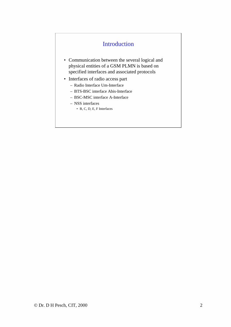
• Communication between the several logical and physical entities of a GSM PLMN is based on specified interfaces and associated protocols
• Interfaces of radio access part– Radio Interface Um-Interface
– BTS-BSC interface Abis-Interface
– BSC-MSC interface A-Interface
– NSS interfaces• B, C, D, E, F Interfaces

© Dr. D H Pesch, CIT, 2000 3
GSM InterfacesGSM Interfaces
MS
BTS
BSC MSCBTS
BTS
BTS
BTS
BTS
BSCUm
PSTN/ISDN
AAbis
MSC
Gateway
MSC
VLR
VLR
HLR
AUC
EIR
B
E
C
D
FSMS
Centre
OMC
Radio Subsystem
Base Station Subsystem(BSS)
Operation Subsystem (OSS)
Network & Switching Subsystem (NSS)
SIM

© Dr. D H Pesch, CIT, 2000 4
GSM ProtocolsGSM Protocols
Radio
LAP-Dm
64 kb/s G.703
LAP-D
MTP 1
MTP 2
MTP 3
SCCP
MTP 1
MTP 2
MTP 3
SCCP
MTP 1
MTP 2
MTP 3
SCCP
MTP 1
MTP 2
MTP 3
SCCP
MTP 1
MTP 2
MTP 3
RIL3 - RR
RIL3 - MM
RIL3 - CM
RSM BSSMAP MAP/E, MAP/G
Distribution Protocol TCAP
MAP/D MAP/C
TUP,ISUP
Application
Presentation
Session
Transport
Network
Data Link
Physical
OSI LayersMS BTS BSC
RelayMSC/VLR
AnchorMSC/VLR HLR/AuC
GMSCSMS Gateway
PSTN/ISDN
Um Abis A B, E, G C D

© Dr. D H Pesch, CIT, 2000 5
GSM Radio InterfaceGSM Radio Interface
• Combination of FDM and TDM
• Uplink and downlink have each 25MHz of total spectrum available
• Spectrum divided into 124 carrier frequencies
• Carrier spacing is 200kHz
• 8 time slots per carrier

© Dr. D H Pesch, CIT, 2000 6
MultiplexingMultiplexing
Frequency Slot 0 Slot 1 Slot 2 … Slot 7ch 1ch 2ch 3.....ch 124
Time1 Frame = 8 timeslotsFrame duration = 4.615 mstimeslot duration = 0.577 ms

© Dr. D H Pesch, CIT, 2000 7
TDMA Frame StructureTDMA Frame Structure
• Each TDMA frame divided into 8 time slots
• TDMA frames are grouped into two types of multiframes– 26-frame multiframe for traffic channels
– 51-frame multiframe for control channels
• Multiframes are multiplexed into single superframeof 6.12sec duration
• 2048 multiframes are combined into hyperframe

© Dr. D H Pesch, CIT, 2000 8

© Dr. D H Pesch, CIT, 2000 9
Channel TypesChannel Types
• Physical Channels– defined by carrier frequency/TDMA time slot combination
• Logical Channels– two types of logical channels
– Traffic Channels (TCH)
– Control Channels (CCH)

© Dr. D H Pesch, CIT, 2000 10
Traffic ChannelsTraffic Channels
• Traffic channels carry user information– speech
– data, FAX
• Two types of TCH– full rate channel with 22.8kbps gross bit rate
– half rate channel with 11.4kbps gross bit rate
• TCH are multiplexed into 26-frame multiframestructure

© Dr. D H Pesch, CIT, 2000 11
2626--frame frame MultiframeMultiframe
26-frame multiframe
T1 T2 T3 T4 T5 T10
T11
A T12
T21
T22
T23
I
Tn: time frame number n for traffic data.A: slow associated control channel.I: idle frame.

© Dr. D H Pesch, CIT, 2000 12
Control ChannelsControl Channels
• Control channels carry system control and synchronisation information
• Three categories are defined– Broadcast channel
– Common control channel
– Dedicated control channel
• Almost all control channels exist in the 51-frame multiframe structure

© Dr. D H Pesch, CIT, 2000 13
5151--frame frame MultiframeMultiframe
DOWNLINK (51 time frames)
F S B B B B C C F S C C C C C C F S C C C C C C C C I
F: frequency correction channelS: synchronisation channelB: broadcast control channelC: common control channel I: idle frame

© Dr. D H Pesch, CIT, 2000 14
Broadcast ChannelBroadcast Channel
• Frequency Correction Channel (FCCH)
• Synchronisation Channel (SCH)
• Broadcast Control Channel (BCCH)
© Dr. D H Pesch, CIT, 2000 15
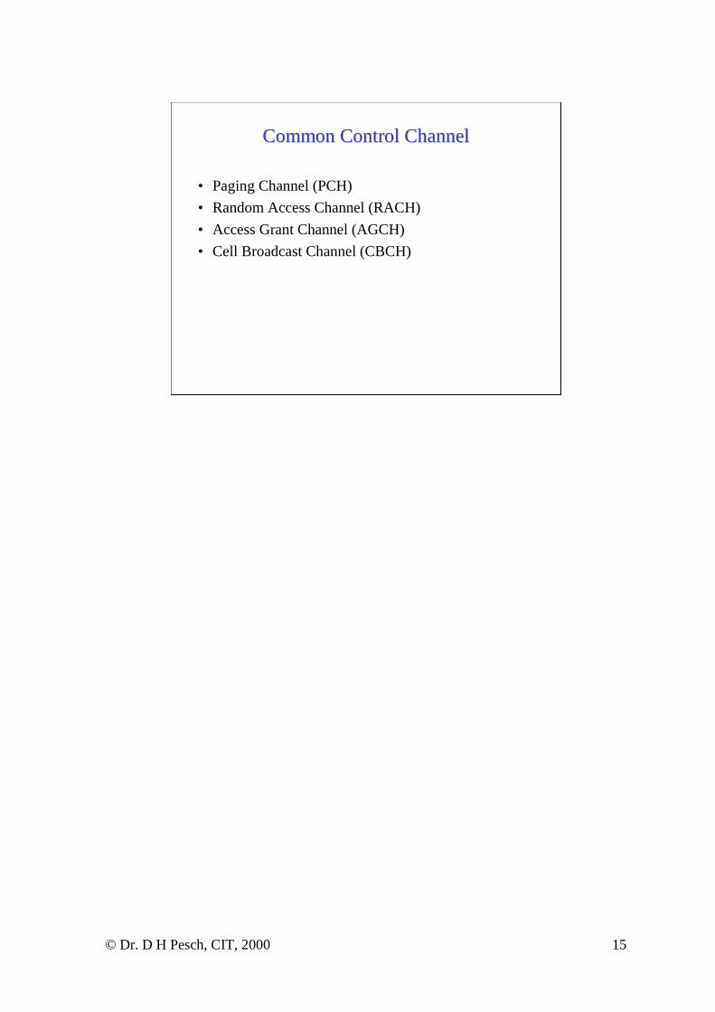
Common Control ChannelCommon Control Channel
• Paging Channel (PCH)
• Random Access Channel (RACH)
• Access Grant Channel (AGCH)
• Cell Broadcast Channel (CBCH)

© Dr. D H Pesch, CIT, 2000 16
Dedicated Control ChannelDedicated Control Channel
• Stand-alone Dedicated Control Channel (SDCCH)
• Slow Associated Control Channel (SACCH)
• Fast Associated Control Channel (FACCH)

© Dr. D H Pesch, CIT, 2000 17
Burst TypesBurst Types
• Normal Burst
• Frequency Correction Burst
• Synchronisation Burst
• Dummy Burst
• Access Burst

© Dr. D H Pesch, CIT, 2000 18
Burst TypesBurst Types
Start(3) Encrypted data (58) training (26) encrypted data (58) stop (3) Guard period (8.25)
Tail bits 57 bits data + 1 Stealing 57 bits data + 1 Stealing Tail bitsflag flag
Start(3) fixed bits (142) Stop (3) guard period (8.25)
start(3) encrypted data (39) Extended training (64) Encrypted data (39) stop (3) guard period (8.25)
extended start(8) synch. seq. (41) encrypted data (36) Stop (3) extended guard period (68.25)
Normal Burst
Frequency Correction Burst Burst
Synchronisation Burst
Access Burst
© Dr. D H Pesch, CIT, 2000 19
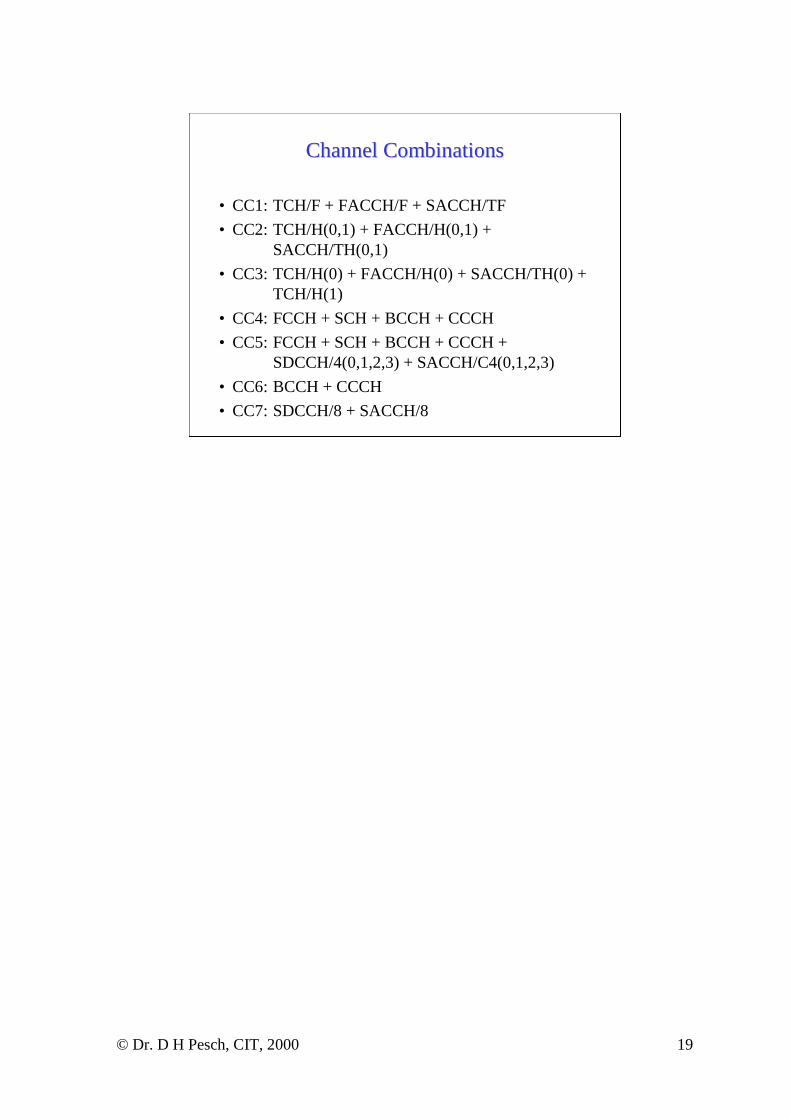
Channel CombinationsChannel Combinations
• CC1: TCH/F + FACCH/F + SACCH/TF
• CC2: TCH/H(0,1) + FACCH/H(0,1) + SACCH/TH(0,1)
• CC3: TCH/H(0) + FACCH/H(0) + SACCH/TH(0) + TCH/H(1)
• CC4: FCCH + SCH + BCCH + CCCH
• CC5: FCCH + SCH + BCCH + CCCH + SDCCH/4(0,1,2,3) + SACCH/C4(0,1,2,3)
• CC6: BCCH + CCCH
• CC7: SDCCH/8 + SACCH/8

© Dr. D H Pesch, CIT, 2000 20
Channel Combination 2Channel Combination 2
T0 T1 T0 T1 T0 T1 T0 T1 T0 T1 T0 T1 A0 T0 T1 T0 T1 T0 T1 T0 T1 T0 T1 T0 T1 A1
T0: TCH/H(0) A0: SACCH/TH(0)T1: TCH/H(1) A1: SACCH/TH(1) 26-frame multiframe

© Dr. D H Pesch, CIT, 2000 21
Channel Combination 5Channel Combination 5
F: FCCH D0: SDCCH/4(0) A0: SACCH/C4(0) R: RACHF: FCCH D1: SDCCH/4(1) A1: SACCH/C4(1)F: FCCH D2: SDCCH/4(2) A2: SACCH/C4(2)F: FCCH D3: SDCCH/4(3) A3: SACCH/C4(3) 2 x 51-frame multiframe
F S B B B B C C C C F S C C C C C C C C F S D0 D0 D0 D0
D1 D1 D1 D1 F S D2 D2 D2 D2 D3 D3 D3 D3 F S A0 A0 A0 A0 A1 A1 A1 A1 -
F S B B B B C C C C F S C C C C C C C C F S D0 D0 D0 D0
D1 D1 D1 D1 F S D2 D2 D2 D2 D3 D3 D3 D3 F S A2 A2 A2 A2 A3 A3 A3 A3 -
D3 D3 D3 D3 R R A2 A2 A2 A2 A3 A3 A3 A3 R R R R R R R R R R R R
R R R R R R R R R R R D0 D0 D0 D0 D1 D1 D1 D1 R R D2 D2 D2 D2
Uplink
Downlink
D3 D3 D3 D3 R R A0 A0 A0 A0 A1 A1 A1 A1 R R R R R R R R R R R R
R R R R R R R R R R R D0 D0 D0 D0 D1 D1 D1 D1 R R D2 D2 D2 D2

© Dr. D H Pesch, CIT, 2000 22
CC based on Cell LoadCC based on Cell Load
� Low capacity cell with one TRX
- TN 0: FCCH + SCH + BCCH + CCCH + SDCCH/4(0,1,2,3) + SACCH/C4(0,1,2,3)- TN1 to TN7: TCH/F + FACCH/F + SACCH/TF
� Medium capacity cell with four TRX
- Once (on TN 0): FCCH + SCH + BCCH + CCCH- Twice (on TN2 and TN4): SDCCH/8 + SACCH/8- 29 times: TCH/F + FACCH/F + SACCH/TF
� High capacity cell with 12 TRXs
- Once on TN0: FCCH + SCH + BCCH + CCCH- Once on TN2: BCCH + CCCH- Once on TN4: BCCH + CCCH- Once on TN6: BCCH + CCCH- 5 times: SDCCH/8 + SACCH/8- 87 times: TCH/F + FACCH/F + SACCH/TF
1. Notice that a BCCH always appears in TN 0 together with the logical channelsSCH and FCCH.
2. Additional combinations CC6 are added when traffic is expected to be heavy.

© Dr. D H Pesch, CIT, 2000 23
Channel CodingChannel Coding
• Block Code– Fire Code adds 40 bits redundancy, used on control
channels
– Generator polynomial P(X) = (X23 + 1)(X17 + X3 + 1)
• Convolutional Code– coder rates of 1/2, 1/3, 1/6, and 244/456
• Interleaving

© Dr. D H Pesch, CIT, 2000 24
InterleavingInterleaving
08
M
440448
19
M
441449
210
M
442450
311
M
443451
412
M
444452
513
M
445453
614
M
446454
715
M
447455
0 8 … 440 448
1 9 … 441 449
2 10 … 442 450
3 11 … 443 451
4 12 … 444 452
5 13 … 445 453
6 14 … 446 454
7 15 … 447 455
Burst N (even bit)
Burst N+1 (even bit)
Burst N+2 (even bit)
Burst N+3 (even bit)
Burst N+4 (odd bit)
Burst N+5 (odd bit)
Burst N+6 (odd bit)
Burst N+7 (odd bit)

© Dr. D H Pesch, CIT, 2000 25
InterleavingInterleaving

© Dr. D H Pesch, CIT, 2000 26
Coding on Logical ChannelsCoding on Logical Channels
Channel Type Bit/BlockData+Parity+Tail
ConvolutionalCoding Rate
Bit/Block
Interleavingdepth
TCH/FS 456 8Class I 182 + 3 + 4 1/2 (378)Class II 78 + 0 + 0 - (78)
TCH/F9.6 4 * 60 + 0 + 4 244/456 456 19TCH/F4.8 60 + 0 + 16 1/3 228 19TCH/H4.8 4 * 60 + 0 + 4 244/456 456 19TCH/F2.4 72 + 0 + 4 1/6 456 8TCH/H2.4 72 + 0 + 4 1/3 228 19FACCHs 184 + 40 + 4 1/2 456 8SDCCHs, SACCHs 184 + 40 + 4 1/2 456 4BCCH, AGCH, PCH 184 + 40 + 4 1/2 456 4RACH 8 + 6 + 4 1/2 36 1SCH 25 + 10 + 4 1/2 78 1

© Dr. D H Pesch, CIT, 2000 27
ModulationModulation
• GMSK
• BT = 0.3

© Dr. D H Pesch, CIT, 2000 28
Timing AdvanceTiming Advance
TS 0 TS 1 TS 2 TS 3 TS 4 TS 5
TS 5 TS 6 TS 7TA
TS 1 TS 2
3 TSs
The actual point in time of the transmission is shifted by theTiming Advance.
Receivi
Sending

© Dr. D H Pesch, CIT, 2000 29
Signalling Application ProtocolsSignalling Application Protocols
• Radio Interface Layer (RIL) Protocols– Radio Resource (RR) Management
– Mobility Management (MM)
– Call Management (CM)
• BSS and NSS Protocols– Common Channel Signalling System #7 (CCS7)
– TCAP
– GSM MAP

© Dr. D H Pesch, CIT, 2000 30
AAbisbis--InterfaceInterface
• Interface between BTS and BSC
• Non-standardised interface, manufacturers follow certain guidelines
• Based on transmission of data on a PCM 30 interface (2.048Mb/s transmission rate partitioned into 32 channels of 64 kb/s each)
• Voice compression can pack between 4 and 8 voice channels into single PCM 30 channel.

© Dr. D H Pesch, CIT, 2000 31
BSS ConfigurationsBSS Configurations
• Networking between BTSs and BSCs
• Multiplexing of user data
• Typical network configurations– Star Configuration
– Ring Configuration
– Serial Configuration

© Dr. D H Pesch, CIT, 2000 32
Star ConfigurationStar Configuration

© Dr. D H Pesch, CIT, 2000 33
Serial ConfigurationSerial Configuration

© Dr. D H Pesch, CIT, 2000 34
Ring ConfigurationRing Configuration

© Dr. D H Pesch, CIT, 2000 35
Multiplexing Multiplexing -- Star ConfigurationStar Configuration
FAS/NFAS
Air 0 Air 1 Air 2 Air 3
Air 4 Air 5 Air 6 Air 7
Air 0 Air 1 Air 2 Air 3
Air 4 Air 5 Air 6 Air 7
Air 0 Air 1 Air 2 Air 3
Air 4 Air 5 Air 6 Air 7
Air 0 Air 1 Air 2 Air 3
Air 4 Air 5 Air 6 Air 7
Air 0 Air 1 Air 2 Air 3
Air 4 Air 5 Air 6 Air 7
Air 0 Air 1 Air 2 Air 3
Air 4 Air 5 Air 6 Air 7
Air 0 Air 1 Air 2 Air 3
Air 4 Air 5 Air 6 Air 7
Air 0 Air 1 Air 2 Air 3
Air 4 Air 5 Air 6 Air 7
0
1
2
3
4
5
6
7
8
9
10
11
12
13
14
15
16
Not used
Not used
Partial O&M data
Not used
O&M signalling
TRX 8 signalling
TRX 2 signalling
TRX 6 signalling
TRX 5 signalling
TRX 4 signalling
TRX 3 signalling
TRX 7 signalling
TRX 1 signalling
Not used
Not used
17
18
19
20
21
22
23
24
25
26
27
28
29
30
31
TRX 1
TRX 5
TRX 2
TRX 6
TRX 3
TRX 7
TRX 4
TRX 8

© Dr. D H Pesch, CIT, 2000 36
Multiplexing Multiplexing -- Serial ConfigurationSerial ConfigurationFAS/NFAS
Air 0 Air 1 Air 2 Air 3
Air 4 Air 5 Air 6 Air 7
Air 0 Air 1 Air 2 Air 3
Air 4 Air 5 Air 6 Air 7
Air 0 Air 1 Air 2 Air 3
Air 4 Air 5 Air 6 Air 7
Air 0 Air 1 Air 2 Air 3
Air 4 Air 5 Air 6 Air 7
Air 0 Air 1 Air 2 Air 3
Air 4 Air 5 Air 6 Air 7
Air 0 Air 1 Air 2 Air 3
Air 4 Air 5 Air 6 Air 7
Air 0 Air 1 Air 2 Air 3
Air 4 Air 5 Air 6 Air 7
Air 0 Air 1 Air 2 Air 3
Air 4 Air 5 Air 6 Air 7
0
1
2
3
4
5
6
7
8
9
10
11
12
13
14
15
16
Not used
Partial O&M data
BTS4/TRX1 signalling
BTS3/TRX2 signalling
BTS3/TRX1 signalling
BTS2/O&M signalling
BTS2/TRX1 signalling
BTS1/TRX2 signalling
BTS4 O&M signalling
BTS3 O&M signalling
BTS2/TRX2 signalling
BTS1/O&M signalling
BTS1/TRX1 signalling
Transmission Control Information
17
18
19
20
21
22
23
24
25
26
27
28
29
30
31
BTS1/TRX1
BTS3/TRX1
BTS1/TRX2
BTS3/TRX2
BTS2/TRX1
BTS4/TRX1
BTS2/TRX2
BTS4/TRX2
BTS4/TRX2 signalling

© Dr. D H Pesch, CIT, 2000 37
Control Signalling on the Control Signalling on the AAbisbis--InterfaceInterface
• Layer 1 uses 64kb/s D-channel on E1 line (G.701/702) protocol
• Layer 2 uses the ISDN LAPD protocol
• Layer 3 divided into four parts– TRX Management (TRXM)
– Common Channel Management (CCM)
– Radio Link Management (RLM)
– Dedicated Channel Management (DCM)

© Dr. D H Pesch, CIT, 2000 38
AAbisbis--Interface Protocol StackInterface Protocol Stack
D-Channel
LAPD
TRXM
User data (CC, RR, MM)
Layer 1
Higher Layers
CCM RLM DCM
Layer 2
Layer 3

© Dr. D H Pesch, CIT, 2000 39
Layer 2 Layer 2 -- LAPDLAPD
• GSM adopted basically ISDN layer 2 LAPD as defined in ITU recommendations Q.920 and Q.921
• Uses three frame types based on more general HDLC– Information frame group containing the I-frame
– Supervisory frame group containing the RR, RNR, REJ frames
– Unnumbered frame group containing the SABME, DM, UI, DISC, UA, FRMR, and XID frames
• Two protocol options based on window length of 8 and 128– GSM uses mainly the 128 window length option

© Dr. D H Pesch, CIT, 2000 40
LAPD Frame FormatLAPD Frame Format

© Dr. D H Pesch, CIT, 2000 41
Layer 2 AddressingLayer 2 Addressing
• LAPD uses three SAPI (0, 62, and 63) to layer 3– SAPI 0 - radio signalling (radio signalling link, RSL)
• connection setup, release
• SMS and supplementary services messages
– SAPI 62 - O&M messages (O&M link, OML)
– SAPI 63 - Layer 2 management
– SAPI 62 and 63 messages have priority so that during congestion the network can still be managed

© Dr. D H Pesch, CIT, 2000 42
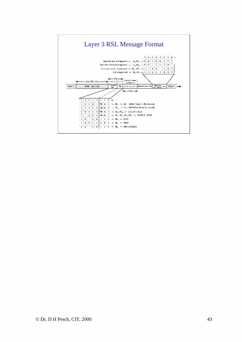
Layer 3 SignallingLayer 3 Signalling
• Layer 3 consists of four parts– TRXM, CCM, DCM, RLM
• message transmission and format depends on SAPI– SAPI = 0 for radio link signalling, carries user data from
CC, MM, RR, and also SMS and SS
– SAPI = 62, 63 for OMC and layer 2 management.
© Dr. D H Pesch, CIT, 2000 43
Layer 3 RSL Message FormatLayer 3 RSL Message Format

© Dr. D H Pesch, CIT, 2000 44
Example Messages for RLMExample Messages for RLM
ID (Hex) Name Direction Description01 DATA REQuest BSC → BTS Transport container for transparent transfer of
BSSAP data from NSS to MS02 DATA INDication BTS → BSC Transport container for transparent transfer of BSSAP
data from MS to NSS04 ESTablish REQuest BSC → BTS Request for BTS to establish layer 2 connection on
radio interface.05 ESTablish CONFirm BTS → BSC Answer to EST_REQ. Message sent to BSC after
BTS receives an LAPDm UA frame from MS06 ESTablish INDication BTS → BSC Response from BTS on receiving an LAPDm SABM
frame from MS07 RELease REQuest BSC → BTS Request to BTS to release current layer 2 connection.
BTS sends an LAPDm DISC frame to MS.0A UNIT DATA REQuest BSC → BTS Transport frame to send messages sent in LAPDm UI
frames over radio interface0B UNIT DATA
INDicationBTS → BSC Transport frame for messages received in LAPDm UI
frames over radio interface

© Dr. D H Pesch, CIT, 2000 45
Example Messages for CCM and TRXMExample Messages for CCM and TRXM
ID (Hex) Name Direction Description11 BCCH INFOrmation BSC → BTS Transport frame for SYS_INFO messages for
transmission in BCCH on time slot 012 CCCH LOAD
INDicationBTS → BSC Informs BSC about traffic load on CCCH of radio
interface. Frequency of transmission may be adjustedby OMC.
13 CHANnel ReQuireD BTS → BSC Message sent by BTS on receipt of CHAN_REQ byMS.
15 PAGing CoMmanD BSC → BTS Response of the BSC on receipt of a PAGINGcommand from MSC. Contains IMSI and/or TMSIand the paging group of called MS
16 IMMediate ASSignCoMmanD
BSC → BTS Contains all information for assignment of a SDCCHon radio interface. Transmitted in response toreceiving a correct CHAN_RQD.
19 RF RESourceINDication
BTS → BSC BTS uses this message to periodically inform BSCabout quality and quantity of available resources onradio interface. Allows BSC to refrain from assigningchannels with poor quality.
1C ERROR REPORT BTS → BSC Used when error is detected by TRX and no otherresponse message exists.

© Dr. D H Pesch, CIT, 2000 46
Example Messages for DCMExample Messages for DCMID (Hex) Name Direction Description21 CHANnel ACTivation BSC → BTS Message to reserve and activate channels on the radio
interface. Contains accurate description of requestedchannel (half/full rate, DTX on/off, channel type,etc.)
22 CHANnel ACTivationACKnowledge
BTS → BSC BTS acknowledges with this message reception ofCHAN_ACT message and activation of requestedchannel.
24 CONNection FAILure BTS → BSC Message is sent in case of layer 1 problems on theradio interface
25 DEACTivate SACCH BSC → BTS Requests BTS to stop transmission over the SACCH.The DEACT_SACCH is part of the release procedure
26 ENCRyptionCoMmanD
BSC → BTS Activation of ciphering on the radio interface.Message contains the algorithm A5/X to be used.
27 HANDover DETect BTS → BSC HND_DET is used during handover (not for intra-BTS and intra-BSC handover). After target cell hasreceived the HND_ACC message it calculates thedistance to MS (TA) and sends result in HND_DETmessage to BSC. It also informs MSC aboutsuccessful handover as soon as possible to allow forfaster switching of the call.
28 MEASurement RESult BTS → BSC Contains the mutual measurement result of the MSand BTS.
2E RF CHANnel RELease BSC → BTS RF_CHAN_REL message is sent to BTS after releaseof layer 2 connection to request release of layer 1connection.
2F MS POWERCONTROL
BSC → BTS Message used by BSC to adjust the MS transmitterpower according to current radio conditions
30 BS POWERCONTROL
BSC → BTS Message used by BSC to adjust the BTS transmitterpower according to current radio conditions

© Dr. D H Pesch, CIT, 2000 47
Layer 3 O&M Signalling Layer 3 O&M Signalling
• Messages depend on individual equipment manufacturer
• Management messages as well as software updates and file transfer are included in signalling
• Message transfer distinguishes between O&M messages and HMI/MMI messages

© Dr. D H Pesch, CIT, 2000 48
Layer 3 OML Message FormatLayer 3 OML Message Format

© Dr. D H Pesch, CIT, 2000 49
The GSM AThe GSM A--InterfaceInterface
• Interface between BSS and MSC
• Standardised interface allows mixing of equipment from different manufacturers
• A-Interface at physical level consists of two parts– First part between BSS and TRAU, transmission payload
is still compressed
– Second part between TRAU and MSC
• A-Interface at higher layers depens on SS7 MTP and SCCP to carry BSSAP

© Dr. D H Pesch, CIT, 2000 50
Multiplexing on AMultiplexing on A--InterfaceInterface

© Dr. D H Pesch, CIT, 2000 51
AA--Interface Protocol StackInterface Protocol Stack
MTP1-3
SCCP
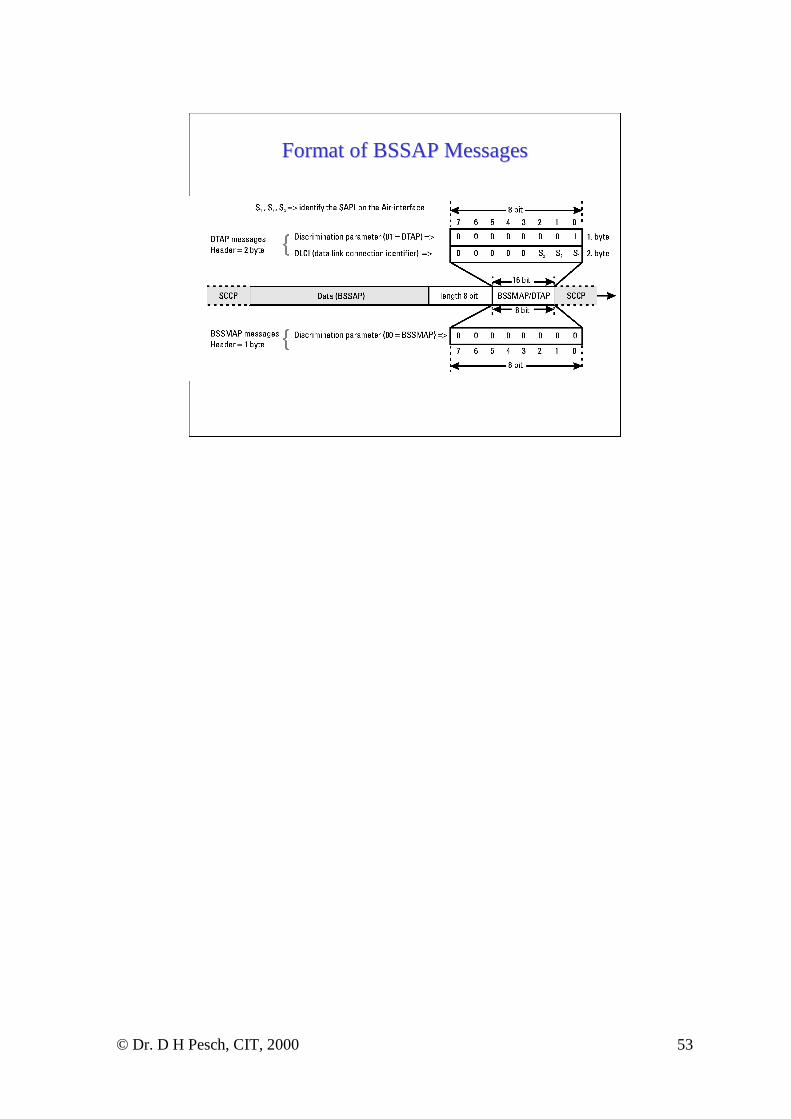
BSSMAP
DTAP
Layer 1 -3
User data BSSAP

© Dr. D H Pesch, CIT, 2000 52
AA--Interface Message RelationshipsInterface Message Relationships
MOBILE
STATION
BSS
MSC
RadioResource
Management(RR) BSSMAP
Call Control (CC)
Mobility Mgt. (MM)
DTAP
© Dr. D H Pesch, CIT, 2000 53
Format of BSSAP MessagesFormat of BSSAP Messages

© Dr. D H Pesch, CIT, 2000 54
Example BSSMAP MessagesExample BSSMAP MessagesID (Hex) Name Direction Description01 ASSignment REQuest MSC → BSC Sent from MSC to setup channel on radio interface
and A-interface. BSC selects TCH out of list ofavailable channels and assigns channel by means ofASS_CMD.
10 HaNDover REQuest MSC → BSC If the BSC needs to be changed during handover, thismessage is sent by the MSC to the new BSC.
11 HaNDover ReQuireD BSC → MSC BSC uses message to request handover from MSC(only intra-MSC and inter-MSC).
1B HaNDover DETect BSC → MSC BSC reacts with this message when it receives aHND_DET message from the BTS on the Abis-interface.
20 CleaR CoMmanD MSC → BSC This message is always used to release the radioresources to a specific MS.
30 RESET BSC ↔ MSC In case of fatal errors with serious data incon-sistencies between MSC and BSC reset is performed.RESET message is used to synchronise BSC andMSC again. The message is also used when the A-interface is originally initialised
32 OVERLOAD BSC ↔ MSC Send to MSC in order to indicate overlaod situationin BTS or whole BSS. Possible to specify type ofoverload. MSC sends message to indicate processoroverload in the switch.
34 RESet CIRCuit BSC ↔ MSC RES_CIRC is used like RESET. However,RES_CIRC only resets individual time slots on theA-interface rather than whole trunks.
40 BLOCK BSC → MSC Individual traffic channels need sometimes to beblocked for traffic.
50 RESource REQuest MSC → BSC MSC requests BSC with this message to provideupdated information on the available radio resourcesof a BTS.
52 PAGING MSC → BSC In case of a mobile terminating call the MSC sends aPAGING message to all BSC of a location area.
53 CIPHER MODECoMmanD
MSC → BSC This message is sent in order to start ciphering on theradio interface.

© Dr. D H Pesch, CIT, 2000 55
GSM Mobile Application PartGSM Mobile Application Part
• GSM uses the Mobile Application Part (MAP), a special application layer signalling protocol at all interfaces in the NSS
• MAP uses the SS7 protocol stack for message transmission between entities in the NSS
• MAP sits on top of SS7 TCAP and uses services of TCAP’sstructured dialogue for message transmission
• In typical applications MAP is often integrated with TCAP
• Dialogue between MAP applications starts with BEGIN and ends with END message

© Dr. D H Pesch, CIT, 2000 56
GSM MAP
MAP and TCAP within SS7MAP and TCAP within SS7
TCAP
SCCP
HLR VLR MSC EIR
Layer 4 - 6
Layer 7
Layer 3
Application Users

© Dr. D H Pesch, CIT, 2000 57
TCAPTCAP
• GSM TCAP uses exclusively the connectionless service of SCCP (protocol classes 0 and 1)
• Sending TCAP directly addresses the destination via the SCCP usually using the destinations global title (GT) address
• In GSM the global title is typically an entities ISDN number

© Dr. D H Pesch, CIT, 2000 58
Generic communication via TCAPGeneric communication via TCAP

© Dr. D H Pesch, CIT, 2000 59
MAP and its relationship with MAP and its relationship with TCAP’sTCAP’ssublayerssublayers

© Dr. D H Pesch, CIT, 2000 60
Coding of Data in TCAPCoding of Data in TCAP
• TCAP can encode length indicators from one byte to several thousand bytes
• Several parameter types are supported and encoding uses ASN.1 and associated encoding rules
• GSM uses the standard TCAP data encoding structure of three component elements (TLV convention)– Identifier (Type) T
– Length of Value L
– Contents (Value) V

© Dr. D H Pesch, CIT, 2000 61
Example Coding of an IMSI in TCAPExample Coding of an IMSI in TCAP

© Dr. D H Pesch, CIT, 2000 62
TCAP messages used in GSMTCAP messages used in GSM• Of the five defined TCAP messages, GSM uses only four
– BEGin• Opens dialog for one user (MAP) to another user; comprises
originating transaction ID.
– END• Specifically ends a dialog process, which was started by BEG;
may contain an optional component part with MAP data
– CONtinue• Used between BEG and END to transport data; comprises of both
originating and destination transaction ID; first CON after BEG confirms that protocol and context are ok.
– ABorT• Both TCAP and MAP may use ABT to abort process if error or
processing difficulty; reason may be provided; distinction is made between user and provider (U-ABORT and P-ABORT)

© Dr. D H Pesch, CIT, 2000 63
Structure of TCAP messagesStructure of TCAP messages

© Dr. D H Pesch, CIT, 2000 64
Structure of TCAP messagesStructure of TCAP messages

© Dr. D H Pesch, CIT, 2000 65
Structured Dialog in MSCStructured Dialog in MSC--toto--MSC MSC TransactionTransaction
© Dr. D H Pesch, CIT, 2000 66
Component PortionComponent Portion
• The component portion is optional, but if present, contains user data– INVOKE Component
– RETURN RESULT Component
– RETURN ERROR Component
– REJECT Component

© Dr. D H Pesch, CIT, 2000 67
Example use of Example use of return resultreturn result ComponentComponent

© Dr. D H Pesch, CIT, 2000 68
Decoding of an END MessageDecoding of an END Message

© Dr. D H Pesch, CIT, 2000 69
Decoded END MessageDecoded END Message

© Dr. D H Pesch, CIT, 2000 70
MAP ServicesMAP Services
• MAP used to control communication between signalling application users such as HLR, VLR, and MSC
• MAP offers the following services– MAP-DELIMITER service
– MAP-OPEN service
– MAP-CLOSE service
– MAP-U-ABORT service
– MAP-P-ABORT service
– MAP-NOTICE service

© Dr. D H Pesch, CIT, 2000 71
Special MAP ServicesSpecial MAP Services
• Special MAP services (local operation codes in GSM terminology) define the actual type of data exchange between MAP users
• Examples– updateLocation
– cancelLocation
– registerSS
– eraseSS
– sendRoutingInfo
– prepareHandover

© Dr. D H Pesch, CIT, 2000 72
Direction of MAP ServicesDirection of MAP Services

© Dr. D H Pesch, CIT, 2000 73
Interaction between MAP and TCAPInteraction between MAP and TCAP